PART VI. PRACTICAL RECIPES. (continued 2)
Reading edition
On the contrary, theory and practice are in perfect accord: the apparent disagreement arises from an error in the application of the geometrical laws.
In copying the theoretical forms of the teeth of wheels and leaves of pinions, it would be necessary to ascertain that they were mathematically exact, and this is impracticable. Two conditions must be borne in mind:
1. Theory shows that the mobile which drives should be made a trifle larger than the geometrical size, so as to counteract imperfections in the workmanship.
2. A pinion is never made of the exact mathematical proportions, in consequence of the processes that have to be adopted for cutting, polishing, centering, etc. If a number of pinions be taken, and if the several dimensions of each be determined by means of a micrometer measuring to hundredths of a millimeter (or from two to three-thousandths of an inch), differences that are, comparatively speaking, large will be found in the diameters, measuring between corresponding leaves; in the thickness of leaves; in the diameters of the circles at which the roundings join the straight faces, and the general truth of the pinion will nearly always leave something to be desired. It should be added that these faults will be more marked according as the leaves have been more quickly made.
The teeth of wheels will be found to be characterized by similar faults, although they are less marked.
571. It follows from these facts that, in watches and timepieces, the pinion is always a little smaller than theory would require; thus the epicycloid should be struck with a somewhat smaller generating circle, and the ogive of the tooth will be proportionately reduced.
The practical conclusion at which we arrive, then, is as follows: As it is impossible to secure absolute perfection in the teeth of small horological mechanisms, their ogives must be slightly more rounded at the points than the designs given in scientific treatises indicate, since these latter are drawn exactly in accordance with the geometrical laws.
These remarks are of the greatest possible importance to the manufacturers of both watches and timepieces; they point to the fact that not only the ogives of all wheel teeth should be lower than theory indicates, but also that, in commoner work, they must be still lower, according as the pinions are of more inferior quality.
572. To Alter a Stem Winding Pinion Depth. The depth of the Stem Winding Wheel and Pinion often occasions considerable inconvenience, and its adjustment requires to be accurately made: when the depth is too deep, its alteration is easy, as the roundings of the pinion leaves can be reduced, or the stud or other piece that carries the winding wheel can have its base a little reduced on one side, so as to set the wheel a trifle out of upright (but so slightly as not to be perceptible to the eye, and taking care that the teeth remain on a level with those of the barrel-arbor wheel). A shallow depth is somewhat more difficult to correct. If a sufficient change cannot be made by altering the support of the winding wheel, one of the following methods must be resorted to:
1. Reset the pendant of the case.
2. Make a new winding pinion of greater diameter, increasing the number of its leaves by one, to correspond to this change.
3. Alter the position of the movement in the case.
The two first methods are more especially applicable to new work, while the third is more convenient for repairers, although of course it can only be resorted to with advantage when the pinion has a bearing in the pendant. The requisite change in the position of the movement can be produced by raising the rim of the case that supports the plate, or by soldering two thin strips of metal on this rim, producing a similar effect; one on either side of the pendant will suffice, except when a considerable change is necessary, in which case they should be set at intervals around the rim to avoid an obvious inclination of the dial. Or four holes can be drilled at equal distances apart around the edge of the plate and in its plane, so that their edges overlap the position occupied by the rim of the case; pins are then set in these holes and filed away until they produce the requisite amount of elevation. Or, again, flat-headed screws may be fitted around the edge with their axes at right angles to the plane of the plate and their heads on the dial side.[7] The depth will then be adjusted by screwing these screws more or less into the plate.
It is advisable to ascertain that the dial is not forced too near the glass, as such is occasionally found to be the case, necessitating the bevelling of the edge of the former.
PALLETS.
573. To Advance a (visible) Jewel in a Pallet. Workmen that have had much experience of escapement making do this without any difficulty by holding the pallet arm in a pair of tweezers that have been slightly warmed, but ordinary repairers will not succeed with such a method: they can however, effect the required change as follows.
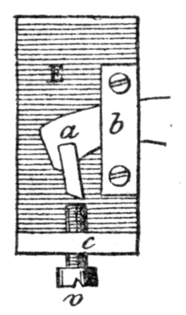
Fig.
257
.
Make a small brass plate, E, fig. 257, with a piece c projecting upwards, which the screw v traverses with stiff friction. A saddle b is fitted to the edge of the plate by screws. A glance at the figure will suffice to show the mode of using it; the pallet arm whose jewel is to be adjusted is clamped under b with the jewel just opposite the screw v. Now turn this screw until it stands at the distance from the impulse face of a through which the jewel is to be advanced; taking the plate in a pair of long-nosed pliers, hold them over a small lamp flame, and press with a small screwdriver lightly against the point a so as to advance the stone by the requisite amount as soon as the shellac is sufficiently soft. A particle of shellac is placed at a, if any cavity forms during the process, and the plate is laid on some cool body, avoiding contact with the pallet-staff.
If the stone projects below the lower surface of the pallets, a small washer must be placed underneath before clamping the screws of b, of such a thickness that the stone is just on the level with the surface E.
574. To Alter the Form of a Pallet Face. Workmen that possess the requisite skill and steadiness of hand can alter the form of a pallet jewel, when it is necessary to modify the height or form of the impulse face, by simply using a copper polisher charged with diamond powder. The polishing material employed is always decanted in very pure oil, as otherwise it is apt to scratch instead of polish. The coarser quality is first used when a material change has to be effected, but if only a very slight alteration is necessary, and the adjustment has to be very exact, only the finest quality must be used, as there is a danger of making scratches that would be very difficult to erase. We would also add that this operation requires some skill and patience.
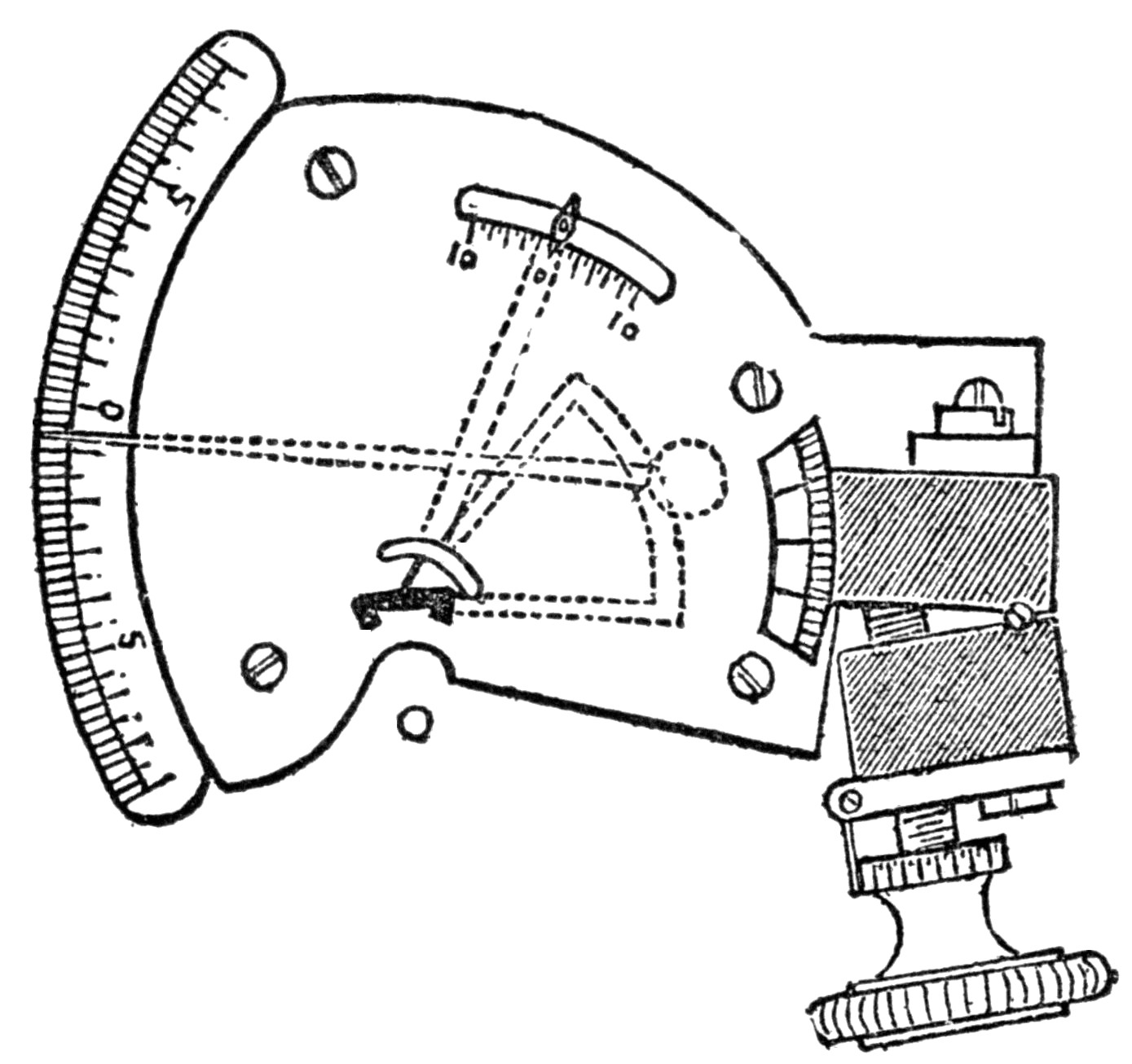
Fig. 258.
575. To Measure the Lift and all other Angles, etc. of the Lever Escapement. A very simple instrument for measuring these angles was designed by Curzon, one which any watchmaker can arrange for himself, and is quite sufficient for all practical purposes. This is shown in Fig. 258, and consists of an ordinary depth tool to which a scale is added. A hand adapted to the pallet-staff supported between one pair of runners of the depth tool gives motion to a curved rack (shown by dotted lines), and this causes a pinion carrying a second index to rotate, the radii being so related that the movement of the staff is magnified four times on a scale which can be observed while the glass is at the eye examining the pallets. The index which travels over the shorter scale to the left (divided up to 10° on either side of zero) is connected with the pallet-staff by a fork and a short arm passing through the circular groove; it affords a convenient means of moving the pallets while testing them, and gives a measure, in degrees, of their motion. The graduated arc shown at the top is for measuring the lever and roller.
576. Verge Pallets: to Measure their Opening. The little instrument shown in Fig. 259 may be used for this purpose; its mode of action will be easily understood from an inspection of the figure.
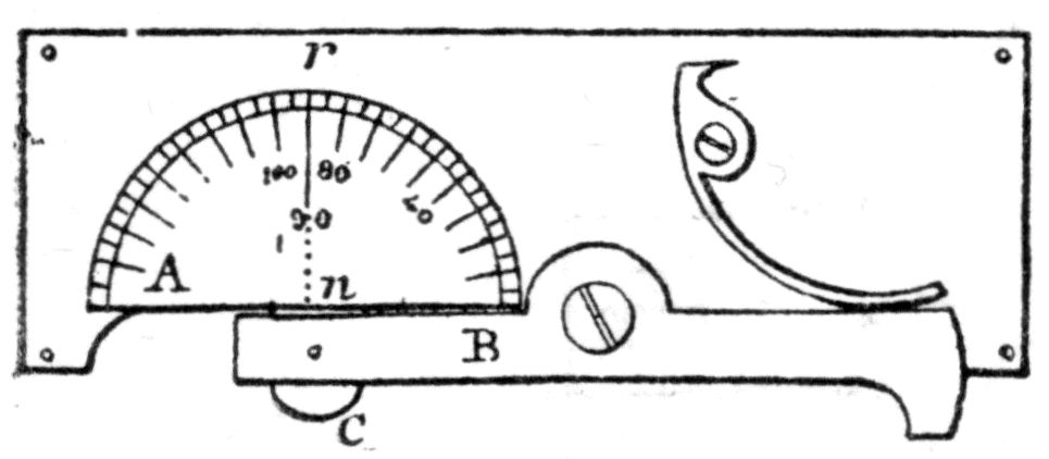
Fig. 259.
One of the pallets being held with its flat face against the base of the graduated semicircle by the lever and spring B, so that the axis of the verge is at right angles to the plane of the instrument through the point n, an index previously fixed to the other pallet will show by the graduations the number of degrees of opening.
This index, shown at P, Fig. 160, must be very light. It is formed in two parts, the body c d, and the small spring z z. The pallet when held in the notch c, must have its face held flat against c d by the spring z z. The face c d of the index must be quite smooth and straight, so as to avoid any error in the reading of the scale.
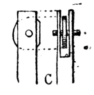
Fig. 260.
The pressure-block C, Fig. 259 (shown in plan and elevation at C, Fig. 260), is movable on its center, and this center, which by an engraver’s error is represented on the line n r, should be a little to the right of that line.
577. To Open or Close Verge Pallets. Some workmen cut a notch at the end of a small rod in which the verge is inserted, the two arms of the fork being then drawn together by a screw; then, holding each pallet in a pair of long-nosed pliers, one in each hand, the rod is held in the flame of a lamp and, as soon as the body of the verge becomes blue, it is gently twisted to the right or left according as the pallets require to be opened or closed.
This method is not always convenient, and the following may be recommended:
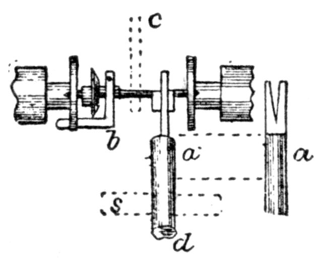
Fig. 261.
Support the verge by its shoulders between two cone-plate centers in a pair of finishing turns, as seen in Fig. 261. A carrier b is screwed to the upper pallet, and prevents the verge from rotating; c is a rod through which heat is conducted; a, shown both in plan and elevation, is another rod, which is much longer than c, and has a notch cut at the end, so that it can be forced on to the lower pallet. The end d is free, and the T-rest shown dotted at s, must be brought nearly into contact with it, the distance between them corresponding to the angle to which it is required to alter the opening of the pallets. Now hold a lamp under the free end of c and, as soon as the body of the verge changes color, d will descend by its own weight until arrested by s, the opening will thus be increased or diminished to the requisite extent.
The operation will be accomplished more quickly by directing the blow-pipe flame against the verge body.
Of course when diminishing the opening, the verge must be held in the reverse direction to that shown in the figure.
CYLINDER.
578. To Polish the Cylinder Lips Mechanically. The polishing of the lips of a cylinder is one of the most delicate operations that can be undertaken by a watchmaker; we have, therefore, endeavored to devise an instrument by which this can be done mechanically, and which should at the same time be so simple and so easily made that any watchmaker should be able to construct it for himself.
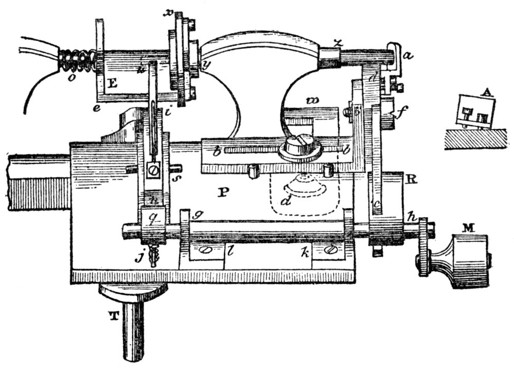
Fig. 262.
579. It consists of two distinct parts which take their place in an ordinary pair of finishing turns. 1. The plate P, Fig. 262, supported on a rod T, to take the place of the T-rest. 2. The frame E, whose axis replaces one of the runners. This much being clearly understood from the figure, there will be but little difficulty in understanding the following details.
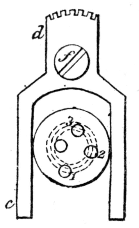
Fig. 263.
On the plate P is mounted a bracket, b b b′, held by a screw and washer. It has a slot cut lengthwise, so that on loosening the screw it can be made to slide towards the right or left. The vertical portion b′ supports a fork-shaped piece, d c, a front view of which is given in Fig. 263, pivoted on a collet-screw, f, and this may be fixed by a pin passing through its end like a bolt. The upper end of the fork-piece is provided with teeth for a purpose that will be presently apparent.
The long spindle, g h, turns between the two supports, k, l, fixed to the plate P, under the action of the handle M. This axis carries two eccentric cams, q and R. When it rotates, the eccentric R causes the fork d c to rise and fall, thus occasioning an oscillating movement of the rack d, at the same time the other eccentric q presses against the back of the slide i n, which moves freely in the guide s, and is always held against the cam by a helical spring j; the slide thus has an oscillating motion in the direction of its length.
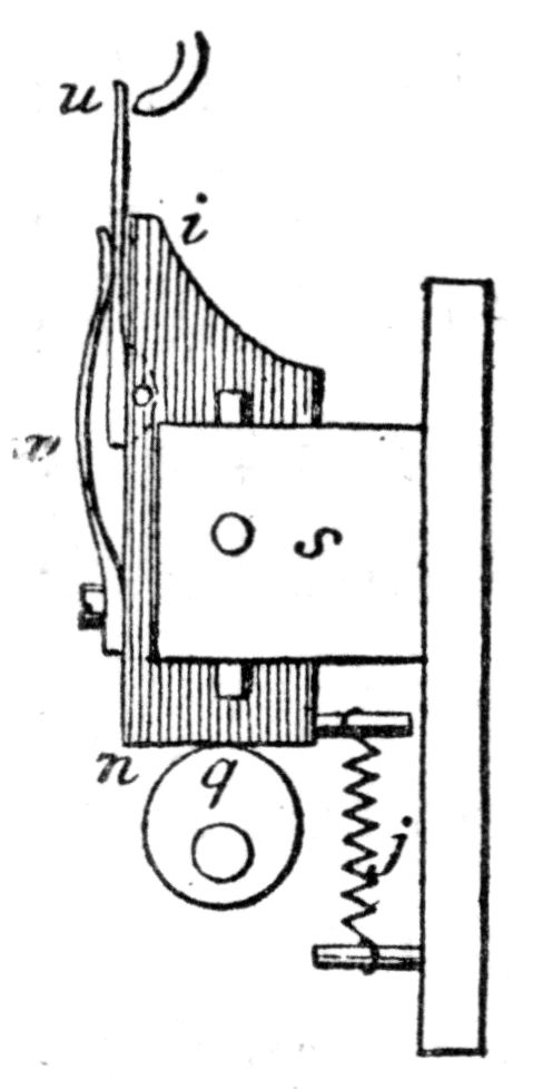
Fig. 264.
All the details in regard to the slide and its guide will be easily gathered from the plan in Fig. 262, and the side elevation in Fig. 264.
A small iron polisher is adapted to the slide n i. Being pivoted on a pin at one extremity, serving as an axis, its end u is pressed downward by the light spring v (Figs. 262 and 264), which might be replaced by a spiral spring below the polisher if preferred.
580. This being understood, we will pass to the frame E.
The rod that carries it is formed of thick drawn steel pinion wire, the diameter of which is less than that of the hole in the poppet-head of the turns. This spindle is provided with brass collars at y and z of such an external diameter as to be received in the poppet-head, in which the rod can rotate freely. By adopting this arrangement, not only is the frictional surface diminished, without reducing the accuracy of the adjustment, but the apparatus can be easily adapted to any pair of turns.
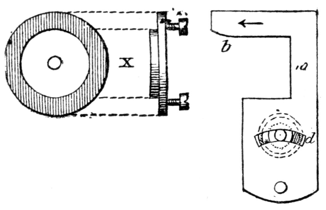
Fig. 265.
To the right-hand side of the frame is fixed, by two screws, the cylinder carrier x shown at X, Fig. 265. It must be removed in order to set the cylinder in position by cementing its balance to the surface; care is necessary to make sure that the back of the cylinder shall be towards the side e of the frame when the carrier is again screwed in position. After having thus replaced it, set the rack d to engage with the pinion wire z, in such a manner that, when the eccentric cam R occupies the position indicated in Fig. 263, the small iron polisher rests at the middle point of the cylinder lip. Now finally clamp the screw that fixes the support T.
The mode of action of the machine will be easily understood. If, after charging the polisher with polishing rouge the handle M is rotated, the cam R will impart an oscillating angular movement to the frame E through its axis y z, and the cam q will, at the same time, cause the polisher to move backwards and forwards, always in contact with the surface of the lip during its movement.
581. The work will be performed more rapidly, and the polish will be better if the iron have a slight lateral motion as well as that in the direction of its length. It is, however, more simple to communicate a longitudinal oscillating movement to the cylinder, and this answers the same purpose; it is only necessary to make two small additions, the spiral spring o and the little cock a. The latter is fixed to d in an inclined position (as indicated at A), and this inclination can be varied by merely turning the left-hand screw. It will be evident that when d is ascending, the cock will push the spindle y z forward; and when d descends, the spindle will be brought back to its initial position by the pressure of the spring o, which is simply placed over the end of the opposite runner. This longitudinal movement must be but slight, and it can be made as little as desired since it depends solely on the inclination of a.
582. Observations. 1. The angular motion of the frame E must be sufficient to enable the polisher to act on the entire surface of the lip. The extent of this movement is determined by the size and the degree of eccentricity of the cam R. The greatest motion will occur when the spindle passes through the hole 1 (Fig. 263), and it will gradually become less as the holes 2, 3, etc., are used. The cam q should also have two or three holes for varying its eccentricity. These cams may be made of hard wood, ivory, etc.
2. The iron polisher may be replaced by a piece of flexible spring fixed by a screw to the slide; but its pressure is less uniform.
3. The bent arm w, Figs. 262 and 265, is clamped to the plate P by a screw d, and the long arm b, Fig. 265, bears against the back of the poppet-head, and thus ensures the steadiness of P. To insure steadiness by its means, b is drawn back in the direction of the arrow, then hooked behind the poppet-head and clamped by the screw d. The firmer the support is the better.
4. The machine may be arranged so that the two lips can be polished at the same time, but it then becomes more complicated. In the tool here described, as soon as one lip is polished the cylinder carrier is unscrewed, turned around, and screwed against the left arm of the frame E, in which are two screw-holes opposite to those in the right-hand arm. Unscrewing the slide b b, the T-rest carrier is moved along the lathe bar until the polisher is over the lip; b b having been set in position is clamped, and, after seeing that w has a bearing, the second lip may be polished.
5. The cylinder carrier shown at X, Fig. 265, is used when the balance is in position. For a plain cylinder without its balance another form of carrier is employed that has at the edge of its central hole a small but solid projecting shell to which the cylinder is cemented.
583. Methods of Obtaining Continuous Motion. Rapid work is not possible when a single handle, as shown at M, is used for working the apparatus; recourse may, however, be had to one of the following methods:
1. Mount a small pinion with a square hole at its center, and make it engage with a large wheel driven by a handle. This wheel, having a great number of teeth, will proportionately increase the rate of motion.
2. Take a powerful clock movement and connect up its center arbor with the axis g h; having wound up the main spring, allow it to run down so long as it possesses sufficient power to drive the mechanism.
3. Fix a ferule at h, and drive it by the aid of a foot-wheel.
BALANCE SPRING.
584. To Select a Balance Spring. Various methods are adopted for this purpose. The most common, by which the strength is ascertained from the length of cone formed by hanging the balance from the inner coil of the spring while the outer is held in a pair of tweezers. A more exact method, based on the same principle, is to employ the small gauge shown in Fig. 266.
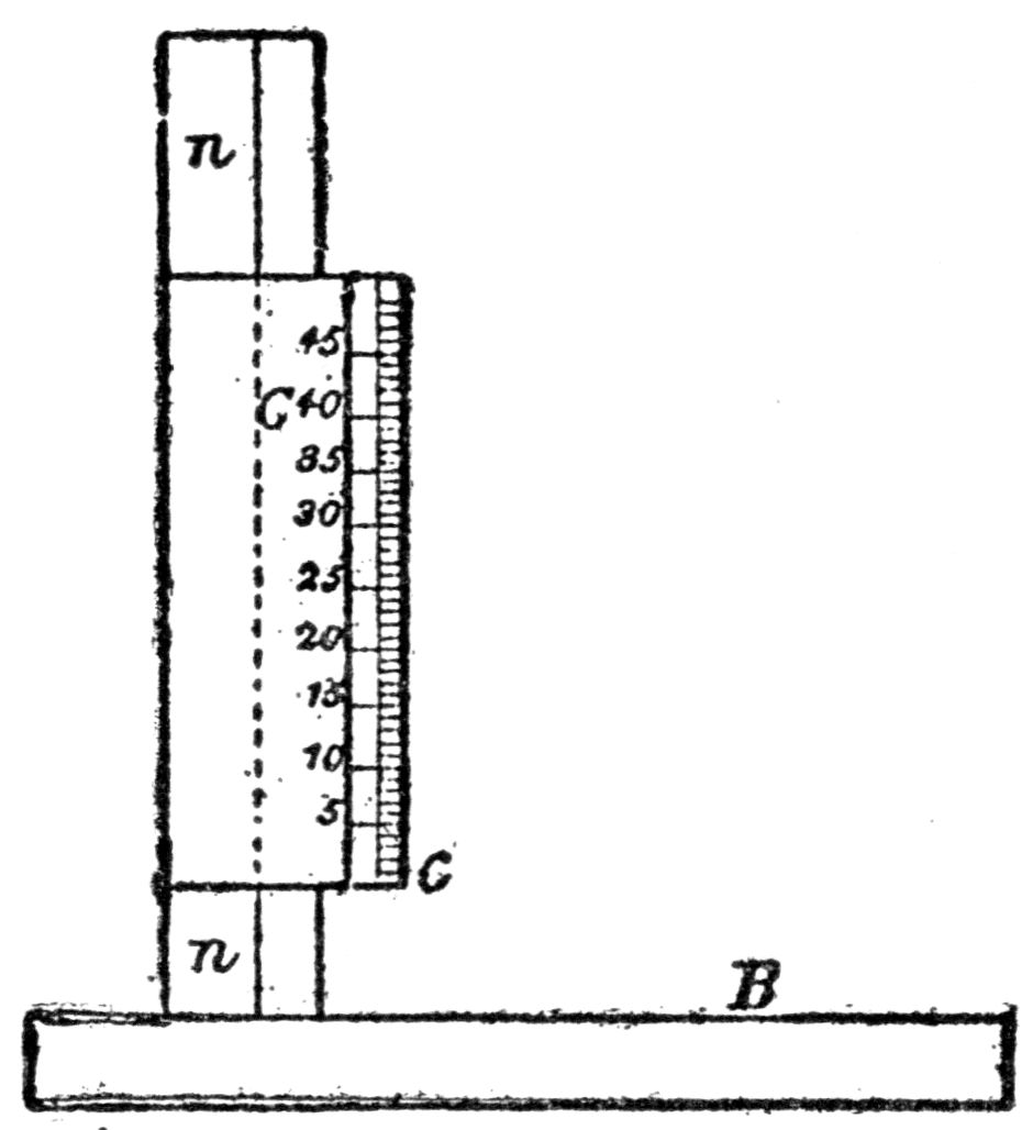
Fig 266.
A vertical pillar n n is fixed on a smooth plate B, and the slide C is held by friction in any position on n n. Place C so that the distance between c′ and B is equal to the distance between the end of the lower balance-staff pivot and the balance-spring collet. Having now fitted the spring in this collet, raise the balance, by tweezers holding the outer coil, until the lower pivot just rests on B. The graduations on C will then afford a measure of the extension of the spring, and this extension should about equal the radius of the balance measured on the same scale.
When the number of vibrations performed in an hour is known, a spring may be selected by fitting it to the balance and, while holding the outer coils in the tweezers, supporting the lower pivot on a hard smooth surface; the balance is then made to vibrate and the vibrations are counted. The spring need not be pinned into the collet, but may be attached by wax to the top pivot.
585. To Fix a Balance-Spring to its Collet. A common way of doing this is to put the collet on a wire or broach which is held in one hand while the other presents the inner end of the spring, held in tweezers, to the hole in the collet; subsequently fixing it with a pin. The following is a more convenient method:
At the middle of a brass plate is a boss tapped through a vertical hole in its center to receive a small screw with flat head. When the collet is fixed by this screw passing through it, the operation of setting the spring in position and pinning it will be much facilitated, and the plate will at the same time afford a means of testing its parallelism. Two or three screws with heads of various sizes should be provided, and, in order that they may be always available, they should be screwed into holes at a corner of the plate.
This tool might be made of further use by adding an arrangement for holding the stud while drilling it, with a view to ensure that the hole is at the proper height.
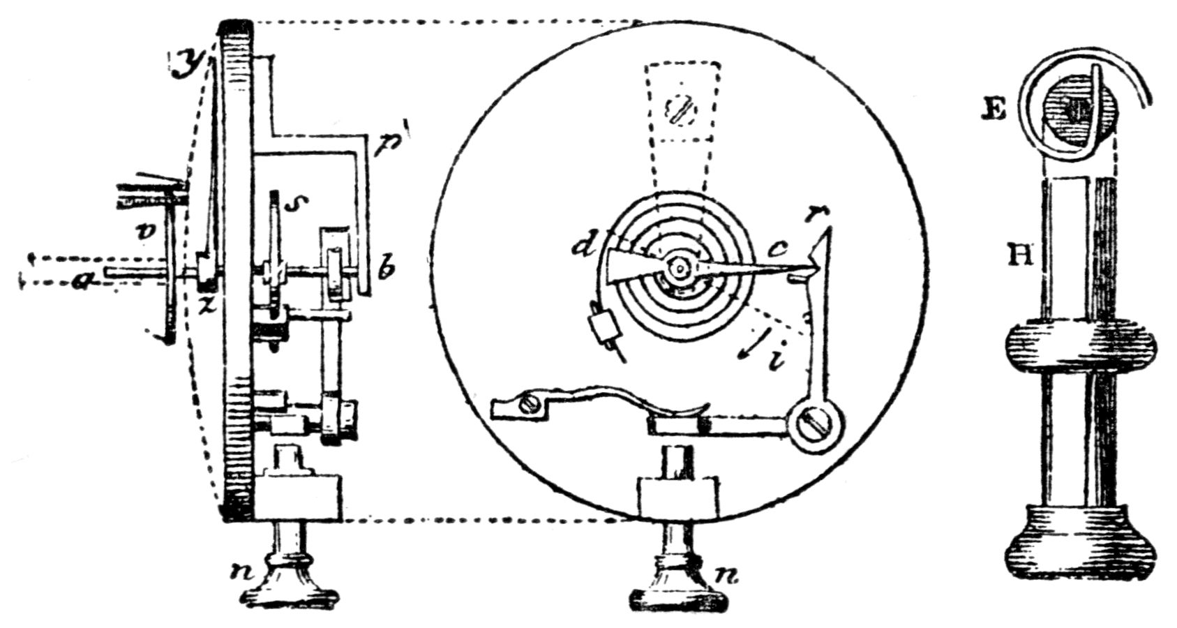
Fig. 267.
586. Balance-Spring Gauge. A back view and side elevation of this are shown in Fig. 267; it can be made without difficulty by any watchmaker.
Through the middle of the plate passes a staff a b lightly pivoted between the cock p and the plate, and projecting on the left-hand side as far as the point a. Between the cock and plate it carries the collet of the spiral spring s and the stop-finger d c, and at the point z is a light finger y z that passes over the graduations on the dial.
When the stop-finger d c is free it stands in the direction of the dotted line i; on rotating the staff, by taking hold of the pivot a, in the direction of the arrow i, the extremity c of the finger will be brought round till it presses against the inclined plane r, which it will force back and, on coming against the stop near c, it will be held fast in the notch of the small bent lever that terminates at r. A spring maintains this lever always against a pin set in the plate. The index finger y z will now be standing over the zero of the scale, and will be maintained in that position until the finger d c is released by a momentary pressure of the hand on the push-piece n, when it will fly back to the initial position corresponding to the dotted line i.
587. The instrument is used as follows: The small sliding holder H, which is shown in section at E, (both of these figures being much enlarged since it is extremely fine and light), has a hole through its center that fits on to the axis at a. Having set a balance spring in the clip as indicated at E, place H on the pivot a, tightening the slide so that it can be used to rotate a b, and bring the stop-finger round to the position d c. Holding the outer coil of the spring in tweezers at v, its inner coil being held in the clip, release the bent arm by means of the push-piece n. The point on the dial at which the finger y z is arrested will give a measure of the force of the balance spring v.
It will be evident that a spring can now be easily selected of the same strength as v, or stronger or weaker within definite limits which will become well known when some use has been made of the instrument.
The entire mechanism is enclosed within a box that is covered by a glass, through the middle of which a hole is made for the passage of a. The spring s is of about the strength ordinarily used for 18-line watches.
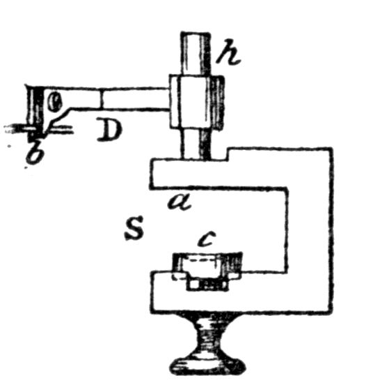
Fig. 268.
588. To Set a Breguet Spring in Position. To test the strength of a flat spiral spring that is to be formed into a Breguet spring, it must first be attached by its collet to the balance-staff. As the outer coil cannot be held in the stud owing to its being so near to the pivot hole, it must be held in the clip b of the little appliance shown at S, Fig. 268. Holding the watch-plate between a and c, the arm D can rise or fall on the rod h, and b can be brought to such a position that it grips the spring at a point just beyond the stud, so that, when the spring is turned inward, the point held may be brought up to the stud. The springing of the watch can thus be proceeded with, and springs tried until one of the required strength is obtained. It then only remains to give the spring the double curvature, and to take care that the end of the overcoil is brought sufficiently near to the center.
Since the action of a Breguet spring is more free than that of an ordinary flat spring, the watch may be found to lose slightly; it is advisable therefore to time the watch before making the bend, so as to show a gain. A little experience will enable the watchmaker to avoid being much out, and any trifling error that there may be is corrected either by a displacement of bend or by altering the central coil. If the latter method is to be resorted to, it is better that the watch should lose rather than gain a little.
589. To Flatten an Ordinary Balance Spring. Remove the collet and stud, and clamp the spring by a central screw between two plates, which are then placed on a blueing tray and gently heated. A small piece of whitened steel is laid on the plate in order to see that the heat does not exceed what is needed to give a blue temper. Allow the plates to cool and separate them.
Ordinary springs being made of rolled steel and subsequently coiled, always open out on heating; it is therefore necessary before resorting to the above method, to coil up the spring, as otherwise the outer turn will be found to have opened beyond the stud.
590. To Diminish the Strength of a Balance Spring. Scraping the end or the entire length always renders the spring defective. Dipping in acid is very little better. It is preferable to embed the spring in cork or soft pith, and work it over a ground glass plate covered with oil stone dust that is fine and smooth. This method might be resorted to for reducing the height of a mainspring.
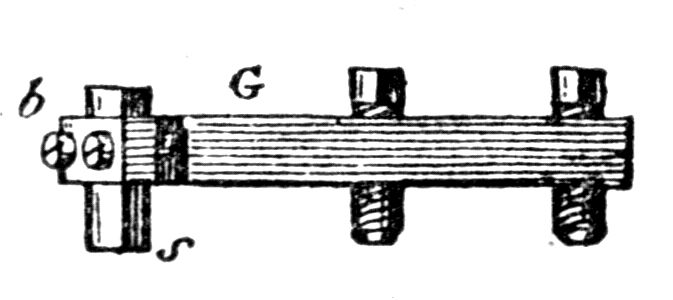
Fig. 269.
If the cork or pith is hard and only a little metal has to be removed, the operation is successful; but it is apt to result in more metal being removed from the edges than from the center. When much has to be removed, the spring must be cemented to the polishing plate (shown at G, Fig. 269, and described in article 345) with fine wax, thoroughly liquid, so that on pressing the spring all its coils may come in contact with the plate; it must be held thus until cold. Now adjust the leveling screws, so that the whole surface bears flat on the glass; rub it as long as is considered necessary, and detach the spring as soon as the plate is sufficiently heated; boil in alcohol to clean its surface.
591. To Harden Gold Springs. Gold detent, thermometer, suspension and balance-springs can be obtained of a high degree of elasticity. Rolling hardens them, but renders them very brittle. They can be made supple and elastic, not by hardening, as in the case of steel, but by annealing, care being taken not to exceed a certain degree of heat. The spring may be coiled on a block and placed in a tube that has a smooth steel lid, then heat the tube in the flame of a spirit lamp, and as soon as the steel is of a blue temper, remove the flame and allow the whole to cool.
Others anneal by keeping the spring in boiling oil for a definite period.
The hardness of a gold spring increases with the proportions of alloy it contains, and, if well annealed, it will be very elastic and will break when bent too far, as in the case of steel.
592. To Ease an Index on Its Endstone Cap. It is a common but bad practice among watchmakers to scrape the inside of the ring of the index or to cut it through. A better method is as follows: Resting the index on a cork, cover the inside of its ring with oil stone dust and make the cap rotate in its seat by means of a pinion calliper, the two points of which are inserted in the screw-holes. The operation is repeated as often as may be required.
DIAL PLATE.
593. To Cut the Large Hole in the Timepiece Dial Plate. Some workmen cut the hole in the dial-plate of a timepiece by means of a strong pair of compasses, one leg of which terminates in a bullet-nose that is supported in a central hole, while the other is provided with a hardened cutting point that serves to scrape out a groove.
Others use a rule that revolves on a conical point and carries a slide with a tracing point which can be replaced by a sharp-pointed cutter. Proceed in exactly the same manner as when using the compass, but a greater force can be applied, because, while one hand steadies the center, the full force of the other is applied to the cutter.
A third and still simpler plan is adopted by some clockmakers. A rod of the diameter of the central hole, and a cutter of which only the cutting point projects, are gripped in a vise at a distance apart equal to the radius of the hole to be made. Then passing the rod through the central hole and holding the plate in both hands, rotate it, at the same time applying pressure so as to cause the cutter to form a groove. When a moderate depth has been attained, invert the plate and cut one on the opposite side. Care is necessary when the grooves are on the point of uniting; on the removal of the center, smooth the edge with a half round file. Some workmen consider it more convenient to set the cutter and rod in a thick piece of wood that is rounded at the top and made flat on its two sides towards the bottom, so as to be firmly held in the vise.
594. To Drill an Enamel Dial. Take a hard, well-sharpened graver and moisten it with turpentine or turpentine that contains camphor in solution, or in the following mixture, which is still better:
Turpentine 62 parts by weight.
Oxalate of potassium 4 ” ”
Camphor 4 ” ”
The two latter substances are reduced to powder and dissolved in the turpentine, and two parts by weight of sandal wood may be added.
The graver point is placed on the dial at the point at which a hole is required and the graver is rotated backwards and forwards between the fingers. Practice, acquired by drilling a few holes in broken dials, will soon indicate the degree of pressure that can be applied without fear of accident. Some workmen prefer only to apply the maximum pressure while the graver rotates in one direction, reducing it during the opposite movement; others hold the handle or tang in one hand and rotate the graver with the other, always in the same direction.
The operation is continued, frequently arresting it, however, in order to set the graver and moisten it, until the copper-plate and back enamel are perforated.
As soon as this point is reached, take an iron or steel spindle, pointed at one end. The point must be more obtuse than the hole already formed in the dial. Charge this end with emery or oilstone dust, and place in the chuck in your lathe; when the spindle is caused to revolve the enamel on the contour of the hole will be rapidly removed. When the copper disc is reached, a fine-pointed and sharp graver must be used to remove the metal that is exposed as well as that which is covered with only a thin layer of enamel; then renew the operation with the spindle, occasionally drawing a file along the surface of the acting cone. Or the cones of solid emery to be obtained at material stores can be used for this purpose. A workman must be very careless or unskilful to fail in rapidly drilling a hole in a dial by this method without accident, and he may carry on the process easily until the hole is large enough to permit the introduction of a rat-tail file.
595. To Enlarge a Dial-Hole With a Rat-Tail File. As an extra precaution the contour of the hole on either side may be coned with a spindle as explained above, so as to reduce the thickness of enamel to be acted upon by the file; but a watchmaker that has had any experience can dispense with such a preliminary, which we would at the same time recommend.
The file must enter the hole freely. If only the point can do this, the file must be held very short, so that the finger may come in contact with the dial before the larger diameter of the file locks in the hole, as this would almost certainly crack the enamel. Some workmen avoid such an accident by forcing on to the file a rather long cork of small diameter.
With a view to avoid scratching the face of the dial in case the file is drawn out of the hole in its backward movement, it is well to round off and polish its point.
During the forward movement a slight circular motion is given to the file, and in returning no pressure is to be applied; the file must merely slide over the surface. It is dipped from time to time in the liquid mentioned in the last article. When the hole is large enough, a conical spindle should be used to smooth its edges as in the earlier stages of the process.
596. To Remove Enamel from the Back. To remove portions of the enamel from the back when it touches part of the motion work, etc., various methods are adopted.
The little spindles of solid emery that may be obtained at material stores may be used for the purpose.
Some watchmakers use a flattened lead ball perforated at its center and carried on a taper arbor, forming a kind of small grindstone, rounded across its rim. The arbor is held in a chuck and the edge of the lead disc is moistened with water, and emery powder sprinkled over it; when set in rotation the surface to be removed is held against the lead, the necessary pressure being applied by the finger against the other face. Water must be frequently sprinkled on the surface so as to avoid heating, and to maintain the emery in its place, and the dial is washed occasionally to examine the progress of the work.
In place of lead, some use emery formed into a solid block with shellac or various kinds of cement; it is centered on a large taper arbor, and should be at least a quarter of an inch thick and rounded at its edge. Such a disc is very hard when cold; it is used in the manner explained in the last paragraph, but wears more rapidly than the lead disc, if the latter is well made and supplied with emery of the right degree of coarseness, in sufficient abundance and evenly distributed.
597. Dials Fixed by Screws through the Edges. The screw-holes at the edge are drilled in the manner already explained in article 594, and the center hole is enlarged as there described, if this is found to be necessary in order to permit the free passage of the hour wheel. The diameter of a dial may be reduced if it is too large in the manner explained in article 600. When it has been thus prepared, place it in position, the XII being exactly opposite the pendant, with the movement in the case, and close the bezel. If the dial is found to shake under the bezel it should be fixed with three or four small wedges of pegwood, care being taken that they do not subject the dial to much pressure. The accuracy of the position may be tested by holding a stretched piece of cord over the dial, and observing whether it passes at the same time through the middle of the pendant, the center hole, the XII and the VI. When the dial is thus found to be properly placed, mark one of screw-holes on the watch-plate through a dial-hole. Some care is necessary in doing this lest the hole is marked eccentrically or the dial is displaced by pressure against one side of the hole in it, which might result in the dial being cracked by the screw. Now remove the plate from its case and drill its screw hole in the drilling tool; tap it and fit the screw. Replace the plate in the case, and, after fixing the dial to it with the one screw thus fitted, carefully mark the second hole, etc.
Some workmen expedite the operation by marking and drilling the two holes at the same time; but if at first they do not succeed in making them in the required position they materially increase the time occupied, as one hole at least requires to be bushed, etc.
598. Dials Held in Position by Feet. If the dial has feet, and it is required to adapt them to the plate, they must be first carefully bent straight; then take a piece of stiff card board of moderate thickness, and laying it on a piece of lead, punch out with a sharp-edged punch, or other means, a round hole of the diameter of a foot. Having inserted one foot in this hole, and placed the card on a flat surface with the dial uppermost, apply a slight pressure to this latter so as to mark the position of the second foot. Then punch out a second similar hole at the point thus indicated. If the operation has been properly conducted the two feet will enter the holes easily, but at the same time without constraint or shake, and they should project on the opposite side.
It now only remains to cut out the cardboard to the size of the plate, and, after making a central hole and a mark to exactly correspond with noon, to place it in position in the frame and under the bezel, as though it were the actual dial. Then mark the two holes for the dial feet, using a sharp-pointed chamferer that just fits the hole, held vertical and rotated by one hand, while pressure is applied by a finger of the other hand.
Some workmen merely prick holes in the card with some sharp-pointed instrument, or even force the feet through it at all risks; hence it happens that feet are often bent out of the vertical, and, in order to be able to bend them into the required position, it becomes necessary to enlarge the holes in the plate and bend the dial feet.
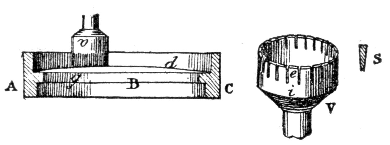
Fig. 270.
599. To Cut a Large Hole in a Dial. To set a Seconds Dial. This operation is performed in the ordinary lathe. The hole is cut by a ring of thin iron or copper cut with saw-like teeth round its edge, as shown at V, Fig. 270, kept in rotation and charged with fine emery and oil or water or, what is better, turpentine. The mixture described in article 594 will secure a still more rapid action.
It is advisable that the thickness of the ring be made to gradually diminish from e towards i, as indicated by the section at S, so as to prevent it from choking and probably cracking the dial.
The following arrangement may be adopted: Prepare a strong ring with a projecting internal ridge, shown in section at A B C; cement the dial, g d, to this ridge, or fix it by any convenient means, and attach this supporting ring to a chuck that rotates in a direction opposite to that of the cutter, but much less rapidly. On reaching the copper disc, reverse A B C and repeat the above process on the back enamel. The copper is thus exposed on the two sides. On filling the deeper groove with dilute nitric acid the metal will gradually be eaten away, and the acid should be renewed as often as may be needed. It then only remains to smooth the edge, beveling it on the front side, and to cement the seconds dial in position.
The use of acid may be avoided and the cutter passed through the copper, but greater care must be exercised, because the work is more difficult when operating on metal. It will, however, not be difficult after a few trials.
Willis recommends that the dial be cut straight through, commencing at the back and using emery and oil, the dial being cemented on a brass block immediately below the cutter, and rather less in diameter than the hole produced. He mounts the cutter on a stock that is provided with a pump center, the point of which is maintained throughout the operation in the small hole or point that marks the center of the hole. The great advantage of this method is that the taper of the hole is in the required direction and no filing is necessary.
600. To Reduce the Diameter of a Dial. Resting the dial in an inclined position against a block, file its edge with a smooth or half-smooth file, which must only be allowed to act while advancing, and is at the same time displaced sideways and turned so as to follow the contour of the dial. The file should be dipped occasionally in turpentine, and when sufficient enamel has been removed, pass a new emery stick over it to remove the file marks.
601. To Remove a Figure or Name from a Dial. Oil of spike lavender may be employed for erasing a letter or number.
Enamel powder made into a paste with water, oil, or turpentine, is also used for this purpose. It should be previously decanted so as to obtain several degrees of fineness. The powder used for re-polishing the surface where an impression has been removed must be extremely fine. It is applied on a piece of pegwood, although some use ivory.
The last and best system is to use diamond powder. Take a little of the powder, made into a paste with fine oil, on the end of a copper polisher, the surface of which has been freshly filed and slightly rounded. On rubbing the marks they will be seen to rapidly disappear.
The surface is left a little dull; it may be rendered bright by rubbing with the same powder mixed with a greater quantity of oil and applied with a stick of pegwood.
Watchmakers will do well to try several degrees of fineness of the diamond powder on old dials.
METAL DIALS.
602. To Restore a Silver Dial. We proceed to describe several methods of doing this, but would at once observe that when the earlier ones are adopted, the hours, if they are painted, necessarily disappear; whereas they can be retained by resorting to the last method although great caution must in that case be taken; moreover, it is much more difficult to accomplish than the others.
603. First Method. This is the most expeditious system, and at the same time the most certain of success.
If the hours are in enamel, there need be no fear; if engraved and filled with black composition, this will disappear, but it can be replaced without difficulty. There remains the case of painted hours to be considered.
First make thin marks with a fine point along the lines of all the figures, taking care not to pass beyond their ends: and do the same for the dots and lines that indicate the seconds. By using a glass and following the instructions given in article 619, no difficulty will be experienced in doing this, and the fine lines and dots thus made will afford sufficient guide for re-marking the hours.
Begin by cleaning the dial with a brush and fine pumice-stone so as to remove spots and slight scratches.
604. To Frost the Surface. In order to frost the surface of the dial, take a spirit lamp with large wick, and direct a blow-pipe flame from it against the under side of the dial, which is held by one hand with a hooked support. If the flame is gently directed over the entire surface of the back, a good dead surface is obtained that resists a moderate degree of friction either in soaping with a fine sponge, or washing in a large quantity of water, or in applying soft bread and oil of spike lavender to erase irregularities or marks made in painting the figures.
The application of the flame is several times repeated, so as to obtain a decisive and even frosting; but it is necessary, with a view to avoid buckling the thin metal, to place an iron or copper washer behind the dial. The flame oxidizes the surface of the metal; that is to say, it causes the oxygen of the air to combine with the copper which is alloyed with silver.
605. Pickling or Bleaching the Dial. Introduce sufficient warm water into a suitable flat vessel to completely cover the dial, and gently pour into it a few drops of sulphuric acid (oil of vitriol), so that the two liquids are in the proportion of about 1 to 10; then lay the dial in this dilute acid for a period that varies from half to one or two minutes. The frosting will first become yellow and then of a beautiful white color. Wash it in a large quantity of water, wipe with a fine linen rag, and apply the flame momentarily to the back in order to prevent the formation of spots on the surface.
When several dials have to be operated upon, the acid is put in a porcelain dish and boiled by a lamp. Then place each dial for a moment in it, wash in an abundant suppl of water, and dry by tapping with a fine linen rag.
606. Second Method. For the benefit of such as care to experiment with it, we add the following method: Brush the dial with a coarse brush and pumice-stone reduced to an impalpable powder until no scratches are visible. Make it red-hot and allow to cool. Then dip for two or three seconds in a porcelain vessel containing dilute sulphuric acid; on removal it will be found to be white, but rather dull. In order to produce a clear frosted surface, place the dial in a mixture of
6 parts by weight of nitric acid of 1.22 sp. gr.[8]
21 ” ” sulphuric acid.
50 ” ” water.
Allow the metal to remain in this acid until no more globules are seen to form on its surface, then withdraw it and immediately place in cold water. The dial will be observed to be nearly black; it is then pickled as above explained (605), washed well, heated red-hot and, when cold, again pickled; the operation is concluded by thoroughly washing its surface.
607. Third Method.[9] Cover the surface of the dial with a thin layer of soap, and brush it over, taking care to avoid touching the hours if these are not enamelled. This can best be done with a fine brush and pumice stone reduced to an impalpable powder. When the dial has been made as clean as possible by this means, wash it carefully with water and tartrate of potash (cream of tartar), then plunge it immediately in the hot solution of nitrate of silver (608) attaching it to the silver wire which is fastened to the zinc and copper discs 609; in two or three minutes the surface of the metal will be perfectly frosted, and, if each operation has been cautiously performed, the hours will remain intact.
Each time the zinc and copper discs are used they should be cleaned with nitric acid, and rubbed over with pumice stone. As soon as the dial is clean, immerse it in the solution; the least delay is apt to cause the surface to become oxidized through contact with the air.
608. To Prepare the Silver Solution. Dissolve an ounce[10] of solid nitrate of silver (lunar caustic) in a small quantity of water; filter the solution and add twice its volume of liquid ammonia. In a separate vessel dissolve 6 ounces of yellow prussiate of potash and 4 ounces of crystallized carbonate of soda in 60 ounces of water, contained in a vessel of enamelled iron, which must be placed on the fire. When near the boiling point add the concentrated solution of nitrate of silver, and allow the mixture to boil for an hour, taking care to add hot water in sufficient quantity to make up for that lost by evaporation; then filter the resulting solution.
609. To Prepare the Discs and to Plate. In order to use this solution for restoring a dial or plating any other object, take two discs about the size of a half dollar, one made of zinc and the other of copper, and, after making a small hole in each, unite them with a copper wire, or, preferably, with one of silver. After having attached the dial or other object to this connecting wire, immerse the entire system in a glass or earthenware vessel, and pour over it a sufficient quantity of the solution, previously made hot.
If the object operated upon is perfectly clean, bright and free from all greasy or oily matter, its surface will be found in two or three minutes to be covered with a firmly adherent layer of silver. When only a small piece is treated it will suffice to immerse it in the hot liquor, and rub it with the finger; a bright silvered surface will thus be obtained.
610. To Clean Metal Dials of Clocks. When the hours are neither enamelled nor engraved, it is necessary to first trace out the several lines and dots in a manner similar to that explained in article 619.
611. Ordinary Mode of Cleaning the Dial. Very often it is possible to make a silver or plated dial of either watch or clock sufficiently clean by merely brushing with powdered cream of tartar worked into a paste with water, carefully rubbing around any painted figures with a fine stiff brush. Then wash with clean water, dry by gently tapping with a fine linen rag, and expose to a slight heat. (This is in part the same method as is described in article 607; the two may be combined). If the dial is tarnished, it must be silvered as explained below.
612. To Plate a Brass Dial. Preparing the Silver. Place in a glass flask from 100 to 150 grains of pure silver made into thin strips by means of a hammer or rolling mill. Add five or six times the weight of dilute nitric acid so as to completely cover the silver, and warm the vessel, taking care to avoid breathing the fumes or admitting them to the workshop. The metal will be dissolved, and, on continuing the application of heat until all the liquid is evaporated, crystals will be found at the bottom. When cool fill the flask with warm water and, as soon as all the crystals are dissolved, pour the solution into a porcelain dish, previously half filled with water. Place in it a sheet of clean copper of about the size of three fingers, and allow it to remain for the night.
On the following day all the silver will be found attached to the plate, and it can be collected by immersing this in water. Carefully pour off the water from the fine powder thus obtained, and wash it once or twice with an abundant supply of pure water; then dry thoroughly with the application of very moderate heat. If the silver thus obtained is not required for immediate use, it should be kept in a dark blue bottle to avoid the influence of light and moisture.
613. To Prepare the Surface of the Dial. It must be quite smooth, thoroughly washed and dried. M. Robert recommends that the smoothing be accomplished by using soft water of Ayr stone, rubbing in all directions, in order remove scratches. Or pegwood charcoal can be used, sloped at one end like a whistle, and applied with water. Others employ pumice-stone powder and very fine emery paper.
614. To Apply the Silver. Take equal parts of rock-salt and cream of tartar, pound them together, and when well mixed, take about 60 or 80 grains of the mixture, and add to it 15 or 20 grains of silver, prepared as above described, and add a few drops of water to form a thick paste, which must be well mixed and worked up on a ground glass plate by means of a horn spatula to remove all grits. A glass pestle may be used for this purpose.
The dial having been prepared, take up some of the paste with a perfectly clean and rather stiff brush, and spread it over the surface of the dial, rubbing quickly and somewhat harshly. The brush should be worked about in all directions, so as to avoid scratches, until the silver is found to adhere firmly to the dial. According to M. Robert, this rubbing is to be continued until the required grain is obtained; but M. Fournier states that it should be arrested when the surface possesses a lead-grey color; the dial is then well washed, dried, and the operation re-commenced exactly as before except that the brush used is softer. A good surface will thus be formed, and it will be whiter if the proportion of silver in the paste is increased.
The result attained in great part depends on the skill of the operator, and this can only be acquired by experience.
615. Observations. If the mixture contains too much of the salt or too little silver, the latter will adhere with difficulty, and will come off in lumps or scales; moreover, it will not have so white a color.
As the proportion of silver is increased, the white becomes gradually better; but, on the other hand, if it is in excess the surface will be coarse and uneven. Too much or too little water will have nearly the same effect. The color is worse if the dial has been imperfectly smoothed, and when several days or even hours are allowed to elapse between the cleaning and silvering.
It is essential that the rock-salt and the cream of tartar be perfectly pure; if they contain any earthy matter it will scratch the surface and impair its whiteness.
As soon as the operation is completed, the dial must be washed in an abundant supply of pure water; any neglect in this particular will cause it to blacken. This washing may be performed with an ordinary watch-brush, charged with cream of tartar. Then rinse the dial, and dry, tapping gently with a fine linen rag, and finish by slightly warming it.
616. Gold Dials. It will not be necessary to say much on this subject. In order to restore the color to a gold or gilt dial, it may be dipped for a few seconds in the following mixture: Half an ounce of cyanide of potassium is dissolved in a quart of hot water, and two ounces of strong ammonia mixed with half an ounce of spirits of wine and added to the solution. On removal from this bath, the dial is immediately immersed in warm water; then brush with soap, rinse, and dry in hot boxwood dust. Or it may be simply immersed in dilute nitric acid, but in that case any painted figures will be destroyed.
617. Another Receipt. The following is the method ordinarily adopted for coloring gold dials; but it is to be observed at the outset that, although apparently characterized by extreme simplicity, a good deal of skill is needed to ascertain when the mixture is of the right consistency, and when the dial has been sufficiently exposed to its action.
Make a mixture of 4 oz. saltpetre, 2 oz. alum and 2 oz. common salt (the purest attainable), with a very little water. On placing this in a blacklead crucible over the fire it will become limpid, and must be allowed to boil until somewhat pasty and of a pale yellow color, stirring all the while with a stick. Now take two dials, back to back, that have been cleaned and blackened by annealing, and pass a platinum wire through their centers so that they hang horizontally, resting on a loop at its end; immerse the dials in the hot color crucible, and, after holding it for a short time, withdraw them and immediately immerse in a vessel of nearly boiling water standing close by. The “color” will then be washed, and the progress of the work can be observed. The dials are again dipped in the crucible if necessary, and will probably require about three minutes’ immersion in all. It is advisable that the “color” be thick rather than thin, as in the latter case the dials are apt to be clouded.
618. To Re-Paint the Hours on a Dial. The following system has reference to metallic dials, but the reader will be able to select without difficulty the parts that are applicable to altering and retouching the figures on an enamel dial.
We can answer from experience for its being successful, but would at once observe that it cannot be practised hastily, because some skill is essential in addition to patience and care: with them, success is certain.
619. First Method. Before removing the hour figures and the divisions for minutes, mark them with a fine steel point, using a lens and proceeding with great caution. These marks will remain, so that after the dial has been colored or otherwise treated, it will only be necessary to trace over them with a fine brush charged with ink.
The short horizontal lines at the top and bottom of each figure, termed serifs, as well as the two circles that enclose the minute divisions, can be drawn with a sharpened point of the screw-bar compass.
620. Second Method. Lay on the dial to be treated, or on another of the same dimensions that has the hours well marked, a piece of tracing paper, so that neither it nor the dial can be displaced, and, using India ink and a fine drawing pen, accurately trace the hour figures and the minute divisions. When the ink is dry, invert the paper and trace the figures, etc., thus obtained on the other side of the paper, this time using a pencil instead of ink. Laying the paper on the dial so that neither can slip, pass with a rounded point of some soft metal over all the figures and divisions. Now remove the paper without permitting it to rub against the dial. If the pencil has been selected of a suitable degree of hardness, and the operation skilfully conducted, the marks showing the hours and minutes will be clearly visible, although faint, and, holding the glass to the eye, the several marks must be traced over with a fine brush or pencil. If this operation is performed carefully, the dial will present a very good appearance.
621. Third Method. Place the dial within a kind of large barrel that has at its center a thick pivot projecting. The three rules, D, F, J, Fig. 271, can be fitted on to this by their central holes so as to rotate on it. Being supported by the rim of the barrel, they will pass very near to the surface of the dial without rubbing against it. From an inspection of the figures it will be evident that D is used for forming the bars of an X, F for those of a V, and J for that of an I. Of course the serifs at either end of a numeral are made with the compass.
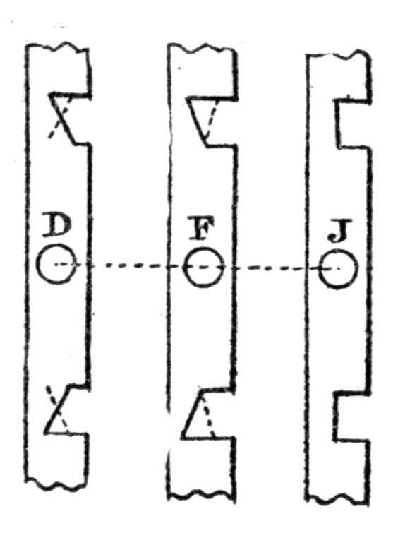
Fig. 271.
It is unnecessary to observe that if the edge of the rim be graduated, and the rules terminated by any convenient arrangement for arresting their motion at the graduations, the hours can be traced on a dial from which all marks have been erased. It then only remains to paint them in with ink.
622. Inks for Painting the Hours. Work up some clean lampblack in oil of spike lavender. Then add a small quantity of spirit varnish, and thoroughly mix the whole. This is applied with a fine brush, and the success of the operation depends very much on the selection of this latter.
623. Another Recipe. Mix together ivory black, pure wax, and turpentine; the more the turpentine is in excess, the more will the ink be colored. It is best adapted for filling in the figures engraved in dials, and a gentle heat should be applied to impart a smooth surface. Any irregularities in the painting may be erased by the aid of oil of spike lavender and soft bread.
HANDS.
624. To Set a Watch-Hand in Position. The most delicate part of this operation is the enlarging of the center hole of a minute hand and the closing of the hour hand socket when necessary.
Set the hand in cement on a brass plate that has a hole passing through at the point corresponding to the socket. The hole must then be enlarged with a semi-cylindrical drill to a diameter such that it will only be necessary to gently pass the broach through afterwards. The drill must not be worked too rapidly, and the plate may require to be immersed occasionally in water, so as to avoid heating the cement and thus loosening the hand.
When the hole in a watch-hand is too large, it may generally be sufficiently reduced by means of the staking tool.
625. To Redden Watch-Hands. Make into a paste (while holding over a lamp) a mixture of two parts carmine, two parts chloride of silver, and one part Japan varnish. Having spread some of this over the hands, lay them face upwards on a sheet of copper, applying heat until the desired tint is produced.
GLASSES.
626. To Drill Glass. A hole can be rapidly made in a piece of glass by using a steel spindle ground at the extremity to a point with three or four faces, and hardened in mercury. This spindle may be chucked in the lathe, or rotated between the finger and thumb, the point being moistened from time to time with turpentine or the mixture mentioned in article 594. The glass operated upon should be held against the blade with the thumb or a pad immediately behind it, and should receive a gentle rocking motion so as to prevent the drill from choking in the hole formed; and as soon as the point appears on the other side, the drilling should be re-commenced from that side. It is a good precaution to mark the point at which the hole is required with a diamond or the steel point before commencing, and the pressure applied while drilling must be but slight.
627. To Cut Glass. It is possible to cut a sheet of glass roughly to any required shape with an ordinary pair of scissors, if the operation is performed under water. Of course a smooth edge cannot be obtained by such means, but it will often be found sufficient.
A more exact method is to use a piece of ignited charcoal or the pastile mentioned below, first making a scratch as a starting-point and holding the heated substance a little in advance of the crack: this will follow the direction in which the hot body is moved. The method is available for dividing glass tubes or other objects in irregular shape.
What is known as the “Berzelius pastile” for cutting glass is formed of the following mixture: Gum arabic, 6 parts; gum tragacanth, 2³⁄₁₀ parts; benzoin, 2³⁄₁₀ parts; lampblack, 18 parts; and the requisite quantity of water. Mix the gum tragacanth with water and leave it to swell up for some hours; dissolve the gum arabic in a sufficiency of water, and powder the benzoin finely. Mix the three, forming a paste of such a consistency as to be moulded, the lampblack and a little water being also added. The pastiles are then formed by rolling between two plates.
The diameter of a watch-glass can be reduced by centering it in a lathe, chucking it between two pieces of cork or a pair of cork arbors, and applying a moistened piece of glass to the edge, or an emery stick. When the desired diameter is attained, polish the edge with pumice-stone followed by putty powder applied on a wet cork.
BROACHING.
628. To Broach a Hole Vertically. A hole in a plate, as for example, that in a barrel, is seldom maintained at right angles to the surface by young watchmakers when they have occasion to employ a broach. By adopting the following very simple method, success may be assured:
Take along cork of a diameter rather less than that of the barrel or other object operated upon, and make a hole in the length of the cork through which the broach can be passed. When the cork has been turned quite true on its end and edge, the broach is pushed through and used to enlarge the hole; by pressing against the back of the cork it is kept always against the barrel, and the vertically of the broach is thus maintained.
629. To Broach and Maintain the Hole Round. Many workmen either use bad broaches or work them in a jerky manner so as to make striæ within the hole. To avoid such distortion when uncertain of the hand, draw the broach somewhat out of the hole and insert in the space thus left one or two pieces of hard wood, forming a kind of jacket, so that at least two cutting edges of the broach may be prevented from acting; the broach forcing its way into the pieces of wood, will carry them round with it. A few trials will enable a workman to employ this method.
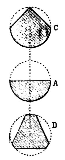
Fig. 272.
When operating on holes that are rather large it is a good practice to use broaches that are semi-cylindrical or triangular, their sections being as shown at C, A, or D, Fig. 272. C and D are excellent for smoothing a hole, but remove very little metal; A does more work in a given time and, if well handled, will maintain the hole very round. When operating on a large hole, these broaches can be rotated in a brace; but, in the case of small or medium size holes, it is much better to mount them in a drilling headstock like those used by case-makers for the joint holes, and the tools can be revolved by the aid of a hand or foot-wheel. Only one precaution need be noted, namely, the necessity of avoiding the application of too much pressure, so that the broach jams in the hole.
SOLID AND HOLLOW SQUARES.
630. To File an Arbor or Drift Square by Hand. The most expeditious mode of making a square, as, for example, that of a barrel-arbor, is by using the tool described in article 513, or one of analogous construction; but in their absence the square must be made by hand.
Soften the jaws of a hand-vise and make four flat faces on them, forming an exact square, either by filing or by attaching pieces by rivets. Having clamped the steel on which a square is to be formed in the vise, hold this in one hand and rest it in a recess in a wood block; with the other hand hold the file, determining its position by laying it on the upper face of the square before applying it to the arbor. After giving one or two strokes, test the truth of the face formed by again laying the file on the upper face of the vise. Then turn the vise through a quarter of a circle and proceed in the same manner; and so on for the other two faces. Before finishing the square and while there still remains a slight excess of metal on each face, ascertain, by examining the end and measuring the lengths of the faces, whether the square is accurately formed.
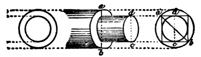
Fig. 273.
Put in the lathe and draw with flat file in the direction of the axis along each face. If the square is to be polished after hardening, proceed in the same manner, using an iron polisher in place of the file, to which longitudinal, transverse, and circular movements may be given.
After hardening, the square may be tempered to some shade between pale yellow and a deep blue, according to the purpose for which it is intended.
631. Another Method. Let it be required to fit a square to the hole in a keyless winding pinion, the diagonal of which is a′ b′, Fig. 273. Turn the end c d of the rod down until it exactly enters the square hole. Measure with a tapered strip of brass whose edges are filed sharp the diagonal a′ b′; this will give the diameter a b of the larger portion of the rod, as will be gathered from the figure a′ d b′ c.
Turn down the portions of the rod on which the square is to be made and file four faces, each time arresting the action of the file when it is on a level with the smaller cylindrical portion, maintaining the angles equal by observing that the four portions of the circumference retain their equality while gradually diminishing. By a little care and using the square-headed hand-vise described above, success may be assured.
632. To Drift a Square Hole in Steel of Moderate Thickness. The steel in which it is required to make a square hole must be very soft and thoroughly annealed, otherwise it is sure to crack under the action of the drift or when hammered.
To make the hole in the center of a stop-finger, for example, the hole must first be drilled of a diameter less than the side of the final square: the drift is then inserted, liberally supplied with oil. On removing the drift, the square is enlarged by means of a fine square file acting on each of its corners; then with slightly larger drifts the hole is gradually increased to the required size. They are driven with a rather heavy hammer, care being taken to maintain them vertical and with each change of drift a file should be passed over the surface to remove the metal that collects at the corners.
633. To Drift a Stem Winding Pinion. For this purpose the methods explained above are insufficient, on account of the great thickness of metal, which we repeat, must always be very soft.
Nevertheless, by using drifts that are very slightly conical, short, and roughed like a file in an inclined direction, and by using a number that succeed one another of gradually increasing diameter, steel of considerable thickness can be treated in the above manner; but it is far less expeditious than the method explained below.
The piece of steel with a hole drilled through it should be from a third to half as large again in diameter as it is finally required to be. After turning the surface true and the two ends flat, the tube is driven on to a long drift of suitable temper, well oiled and of nearly the diameter of the hole to be made. Clamping this drift in a hand-vise or sliding tongs, rest the steel tube on an anvil with its axis and one face of the drift parallel to the surface, and forge the tube with a medium size hammer. Turn the drift through a quarter of a circle, again forge the tube, and so on. Care should be taken that the drift is forced further into the tube from time to time, oil being at the same time applied.
A punching machine is also very serviceable for the purpose of drifting. Sometimes the attempt is made to forge the metal red-hot, but this is much more difficult on account of the rapidity that is needed in threading the hot steel, hammering and removing it. Moreover, the steel has to be heated several times and is apt to be burnt.
If the method above explained, in which the metal is kept cold, is carefully performed, it succeeds very well, but it must be observed that steel is often met with that is irregular in composition and cracks.
TO STRAIGHTEN A ROD, PLATE OR WHEEL.
634. A Steel Rod. When the rod is short use a large pair of sliding tongs or a hand-vise, the jaws of which have been softened in order to make a groove in each parallel to their edge. Placing the rod in the cylindrical recess thus formed between the jaws, fix one side of the hand-vise in a bench vise, holding a spirit lamp near the jaws and, as the steel changes its color, tighten the slide or screw of the former. When the metal assumes a blue color and the jaws are as tight as possible, remove the lamp, allowing the whole to cool slowly or by applying water.
The jaws should be formed so as to bend the rod rather more than is ultimately required, because steel on being released is apt to partially recover its initial curvature.
When the rod is long grip its two ends in the frame of a fret-saw, which should be somewhat strong. Then hold a lamp under the rod, at the same time stretching the rod more and more, and allow the steel to remain stretched until quite cold. If it has been sufficiently stretched the metal will be rendered perfectly straight.
635. A Plate, Escape-Wheel or Stem Wind Wheel. In the middle of a square plate that is moderately thick, fit a strong screw with a large and long head; this screw must pass freely through a disc that is perfectly flat and fits easily into the upper side of the escape-wheel. Now fix the plate between the jaws of a bench-vise, and, placing the wheel between this plate and the disc with a moderate pressure applied by the screw, hold a lamp to the under side, gradually tightening the screw as the steel changes color so as to obtain a maximum pressure when a blue temper is reached. Leave the whole to cool in position.
636. A Verge, Small Arbor or Pinion Staff. When steel is sufficiently tempered, it may be laid flat on a smooth piece of copper held in the vise and flattened by hammering as in the case of an ordinary rod; but if it is hard the blade of the hammer must be used. Every watchmaker knows, for example, that a verge is straightened by striking with the blade against its concave side, while the convex side rests flat on a smooth anvil. By the action of the hammer the side that is struck becomes a little longer, thus straightening the staff, It is not usually necessary to remove the marks left by the hammer, but if this has to be done the operation should be continued beyond what is necessary to straighten the metal, then temper it to a blue color and allow it to cool.
A small smooth taper arbor or pinion staff, can be straightened by resting it on a wood block, and rubbing the concave side lengthwise with a worn file of medium cut, applying considerable pressure, the arbor being firmly supported below to avoid breakage. The result is the same as with the blows of a hammer, but the marks left are barely visible.
FOOTNOTES:
CLOCK HAIRSPRINGS.
Repairers’ Assortment. Best Quality, Colletted, carefully arranged, box containing 50, fifteen kinds, by mail, $1.50
Same Assortment, box containing 100, 2.50
One Dozen for any make of clocks, .50
One-Half Dozen for any make of clocks, .30
Single Springs, .10
If your jobber doesn’t keep them send and get them direct, postpaid.
F. N. MANROSS, Manufacturer of every description of Clock and Gauge Hairsprings. FORESTVILLE, CONN.
The American Jeweler CHICAGO, ILL.


A Monthly Journal for Watchmakers and Jewelers.
As an advertising medium it is unsurpassed. Advertising Rates mailed on application. Has more paid subscribers than any other journal in the trade.
If in search of a situation or if you want a watchmaker, place your want ad. in The American Jeweler.
$1.00 per Year. Send for Sample Copy.
GEO. K. HAZLITT & CO. ...PUBLISHERS... 91 Plymouth Place, CHICAGO, ILL.
Patented May 25, 1886.
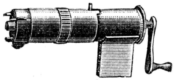
Eureka Mainspring Winder, FOR WATCHMAKERS’ USE.
This instrument is always ready for use, and will instantly wind any watch spring into coils to fit any American or Swiss Barrel. It is simple and durable.
Price, Nickel Plated, $1.25.
The trade will find it to their advantage to send us their orders, as we have the most experienced men, and all orders are filled with the best quality goods, the same day as order is received, and at the lowest market prices.
GREEN BROS. Importers and Jobbers of Watchmakers, Jewelers and Engravers Fine Grade Tools, Materials and General Supplies.
11 Maiden Lane, NEW YORK.
THE HARTUNG COMPANY, 211 STATE ST., CHICAGO. Watchmakers and Jewelers FOR THE TRADE EXCLUSIVELY. Fine Watch Repairing of all kinds our Specialty.
Demagnetizing. Changing key wind watches to stem wind. Watch case and jewelry repairing.
All work promptly and carefully executed. Our reputation is of a good and long standing. We will be pleased to send price list and information on demand.
CRUCIBLE FURNACE For Manufacturing
Jewelers....
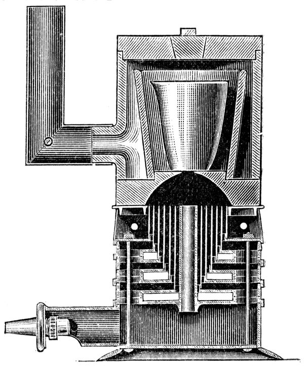
No. 15. Patented May 18, 1880.
No. 15. Crucible Furnace. This will take crucibles up to 4×3½ inches, holding about six pounds when full, and with ½ inch gas pipe, and a pressure of gas supplying about 50 feet per hour, will melt a crucible of gold, silver or brass in about 30 minutes, and the same quantity of cast iron in about 60 minutes from the time the gas is first lighted. It is made in a very substantial manner, and is recommended as a first-rate furnace for manufacturing jewelers, reducing photo waste, etc. The lid can be lifted away by a handle provided for the purpose.
Prices on Application. MANUFACTURED ONLY BY BUFFALO DENTAL MFG. CO
587-589 Main Street,
BUFFALO, N. Y.
Watchmaking

If you want to become a thorough practical watchmaker, you can do so at less expense and in less time at this school than any other place. Students received at any time. Send for catalogue and samples of engraving. Address:
Hutchinson’s Practical School for Watchmakers,
J. L. Hutchinson, La Porte, Ind.
SUPERINTENDENT.
Anything and Everything in the shape of Dials Made to Order from our own Design or from Yours.
Dials with Portraits, Monograms, Landscapes, Yachting, Hunting, Fishing, Polo, Base Ball, Tennis, Cricket, or in fact any design.
SOCIETY DESIGNS A SPECIALTY.
Complete Stock of Plain and Fancy Dials always on hand.
L H. KELLER & CO. Watchmakers and Jewelers Tools & and & Materials OF EVERY DESCRIPTION.
64 Nassau Street NEW YORK.
The Chicago Watchmakers’ Institute
A Modern Trade School. Best in America. Scientific and Practical In all its Methods.
TEACHES Watchmaking and Repairing,
Jewelry Work and Engraving,
and gives a Thorough Course in Optics.
Call and see our school and its work, or send for catalogue. GEO. D. PARSONS, Principal.
913 D, Masonic Temple,
CHICAGO, ILL.
WHEN YOU NEED THE BEST
Pivot Polishers, Crown Chucks, Staking Tools, Gear Cutters, Turning Tools, Pivot Drills, Idler Pulleys, Roller Removers, Pump Drills, Hairspring Stud Index, Tempering Compound,

Or any of the tools you need daily; and when you want the best and most practical tools, those that have been designed by practical workmen and proved by them; when you want the latest, best and cheapest tools; send for circulars and prices to
A. W. JOHANSON, Manufacturer of Watchmakers’ and Jewelers’ Tools,
326 Wells Street
CHICAGO, ILL.
PRACTICAL BOOKS
....FOR....
Watchmakers AND Jewelers.
FOR SALE BY
GEO. K. HAZLITT & Co.,
91 PLYMOUTH PLACE,
CHICAGO.
Staff Making and Pivoting. Practical directions for making new staffs from raw material. By Eugene E. Hall. Chapter I. The raw material; the gravers; the roughing out; the hardening and tempering. Chapter II. Kinds of pivots; their shape; capillarity; the requirements of a good pivot. Chapter III. The proper measurements and how obtained. Chapter IV. The gauging of holes; the side shake; the position of the graver. Chapter V. The grinding and polishing; the reversal of the work; the wax chuck. Chapter VI. Another wax chuck; the centering of the work. Chapter VII. The finishing of the staff; pivoting; making pivot drills: hardening drills; the drilling and fitting of new pivots. Illustrated with 24 engravings. 48 pages.
Paper covers $ 25
Watch Repairing. By N. B. Sherwood. Contents: The Bench and its Accessories; The Vise and Oilstone; Lathe Appliances; The Jacot Lathe; Depthing Tool; Expanding the Web of a Wheel; The Spreading Tool and its Use; The Rounding-Up Tool; Stud Remover; Opening the Regulator; Roller Remover; Replacing Broken Teeth; Graining Polishing Blocks; Polishing Steel Work; Polishing Pivots; Superiority of Conical Pivots; The Cutting Engine; To Cut ’Scape Wheels; Replacing Broken Arbors: Hardening and Tempering. Illustrated.
Price 35
The Watchmakers’ and Jewelers’ Practical Hand Book. A guide to the student and a workshop companion for the practical watchmaker. Hundreds of valuable suggestions from private formulas and the best authorities, together with hints on making certain repairs. An invaluable book for the workman. The most valuable book for the money ever offered to the trade. Fifth Edition, Revised and Enlarged. Edited and compiled by Henry G. Abbott. Illustrated with 154 zinc etchings. 118 Pages. Flexible muslin, 50 cents. Paper covers
35
Prize Essay on the Detached Lever Escapement for watches and timepieces. A practical and theoretical treatise, by Moritz Grossman, to which the first prize was awarded by adjudicators appointed by the British Horological Institute, London. 118 pages, bound in paper covers, with 20 full page plates, bound in a separate volume. Two volumes, price,
1 50
Acme Record of Watches Bought and Sold. A complete record for dealers in watches, by which they can at all times tell what watches have been sold, by whom bought, price paid, profit made, etc., and in case of the watch being imperfect, the dealer can readily ascertain from whom he purchased it, or if stolen he has a full description of them which should materially aid in their recovery. Books of 3,000 Entries, substantially bound
$1 00
The Acme Record of Watch Repairs. A simple and economical method of recording watch repairs. Book of 1,000 entries, substantially bound
1 00
The Acme Record of Jewelry Repairs. A simple and economical method of recording jewelry and miscellaneous repairs. Book of 1,000 entries, substantially bound
1 00
The Acme Watch Guarantee Book. If you desire to increase your watch repair business, purchase an Acme Guarantee Book, and advertise the fact that you “give a written guarantee with all work turned out.” These books are printed with a stub so that you may keep a record of all guarantees made, with date, name of owner, description of movement and case, repairs, etc. They are bound in heavy, substantial covers printed on good paper and perforated all around so they can be easily torn out.
Books of 200 Guarantees 1 00 Books of 300 Guarantees 1 50 Books of 500 Guarantees 2 52
Abbott’s Americas Watchmaker and Jeweler. By Henry G. Abbott. An Encyclopedia for the Horologist, Jeweler, Gold and Silversmith. Containing Hundreds of Private Receipts and Formulas, Compiled from the Most Reliable Sources. Complete Directions for Using all the Latest Tools, Attachments and Devices for Watchmakers and Jewelers.
Among other things contained in this volume may be mentioned a thorough explanation of adjustments, both to positions and isochronism; directions for making all the alloys used by a watchmaker, jeweler and metalworker; a review of all the escapements, their action, construction and proportion, together with diagrams of each escapement; an exhaustive treatise on balances, their expansion and contraction, auxiliaries, sizes and weights and direction for poising; the balance staff, and full and complete directions for making and replacing new staffs, together with the use of the graver in turning and the manipulation of measuring instruments; directions for making twenty different cements of great value to the watchmaker and jeweler, including lathe wax; directions for cleansing, pickling and polishing all kinds of metals: magnetism and the use of the various demagnetizers; electroplating, bronzing and staining all metals; gauges of all kinds, and directions for using; soldering and directions for making all kinds of hard and soft solder and fluxes; steel, its treatment in annealing, hardening, tempering, etc.; watch cleaning, repairing, etc.: a treatise on wheels and pinions: directions for using all modern tools and appliances; and hundreds of miscellaneous receipts, formulas and hints on all kinds of work, of great value to every workman. This edition contains forty-four pages more than former editions, and each page contains one-third more matter than the pages of former editions. An alphabetical list of over five hundred European watchmakers who manufactured watches prior to 1800, with years in which they carried on business, from which the watchmaker can easily establish the age of any movement that a customer may desire to know about; an alphabetical list of all books on horology published in the English or French language prior to 1850; portraits and sketches of all the celebrated watchmakers of the world from 1600 to 1894. 354 pages. Illustrated with 288 engravings. Paper covers, $1 25. Fine muslin
$1 50
A Simple and Mechanically Perfect Watch. By Moritz Grossmann. A Prize Essay on the Construction of a Simple yet Perfect Watch. Written in a masterly manner by one of the greatest of Horological Authors. Illustrated with many engravings. From the standpoint of the practical man at the bench this is one of the most exhaustive essays ever written on the subject and no practical workman can fail to appreciate it. 96 pages 38 diagrams. Paper, 75c. Fine muslin
1 00
The Watchmakers’ Library. This book consists of a collection of the best articles from the various trade journals of this country and Europe, among the authors being Moritz Grossmann, M. Kessels, Chas. Spiro, Chas. Reiss, Herman Horrman, P. M. Youlen, M. Sandoz, Herman Grosch, James U. Poole, E. Sordet and Vincent Lauer. The papers are all of a practical nature and of great value to the practical watchmaker, the whole forming a volume of 290 pages and index. In Paper Covers
1 00
Prize Essay on the Balance Spring and its Technical Adjustments (Baroness Burdett Coutt’s Prize). By M. Immisch. A description of the invention of the balance spring, its effect upon the art of watchmaking; the effects of inertia of the balance; resistance of the air; balance adjustment by means of turning screws and washers; proportions of spring and balance; nature of spirals; lengths of balance vibrations and their effect upon the timing; pinning in equal and unequal coils; the Breguet spring; making its curves, pinning; regulating isochronal springs, etc. Fully illustrated with numerous engravings and diagrams. Cloth. Price
1 00
Repairing Repeating Watches. By C. T. Etchells. A practical treatise on the subject and the only one in print. Fully illustrated. The most vexatious repairs that come to the watchmaker are those on repeating watches—and yet they are the most profitable if you know just how to make them. Not every watchmaker can make them, and that is just why they are profitable. Do you know how? If not, why not? You are never too old to learn. Paper covers
35
The Escapements. Their Action, Construction and Proportion. All watch and clock escapements thoroughly illustrated and described Illustrated with twenty diagrams. Paper Covers Price
$ 50 Same in cloth binding 75
Prize Essay on Watch Cleaning and Repairing. By F. C. Ries. This work took the first prize, (offered by The American Jeweler) in competition with thirty-six other writers. Contents: Examination of the Movement; Taking Down; Fitting the Dial; Fitting Center Pivot and Bridge; Bushing; Endshake; Worn Center Pinions; Truing the Barrel; Repairing the Ratchet; Putting on Square on a Fusee; Examination of Mainspring; Stemwind Mechanism; Examination of Train; Imitation Gilding; Pivots; Making Balance Staff; The Hairspring; Jeweling; Cleaning in General. Price
25
Watch and Chronometer Jeweling. By N. B. Sherwood. A complete treatise on this subject and the only one in print. Contents: Peculiarities of Gems used in Making Jewels; Requisite Tools and How to Use Them; Shaping and Polishing the Jewel; Opening the Jewel; Setting the Jewel; The Endshake Tool; General Hints to the Repairer. Illustrated. Price
35
General Letter Engraving. By G. F. Whelpley, the acknowledged authority on engraving. His latest and best work. Contents: General Hints to Beginners; Lines and Curves; Originality; Practice Material; Position of Graver; Treatment of Gravers; Correct Spacing; Coffin Plate Engraving; Necessary Tools; Laying out the Work Preparation of Plate; Use of Gravers; Methods of Cutting; Slope and Height of Letters; Inclination of Graver; Transfering; Letters Appropriate for Long and Short Names; Harmony in Laying Out; Touching Up; Difficult Materials and their Treatment; Tools and Materials; Sharpening Gravers; Choice of Tools; Engraving in Rings; Gravers for Same: Engraving Blocks and Stands: Ciphers, their Formation and Ornamentation; Inscriptions; Best Manner of Cutting; Ciphers as Compared with Monograms; Monograms and their Treatment; Figure Monograms or Cipheroids; Intertwining, Complex Monograms; General Treatment. Copiously Illustrated. 112 pp. Paper $1.00. Cloth
1 25
The Watchmakers’ and Jewelers’ Practical Receipt Book. A workshop companion, comprising full and practical formula and directions for solders and soldering, cleaning, pickling, polishing, bronzing, coloring, staining, cementing, etching, lacquering, varnishing, general directions for finishing all metals, hundreds of miscellaneous receipts and processes of great value to all practical watchmakers and jewelers. This is the only book on the market to-day that gives full and complete directions for etching names, portraits, etc., in the bowls of souvenir spoons and silver articles in general. This so-called trade secret is sold by certain persons at $5.00. Dozens of other “trade secrets” that are advertised for sale in trade papers at from $1.00 to $5.00 can be found in this book. Worth its weight in gold to any practical watchmaker and jeweler. 132 pages, illustrated. Paper covers, $1.00. Fine English muslin binding
1 25
Poising the Balance. An Essay of unusual merit. By J. L. Finn 25
Hairspringing. A complete treatise on the art of hairspringing. By A. Z. Price
25
Adjustments to Positions, Isochronism and Compensation. The only work on the subject in print. 50 pp. Illustrated. Price
25
Repairing Watch-Cases. A practical treatise on the subject. By W. Schwanatus. Contents: Repairing the Pendant; Lining Pendant Holes; Work at the Joints; Soldering the Bezel; The Closing of the Case; Taking Out the Dents. 40 pp. Price.
25
Jewelers’ Practical Receipt Book. Contains a mass of most valuable receipts, formulas and information, gathered from the best and most reliable sources. Fifth edition, revised and enlarged. 48 pp. Price
15
Prize Essay on the Balance Staff and Cylinder. By P. W. Eigner. This essay took the first prize offered by the American Horological Society. Gives methods for turning, grinding and polishing, from staff to pivots. Illustrated with numerous engravings. Paper covers
25
Compensating Pendulums and How to Make Them. A practical treatise on the construction of mechanically perfect Pendulums, for the use of watchmakers. By J. L. Finn and S. Riefler. Illustrated. Paper covers, Price
35