PART IV. TOOLS AND APPLIANCES. (continued 3)
Reading edition
Center the plate by the point o from which the arc a b is struck; now bring the cutter to such a position that its outer cutting edge coincides with the arc a b, and bring it against the plate; set the face-plate in motion, not, however, by using the treadle, but by the hand at its circumference, and traverse the arc from b to a; then withdraw the cutter. By this means the projecting angles, left white in the figure, will be removed, and a clean edge will be left to the groove.
As an operation of this description will not present any difficulty, further explanation appears unnecessary; for the information above given will enable any watchmaker to make curved grooves of the kind indicated.
If it is required to smooth the surface of the groove, replace the cutter by a pegwood stick that can be rotated with friction, and the end of which just fits into the groove, charging it with pumice or other stone and oil. One hand moves the face-plate backwards and forwards, while the other rotates the stick.
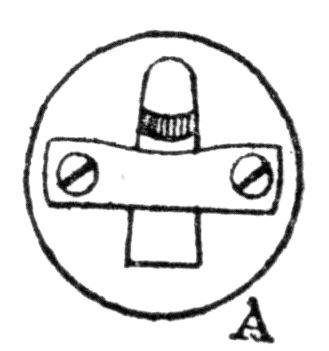
Fig. 170.
365. To Cut the Cylinder Escape-Wheel Cock Passage. As a rule the cock is cemented, inverted, to a wax chuck, and the passage cut or enlarged on the lathe. It is more expeditious to use a plate provided with a clamping bridge, as shown at Fig. 170. The face-plate should be made to oscillate backwards and forwards by hand, and not rotated by the wheel.
366. To Make a Straight Groove. First method. The tool devised by M. Chopard, director of the school of horology at Besançon, and shown in Fig. 171, is used for this purpose. As will be seen, it consists of a small lathe which is adapted to the slide-rest as follows:
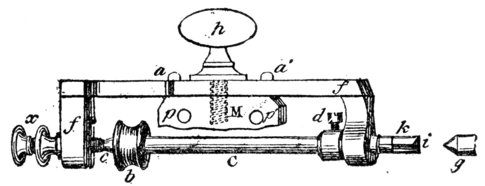
Fig. 171.
Two pins, a a′, are planted in the top of the tool-holder, the cutter together with the plate by which it is clamped having been first removed. Holes drilled in the frame f f fit accurately onto these pins, while a screw, h, passing through an intermediate hole, affords a means of firmly fixing the apparatus to the tool-holder M.
This tool should satisfy the following conditions: The arbor C should fit into a recess that receives a cutter, but without coming into contact with it; this arbor should be parallel to the bed of the lathe; and, lastly, the axis of C should be on a line with the lathe center.
367. Having set this little appliance in position, trace on the watch-plate two lines indicating the directions of the sides of the groove as well as lines fixing its length. Now place the plate in the dogs, setting the point of the pump-center anywhere on the line drawn along the middle of the groove. Turn the plate so that this line is horizontal, and fix it in any way that is convenient.
The arbor C carries a revolving cutter k, which can be changed as desired, and is held in position by the clamping screw d. Assume that the diameter of this cutter corresponds exactly with that of the required groove; advance it towards the plate, turning the wheel rapidly, the cord being round the ferrule b; a circular sink will thus be formed in the plate of the same diameter as k.
When this has been cut to a sufficient depth, the tool is moved parallel to the face-plate, and the cutter k, continuing its movement of rotation, will now cut, not with its extremity i, but with its sides. It will thus form a straight groove of any desired length.
368. The cutter is a three-sided prism, or it may have four sides with four cutting edges on the sides, and only one cutting edge at the extremity i. If it is preferred to retain only the two acting edges that start from either end of the cutting edge i, they may be made more acute, and the other pair reduced by means of a file.
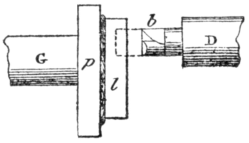
Fig. 172.
369. Second method. This is simpler than the one just considered. At the end of a rod G, Fig. 172, which takes the place of the cutter in the slide-rest, a plate p is fixed. A line is drawn across the face of this plate in such a position that, when G is clamped in the tool-holder, this line is horizontal, and in the plane that contains the axis of the pump-center.
Let it be required to cut a straight groove in the piece of brass l. Wax it to the plate p so that the axis of the required groove is over the line traced on the plate. Now fix G in the tool-holder and replace the pump-center by a rod D, the extremity of which is formed into a cutter of a diameter equal to the width of the required groove; the rod D should be fixed in the hollow arbor by a screw. It is then only necessary to set the cutter in motion, forcing the piece l against the revolving cutter, until the requisite depth is attained. Then, by making the tool-holder travel parallel to the face-plate, the groove will be elongated until of the desired length.
370. The cutter may be of the form shown in Fig. 171, or it may be as shown at b in Fig. 172, since the movement is always in the same direction. The cutting edges are each formed by two small inclined faces, one pair of which is shown at b; they occupy half the diameter of the cutter. At the back of this pair the cutter presents the appearance of the lower half shown in the figure and vice versa.
It will be evident that the two sides of this cutter will act while its motion is continuous in one direction.
Besides the numerous operations that can be performed on the lathe as we have hitherto indicated, it may be employed, if divided on the head stock, for tracing out angles, marking the crossings of a wheel, a balance, etc., and for other purposes, many of which are referred to in the course of this work.
PRODUCTION OF SCREW THREADS. SCREW PLATES AND TAPS.
371. The lathes employed in the manufacture of screws are of two kinds; those intended for polishing and, where necessary, modifying the form of screw-heads, much used by watch examiners and repairers, and those specially designed for cutting the threads, which are mainly in use in factories.
Before discussing them, however, we will give some account of the screw-plates and taps in ordinary use.
372. Common Hand Screw-plates. The use of these is much facilitated by providing a second plate perforated with holes of such sizes that a spindle which just passes into a hole of any given number will be of the size most convenient for forming a screw in the hole of the same number in the screw-plate. For a long time we have made use of two Latard screw-plates so made that a rod which would enter one hole without play was of the most convenient size for forming a screw in the next smaller hole but one (thus the plate perforated with plain holes can be replaced by a second screw-plate, or by using the successively larger holes on a single plate as gauges).
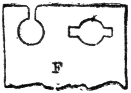
Fig. 173.
In order to form a screw that is clean-cut and even, with the least possible straining of the metal, the holes in the screw-plate should have notches cut as shown at F, Fig. 173; they should be carefully hardened and well polished on each side of the notch, and this system is now even applied in the case of the smallest jewel screws.
373. Screw Dies. The ordinary plate, in which notches are not cut at the sides, squeezes up and strains the metal. This effect is less marked when separate dies are used, and disappears entirely if only a small quantity of metal is removed at a time, and the cutting edges of the dies are smooth and in good order. In addition to possessing other advantages, this form of screw-plate enables us to obtain at will screws of the same thread and different diameters or of the same diameter and different threads. The dies must be carefully fitted to the slides that receive them. Dies cannot be employed for cutting very small screws.
374. Fine-threaded Screw-plates. At the present day these can always be obtained at the material stores; but thirty years ago it was not so, and the watchmaker was obliged to make them for himself. The following method was adopted:
Take a screw formed with an ordinary plate, in which the thread is broad as compared with the hollow. If the screw does not satisfy this condition it must be modified thus:
Having ascertained that it runs true, and that it is larger than will be ultimately required, insert it in a chuck in your lathe. The T-rest must carry a smooth horizontal rod of hardened steel.
Rotating the screw, hold a slitting file in the hollow; the file should fit into this hollow accurately, and should be smoothed on its two sides, only cutting with one edge. The bar of hardened steel will determine the depth to which the file is allowed to cut. By this means a screw is obtained that has a thread thick at the bottom. With the graver remove the top of this thread, round off its corners, and harden the screw, filing three facets along its entire length, that make it taper.
The tap, having been thus prepared, is employed for cutting a thread in a piece of steel, not too thick, that has been previously annealed, and in which a hole is drilled of the proper size. The thread of this internal screw will be thin and the hollow proportionately broad.
The plate is now hammered cold with care until the thickness is so far diminished that the thread and hollow are as nearly as possible of equal thickness. Harden it and chamfer the ends of the hole with a conical steel point and oilstone dust. Then clean it and cut a thread on a piece of soft steel which may be formed into a tap.
If the operation has been properly conducted, this tap will satisfy the prescribed conditions, and, when hardened, it is to be employed to cut a thread in a second steel plate, which will be employed as a screw-plate; for that first formed must, in consequence of the hammering to which it was subjected, present irregularities in the hole, and can only be used to cut one or two taps cautiously. It is useless for making screws or tapping brass. (See also 378.)
375. To Clear a Stopped Hole in a Screw-Plate. Drill a hole through the center of the piece of metal that fills up the hole, taking care to maintain it central, and to employ a drill that is sufficiently small to avoid all risk of contact with the screw threads. Pass a broach through this hole and, after tightening it with a few gentle blows with the hammer, turn it in such a direction that it tends to unscrew the broken screw, which will in nearly every case, be removed without difficulty by this means.
TAPS.
376. Screw-cutting comprises two distinct operations—the formation of a spiral thread on the circumference of a cylindrical spindle, and of a spiral groove within a cylindrical hole to receive this thread.
Taps are made either by means of a screw-plate or in the lathe; we shall presently refer to this second method. Every watchmaker may be supposed to have received, early in his career, instruction as to the cutting of a tap with a screw-plate. Great caution is necessary in the hardening, for if the tap is not true or the metal burnt it will cut badly and be apt to break. Taps are cleaned after hardening with a piece of wood in the lathe or between two hard pieces of pith covered with oilstone dust, and either three or four cutting facets may be made. It is important to avoid the production of a burr in making these facets; a good plan is to make them while the metal is still soft, and to pass the tap through the plate subsequently, as a sharp cutting edge is thereby produced. The facets should be carefully smoothed, and the use of coarse rouge is an advantage.
A tap with three facets gives the cleanest cut and leaves the most space to receive the metal that is removed, but with four facets the roundness of the hole is more certain to be maintained.
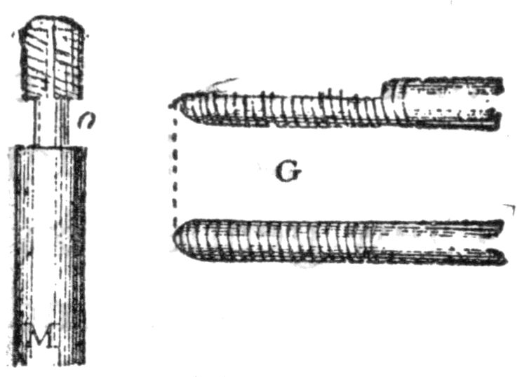
Fig. 174.
We have seen taps formed as represented at M, Fig. 174, so that the object in which a thread is being cut is loose at the part o, when the direction of movement of the tap is reversed. They are also at times made semi-cylindrical, as at G, and work well in the lathe for tapping brass, but we have not tried this form with steel.
377. To Cut a Tap when of Considerable Length. The following precautions must be observed in order to ensure that a long screw shall be both round and true.
The steel must be of very goad quality, and loose dies should be used in preference to a screw-plate. It is a good practice to employ two pairs of dies (or even more); one to rough out the screw, leaving the thread somewhat larger than it will finally be, and the other to finish after having trued it, and even sometimes lightly turned the surface in places. Very little metal must be removed at a time, the dies should have sharp cutting edges, and a rather large number of threads.
A screw can be made in the ordinary manner in a screw-plate rather larger than is required, then reduced to the requisite diameter, and finished with a plate in which the holes are of the form shown at F, Fig. 173, or in a screw-cutting lathe; in either case, however, care must be taken to avoid straining the metal in its passage through the first plate, on account of the tendency which it then possesses to become distorted in the hardening.
If a micrometer screw is required, that is, a screw of absolutely uniform pitch, it is necessary to apply to makers of astronomical and other similar instruments of precision.
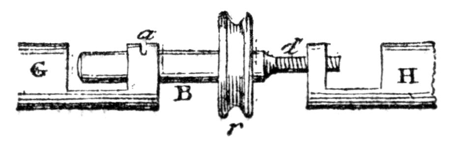
Fig. 175.
378. To Cut a Screw of any Desired Pitch and Diameter. Let it be required to cut a thread on the stem B, Fig. 175, of any pre-determined pitch that already exists in a screw-plate. Turn down the portion d to such a diameter that a screw can be cut on it in this hole, and fit two runners to the lathe of the form shown at G and H. The end of H is drilled and tapped so that d turns freely in it, and a hole is drilled in G to receive the stem B freely, but without sensible play, and a fine notch is cut at a.
It will be obvious that if now the ferrule r is caused to rotate, while a fine saw or file is inserted in the notch a, a screw will be formed on B of the same pitch as that on d, although there may at the same time be a very considerable difference in their diameters. This method may be adopted in place of that explained in article 374 for obtaining a fine-threaded screw.
379. Left-handed Screw Taps. The manner in which these are made in the screw-cutting lathe will be subsequently explained; in its absence the watchmaker may adopt one of the following methods:
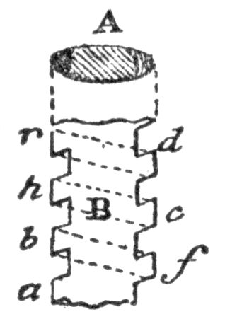
Fig. 176.
First method. If, when an internal screw has been cut with a right-handed tap, B, Fig. 176, it be required to tap a second hole in the reverse direction, the following plan may be resorted to:
File the original tap B on two opposite sides, so as to give it the flattened shape shown at A in the same figure. Insert the end into the hole to be tapped and turn the tap to the left with the application of considerable pressure, so as to force the tap to bite. When the tap has been passed in and withdrawn there will be found to be a left-handed thread cut in the hole. For, if the tap is turned towards the right, the thread f passes into the groove already formed by the thread a; but, if turned towards the left, f will originate a groove into which b will pass, traveling in an inverse direction to that previously given to it.
The finer the thread of the screw, the better is the chance of success, and with a wide thread it is often necessary to recommence two or three times. If a plate or pair of dies be cut in this manner and hardened, they will serve to cut an even left-handed tap.
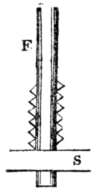
Fig. 177.
Second method. Attach a comb to one or two sides of a cylinder, as indicated at F, Fig. 177. This can be used to cut a thread in the piece of metal S, that is either right or left-handed according to the direction of rotation of F, sufficient pressure being at the same time applied to force it into the plate. The pitch of the thread will depend on the amount of pressure applied. This plan is only a modification of the one described above, and, as in that case, success can only be guaranteed when a means is adopted for securing a definite relative amount of motion in F around its axis and S vertically.
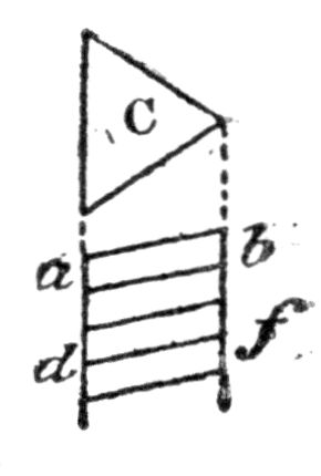
Fig. 178.
Third method. A tap of unhardened steel is filed into a triangular form, C, Fig. 178, and twisted so as to bring the angles b, f, towards a, d, etc.; we thus obtain a tap which will serve, throughout a certain portion of its length, to cut a left-handed thread, but the part that is not so adapted, at the extremities, will require to be removed before hardening.
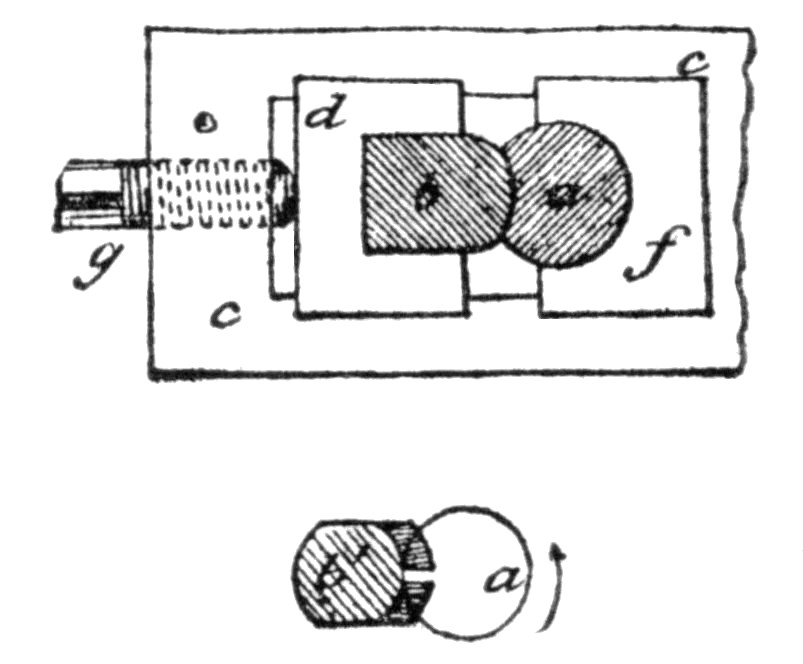
Fig. 179.
380. To Make a Left-handed Tap by Means of a Right-handed Tap. A portion of the right-handed tap is filed off on three faces to the section shown at b, Fig. 179, and firmly set in the die d so as to be held in the frame for screw-cutting dies. A second die, f made of brass and having a semi-cylindrical recess opposite b is fitted to the frame. The diameter of this semi-cylinder should be the same as that of the rod on which a left-handed thread is to be cut. Now grip this rod as shown at a by means of the screw g, so that it is held between the die f and the block b, and rotate the frame or the rod a towards the left; a spiral groove will thus be cut by the thread on b. It is sometimes an advantage to cut this thread lengthwise in the manner indicated at b′.
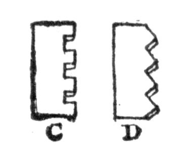
Fig. 180.
This method enables us to cut a given thread on a rod of any given diameter. From an examination of Figs. 179 and 180, it will be seen that a simple comb of the form of C or D, carefully made by hand and fixed in the place of b, can be employed to cut a right or left-handed thread on any given rod; it is advisable, however, that the teeth of the comb be inclined to the axis of the screw, like the thread of an ordinary tap, as otherwise the operation becomes more difficult and success less certain.
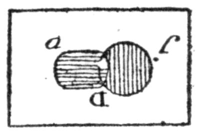
Fig. 181.
The method may be simplified by taking a brass plate, D, Fig. 181, of sufficient thickness, and firmly setting in it the right-handed tap, v, having only filed away two opposite faces before hardening. The rod to be tapped is then introduced with considerable pressure into the hole j, and, if rotated towards the left, it will receive a left-handed thread of the same pitch. The notch shown at b′, Fig. 179, will facilitate the operation, as a cutting action will take the place of compression.
381. M. Gontard has suggested a modification of this arrangement, which consists in forming the die f, Fig. 179, so that the original right-handed tap can be embedded in a hole previously tapped in it and filed away on the side towards b so as to expose a cutting edge; and he points out that, by suitably inclining the frame with reference to the axis of the rod to be tapped, the appliance can be used to cut a double or even a triple-threaded screw, right or left-handed. He further draws attention to the fact that in a screw formed in this manner the sides of the thread are smooth and polished, a condition which cannot be secured when either a plate or dies are used.
382. To Increase the Diameter of a Tap. It sometimes happens that a screw will not penetrate to a sufficient depth, or fits too tightly into its hole, owing to the tap employed being of a less diameter, either in consequence of the hardening, polishing or wear, or through having been formed in a different screw-plate. In such a case the following expedient may be resorted to:
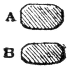
Fig. 182.
Make a fresh tap in soft steel and file away two opposite sides so as to give it the section shown at A or B, Fig. 182: after measuring the diameter at several points in its length, hammer gently on the flattened sides. With a little care and by using a micrometer at intervals for testing the alteration in diameter, it will be found that the required increase can be obtained without much difficulty. The tap is then hardened and polished, etc.; indeed, it is best to make a fresh tap.
METHODS OF TAPPING HOLES.
383. It is needless to refer to the method of tapping by hand, as it is well known to all practical men.
384. Tapping in the Lathe. The plate of a watch is gripped in the dogs of a face-plate, the hole to be tapped being centered by means of the pump-center, which is then withdrawn, and a tap held to the hole; the face-plate is then caused to rotate either by the hand resting on its circumference, a slight backward motion being given after each advance, or the motion may be continuous and be given by the wheel. In the latter case, however, the tap must have a good cutting edge and only be held in the hand with the degree of force required to make it cut, so that it may rotate without breaking in case the resistance opposed becomes too great. The tap may be steadied on the T-rest.
385. To Tap with a Mainspring Winder. The ordinary mainspring winder will, if the click work is removed, be found very convenient for tapping holes, and indeed, for forming the external thread on screws. Having removed the winding arbor, replace it by a tap carefully centered; then introduce its coned end into the hole in the plate, which must be pressed forward while the handle is turned, a short backward motion being given to it at frequent intervals. When the tap is engaged sufficiently in the hole it is merely necessary to maintain the plate at right angles without applying pressure.
386. To Tap with a Bow. Instead of the mainspring winder, one of the small drill-stocks to be driven by a bow, consisting of an arbor, with a coned hole at one end and ferrule at the other, supported in a frame that is clamped in the vise, may be used. They are to be obtained at any tool-shop.
The bow being on the ferrule and the tap properly centered in the arbor, the hole is held against the coned end and the bow worked with an alternate forward and backward movement; but if the tap has a good cutting edge and the bow is strong (of steel or cane), a hole may be tapped with a single stroke of the bow. After a few trials the method will be found very easy and certain.
A regular and rather slow motion should be given to the bow, which should be long and strong. It is well to ascertain the number of revolutions of the ferrule that correspond to a stroke of the bow, so as to ensure that the tap is not introduced to a greater depth than is required. If it is desired that the screw work easily in the hole, the tap should be moved several times backwards and forwards.
387. The little turns here referred to, some of which are perforated throughout their entire length and others only at one end, are very cheap and will often be found useful; they can be adapted to receive drills, broaches, taps, etc.
388. To Tap in an Ordinary Lathe. In factories it is a common practice to tap the holes in plates, etc., and even to cut the threads of screws in a lathe specially arranged for the purpose. The tools adapted for such work are of two kinds: in some the tap enters to the required depth, when it is immediately arrested, disconnected, and then rotated in an opposite direction; in others, the tap advances to a definite point, and is immediately withdrawn. As a rule, however, the tap remains stationary and the object is caused to rotate.
389. Beillard Lathe for Tapping Screws. The axis F M, Fig. 183, is perforated throughout its length. At F, the screw-plate G is dovetailed into it. The inner end of the hole in this plate is slightly coned to facilitate the insertion of the brass wire D, and it must be exactly in the axis of F M. A guide B sliding on two rods c, c, is traversed by the rod D which can be clamped in it by the screw a.
By pushing D against the screw-plate at the same time that the handle N is rotated, a thread will be traced on it and it will emerge at k. When B has advanced to the point m, the screw a is released, B is drawn back, and a again clamped.
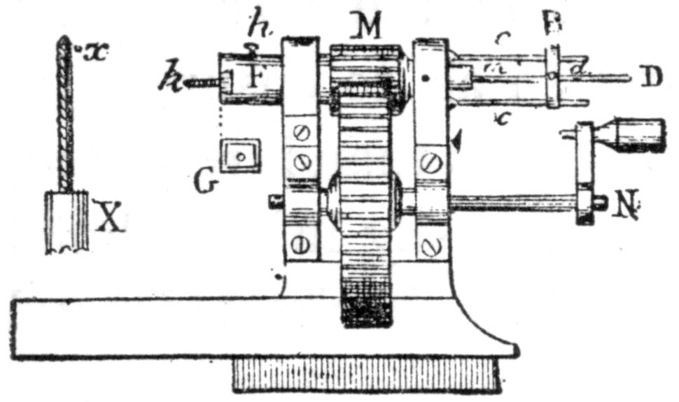
Fig. 183.
When a long screw, such as X x has to be tapped, the screw-plate is fixed at m, and the guide B is fastened on to the portion X. Of course the hole in the screw-plate must always be abundantly provided with oil.
If the screw-plate F is replaced by a plate perforated with a round or square hole, a drill, broach or tap may be substituted for k, being clamped by the screw h, and the tool is at once available for drilling, broaching or tapping any given hole.
RAPID MODE OF MAKING A SCREW.
390. The methods ordinarily adopted by watchmakers are too well known to need description; we will therefore at once proceed to give a special plan recommended by M. Vissiere.
An eccentric poppet-head with boring-plate, Fig. 185, is fitted to the bed of the lathe, the eccentricity being such that the axis of the centers is at the point a on the circumference of the circle a y. The conical hole, having a center at a, is cut away towards the rim of the plate to the degree indicated in the figure, and its center is so placed that the vertical line f and the radius d are inclined at 120°. The position of the T-rest is shown at s, and by bringing it into actual contact with the disc the steadiness of both is increased.
The fixed headstock of the lathe is provided with a runner of the form B, Fig. 184, terminating in a point m at one end and a hollow cone or funnel n at the other end.
Having filed the ends of a rod T, of any required diameter, square and fitted a ferrule, support it between the two cones, a of the boring-plate and n of the runner. Near the end a cut a hollow r sufficiently small to allow the stem to pass through the notch in the hole a, Fig. 185. After passing it through, the rod will be supported as shown at H, Fig. 184, so that the rim e i rests against the cone.
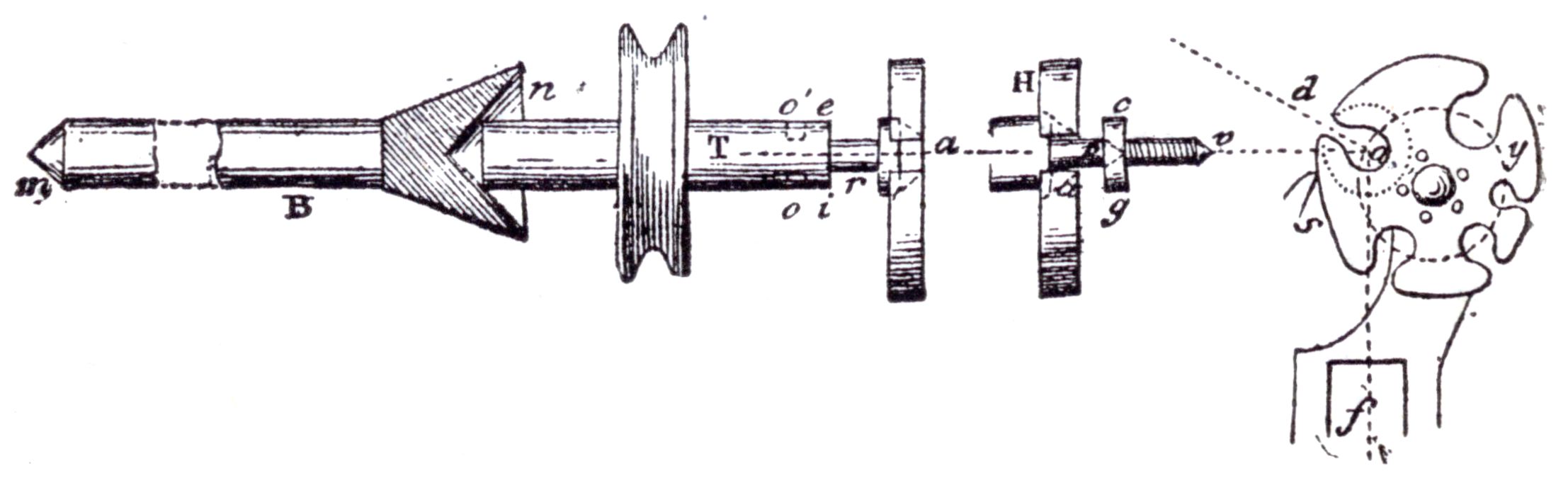
Fig. 184.
Fig. 185.
Further explanation is hardly necessary; after removing the portion c g with a graver, turn down to a point p. When making a screw, turn out a second hollow o o′; it then only remains to turn off the disc at the extremity, and the screw will be roughed out of the form c p g v.
If it is preferred to work with a point at the left-hand end of B, remove the rod after the point v has been turned, replace m B n by a common runner, reverse B, and recommence the operation.
It would be difficult to devise a method for roughing out a screw and making a point that would be more expeditious than the one here described.
SCREW-HEAD TOOLS.
391. These are of various kinds: some work by hand and others by a bow. The jaws are brought together sometimes by a sliding ring, and at others by a milled head placed between them and rigidly attached to a pin tapped with right and left-handed threads that engage in the jaws. But neither of these plans is good; the screws are not held firmly and they are rarely well centered; owing to the slight displacements of the jaws.
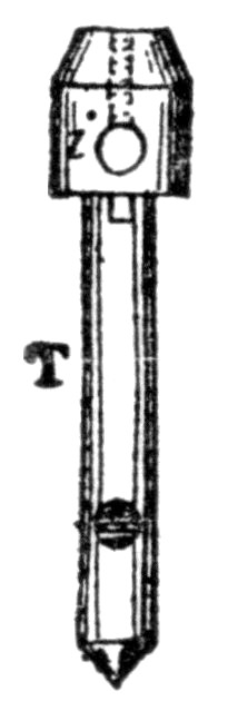
Fig. 186.
A better plan is to arrange, either in the lathe or in the jaws of the screw-head tool (when driven by a bow), a series of chucks of the form shown at T, Fig. 186. They are easily made and tapped, the hole i serving to remove the metal from the inner end of the hole that has to be tapped; such chucks occupy very little space, and, if numbered to correspond with the size of screw, any chuck required can be found without trouble. If the hole becomes too large owing to frequent use, a larger size of tap can be passed through the hole and its number changed.
392. A set of such chucks is almost indispensable at the present day to the watchmaker who wishes to repair watches well; for he rarely makes his own screws, as they are to be obtained well made and very cheap at the material dealers, whereby a great saving of time is effected. But their heads are seldom of the proper size to fit the original sinks, and by being provided with such a series of chucks the watchmaker can at once overcome this difficulty, as he can turn the heads down with a graver.
393. R, Fig. 187, is an arbor for a screw-head tool that is driven by a bow, and is adapted to receive such chucks, or it can be used in an ordinary lathe, d being supported on a pointed center, and g in a boring-plate, Fig. 188, or in a cone-plate center.
394. In this form of screw-head tool the portion A is sometimes perfectly cylindrical, so that the piece V can slide on to it, being clamped by the screw b.
This tube V is cut away through about half its length with a notch, as indicated in the figure; bent pieces of hardened steel c and n are screwed to either side of the notch. Screws, h and f, provided with lock-nuts, determine the distance between these plates, and when V is in position on A the ends of c, n, will rest on the screw-head, leaving just sufficient space between them for inserting the file that cuts the slit.
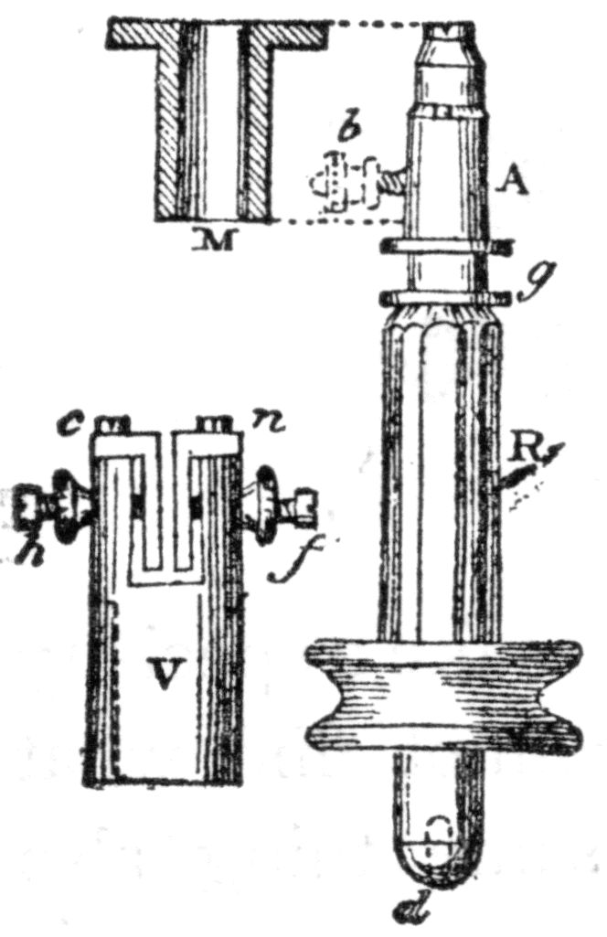
Fig. 187.
Hard steel caps of the form shown at M may also be fitted to A, a notch being cut in them to receive the screw b. These will be found useful as guides for filing or polishing screw-heads, or the ends of arbors flat, reducing the heads of several screws to the same height, etc.
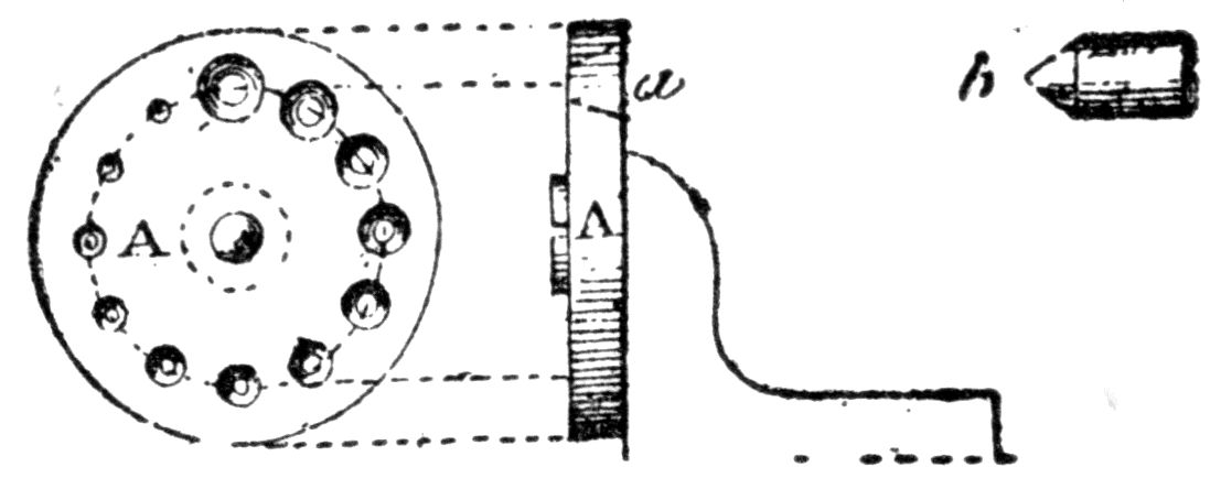
Fig. 188.
395. The tool for forming the U-spaces in a cylinder escape-wheel can be easily be converted into a screw-head tool with laps. A glance at Fig. 189 will at once make this evident. A number of chucks are adapted to the arbor A, and in the tube c c either a T-rest or a spindle carrying a lap is fixed.
It will also serve as a tool for drilling; a drill-chuck with drill, f, being adapted to A, and the object to be perforated at b resting against a plate that projects at right angles from a slide d d, which may be advanced by a screw g.
396. The modern watchmaker has so little call to cut screws that it does not pay him to purchase a screw-cutting lathe; for a very small sum he can have screws of any thread or diameter cut by those who make a specialty of such work, always provided that he cannot find what is wanted in the material stores. The same thing also applies to fuzees.
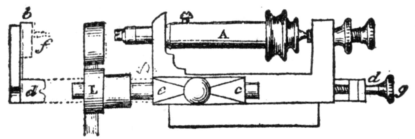
Fig. 189.
TOOLS FOR CUTTING AND ROUNDING-UP THE TEETH OF WHEELS. WHEEL-CUTTING ENGINE.
397. The machine for dividing the circumference of a wheel, termed the wheel-cutting engine, and one form of which is shown in Fig. 190, is well known to nearly all workmen. The wheel is fixed to a chuck at B by wax or screws, or by the pressure of a hollow cone or “sugar loaf” of steel, to the apex of which pressure is applied by the arm D, or in other ways. The wheel may be centered either by a pump-center within the chuck or by an appliance such as is shown in Fig. 191, except that the arm b is curved and its index much longer. This little addition may be fixed to the frame of the engine in any convenient position.
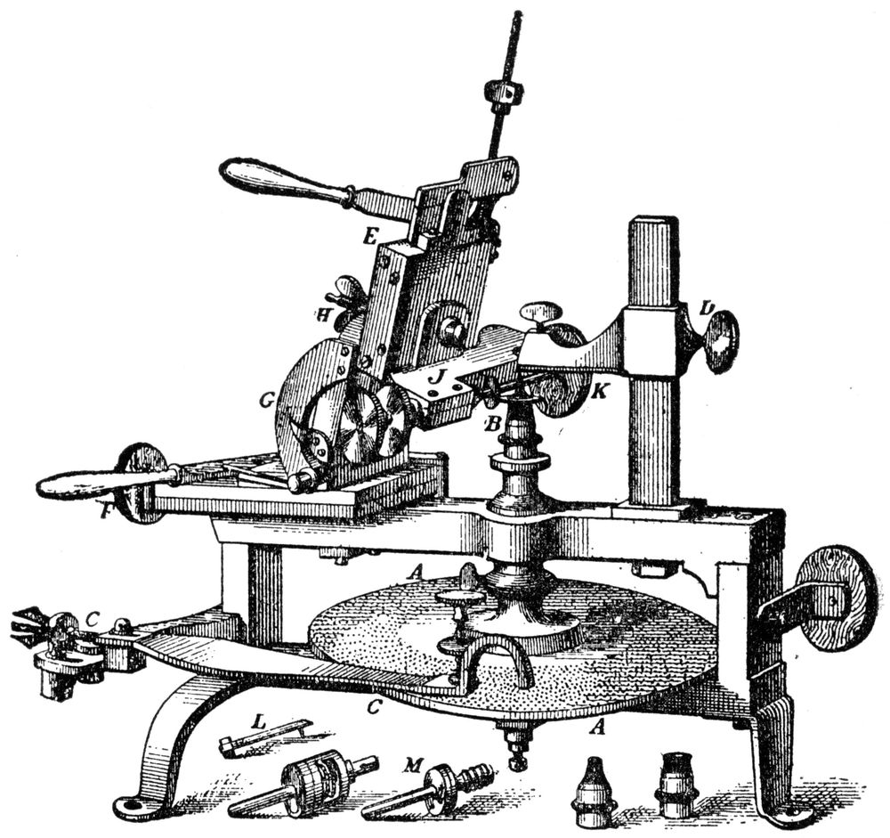
Fig. 190.
The chuck B that carries the wheel is rigidly connected with a large brass plate A A, on which are concentric circles of divisions, and the whole can be maintained stationary by setting the point of the index C C in any desired hole on the division-plate. The cutter is carried on an arbor (shown separate at L) between horizontal bearings in the frame J, and is caused to revolve by means of the pulley K. The several parts lettered E, F, G, H, are for bringing the cutter against the wheel and modifying the direction in which it moves, so that the machine can cut straight or inclined teeth, bevel or crown wheels, etc. It should be added that the engine here represented is more complex than those ordinarily used for cutting watch wheels, although the principle on which it acts is the same.
The teeth may be cut by circular cutters of the nature of files, by a small straight cutter, similar to those used in a slide-rest projecting from a rotating axis, or by several such cutters mounted on a disc which is caused to rotate. For the sake of distinction it will be well to refer to the first of these as file or mill cutters, while the second and third may be termed respectively single and multiple blade or composite cutters.
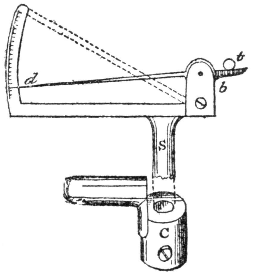
Fig. 191.
Watchmakers rarely possess a sufficiently large assortment of file-cutters for making all the various forms of teeth that are met with in horology; but this deficiency can be supplied by making them for themselves to any required pattern in the manner subsequently described.
398. Observations. The wheel-cutting engine in which the plate is caused to rotate by means of a tangent screw is usually the most accurate. If the pitch of the screw is fine it will give all the subdivisions of a circle that are required for ordinary work, but it is essential that a good form of counter be attached to the screw, and a certain amount of calculation is always needful.
The engine that has a division-plate with conical holes arranged concentrically over its surface is simpler and better adapted for rapid work. The larger this plate, the greater is its chance of being correct and, at the same time, it affords room for a larger number of divisions.
It is preferable that the cutter frame rise and fall in a vertical dovetail, for when the arbor is carried in an H shaped arm pivoted on two screws, the teeth are always slightly dished. The entire apparatus should be somewhat heavily constructed and supported on a solid bed; so as to prevent the vibration of the cutter-arbor from being distributed over the entire machine.
The highest numbers on the plate should be used whenever it is possible, so as to diminish the error due to irregularities in the sub-division. For example, in cutting a wheel of 30 teeth, use the 90 or 120 circles, taking every third or fourth hole.
These remarks will probably be sufficient to enable any watchmaker who possesses a wheel-cutting engine to employ it with success; we will, however, add the description of a few appliances or processes that have a bearing on this question.
399. To Divide a Wheel so that it has one Tooth more or less than any given number on the Division-plate. It is to be observed that neither this nor the following method is mathematically exact, but if it is practiced with care and the division-plate is of sufficient diameter, the error may as a rule be neglected.
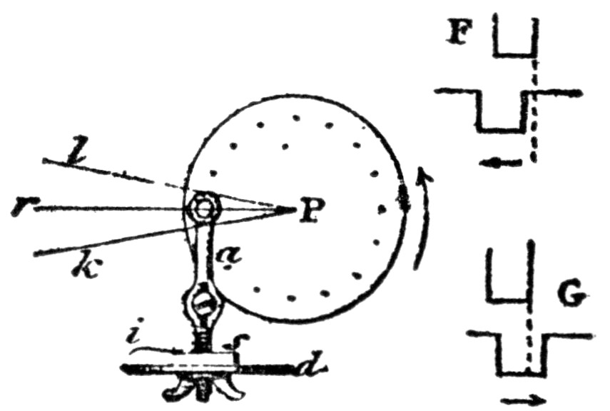
Fig. 192.
Let P, Fig. 192, be a division plate that has a 30 circle, but not one of 29 or 31 divisions. Divide the circumference of a disc d, seen on edge, into a large number of parts in the engine, 360 for example, and fix it to the end of the index, at the same time attaching a finger, i, to the support s. Now advance the screw of the index through a distance corresponding to the angle l P k included between the two successive points of the 30-division circle. To measure this distance a pointer should be previously fixed to the frame to correspond with the middle point of a hole in the circle under consideration, and the motion should be arrested when it coincides with the next succeeding hole. Assume that this amount of displacement has required three complete turns of the screw; 1,080 divisions on the disc have thus passed under the finger i. Dividing this number by 31, we obtain 34.83.
After observing the division on d that coincides with the pointer i, cut the first space of the wheel; then cause 34.83 divisions to pass under i, in such a direction that the plate is drawn with the arrow, and transfer the index to the next hole of the circle, rotating this time opposite to the arrow; the second space can now be cut, and so on.
With a view to diminish errors arising from the omission of fractions, since 31 does not divide evenly into 360, a number of multiples of the number 34.83 should be determined. Thus 4 times 34.83 is 139.32, so that, when the fourth space is cut, the pointer i must be at this number of divisions from its initial position.
The index should be so situated that, when half the arc l k has been traversed, as explained above, s a is at right angles to the radius P r of the division-plate. If it is desired to move d in a reverse direction, it must be moved backwards to a considerable distance and then forward up to the required point so as to avoid error due to backlash. The screw of the index should fit the support s firmly and without any shake.
400. To Cut a Wheel with any Given Number of Teeth. When the given number does not occur on the division plate, proceed as follows: Take a strip of metal, for example a pliant piece of soft steel, and cut in it a series of equal and equidistant notches as shown at B, Fig. 193. Cut the band to such a length that it has the same number of pairs of teeth and spaces as the wheel is required to have teeth. Now turn a lead disc of a diameter that the strip of metal will exactly enclose; fix this strip round the circumference with pins, screws, or in any convenient manner, as is shown at C. We thus obtain a temporary division plate which can replace the permanent one or be attached to its upper or under surface, and, when an index has been adapted to it, the wheel can be divided into the requisite number of parts.
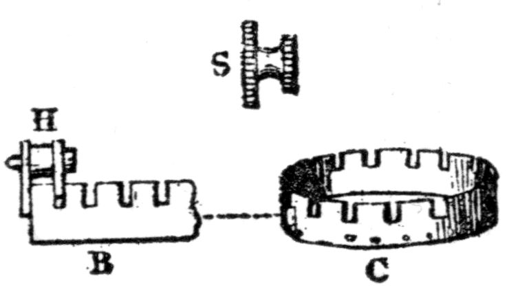
Fig. 193.
When employing an engine the division plate of which is worked by a tangent screw, the above affords an easy means of making the divided head for the screw with any desired number of divisions.
401. With a view to insure accuracy, it is advisable to employ a disc of large diameter as the errors of division are thereby rendered less important and the metallic blade can be made to lie closer to the rim.
The blade is subdivided by a saw to which a guide is attached as indicated at H, Fig. 193, or the saw can with advantage be replaced by a file that only cuts on its edge and not on either face, or by a pair of mills or revolving cutters united together as shown at S. The following plan, however, appears to be more expeditious and to involve less trouble to ensure accuracy.
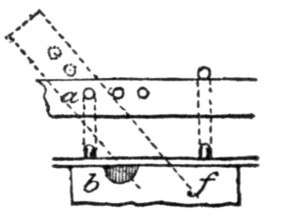
Fig. 194.
A hole a, Fig. 194 is drilled in a metallic band by means of a semi-cylindrical drill fixed in the chuck of a lathe or in a wheel-cutting engine, etc. It will be convenient if the drill can be set vertical. Beneath it is a brass bed-plate in which are fixed two pins equal in diameter to the hole a; this hole having been placed over one pin b, the band is held firmly against the other, while the second hole is drilled. This is then transferred to the pin, and so on.
In the absence of a suitable tool, a well made measure can be employed for marking a series of points with the aid of an eyeglass; the holes are then drilled with the bow or in any other manner.
402. To Cut a Wheel, Ratchet or Pinion on an Ordinary Lathe. When only a moderate degree of accuracy is required, the ordinary lathe can be adapted for cutting the teeth of minute wheels, ratchets, pinions, etc., by making the following appliance:
The piece B, Fig. 195, provided with a stud at p, slides on two horizontal and parallel cylindrical rods fixed to the slide C, or it may move in a dovetail. The cannon d, carrying a ferrule k and a file-cutter f, rotates on the foot at p without shake; and the cord of a wheel or bow passes round k.
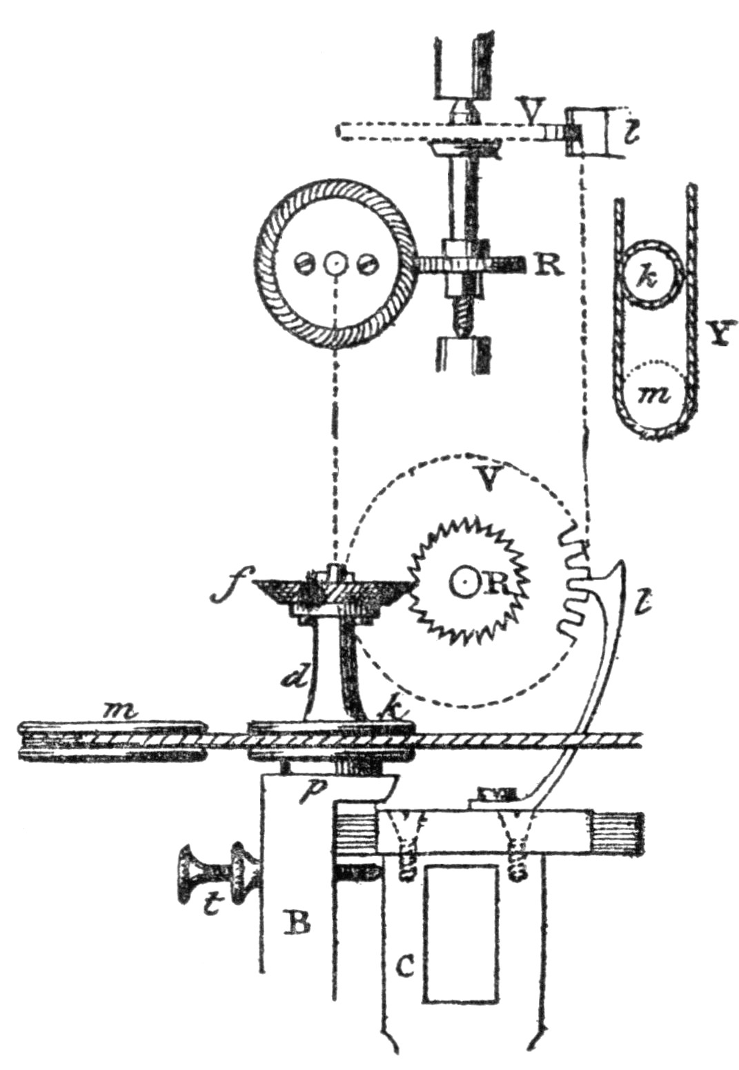
Fig. 195.
R, the wheel to be cut, is supported between the runners, the divided plate V, which may even be an old wheel with the required number of teeth, being fixed to the axis of R. V is held stationary during the operation of cutting, by the index l. The mode of action hardly requires explanation: while f is rotating, advance B until it is arrested by the stop t; then draw B back, advance l to the next division on the plate, and so on.
403. We have said enough on this subject to enable any watchmaker to make such a tool, modifying it or completing it according to his requirements. We would only remark that: (1) If a cannon of the form d is used, the stud should be diminished in diameter at its middle part for about three-quarters of its length, so that friction occurs only at extremities; and (2) if a wheel is used to rotate k, there should be an idle pulley at m supported on a fixed arm independent of B, either attached to the lathe-bed or bench, or fixed in the vise, so that the ferrule k can move backwards or forwards without altering the tension of the cord, in the manner indicated at Y.
404. Wheel-cutting Arbor-chucks. These appliances are specially useful in making wheels that are required to be rigorously true, such, for example, as escape wheels. The form is represented in Fig. 196.
It is simply the arbor of an ordinary lathe, formed in two pieces, b a and b c, the body b d being very accurately fitted into the conical hole in the plate of the wheel-cutting engine. If now a wheel is fixed with wax on the extremity z and turned in the lathe to the required form, it is only necessary to unscrew b c and introduce b d into the socket of the wheel-cutting engine; then having cut the teeth, the piece b c is replaced, and the whole is set in the lathe, if required to test its truth, without the wheel having been displaced from the chuck.
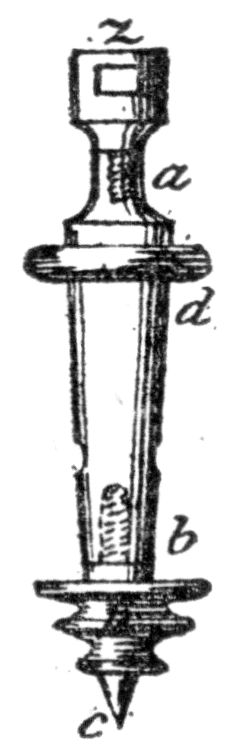
Fig. 196.
It will, of course, be evident that the two parts must be accurately fitted together; the tapped hole and the screw must be true with the axis. M. Millot, with whom we have seen this form of arbor in use, has not been able to detect any eccentricity, although he often employs them.
405. They might be formed in one piece, as a d b, with a point at p. A boxwood ferrule is then fitted onto the portion b d, where it is clamped by two screws, and these can be released when it is desired to insert the chuck into the wheel-cutting engine. The points of these screws should be received in recesses in order to avoid the production of any roughness on the surface of b d.
Wheel-cutting engines have been made to receive these arbor-chucks without removing the pulley. The point c is placed in a hole and the upper end is enclosed in a collar, which is tightened by means of a screw.
The arbor used by M. Millot had a lantern chuck, and this is very convenient in making objects that require to be measured during the progress of the work.
406. Modification of the Ordinary Arrangement for Holding the Wheel While Cutting. In the wheel-cutting engine as usually met with, the wheel (when not mounted on an axis) is held against the chuck by a hollow steel cone, on which presses an arm that slides on a vertical pillar and can be clamped in any position. The hole at the end of this arm does not always, therefore, correspond with the point of the cone, and, as a consequence, the wheel often gets displaced during cutting. This inconvenience can be avoided by adopting the following device, which we have seen in use with several watchmakers.
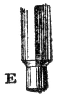
Fig. 197.
The pillar with its sliding arm is replaced by an iron or steel piece of the form G, Fig. 197. The point a is received by the central hole at the lower end of the division-plate axis, while the screw b presses on the point of the cone, clamping it firmly. Further explanation seems unnecessary; we would only add that the piece G must be made strong and perfectly rigid.
CUTTERS FOR FORMING THE TEETH OF BRASS WHEELS.
407. For making the teeth of the wheels of a train, a special form of cutter, set to revolve on an axis, is employed, and it may be constructed on either of three distinct systems.
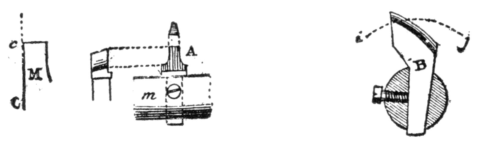
Fig. 198.
Fig. 199.
(1) A single cutter mounted on an arbor, as at A, B, Figs. 198 and 199; this may be termed a single cutter.
(2) A circular cutter, formed of a series of such single cutters, which will be termed a multiple blade or composite cutter. Two specimens are shown at F, J, Fig. 200.
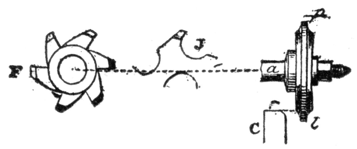
Fig. 200.
(3) The pinion, or steel wheel cutter or mill, formed of a single piece of metal, as seen in Figs. 201, 202 and 203. These may be described as mill or file cutters.
408. To Make a Single Cutter. The form shown at A, Fig. 198, is roughed out to as nearly as possible the required form in good steel. Some makers, possessed of exceptional skill, make them entirely by hand, and they make very beautiful teeth by this means; but as a rule watchmakers cannot look for such success, so that it is better to complete the formation of the cutter in a specially arranged tool.
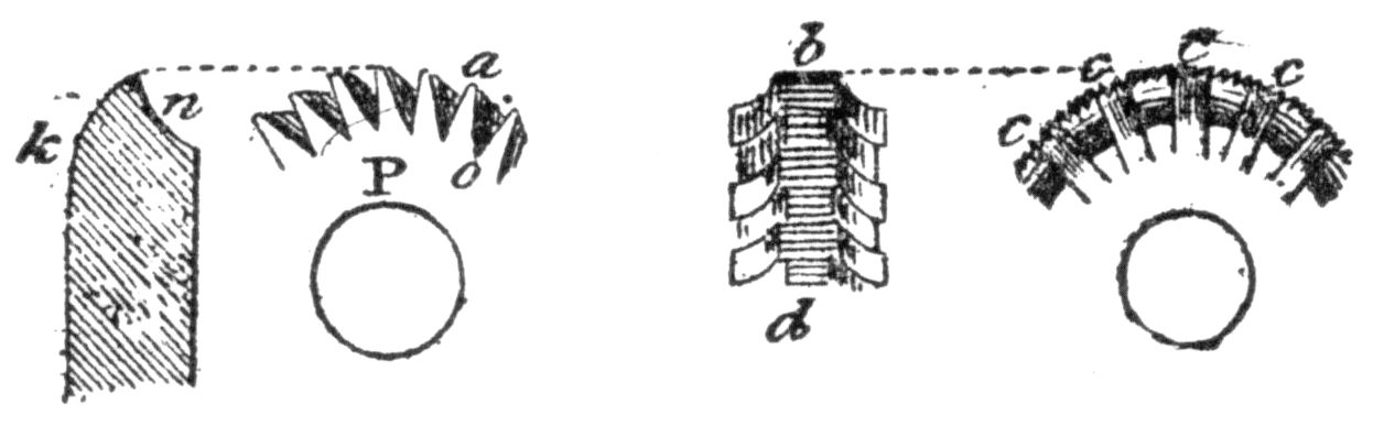
Fig. 201.
Fig. 202.
The two sides may be made in the wheel-cutting engine, with the same mill cutter, which is inclined when used to undercut the acting edge; but this operation is not as easy as it appears at first sight, and the watchmaker will find it to his advantage to make the following device:
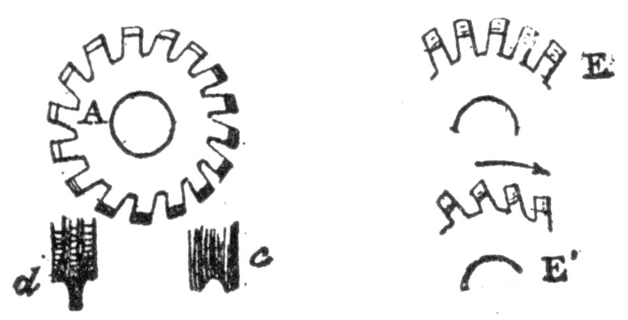
Fig. 203.
A spindle, b d, Fig. 204, supported between the runners, t, v, serves as an axis for the arm f g h, which is bent at g so as to afford a support to a conical cutter a, driven on the ferrule c. The descent of this arm is limited by an adjustable stop, fixed to the bed of the turns.
Having removed the T-rest, replace it by the rod N, to which the cutter is clamped by a screw k, after being roughed out so as to reduce the work required of the cutter.
Place N so that the conical cutter occupies the position indicated at z, and, if a slight pressure be applied at h while a is caused to revolve, both the straight and curved portion of the side will be formed, and the side will, at the same time, be bevelled to an angle corresponding with that of the cone. The curved portion of the side will be more or less undercut, according as the arm h is depressed below the horizontal plane passing through the axis of the lathe. The opposite side is formed by inverting the piece f g h.
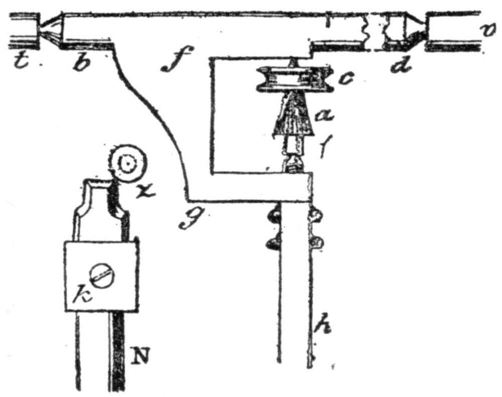
Fig. 204.
In smoothing or polishing it is only requisite to replace the cutter by a smooth conical roller, and to work as before.
409. The cutter is sometimes fixed in the arbor as shown in Fig. 198. The arbor itself is thick and perforated with a round hole in which the tail of the cutter accurately fits, a slight pressure applied by the screw m being sufficient to make it steady.
For cutting the escape-wheels of clocks the arbor should have a velocity of about 200 turns a second.
M. Peupin, a skilful watchmaker who adopts the practice here given, having observed that with a sharp cutting edge he did not obtain a sufficiently smooth surface, succeeded in obviating the difficulty by drawing a polisher with rouge along the cutting edge, maintaining it at right angles to the plane of the cutter. This operation, if carefully executed, will serve to remove the feather-edge, to make the edge even and yet not dull, and to secure a highly polished cut surface. The sides of the teeth will present a proportionately better surface, according as the portion c a (M, Fig. 198,) approximates towards the dotted line c d.
His escape-wheel teeth are cut in successive stages. The last stroke of the cutter is given by advancing it against the side of the wheel, so that the cutter axis remains in the plane of the wheel.
410. Triangular Cutters. When a cylindrical or conical mill is not available for finishing and sloping the sides of a cutter, it may be replaced by a triangular cutter (T or C, Fig. 205,) and when the application of much force is required there may be a pointed bearing; but this is seldom necessary.
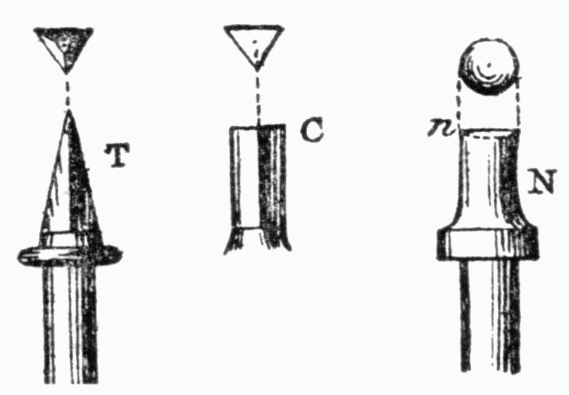
Fig. 205.
If carefully hardened and set, such a cutter gives a clean cut; of course it will not act for as long a period as the conical form above described, but this is of comparatively little importance, since the blank cutters are always roughed out previously to nearly the requisite shape.
411. To Make Several Cutters at Once. By adopting the following method, it is possible to make several such cutters in one operation.
Turn a steel disc of the form of an ordinary mill cutter, as shown at l p, Fig. 200. To finish it, giving the same curvature to the two sides, take a piece of steel, C, and shape the corner r to exactly correspond with the side of the point or ogive of a tooth, bevelling it so as to give a cutting edge at the upper surface; then harden and smooth it with care. Having fixed it in position in the tool that carries the arbor a and the roughed out disc (whether this be the lathe, wheel or pinion-cutting engine, or a special device) in the required position, one side of the disc may be finished. The arbor a is then reversed and the other side finished in the same manner, so that both sides have the same curvature in opposite directions.
Of course the tool C may be advanced against l p, either sideways from r towards l, or radially in the direction l p, as is most convenient. Or the tool might remain fixed and the disc advance against it radially or laterally.
The traverse slide in a lathe is usually provided with a stop; it would then be very easy to form one side of the disc in such a tool, afterwards reversing the arbor and forming the other side.
If a very good cutting edge is desired, the sides should be smoothed and, when the disc is completed, it may be divided into pieces similar to B, Fig. 199, each of which will serve as a cutter. It will be noticed that the acting edge is not undercut behind; it is thus necessary to slope the cutter a little as shown at B, as otherwise the rim will choke in the spaces of the wheel, straining it without cutting.
412. Composite Cutter Formed of a Succession Of Single Cutters. By mounting a series of identical single cutters round the circumference of a disc, a circular cutter can be formed in the manner indicated in Fig. 206. The upper portion represents the arrangement of the pieces while they are being turned, and the lower portion shows their positions when the cutter is ready to be used. M. A. Croutte, to whom we are indebted for several of the details here given, was much surprised that this form of cutter is not better known, since it possesses certain special advantages; we will summarize his remarks on the subject.
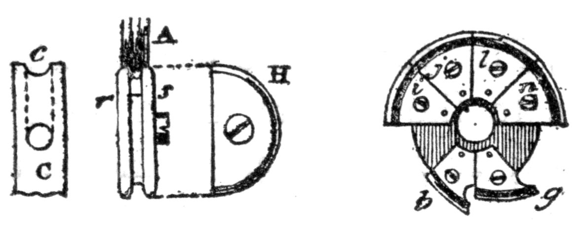
Fig. 206.
The separate cutters b, g, etc., Fig. 206, are not undercut from the acting edge backward; they are merely reversed, so that this acting edge is towards the front, in other words it lies along the radius. These separate pieces possess a special advantage in that they can be used until the steel is quite worn out by the setting; in this respect differing from the undercut cutters, for they are not altered either in form or thickness by setting.
As a set-off against this important advantage, they are characterized by the inconvenience of requiring that the two sides of the blade be exactly in a plane at right angles to the axis, and that the slide carrying the cutter-arbor shall move in a direction parallel to this plane. And even when this double condition is satisfied, there will be friction of the two sides above the dotted line i j, Fig. 199, against the sides of the teeth; and if the above named conditions are not satisfied, the cutter, being presented edgeways, will be choked with brass, and the results will be unsatisfactory.
413. In order to ascertain whether such a fault exists, it is only necessary to notice whether the cutter becomes brass-colored on one side towards the point, and on the other more inwards, and the sides of the teeth exhibit striæ or scores in opposite directions, as indicated at E, Fig. 207. The white strip, 1, 1, corresponds to the bottom of a space between two teeth; 2, 2, and 3, 3, the two sides of this space, spread out like an open book.
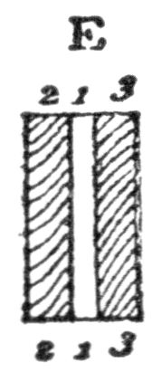
Fig. 207.
By examining the marks with care, and noticing the direction in which they are inclined, it will be possible to ascertain both whether the separate cutters are out of place, and in which direction the arbor should be moved in order to correct any error.
We must, then, repeat that all the cutters must satisfy this condition, because if only one is wrong it will produce the scores here referred to.
The necessity of these precautions in the use of such a composite cutter, and the fact that the friction of the portion above the line i j, Fig. 199, renders it difficult to obtain a polished cut (which is essential for such delicate depths as those of watches), have doubtless prevented its use becoming general. For work that is somewhat larger or rough, it will be found to give satisfactory results and will last longer than a single cutter. A lubricant, such as glycerine or oil, should be applied to it.
414. Composite Cutters with the Cutting Edges Undercut. An old Paris clockmaker, Brisson, used a cutter of the form F, Fig. 200, for the teeth of his wheels. He undercut the two sides of the blades by means of a small special tool. Strictly speaking, the operation can be performed by hand.
In order to ensure that the curves that form the ogives of teeth are alike on the two sides of a cutter, he made a series of templates or standards of the form C, Fig. 206, in which were two holes, C and c, of equal diameter. The upper one, which might be funnel-shaped so as to give a cutting edge, was half cut away, and, after being hardened and set, could be used to give a final stroke to the circumference of two discs of equal diameter. These two discs, or one cut through a diameter would suffice, having been brought by a file to the form H, and joined as shown at r s, can be mounted eccentrically so as to present a cutting edge to the roughed out cutter A; the two sides can thus be made even. The disc may then be finished by cutting away the metal so as to give the form shown at F, Fig. 200.
By the aid of the standards he could easily reproduce the same forms of teeth when required.
Fig. 200 comprises, at J, a cutter for the teeth of watch wheels of the form employed successfully by M. A. Phillippe. The figure will explain itself.
We have known a Geneva wheel cutter who employed these composite cutters with advantage in making duplex wheels. The principal difficulty he experienced arose from the distortion of the metal in hardening, because the acting portion naturally lengthened a little. This form of composite cutter certainly demands careful workmanship, but, if the construction, hardening and polishing are good, it will produce fine work and will last a long time.
415. General Observations on Cutting the Teeth of Brass Wheels with a Single or Compound Cutter. High-class English watches, the movements for which are made at Prescot, in Lancashire, have the wheel teeth made by a composite cutter after the wheels are riveted to their pinions. We have remarked that these watches make less noise when running down than those in which the teeth have been formed with a mill or continuous action cutter.
Success in forming teeth with cutters depends mainly on the securing of a good form as regards the cutting edge, and on its being maintained in good condition; on the steadiness of the entire machine, so as to avoid vibration; on the weight of the wheel, and on the velocity of the cutter being sufficient. A cutter ought never to assume a brassy color except when it requires setting; if it does so, and this is not the case, it proves that the metal is being strained or scraped with friction. The velocity must be very considerable; greater with a single cutter than with one that is composite. The velocity is limited by that point at which the heat generated would cause the oil to evaporate, soften the cutter, distort, and sometimes even displace, the wheel operated on. The engagement of the cutter with the metal must be very slight, and should never be increased suddenly.
Attempts have been made to enclose the arbor bearings in horn, but it is liable to be distorted by the heat.
Before dividing the disc into cutters it is essential that the two edges be carefully smoothed, and this without their being distorted. This can easily be done in an old depthing tool, using an arrangement like that shown in Fig. 208. The lap must be of hard wood, and its right-hand corner rounded off so as to resemble the side of a tooth; it is set to engage with one side of the cutter. We say the right-hand corner, because a lateral pressure can then be applied. It is important that the surface as left by the graver be clean cut, because if the smoothing is too much prolonged, it will deform the cutter.
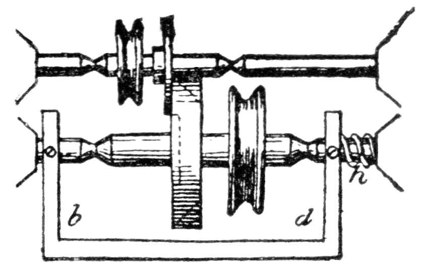
Fig. 208.
416. In some factories it is usual to use discs about 2½ inches in diameter, for cutting the teeth of brass wheels in timepieces. The single cutters are arranged round the circumference as follows: One forms a space between two teeth; the one immediately preceding forms the right-hand side of the ogive, and that which follows forms the left-hand side. By adopting such an arrangement of separate cutters, if their side that lies against the disc is slightly inclined backwards it is no longer necessary to bevel off the cutting edge.
MILL CUTTERS FOR STEEL.
417. Pinions, Keyless Wheels, Etc. The cutters that last for the longest period when used for cutting steel are those formed like a file; but a watchmaker is not always in a position to make them himself; we will, therefore, here only speak of those he can make, the description of the first few being taken from a work by M. A. Phillippe, of Geneva, Les montres sans clefs (keyless watches).
418. Cutter for Forming the Inclined Teeth of Winding Pinions. Fig. 201 shows at S a section along the axis of such a cutter, and at P a side view. When it is believed to be of the required form, rest a piece of lead on the T-rest of the lathe and press it against the rotating disc. The impression made in the lead will afford a means of ascertaining both whether the form is correct, and whether the surfaces are smooth enough. This last point is important.
The cutting edges are formed by merely making a number of notches around the circumference with a tool for cutting ratchet teeth. Then advance this ratchet cutter so that it may engage with the convex edge of the cutter operated upon, and against the back of the teeth of this cutter; the ratchet cutter is then in a position to form a second face, o i, by which the teeth of the cutter are undercut at the back, but in such a manner that a small flat surface o a is left in order to retain the form. When a cutter made in this way will no longer bite, it may be set by passing a hard slip of whetstone over the faces of the teeth.
The ratchet cutter employed for making this cutter should never be pressed against it heavily.
419. Cutter for Ordinary Wheel Teeth. We will now pass to the consideration of cutters for forming teeth of the usual shape, of intermediate steel wheels, set-hands wheels, pinions, etc. They may be made as follows:
The rim is indented with small fine ratchet teeth, b d, Fig. 202. Any burr produced on the sides is then carefully removed, and the cutter is placed in the wheel-cutting engine, and notches, c, c′, c′′, c′′′, etc., are formed on either side with a flat square-edged cutter of such a thickness that the circumference is about equally divided into hollows and prominences. It is important to note that the right side of the teeth must be but slightly roughed, not more than is required in order to raise a slight burr, all that is necessary to form the cutting edge of this portion of the disc. In roughing these sides, at least one out of every two of the small ratchet teeth on the circumference should be left untouched, so as to ensure the required thickness being maintained.
The cutter shown in section and elevation at S and P, Fig. 201, might be cut on the side n in the manner here explained, and the convex portion k might be indented with a fine ratchet-toothed cutter, carried in the hinged cutter-frame of the wheel-cutting engine. The degree of penetration may be determined by fixing an ivory disc against the cutter and concentric with it, the two differing in diameter by the depth the cuts are to be made. The teeth will be rather too square towards the circumference, but their form can be carefully corrected by hand. It is obvious that the very greatest caution is necessary in hardening cutters.
420. Rose-Cutters or Forming Pinion Cutters. As the edges of pinion cutters are rounded, they can be made in the manner suggested by Thevenin. Supporting the roughed out cutter in the cutter-frame of a wheel-cutting engine, he fitted in the axis of the division-plate a kind of rose-cutter, N, Fig. 205. Its extremity, n, instead of being flat, is hollowed out as indicated by the dotted line, and, by presenting the cutting edge thus obtained endwise to the grooved edge of the cutter, the correct form can be given to it. With a mushroom-headed piece of steel and oilstone dust, the cutting edge of the rose-cutter can be made more or less acute by modifying the angle of this steel lap.
421. Other Forms of Pinion Cutter. When a cutter is merely required for a special piece of work, and not for continuous use, it will often be sufficient to make it as shown at A, Fig. 203; this is made by grooving the disc (c), or forming its edges as at d, after which a series of teeth are cut on the periphery with a revolving cutter, taking care to leave no more burr on one side than on the other. Then pass a smooth worn file (or a worn flat cutter) over the faces of the teeth, applying oil at the same time, so as to produce a slight burr on the edges; if the file is not allowed to bite too much and is well managed, these minute ridges will be uniform. After hardening, the cutter is ready for use.
If the faces were smoothed without subsequently applying the file, the cutter would not bite; for its action depends on the slight projection of metal that corresponds to the file-cuts. The cutter is nothing more than a circular file, with two cuts per tooth. If the corners are turned over evenly by means of a very hard burnisher the same effect will be produced; but this operation is delicate, as the amount of metal turned over must be the same in every case.
When a cutter does not bite, it must be softened and restored to its initial condition.
422. Or the following method may be adopted when it is required to make a cutter for a special purpose.
Proceed at first in the manner just described, but the periphery is divided into a greater number of teeth with a flat cutter, and to a rather greater depth, as at E, Fig. 203. Bend backward each tooth to a distance equal to about half a space by any convenient method; for example, by a lever resting at the bottom of each space and pressing against the corner of the tooth, etc. Before bending the first tooth introduce a piece of brass into the space behind it, of a thickness equal to about half this space, so as to avoid bending too far; for succeeding teeth the thickness must be about equal to a space; thus E will become E′. An inspection of Fig. 203 will suffice to make the operation evident; it amounts to bending back a series of separate cutters. The disc is then hardened, and the faces of the teeth are smoothed when they do not cut well; or merely smooth those that are the first to become dull.
It is important to employ soft steel that has previously been well annealed.
423. Cutter for Making Square Spaces. The teeth of such a cutter can be easily formed with a file, as shown at L, Fig. 209, the edge of the cutter, f, being passed backwards and forwards in the direction of the arrows, applying considerable pressure and at the same time slowly rolling f around. Or the cutter may be set up on a short arbor between the centers of the lathe; then pass the file backwards and forwards across the edge until the cuts are formed, slowly advancing the file in the meanwhile, so as to form the cuts around the circumference without once raising the file. The cutter must then, of course, be hardened.
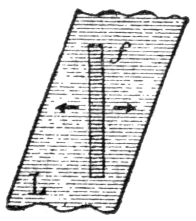
Fig. 209.
424. Forming Cutters with a Milling Tool. The roughing of a round-edged, or even of a square cutter, can also be effected with the aid of a milling or “nurling” tool, proceeding in the same manner as when milling the heads of screws, etc. The tool must be in good condition, well provided with oil, and applied with considerable pressure against very soft steel.
If necessary, the workman can make the mill for himself; it is shown at M, Fig. 210. F shows the method of applying it to the cutter, and by partly turning the mill (of course carried in a strong holder) around its point of contact with the cutter, as indicated by the dotted lines, the rim of F will be evenly roughed all around.
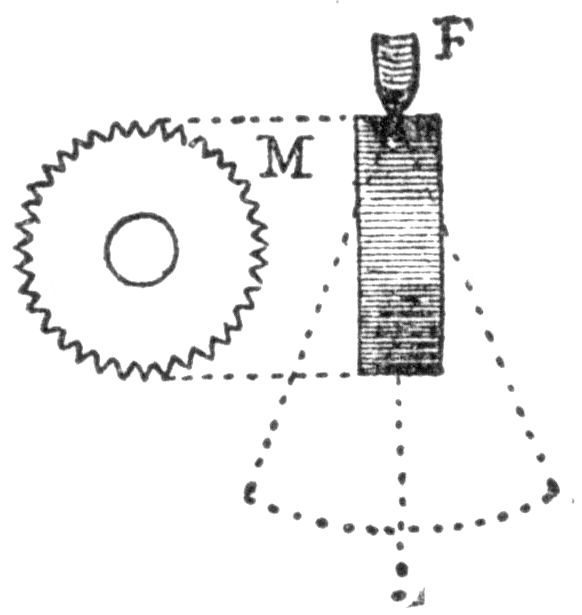
Fig. 210.
With good steel fairly satisfactory results are obtained in this manner, but it is needless to observe that such cutters never bite as well as those made in the usual manner.
425. General Observations. When cutters are used with steel they must be driven at a less velocity than when cutting brass, and, as M. A. Phillippe has observed, it is best to make the cutters for steel of small diameter (about half an inch). They are more easily made and are less distorted in the hardening. The velocity should diminish as the diameter increases; for too great a velocity, especially when the diameter is great, will dull the cutter and soften it, owing to the heat produced.
Cutters must be turned very true: it is advisable to give them a last stroke with the graver after they are fitted to the cutter-arbor that will subsequently carry them.
When operating on steel it is best that the cutter frame of the wheel-cutting engine be advanced by a screw so as to give it a slow and easy motion; the results obtained are more satisfactory than when it is advanced by hand or with a lever.
The following practice is not uncommon in factories when it is desired to reproduce the exact form of a cutter. A notch is made with the cutter in the edge of a piece of steel, X, Fig. 211, or a series of notches o o′, etc., can be made by several cutters in the circumference of a disc Z (same figure). After being hardened and sharpened at the cutting edge, this disc is fixed at the center of the division-plate of a wheel-cutting engine, and can then be used to complete the grooving of any cutter that is set in position on the cutter-arbor before hardening. The positions opposite to which the notches were cut should be marked on the chuck, so that they may always be set-square to the cutter.
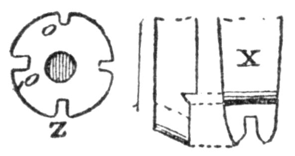
Fig. 211.
426. Besides the forms of cutter above described for operating on steel, we may mention that circular cutters may be used in which all the notches around the circumference have been polished, thus removing the burr, and preventing them from acting in the manner of a file. But while, with the former kind, a somewhat rapid rotation is necessary (although not so rapid as when cutting brass), with this latter class the movement must be comparatively slow, and produced by means of a hand-wheel; otherwise they will not cut, since the action depends rather on the application of pressure, and resembles that of a slide-rest cutter. The distance apart and width of the teeth of the cutter, as well as their inclination, are of importance; if too far apart they occasion a waste of time; if too large the machine will act in a jerky manner, and when too narrow, an excessive pressure will be needed in order to make the cutter bite the steel, which, it is to be observed, must always be thoroughly annealed. The edge must be well supplied with oil or soapy water when in action.
It is generally found best to advance the cutter against the edge of the steel rather than across it.
TOOL FOR MAKING CUTTERS.
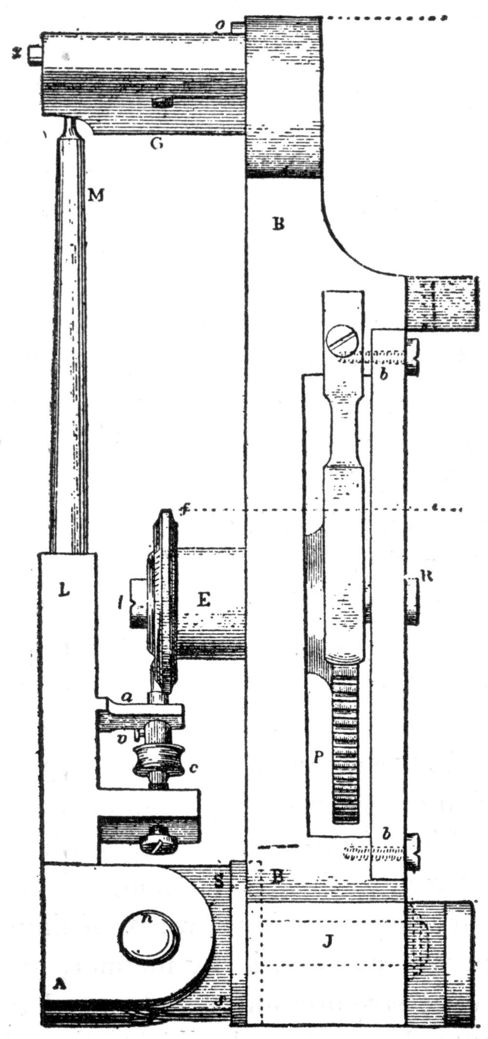
Fig. 212.
427. The instruments usually employed for making cutters for the teeth of wheels and pinions are complicated and expensive, but the author has designed one for his own use that is comparatively simple, and can be made by any watchmaker. When the reader has grasped the principle on which it acts he will be able, without difficulty, to modify it so as to suit his requirements.
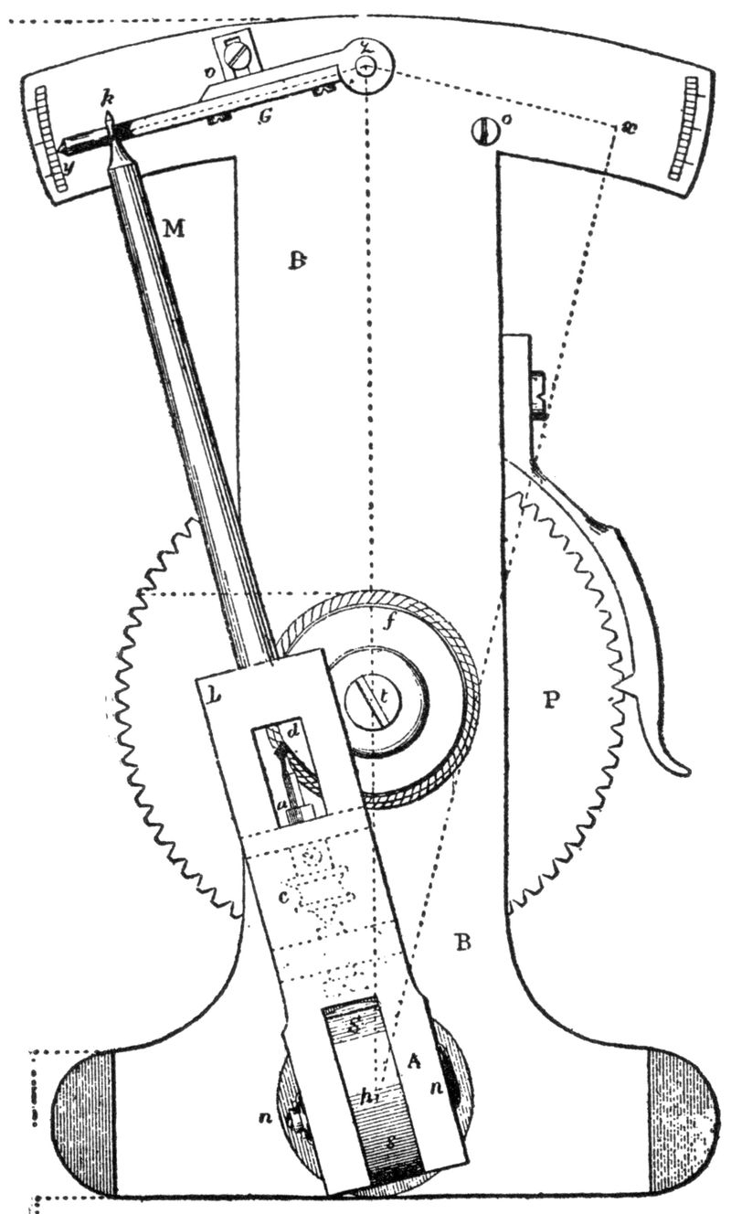
Fig. 213.
The frame B B b, Figs. 212 and 213, consists of the body of the tool, B B, and a bar b b, which is attached to it by screws. Between the two the division-plate P rotates on an axis E R. The end E of this axis is formed as a chuck to receive the cutter f, which is clamped by a screw t.
The support S s J is held with friction in the lower part of this frame, to carry the cutter-holder A L M. This cutter-holder is hinged at n, so that it can receive a double motion, revolving about a horizontal axis J, and about an inclined axis n.
The portion A L of the cutter-holder carries a perforated arbor a c, with a ferrule c that receives the tail of the small rose-cutter, which will presently be described.
The end M rests against a guide G, held by a vane o z, which is pivoted on a pillar z, and can be clamped in either of the directions z y, z x, or by one of the screws o, o.
428. We will now consider the mode of action of the machine. Having set the little arbor c a in rotation, rest the end M of the arm against the guide, and gradually advance the rose-cutter towards f; the edge of d will form the first notch in the grooved rim of the cutter, and then will be raised from contact with it, owing to the influence of the guide G. After moving the tool-holder back to its initial position, advance the wheel P by a tooth, repeat the operation, and so on.
429. If the cutter f has to be notched on both sides, it must be reversed on the chuck; turn the guide so as to point in the direction z x, corresponding exactly to z y; then having set the cutter-holder in the line z h, recommence operations. The two grooves of the cutter will then necessarily be of similar form.
Teeth can be cut on the rim of f by using a cutter of the form F, Fig. 214, and holding M against a straight vertical guide.
With a given divided wheel, P, the teeth can be brought nearer together by reducing the diameter of the cutter, and vice versa. It is well to have some change wheels, but a better plan is to advance the division plate by the aid of a tangent screw.
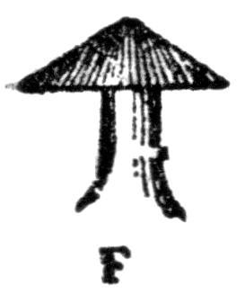
Fig. 214.
430. To Make the Several Accessories. Form of the rose or star-cutter. The rose-cutter is formed of a mushroom-headed piece of steel. Such a conical cutter is shown at C and R, Fig. 215, and at F, Fig. 214. F and C are cut in the same way that conical cutters are always made, and R is a small triangular prism that only cuts by its three corners, a, a, a. As it is necessarily very small when employed in making the cutters for watch pinions, it must, in such a case, be supported at the neck by a little fork. Moreover, it must be brought gradually against the steel to be operated upon, so as only to engage a very little at a time. With a view to this, it is advisable that the cutter-holder be advanced by a screw.
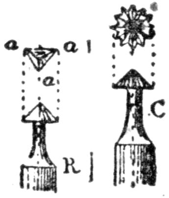
Fig. 215.
The star-cutter, shown at E, Fig. 216, is at times substituted for the rose-cutter. It cuts with the corners e, e, etc., whether it be going to the right or left indifferently. Or a triangular cutter like T, Fig. 216, can be used in its place; but its angles are fewer and less acute, so that they become dull more rapidly.
A few trials will be needed in order to determine the most convenient rate of movement of the several parts; and the edge of the cutter f must always be liberally supplied with oil. A little can may be so arranged as to allow oil to fall drop by drop on to the cutter d, Fig. 213.
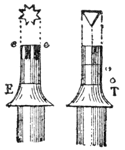
Fig. 216.
431. To make the guide. Having mounted a plate, G, on the vane o z, trace out the approximate form of the cutter with the point of M; then cut off the superfluous metal, leaving a slight margin. This excess is necessary because the curvature of the guide is not the same as that of the cutter, for the indentations as they spread out from the center (t) become gradually deeper. The guide should be tested from time to time by operating on a blank brass disc fixed in place of the cutter f and the guide must be modified as experience shows to be requisite. Its edge must be saddle-shaped so that the middle may correspond exactly with the two dotted lines z x, z y, Fig. 213.
The position of the disc on the chuck t must be brought to correspond with the guide by carefully turned washers placed behind it.
432. Driving attachment. Fig. 217 shows one system that may be adopted for connecting the ferrule C with a driving wheel. All that is required is that the instrument be set in such a position that this ferrule is placed as indicated in the figure with reference to the distributor.
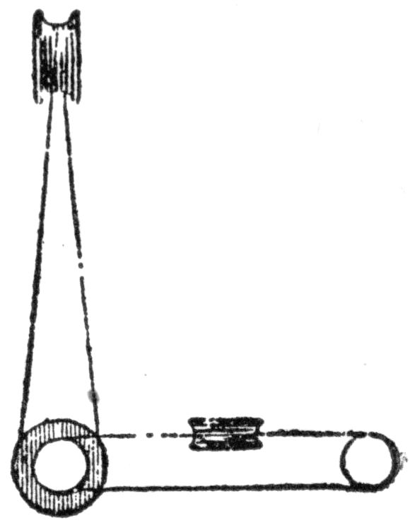
Fig. 217.
433. Cutters of uneven thickness at the circumference. It is well-known that the edges of the cutters of rounding-up tools (435) are made to taper off around the periphery. In order to indent such a cutter, the guide must be mounted on a slide, so that it may be gradually displaced while the operation is in progress, by an amount previously determined upon.
The desired result can be obtained with sufficient accuracy by moving the guide backwards by successive stages with a screw. The end k of the arm M, Fig. 213, is slightly tapered, so that a gradual depression of M occurs, and each cut is deeper than that which preceded it.
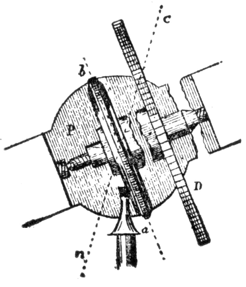
Fig. 218.
434. Modification in the construction. This instrument may be modified as follows: The disc to be operated upon is fitted to the chuck of the division-plate D, Fig. 218, which is vertical, and the entire system is capable of a movement of rotation round the axis of the base P. Having set the disc in the plane a b, as shown in the figure, clamp P; then, by traversing the cutter-holder, the teeth on the side of the cutter towards a b are made. This cutter frame having now been removed, the base P is turned until the cutter is in the plane c n, such that it is equally inclined on the opposite side of the axis of the cutter frame; the teeth on that side may then be made, the star-cutter being rotated in an opposite direction.
It is unnecessary to prolong our explanations of the instrument, as the details already given will suffice for any intelligent workman.
TOOLS FOR CORRECTING THE FORM OF TEETH.
435. Rounding-up Tools. In Europe it is the practice, in making watch wheels, to first notch the circumference by means of a flat circular cutter in a wheel cutting engine, thus forming a number of square teeth. They are subsequently rounded off to the usual form, after the wheels are riveted to their pinions, in a special tool.
The apparatus employed for this purpose is termed a rounding up tool, and its principal feature is a mill cutter F, Fig. 219, the portion a b of whose circumference is cut away and replaced by a guide g f made of steel spring, and so fixed as to coincide with the edge of the cutter at f, and incline at g in order to compel the cutter to pass, at each rotation, into consecutive spaces of the wheel. Two screws are provided, the one f for setting the guide opposite the edge of the cutter, and g for placing the free end of the guide opposite to a space.
This tool acts with great rapidity, a fact which has led to its being very extensively used in the factories of France and Switzerland, although the ordinary system of wheel cutting is preferred in England for all the better class of work. For it should be noted that the rounding up tool does not correct any errors that are due to bad dividing; for example, if a wheel is found to have some of its teeth larger than others, the tool can not be relied upon to correct them; on the other hand, if a wheel is exactly divided it is improbable that the employment of this tool will occasion irregularity.
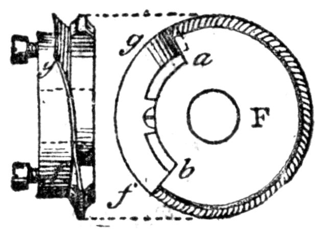
Fig. 219.
The instrument we are discussing is, however, not much used by watch repairers, although they are frequently called upon to touch up the teeth of wheels, or to slightly reduce the diameters of their pitch circles, operations which cannot be done by hand with much chance of success. The limited use to which rounding-up tools have been put is owing, in great part, to their high price, but cheaper tools on this principle are now coming into use.
436. One of these is shown in Fig. 220. The wheel to be operated upon is held against a small table at D between two vertical runners with guard-pivot centers, and a cutter of the form shown at Fig. 219, is fixed at C to a suitable chuck of a small lathe-head B; this is caused to revolve by the hand-wheel A, a supplementary pulley K taking all strain off the axis. The three milled-headed nuts seen at E, F, and G are for adjusting the instrument; E for moving the lathe-head, so that the cutter is in the same plane as the axis of the runners, a position which is determined by the pointer I; F for advancing the wheel against this cutter; and G for setting the plane of the wheel to pass through the axis of the lathe-head as indicated by the index H. The instrument is accompanied by a number of cutters to suit the various sizes of teeth ordinarily met with, as well as of tables to support wheels of different dimensions.
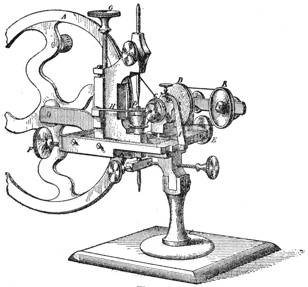
Fig. 220.
437. Ingold Fraise or Cutter. Rounding-up Cones. Either the cutters devised by M. Ingold, or the rounding-up cones of M. Berlioz, may be used for correcting the form of wheel teeth.
The Ingold fraise is a small steel cylinder perforated through the axis so as to be mounted on an arbor, and having a number of longitudinal notches on its circumference which makes it resemble a pinion, the points of whose leaves have been ground off. The spaces of the fraise are of the exact form required to be given to the teeth of the wheel, and their surfaces are covered with fine file cuts so as to enable them to remove metal from the wheel operated on.
Having mounted the arbor that carries it between two centers of a depthing tool (made especially strong for the purpose), the wheel is supported by its axis between the second pair of centers (with guard-pivot points). If now the fraise be advanced by the screw until its teeth engage with those of the wheel, and either be caused to rotate, it will drive the other, and the fraise will thus shape the teeth to a pre-determined form, the faces of each notch acting the part of a minute file introduced between the teeth.
It will be observed that such an instrument is preferable to the ordinary rounding-up tool, in that it may be relied upon to bring all the teeth to the same shape, but, on the other hand, the latter tool has an advantage in being available for slightly reducing the diameter of a wheel when a depth is found to be too strong.
438. An objection has been urged against the Ingold fraises on the ground of expense, as each dimension of tooth evidently requires a cylinder specially adapted to it. This fact has led to the introduction of “rounding-up cones” the invention of M. Berlioz, which act on precisely the same principle, but are conical instead of cylindrical, so that each fraise evidently takes the place of a number of Ingold fraises. The total number being proportionately reduced. But great dexterity is required in their use, so that they cannot be successfully employed until after numerous trials.
439. Exact Rounding-up Tool. The author has devised an instrument for giving to the teeth of wheels the exact form determined upon by theory, but as it is of too elaborate a nature to come into general use, we shall not do more than here refer to it. It is rather of a nature to be used for scientific work, but might be found of considerable value for accurately forming the blades of cutters that are used in grooving the circular cutters employed for cutting the teeth of wheels.
440. To Round Up Teeth By Hand. We have seen a country watchmaker proceed somewhat as follows: His method was only effective, however, for ensuring the verticality of the file, and did not maintain it straight, nor could the curvature of all the teeth be relied upon to be the same; these two conditions are satisfied by the system here explained.
Formerly watchmakers possessed very considerable skill in this kind of work, as the teeth were always formed by hand; but at the present day, for want of practice, there is not one to be found in a hundred competent to round up a wheel properly by hand alone. Recourse may be had to the following expedient in an emergency; it necessitates the construction of a small special tool, but this is so simple that it can be made in a few hours by an apprentice.
441. Take a bar of metal or hard wood, made smooth on its faces and square at the corners (R, Fig. 221), and adapt to it a slide, c c, through the center of which a slot is cut to receive a clamping screw; it slides between the four pins indicated in the figure. An arbor a is supported by c c, parallel to R, having a plate at its end on which a wheel to be operated on can be fixed by three screws and a loose plate. It is centered by the circumference before clamping these screws, rotating a with a bow, and it may be well to place a piece of tissue paper under and over the wheel in order to avoid scratches. V is a tongue that can be introduced into the space between two teeth in order to prevent the wheel from moving.
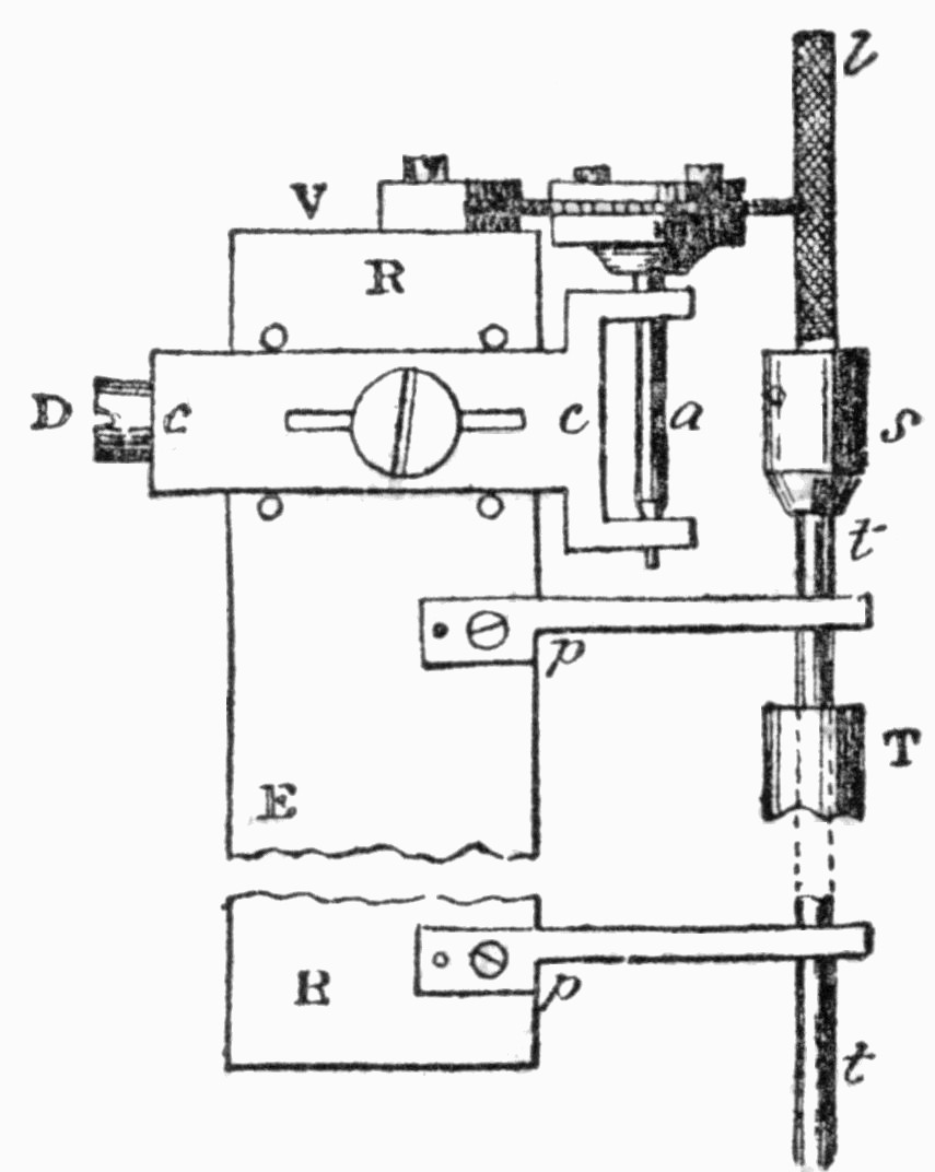
Fig. 221.
Two arms, p p, screwed to the bar R R, support the handle of the rounding-up file l, which consists of a large cylinder t, t, that slides in the arms p, p. The cylinder T must be exactly parallel to the arbor a, and the longer it is the better. The file-holder s, also shown detached at Y, Fig. 222, is merely driven onto the rod t. The distance between the center of the axis t and the face of the file (b b′, Fig. 222) is equal to the radius of the circle that embraces the external curves of two or more teeth, as will be explained.
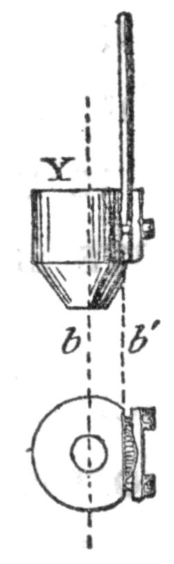
Fig. 222.
The several parts being arranged as shown in Fig. 221, and the bar clamped in a vise at E, it will be obvious that, if the wheel is held in two fingers of the left-hand so as to prevent it from being displaced, while the rod T is moved up and down, at the same time rotating it with the right-hand, the curves of two teeth will be adjusted to correspond with the arc o o o (Z, Fig. 223), and, by transferring the tongue V to the next succeeding space, the curve i i i can be struck.
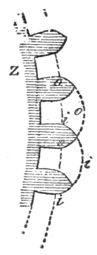
Fig. 223.
442. Observations. The curvature of the point of a tooth coincides very closely with a circular arc described from a certain definite center, and comprising either two or three teeth. In order to realize these conditions in practice, the slide c c is so adjusted that the axis of T passes just within the circle that passes through o, o, o, etc. (Z, Fig. 223), at which the points of the teeth commence; by making trials with two or three file-holders that differ in regard to the distance b b′ (Y, Fig. 223), it will be easy to select the most suitable for producing the required curve. After operating on all the teeth in succession, advance the wheel by means of the screw D, and again work around the circumference, and so on. The progress of the work should be frequently examined with the glass.
It is possible to dispense with the tongue V, and to merely steady the wheel by hand; the work is thus done more rapidly, but must be examined with very great care.
We would insist that the lengths of the two axes are an element of success. In operating on watch wheels T should not be less than six inches long.
By suppressing the tongue the motion of the two axes may be co-ordinated so as to form any theoretical curve; This is the case in the exact rounding-up tool already referred to, but it of course renders the instrument more complicated.
443. To Ease a Train of Wheels. In very many of the cheaper watches and timepieces now met with in commerce the teeth are rough and badly cut, and the pinions but little polished, so that watchmakers are constantly complaining of the difficulty of securing even a moderately good depth. In such cases they have a simple method to adopt in addition to those already referred to, namely, to polish the teeth with a piece of charcoal.
A piece of smooth, even charcoal, with regular fibre, is moistened with oil or water, and passed across the teeth individually; first with the fibres lying in the direction of motion, and afterwards with them at right angles to that direction.
If the charcoal is carefully selected and lightly applied for a sufficient length of time and no more, the ogives will be found to be nicely smoothed, and the depth will run far more easily than it did previously. It is dangerous to use quick-cutting charcoal, as it is apt to deform the teeth.
Smoothing with a brush charged with charcoal powder cannot be regarded as anything more than cleaning; if the action is too much prolonged the form of the teeth will be spoilt.
TO TEST THE ACCURACY OF CERTAIN TOOLS.
444. Drilling Tool. First center the runner in the lathe, and ascertain that it is straight, cylindrical, and exactly centered; then fit a ring to it so as to slide with friction to (temporarily) limit the descent of this runner in the vertical stock of the tool.
After placing it in position, adapt to its lower end a collar, provided with a long index of soft brass, which is bent so as almost to touch the plate at its circumference. Rotate the runner and it will be shown to be perpendicular to the plate if the point of the index remains at the same distance from the plate.
As a confirmatory test the runner may be drawn up in the stock, and the trial repeated after bending the index nearly to touch the plate.
445. Uprighting Tool. If the two stocks or tubes that receive the runners are exactly in line, a runner should move easily through the two at once.
Setting the points in contact in various positions in a vertical line, observe whether they coincide, both when at rest and when rotated together or independently.
First ascertain that the table is at right angles to the axis in the manner already explained for the drilling tool, making the necessary tests with the two runners independently. Then support between their points a short arbor carrying a soft brass index. The position of the lower runner being maintained constant by means of a collar as above explained, rotate the upper one by hand; its friction will carry the index and arbor around, the point of this latter being set close to the plate. Repeat the operation by raising the pair of runners and bending the index down to the same amount.
If in these various positions the point remains at the same distance from the table, it affords evidence that the tool is accurate.
An uprighting tool consists of two parts: the table carrying the lower stock, and the bridge that forms the upper stock. The base of this latter is a ring turned flat and co-axial with the stock, and is fitted accurately into a square groove surrounding the table, where it is fixed by screws.
Any watchmaker understanding this mode of construction will easily perceive when he has tested the tool in the manner above indicated, both what are its faults and how far he can correct them.
446. The English uprighting and drilling tools, and some of foreign construction, are combined on the same stand, and a good arrangement, made by Boley, is shown in Fig. 224. It will be seen that the drill can be set in motion by a hand or foot-wheel; the table is fixed in a vise and provided with two dogs for clamping the object. The drilling spindle is perforated throughout its length so that the drill can be held by an American split chuck.