PART IV. TOOLS AND APPLIANCES. (continued 2)
Reading edition
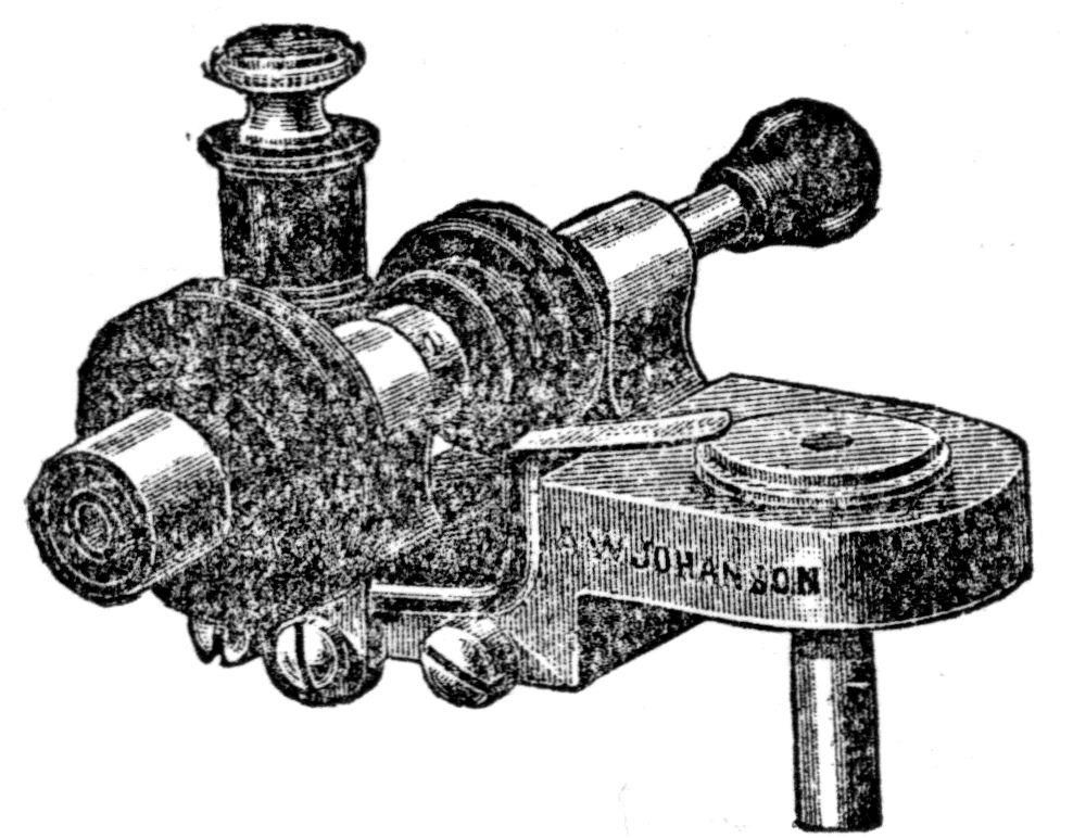
Fig. 113.
Fig. 114.
295. Centering Attachments or Back Rests. These attachments are very useful in rapidly bringing work to an accurate center, when pivoting, staffing, etc., and particularly where a large number of pieces have to be centered successively. Fig. 115 illustrates the Potter patent self-centering lathe attachment which is made to fit any pattern of American lathe.
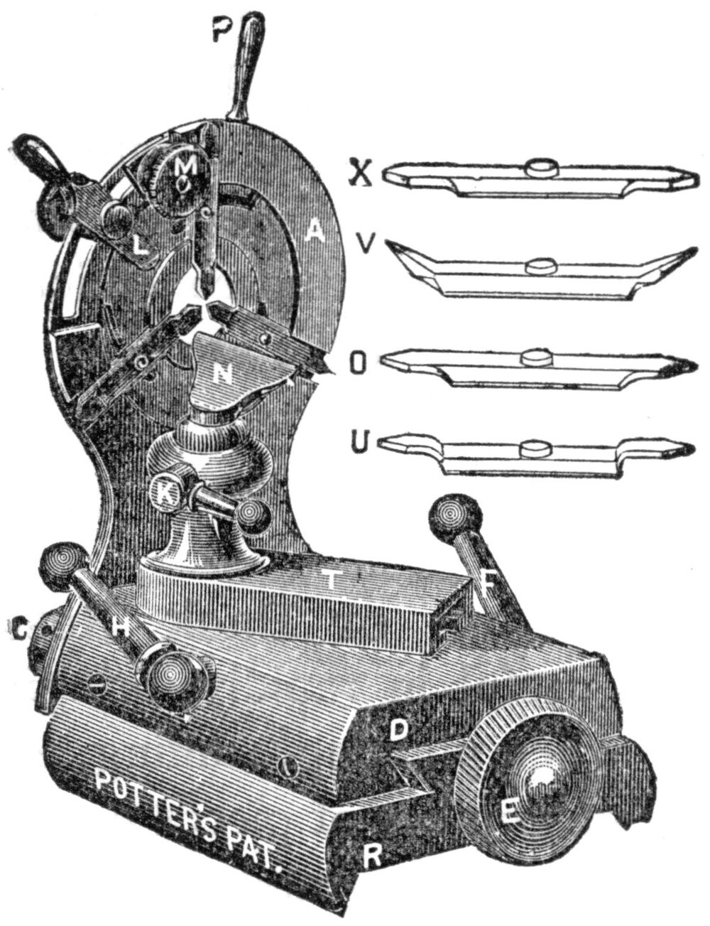
Fig. 115.
It consists principally of the slide bed pieces R and D, the upright plate A and the reversible anti-friction sliding jaws O U V X. The upright plate A is attached to the slide D in such a way that it may be readily raised or lowered, or adjusted in any other direction at pleasure; and may be set with either side facing the lathe-head. The sliding jaws are made of phosphor bronze anti-friction metal and four sets, of three in a set, are furnished with each attachment, as shown at O, U, V, X, the forms differing so they may be adapted to the various kinds of watch work, and they are operated in radial grooves in the upright plate A by means of the rotating lever L, which moves the three jaws in and out, to and from the center, or opens and closes them in perfect unison. One set of jaws may be withdrawn and another set substituted therefor in a few moments. With each change of the jaws, however, the plate A requires readjustment, but this too, may be done in a few moments, as follows: Having previously provided yourself with a bit of straight wire or a small steel rod, turned to run perfectly true in your lathe, and having fastened this in your chuck in the lathe, loosen the nuts C C, so as to give freedom of movement to the plate A; then bring the attachment to proper position on the lathe bed and fasten it there, after which move the sliding jaws inward until they bind tightly on the piece of straight wire held in the chuck and in this position again tighten the nuts C C. Once adjusted to accurate center in this way, no further adjustment, whatever the size of the work to be operated upon, is required, until you make another change of jaws.
In use, the end of the work to be operated upon is placed in an accurate split chuck in the lathe, and the chuck tightened on it, just sufficiently to hold it in place and to rotate it, the other end being supported in the central bearing, formed by the sliding jaws. In this position the jaws may be opened or closed as often as desired, and each time they will bring the work to accurate center.
A similar attachment to the one above described is extensively used by machinists and is known as the back rest. In principle it is very similar, but is more simple in construction, and ambitious workmen can make them without difficulty. This attachment, which is shown in Fig. 116, differs in its mode of fastening to the lathe bed and the jaws cannot be opened and closed at one time as in the Potter attachment.
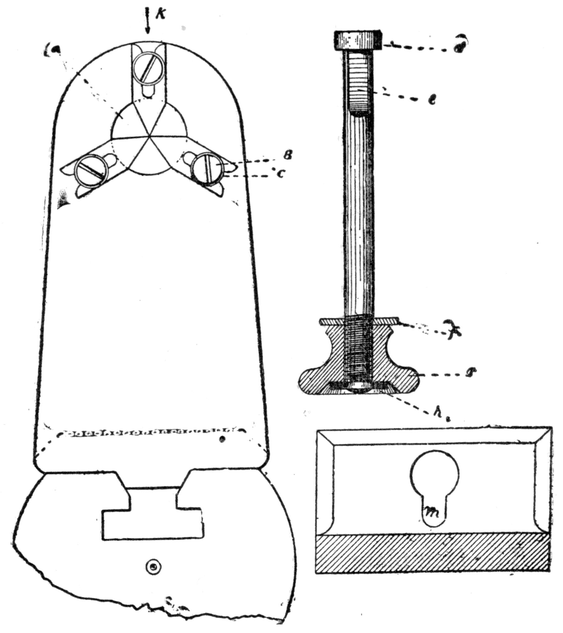
Fig. 116.
The illustration shows the rest in position on the lathe bed, looking from the right-hand end of bed; m shows the base, looking from above, in direction of arrow k; d shows bolt for binding it to the lathe bed. It does not seem as though it needed much explanation, as it will be readily seen that the head d of bolt, passes up through the longitudinal slot in the lathe bed, through the round hole in base of back rest and is slipped back into slot m, when about half a turn of nut g binds it firmly to the bed. The washer h, on the end of the binding screw, is riveted or soldered in place and should be close enough to nut g to allow only about half a turn to loosen the bolt, as that is sufficient, and more space would occasion a loss of time in running the nut back and forth to bind or loosen the rest. It will be seen that when the nut g is slackened, it binds against the washer h, and it will stay there, and be just where you want it when you are ready to use it again. The jaws are of hard brass; about three sets, with points of different widths, will cover a large range of work. Those shown in Fig. 116 are suitable for such work as pivoting small French clock pinions, etc. It will be observed that the jaws are so made that they may be changed by slightly loosening the screws. The screw heads should have thin steel washers under them.
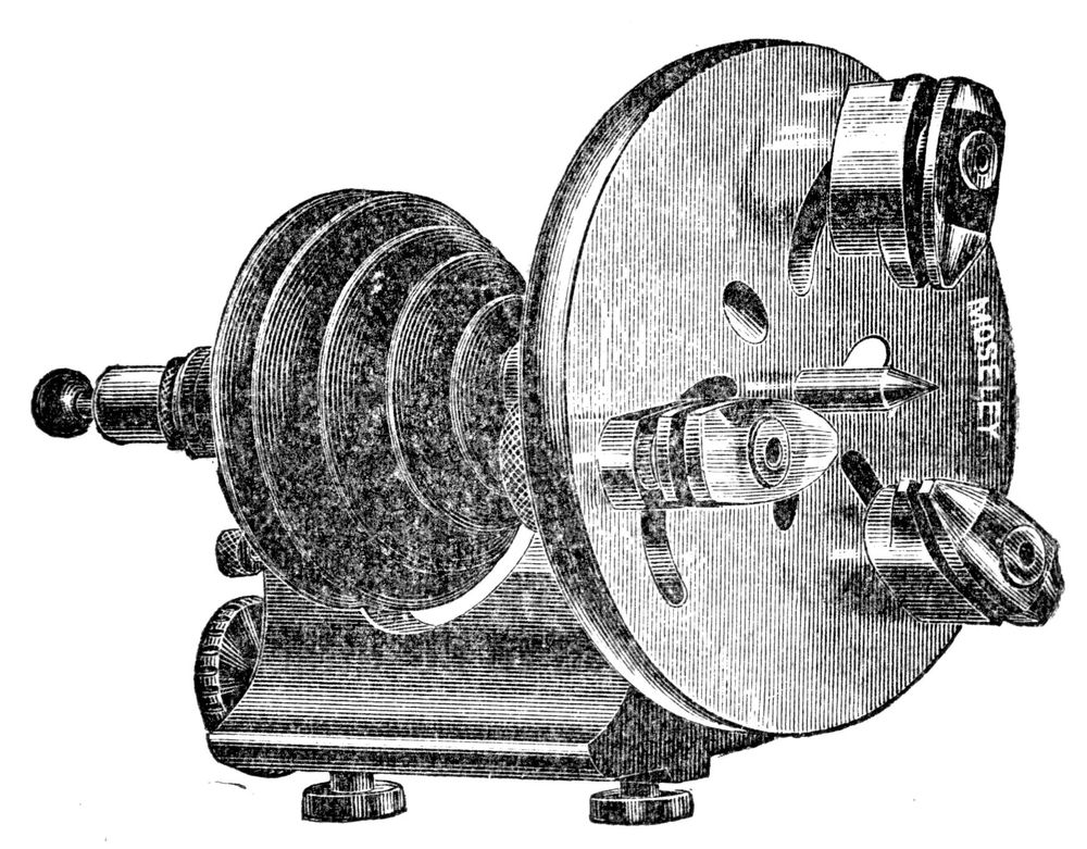
Fig. 117.
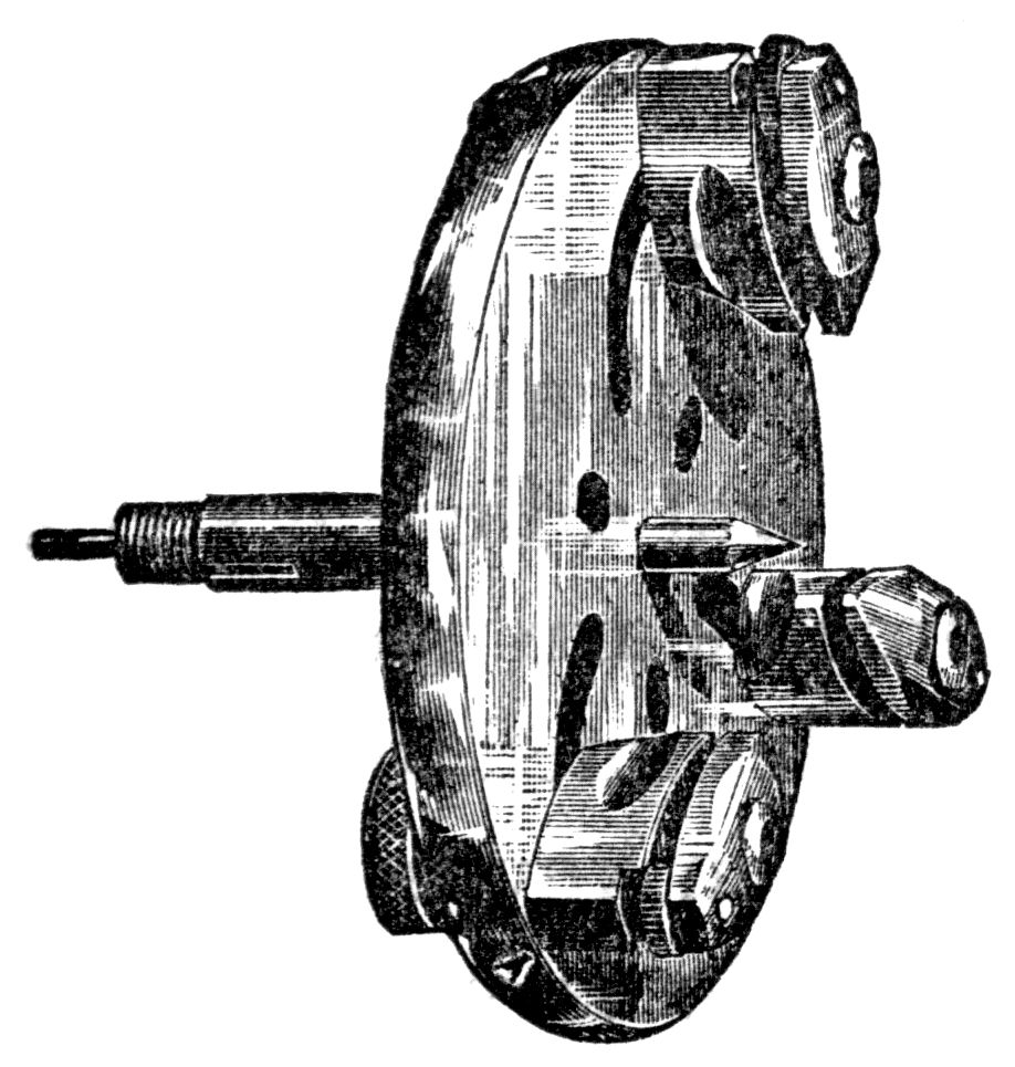
Fig. 118.
296. Universal Head. The universal head has entirely superseded the clumsy universal mandrel in this country. The example shown in Fig. 117 is more accurate, less clumsy and complicated and will perform all the work that can be performed on the universal mandrel. The face-plate is 3½ inches in diameter, but by the use of the two crescent-shaped slots it will hold anything in size and shape of watch work. The pump center is operated from the back by the rubber knob and can be used either with or without a spring. The jaws, which will pass the center, are held in position on face of plate by springs and are fastened from the back. Peep holes are provided in these heads in order that the workman may examine the back of the work at all times. In the Moseley head, shown in Fig. 117, these holes are of taper form. Fig. 118 shows a universal face-plate to be used in a chuck in the lathe. It is smaller and less expensive than the universal head and answers very well for some work, especially that of the lighter kind, but cannot be recommended as highly as the universal head, as it is not so accurate. The pump center is used to center, from the back, any object confined in the jaws, but it sometimes becomes necessary to mount the object, by means of wax, upon a plate, and hold the plate in the jaws. In such a case the work must necessarily be centered from the front. This can be done accurately by means of a piece of pegwood, as ordinarily done on the lathe, by placing the point in the center hole and the pegwood resting on the T-rest and observing if the free end of the pegwood remains stationary.
297. Traverse Spindle Grinder. This tool will be found very useful for grinding cutters, lathe centers, pump centers, reamers, countersinks, squaring up barrel arbors after hardening, or work on any hardened steel tool. In the hands of an ingenious workman, it will be found exceedingly useful, as by its aid a great variety of work can be performed that cannot be accomplished without it. Fig. 119 is intended to be attached to the slide rest.
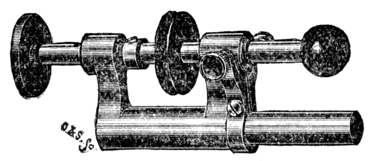
Fig. 119.
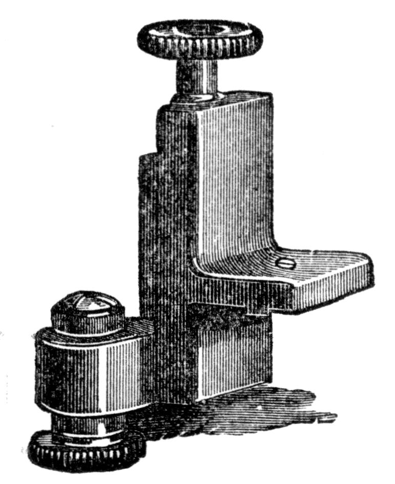
Fig. 120.
298. Milling Fixture. This attachment, which is shown in Fig. 120 is designed to be fitted to the slide rest and holds the wire chuck vertically under the center of the lathe, so that articles held in the chucks can be fed under mills or saws held in the saw arbor in the lathe-head.
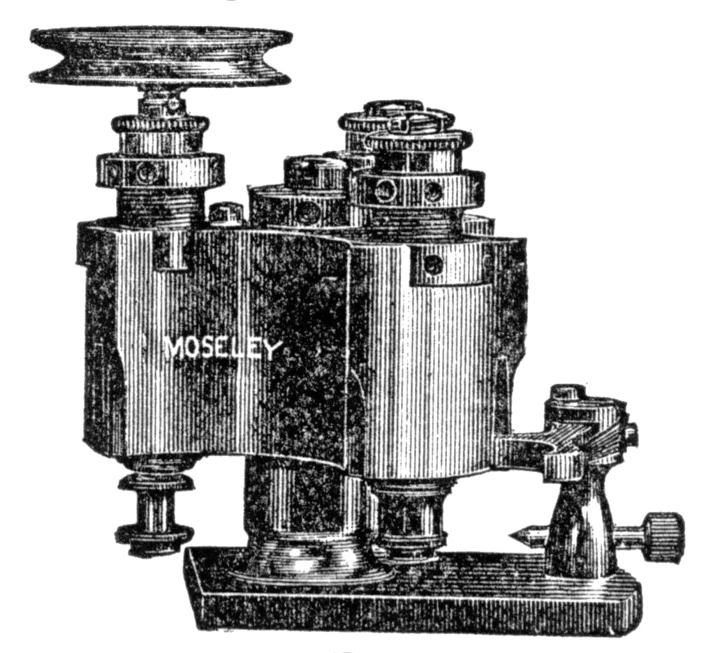
Fig. 121.
299. Wheel Cutters. The wheel cutter is a valuable addition to the lathe. Several different styles of these attachments are made, each possessing points of merit. They are designed for cutting all kinds of wheels and pinions used in key and stem-wind watches. When the cutter spindle is vertical the belt runs directly to it from the countershaft, but when horizontal, the belt passes over idler pulleys held above the lathe. One style of wheel-cutting attachment is shown in Fig. 121, while another style is shown in Fig. 71.
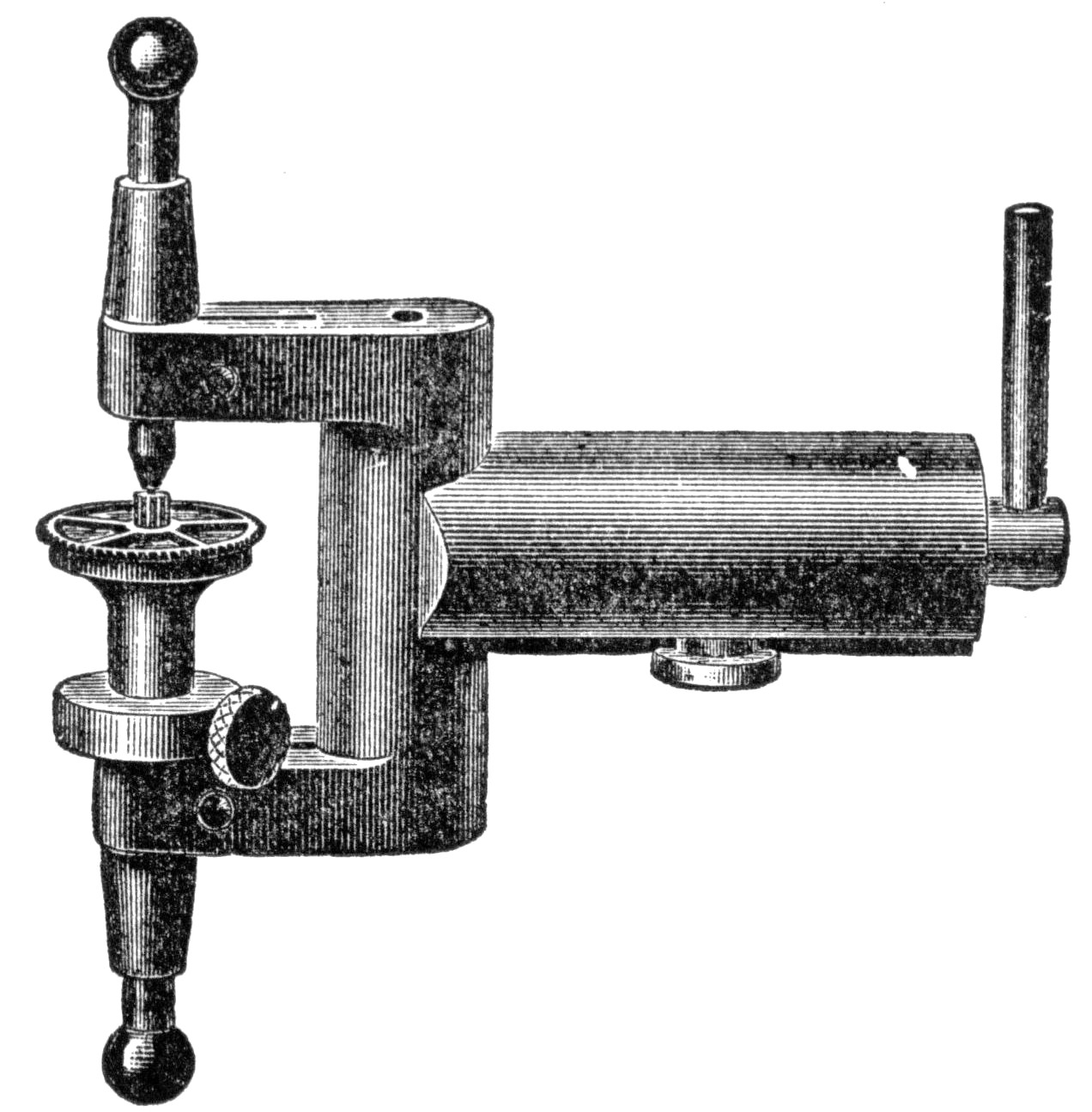
Fig. 122.
300. Rounding-up Attachment. The Webster rounding up attachment, shown in Fig. 122, is a very useful adjunct to the lathe. It is attached to the top of the slide-rest. To operate, a pointed taper chuck is put in the lathe spindle. The wheel to be rounded up is put into the fixture and the wheel adjusted vertically so that the point of the lathe center will be at the center of the thickness of the wheel, after which the lower spindle of the fixture should not be moved. Now remove the wheel, also the taper chuck, and put the saw arbor, with the rounding-up center, in the lathe spindle, and adjust the longitudinal slide of the slide-rest so that the rounding-up cutter will be back of and in line with the center of the rounding-up fixture, after which the longitudinal slide of the slide-rest should not be moved. Now put the wheel and supporting collet in place, and proceed with the rounding-up.
MISCELLANEOUS SMALL TOOLS.
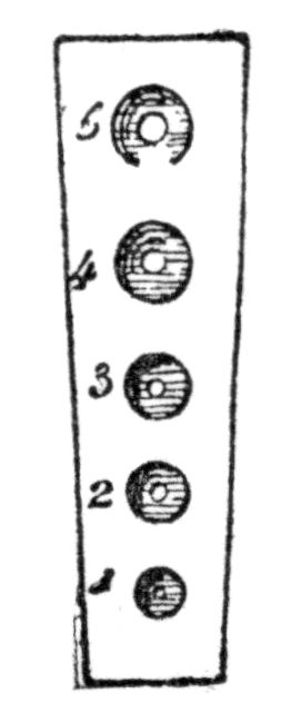
Fig. 123.
301. Screw Head Sink Cutter. This is usually made in the form of an arbor terminating in a cutting edge similar to the rose-cutter, but having a projecting pin from its center. This tool will be found especially useful in replacing broken end-stones. The jewel being set in brass, is held by two screws, on opposite sides, the screw heads being let in or sunk even with the surface, half of the screw head projecting over on the end-stone. The end-stones furnished by the watch companies are not sunk for these screw heads, but are round and of the proper diameter. These cutters will cut away from the jewel setting the space to be occupied by the screw head in a very few moments and in a very perfect manner. All of the watch companies do not use the same diameter of screw head in the cock and potance, consequently you will be compelled to make separate tools for the different makes of watches. With a set of five or six of these cutters you can fit any American watch. After you have completed your set, of say five or six cutters, select a small brass plate and bore five or six small holes in a row, in which the guide pins of the cutters will enter, and then cut with the tools a number of sinks, numbering these holes in the plate and also the arbors of the tools with corresponding numbers. You will then have a plate similar to Fig. 123 which can then be used as a gauge for measuring the heads of screws.

Fig. 124.
These cutters are easily made as follows: cut off a piece of wire of the required diameter, about one inch long, and place it in a chuck that fits it snugly and turn one end to a center, about 40°; now reverse the wire in the chuck and be sure it is true; select a drill that will pass through the screw hole in the cock or potance freely and proceed to drill a hole in the center of the end of the wire, about ¹⁄₁₆ of an inch deep. Remove from the lathe and with a sharp file and graver, proceed to cut a series of teeth as equal and even as possible. Use a good strong glass while working and be sure you have every tooth sharp and perfect, as upon this depends the quick and nice work you expect from the tool. When this is well done, proceed to temper fairly hard and polish up the outside to make it look workmanlike. Now select a piece of steel pivot wire, of a size that will almost fit in the hole drilled in the end of the tool and polish down to the proper size to drive in the hole tightly. Allow the wire to project about ¹⁄₁₆ of an inch, taper the point and polish. The tool is now complete and will resemble Fig. 124. Select an end-stone of a diameter to fit tightly in the cock or potance, as maybe required; set the hole jewel in place and then the end-stone pressed down tightly against the hole jewel. Place your cutter in a chuck that fits it true; select a smaller medium sized drill rest and place it in the tail stock spindle. Hold the cock, or potance, with the jewels in place, against the drill rest, level, and proceeding to run the lathe at a fair speed, slowly feed the cock or potance to the cutter, the projecting pivot in the end of the cutter passing through the screw hole and acting as a guide to keep the cutter in the center of the hole. Caution must be exercised, or you will cut the recess for the screw heads too deep, as these little cutters are very deceiving and cut much faster than you would suppose. In fitting an end-stone, select one that is more than flush when the jewel hole and end-stone are in the proper position, and after sinking the screw head as described, turn off on the lathe almost flush or level. Make a small dot on one side of the end-stone as a mark or guide in replacing it. Remove the end-stone and proceed to polish the top of the setting on a plate glass polisher.
302. Screw Extractors. The Bullock Screw Extractor, shown in Fig. 125, is a simple yet very valuable tool to the watchmaker who finds he has a plate in which a screw has been broken off. To use this tool, first fasten it in your vise, then bring one end of the broken or rusted-in screw against screw center and the broken screw head against screw driver; turn the washers so as to hold the broken screw firmly in place; turn the plate gently and the broken screw will follow the screw driver point out of the plate. It may be necessary in some instances to turn the screw driver point against the broken head with a good deal of force in order to start the screw. A little benzine or kerosene applied to the screw will help to loosen it.
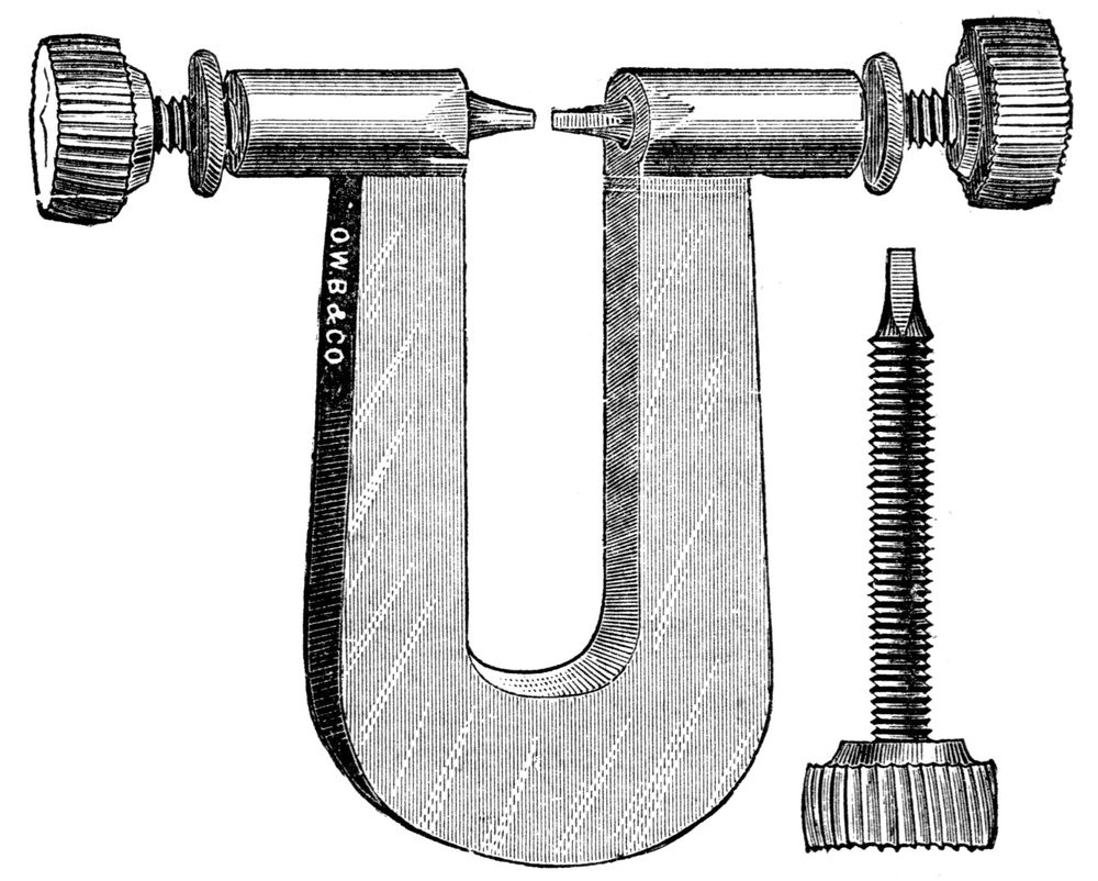
Fig. 125.
The ingenious workman can, with the expenditure of a little time, make an attachment for removing broken screws, somewhat similar to the above. Take two common steel watch keys having hardened and tempered pipes—size, four or five—having care that the squares in each are of the same size and of good depth. Cut off the pipes about half an inch from the end; file up one of these for about one-half its length, on three equal sides, to fit one of the large split chucks of the lathe. Drill a hole in one of the brass centers of the lathe of sufficient size and depth, into which insert the other key-pipe, and fasten with a little solder. Soften a piece of Stubbs’ wire, to work easily in the lathe, and turn down for an eighth of an inch from the end to a size a little smaller than the broken screw in the plate; finish with a conical shoulder, for greater strength, and cross-file the end with a fine slot or knife-edge file, that the tool may not slip on the end of the broken screw; cut off the wire a half inch from the end and file down to a square that will fit closely in one of the key-pipes. Make a second point like the first one and fit it to the other key-pipe; harden in oil, polish, and temper to a dark straw color. Fit the brass center into the tail stock. To use, put the tools in place in the lathe, place the broken end of the screw against the end of the point in the lathe-head; slide up the back center and fasten the point firmly against the other end of the screw, that it may not slip or turn; revolve the plate slowly, and the broken screw, being held fast between the two points will be quickly removed. To remove a broken pillar screw, place the broken screw against the point in the lathe-head, holding the plate firmly with the right-hand, the pillar on a line with the lathe center; turn the lathe-head slowly backward with the left-hand, and the screw will be removed. Should the tool slip on the broken screw, and fail to draw it out, drill a hole in the lower or dial side of pillar, down to the screw point (if the size of the pillar will admit of it), and with the second point in the back center, remove the screw in the same manner as in the first process. Five or six sizes of these points will be found sufficient for the majority of these breakages that may occur.
It sometimes happens that a screw gets broken off in a watch plate in such a manner that it is impossible to remove it with tools without marring the plate. In such an event proceed as follows: Put enough rain water in a glass tumbler to thoroughly cover the plate and add sulphuric acid, until the water tastes a little sharp. Place the plate in the solution and allow it to remain a few hours, when the screw will partially dissolve and drop out. Remove from the solution, wash thoroughly in clean water, then in alcohol and dry in saw dust. The solution will not injure the brass plate or gilding in the slightest, but care must be taken to remove all other screws or cemented jewels, previous to immersion.
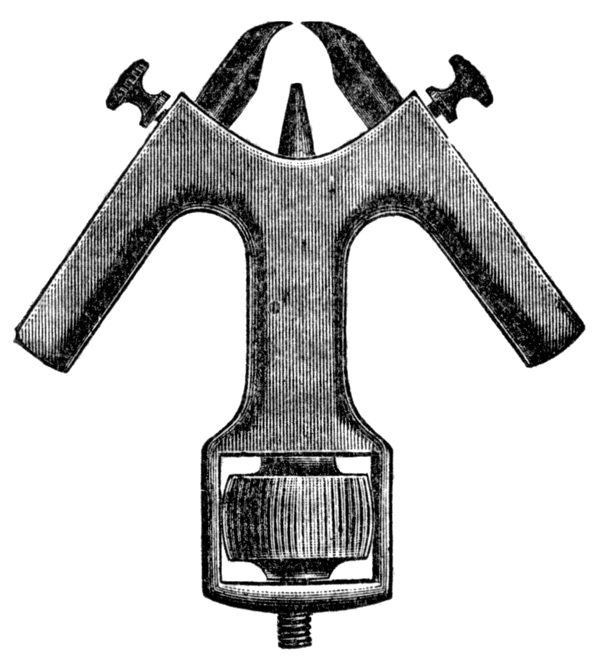
Fig. 126.
303. Roller Remover. There are numerous designs in the way of roller removers upon the market, some of them good but many of them weak and liable to bend where the roller is very tight on the staff. All points being considered, the Hardinge remover, shown in Fig. 126, is perhaps the strongest and best on the market and is built on true mechanical principles.
The nose in the center and top of the illustration is drilled up so as to receive a balance pivot without bearing on its point, and can be moved towards or from the two bent prongs by means of the thumb nut at the bottom of the tool. The prongs can be spread apart or drawn together, and are secured in place by means of the binding screws at the sides. In using the remover the feet of the two prongs are brought under the roller and secured by the binding screws. The nose is now advanced against the shoulder of the bottom pivot and the staff can be driven out without damage to either roller or staff.
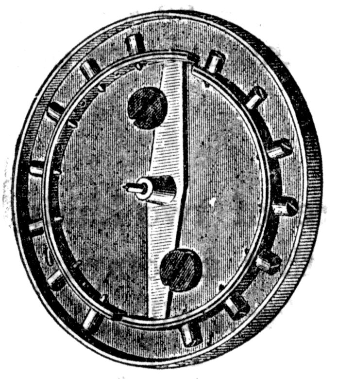
Fig. 127.
304. Balance Protectors. These are of two kinds and for entirely different operations. The Arrick protector, shown in Fig. 127, is used for protecting balances while working upon the pivots while in the lathe. No matter how careful a person may be, accidents will happen, and the least accident to a compensation balance gives the workman considerable trouble. The least slip of the graver, polisher or hand rest and great damage is the result. The staff is passed through the hole in the protector, and held in a wire chuck, and the protector is secured to the arms of the balance by two screws. The Bullock protector, shown in Fig. 128, is designed to protect the balance and other wheels from heat while drawing the temper from staff or pinion for the purpose of pivoting.
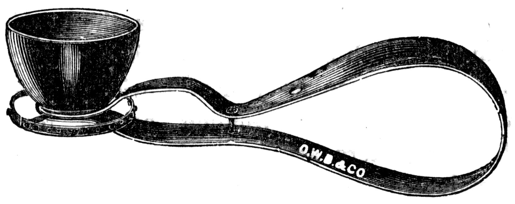
Fig. 128.
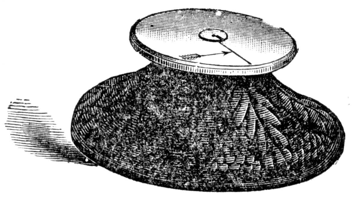
Fig. 129.
305. Beat Block. This simple device obviates the necessity of marking the balance to see that it is in beat. Before taking off the hair spring lay it on the block, shown in Fig. 129, turn the balance so the roller pin hits on the side the arrow points, then turn the table so that the line comes under the stud. In replacing the balance put the stud over the line and it will then beat the same as before. By using this tool you also avoid getting the balance out of true.
306. Female Centers. Centers are of two kinds,, male and female. The ordinary centers that accompany the lathe, which are male centers, are familiar to all watchmakers. Female centers, however, are not so well known among watchmakers, and they can be used to great advantage in many operations where other and less simple attachments and means are usually resorted to. You should have at least six pairs of female centers, the largest being one-fourth of an inch in diameter, which will accommodate as large a piece as you will wish to handle on your watch lathe, viz: winding arbors for clocks. These female centers are made from steel tapers, the same as male centers are made, but instead of turning the end to a sharp point they are countersunk, Fig. 130. First place the taper in a chuck and turn off the outside and end true; drill a small hole in the center of the taper, while the lathe is running, and deep enough so the countersink will not reach the bottom of the hole, or one-eighth of an inch deeper than the countersink. Harden the end only, and after tempering polish off the bluing. After you have made all the sizes you require, test all of them in your lathe to make sure they did not get out of true in tempering.
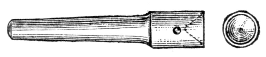
Fig. 130.
These female centers are very useful for holding or suspending any article in the lathe that is too large to be held in the split chucks. Pivots of clocks can be turned and polished very quickly and accurately in these centers.
Almost any kind of large work can be done on a medium sized watchmaker’s lathe by fitting to it a face plate one and three-fourths inches in diameter, with four slots, and fitted to a chuck with a standard taper hole to receive both male and female centers interchangeably. With two styles of dogs, almost any kind of large clock work can be readily handled.
These centers prove very useful for many odd jobs. As an example: It is a very common occurrence to hear an American clock beat irregularly, caused by the escape wheel being out of round. Select a pair of female centers that will admit the ends of the pivots of the escape wheel snugly; place one center in the taper chuck and the other in the tail stock spindle, and suspend the escape pinion in these centers; fasten on a dog, run the lathe at a high speed and hold a fine sharp file so it will touch the teeth of the ’scape wheel slightly, and in a moment the wheel will be perfectly round, after which sharpen up the teeth that are too thick.
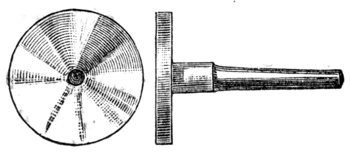
Fig. 131.
307. Drill Rest. In using the lathe for drilling, a great saving in both time and drills can be effected by using a drill rest similar to that shown in Fig. 131. It is well to have a half dozen different sizes, starting at ¼ inch and increasing by ⅛ inch, for various classes of work. These rests are not kept by material dealers, but can be made by the watchmaker. Saw from a piece of rolled sheet brass, say 1-16 inch thick, the circles required, leaving metal enough to finish nicely. Place a steel taper plug in the taper chuck of your lathe and turn down a recess, leaving a shoulder on the taper. Drill a hole through the brass plate to fit the steel taper tightly. Place the end of the taper on a lead block and proceed to rivet the brass plate, on the taper, making sure that it is true replace the taper in the lathe chuck and proceed to turn the face and edge of the brass plate perfectly true and to the proper size. Those who have tried to drill a straight hole through an object by holding it in the fingers know just how difficult it is to do, but by placing one of these drill rests in the spindle of the tail stock, placing the article to be drilled against it and bringing it up against the drill, you can drill the hole perfectly upright and avoid all danger of breaking the drill.
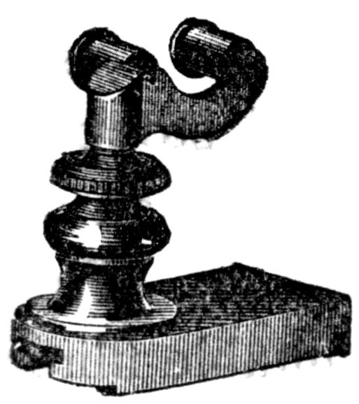
Fig. 132.
308. Filing Fixture or Rest. These rests will be found very convenient in squaring winding arbors, center squares, etc. There are several makes of these tools, but they are all built upon the same principle, that of two hardened steel rollers on which the file rests, and Fig. 132 is a fair example. One pattern is made to fit in the hand rest after the T is removed, while the other is attached to the bed of the lathe in the same manner as the slide rest. The piece to be squared is held in the split or spring chuck in the lathe, and the index on the pulley is used to divide the square correctly. Any article can be filed to a perfect square, hexagon or octagon as may be desired. The arm carrying the rollers can be raised or lowered as required for adjustment to work of various sizes.
309. Filing Block. A contrivance made to take the place of the filing rest, which was made of box wood or bone. Ide’s filing fixture, shown in Fig. 133, consists of a cylinder of hardened steel, riveted upon a staff which in turn enters a split socket. The surface of the steel cylinder is grooved with various sizes of grooves for the different sizes of wire, or to suit any work.
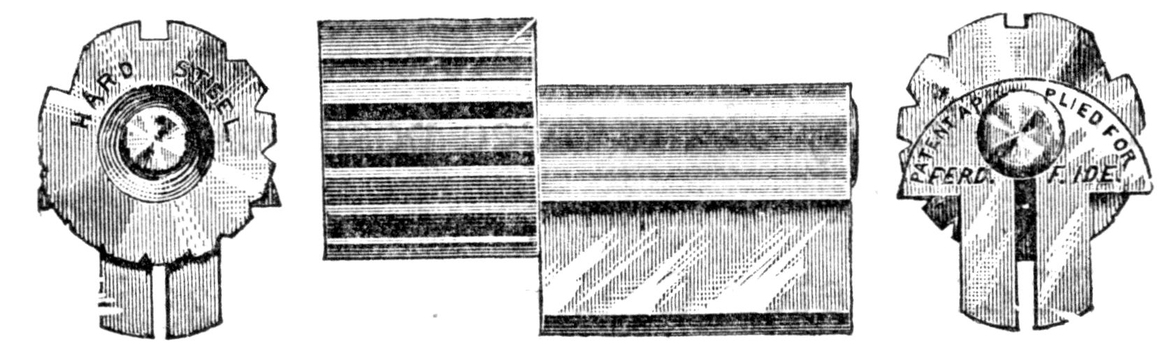
Fig. 133.
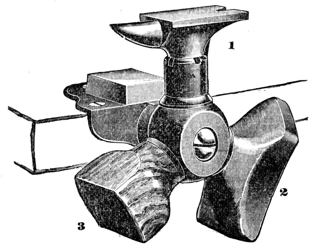
Fig. 134.
Fig. 134 illustrates Melotte’s revolving bench block, which combines both anvil and filing block. No. 1 is a steel anvil which may be instantly revolved and stopped on quarters. No. 2 is a rubber block, held by friction on its arm, and can readily be turned to any position. This rubber, being slightly elastic, makes a very suitable filing bed for small articles of any material and may be used without risk of scratching or defacing polished surfaces. No. 3 is a wooden block, held on to its arm by a spring friction device, which also allows it to be turned around to any desired position. The three-armed hub is revolved by pulling out slightly and is automatically held perfectly firm and solid in any of the three positions.
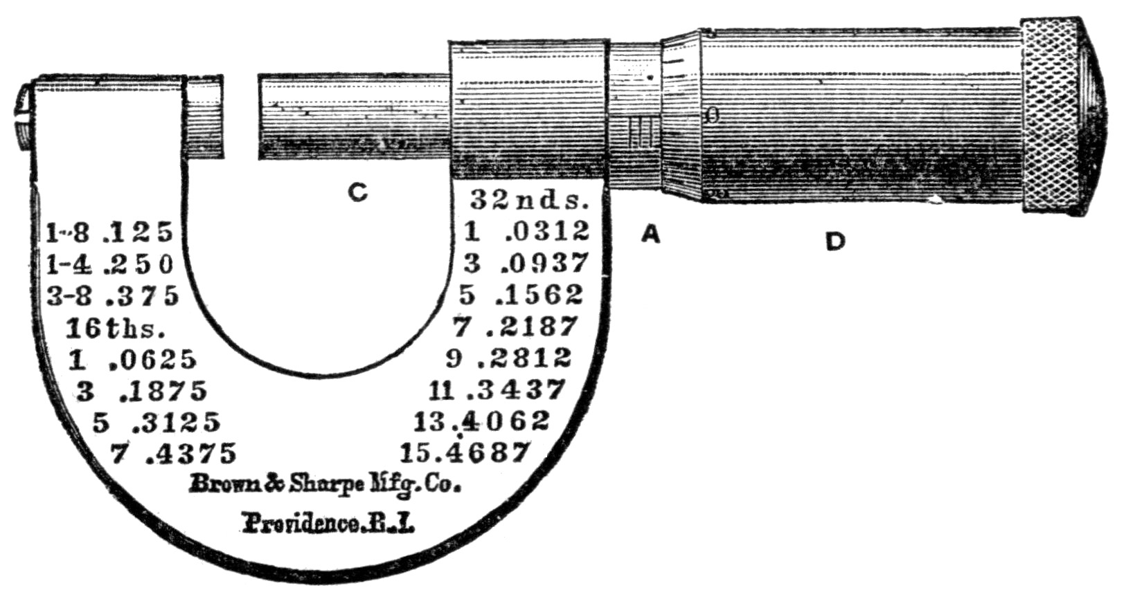
Fig. 135.
310. Micrometer Caliper. Fig. 135 is a full size cut of the Brown & Sharp Mfg. Co.’s micrometer caliper. It measures from one-thousandth of an inch to one-half inch. It is graduated to read to thousandths of an inch, but one-half and one-quarter thousandths are readily estimated. This instrument is also graduated to the hundredths of a millimeter, but when so graduated the table of decimal equivalents is omitted. They are also made to read to ten thousandths of an inch. The edges of the measuring surfaces are not beveled, but are left square, as it is more convenient for measuring certain classes of work. It will gauge under a shoulder or measure a small projection on a plain surface. Watchmakers will especially appreciate micrometers of this form. This tool will be found very useful for gauging mainsprings, pinions, etc. In the caliper, shown by cut, the gauge or measuring screw is cut on the concealed part of the spindle C, and moves in the thread tapped in the hub A; the hollow sleeve, or thimble D is attached to the spindle C and covers and protects the gauge screw. By turning the thimble, the screw is drawn back and the caliper opened.
The pitch of the screw is 40 to the inch. The graduation of the hub A, in a line parallel to the axis of the screw, is 40 to the inch, and is figured 0, 1, 2, etc., every fourth division. As the graduation conforms to the pitch of the screw, each division equals the longitudinal distance traversed by the screw in one complete rotation, and shows that the caliper has been opened 1-40th or .025 of an inch. The beveled edge of the thimble D is graduated into 25 equal parts, and figured every fifth division 0, 5, 10, 15, 20. Each division when passing the line of graduation on hub A, indicates that the screw has made 1-25th of a turn, and the opening of the caliper increased 1-25th of 1-40th, or a thousandth of an inch.
Hence, to read the caliper, multiply the number of divisions visible on the scale of the hub by 25, and add the number of divisions on the scale of the thimble, from zero to the line coincident with the line of graduation on hub. For example: As the caliper is set in the cut, there are three whole divisions visible on the hub. Multiply this number by 25, and add the number of divisions registered on the scale of the thimble, which is 0 in this case, the result is seventy-five thousandths of an inch. (3 × 25 = 75 0 = 75). These calculations are readily made mentally.
Differences between Wire Gauges in Decimal Parts of an Inch.
No. of Wire Gauge. American or Brown & Sharpe. Birmingham or Stubs’. Washburn & Moen Manufacturing Co., Worcester, Mass. Trenton Iron Co., Trenton, N.J. New British. Old English from Brass Mfrs. List. No. of Wire.
000000 —— —— .46 —— —— —— 000000
00000 —— —— .43 .45 —— —— 00000
0000 .46 .454 .393 .4 .4 —— 0000
000 .40964 .425 .362 .36 .372 —— 000
00 .3648 .38 .331 .33 .348 —— 00
0 .32495 .34 .307 .305 .324 —— 0
1 .2893 .3 .283 .285 .3 —— 1
2 .25763 .284 .263 .265 .276 —— 2
3 .22942 .259 .244 .245 .252 —— 3
4 .20431 .238 .225 .225 .232 —— 4
5 .18194 .22 .207 .205 .212 —— 5
6 .16202 .203 .192 .19 .192 —— 6
7 .14428 .18 .177 .175 .176 —— 7
8 .12849 .165 .162 .16 .16 —— 8
9 .11443 .148 .148 .145 .144 —— 9
10 .10189 .134 .135 .13 .128 —— 10
11 .090742 .12 .12 .1175 .116 —— 11
12 .080808 .109 .105 .105 .104 —— 12
13 .071961 .095 .092 .0925 .092 —— 13
14 .064084 .083 .08 .08 .08 .083 14
15 .057068 .072 .072 .07 .072 .072 15
16 .05082 .065 .063 .061 .064 .065 16
17 .045257 .058 .054 .0525 .056 .058 17
18 .040803 .049 .047 .045 .048 .049 18
19 .03539 .042 .041 .039 .04 .04 19
20 .031961 .035 .035 .034 .036 .035 20
21 .028462 .032 .032 .03 .032 .0315 21
22 .025347 .028 .028 .27 .028 .0295 22
23 .022571 .025 .025 .024 .024 .027 23
24 .0201 .022 .023 .0215 .022 .025 24
25 .0179 .02 .02 .019 .02 .023 25
26 .01594 .018 .018 .018 .018 .0205 26
27 .014195 .016 .017 .017 .0164 .01875 27
28 .012641 .014 .016 .016 .0148 .0165 28
29 .011257 .013 .015 .015 .0136 .0155 29
30 .010025 .012 .014 .014 .0124 .01375 30
31 .008928 .01 .0135 .013 .0116 .01225 31
32 .00795 .009 .013 .012 .0108 .01125 32
33 .00708 .008 .011 .011 .01 .01025 33
34 .006304 .007 .01 .01 .0092 .0095 34
35 .005614 .005 .0095 .009 .0084 .009 35
36 .005 .004 .009 .008 .0076 .0075 36
37 .004453 —— .0085 .00725 .0068 .0065 37
38 .003965 —— .008 .0065 .006 .00575 38
39 .003531 —— .0075 .00575 .0052 .005 39
40 .003144 —— .007 .005 .0048 .0045 40
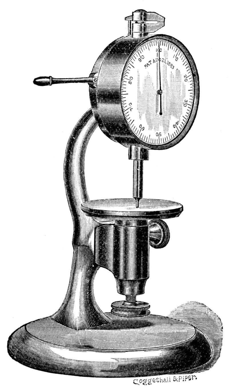
Fig. 136.
311. Registering Gauge. The registering gauges shown in the illustrations are two of the best examples of this class of tools. They are manufactured by A. J. Logan, Waltham, Mass., and are very accurate and nicely finished. Fig. 136 is an upright and jaw gauge, and Fig. 137 is designed as a jaw and depth gauge. They are both made to gauge one-thousandth of a centimeter or one-thousandth of an inch. Fig. 137 shows the piece of work marked A being gauged, while B represents a sliding spindle to get the depth of a hole or recess, or the thickness of any piece of work, which will be indicated on the dial.
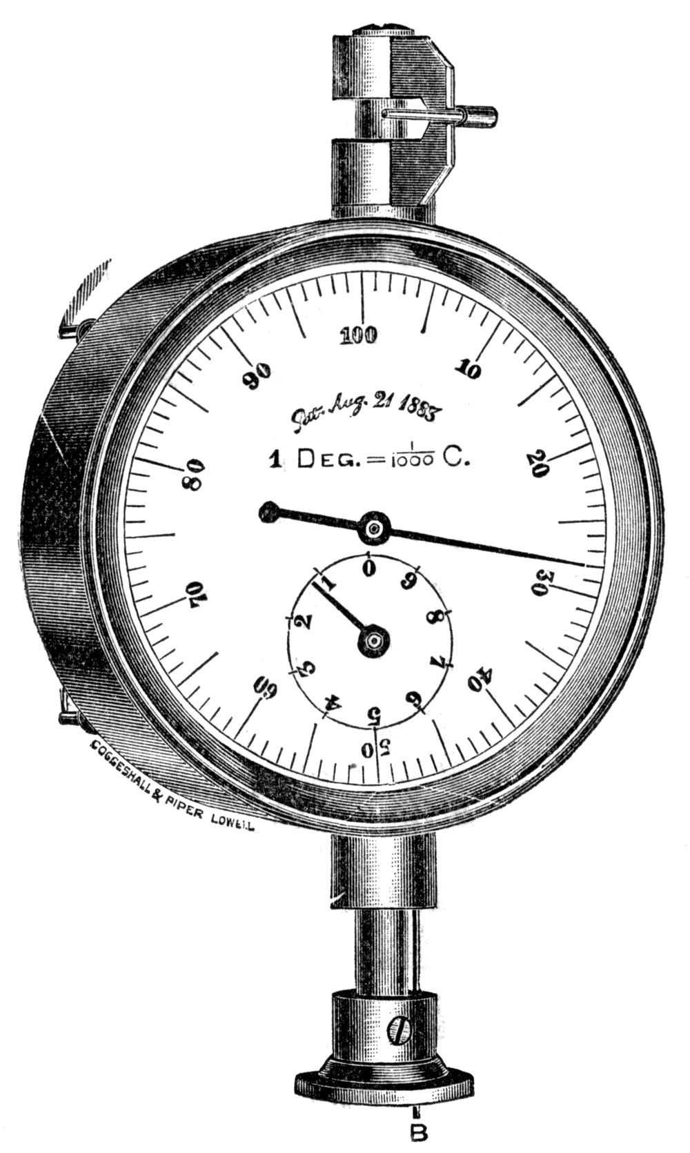
Fig. 137.
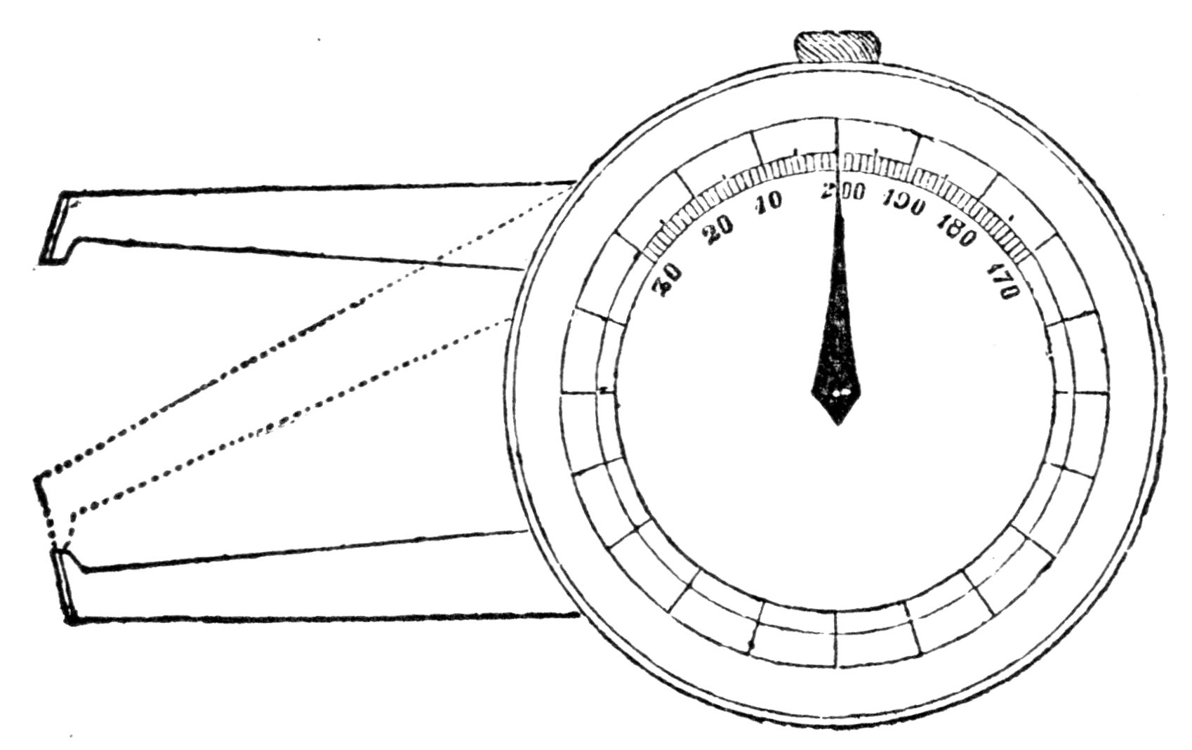
Fig. 138.
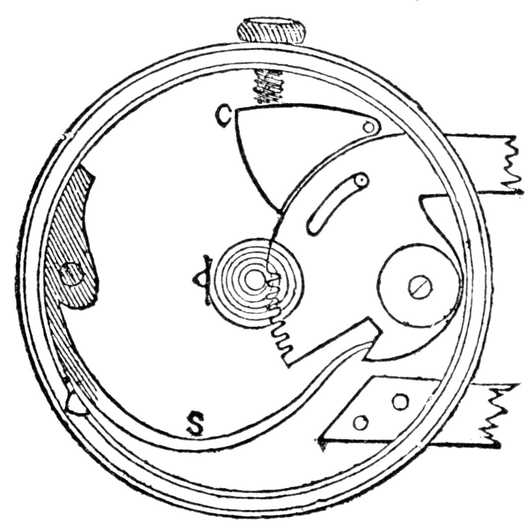
Fig. 139.
Another form of registering gauge is shown in Fig. 138. It is an English gauge and but little used in this country. The principle of its construction, however, is good, and any ingenious watchmaker can make it. The back of the dial is recessed and arranged as in Fig. 139. One limb is fixed; the other is pivoted, and has a few rack teeth meshing into a center pinion. The pinion carries the hand, which should make a revolution in closing the calipers. The spiral spring attached to the pinion is to keep it and the hand banked in one direction for shake. The spring s is to keep the jaws open. The milled headed screw and the clamp c are to fix the jaws in case it is required to do so. A cover is snapped into the recess, and takes the back pivot of the pinion.
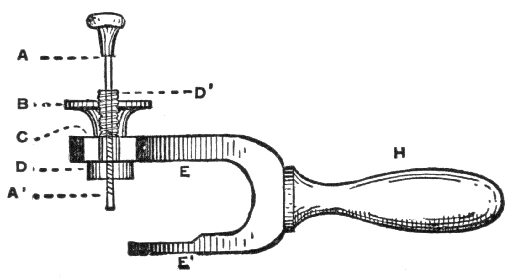
Fig. 140.
312. Staff Gauge. The tool shown in Fig. 140 is designed for measuring the height of the balance staff from the balance seat to the end of the top pivot. The illustration is enlarged to give more distinctness. E E′ is a piece of curved steel about ¹⁄₂₀ of an inch thick, and ¹⁄₂₅ of an inch wide. On the lower side from E′ to the end, the arm is filed down in width and thickness to correspond to an ordinary balance arm; C is a slot in the upper arm E, which allows A, B, D, A′ to be moved backward and forward. D D′ is a round brass post drilled and tapped. The part D′ has a thread cut on it, and the part shown in the slot C fits with easy friction. B is a lock-nut, drilled and tapped to fit the thread on D′. It is for the purpose of clamping D D′ against the arm E. A A′ is a small steel screw with milled head, and is made to fit the tapped hole in D D′.
Mr. Beeton describes his method of using this tool as follows: Take your measurement of the distance the balance seat is to be from the end of the top pivot, as follows: remove the end-stone in balance-cock, and screw the cock on the top of the top plate (18-size full plate movement); then taking the plate in your left-hand, and tool (shown in Fig. 139) in your right, place H in position, so that the end of the screw A′ rests on the jewel in the balance cock, and notice the position of the arm E′ which corresponds to the balance arm, between the top plate and under side of the balance-cock. If the distance between the arm E′ and end of screw A′ is too great, the arm E′ will be too low and touch the plate; if not enough, it will be too high and touch the regulator pins. Therefore, all that is necessary to do is to move the screw A A′ up or down as the case may be, sufficiently to ensure that the arm E′ will assume the position the arm of the balance is to have. Take an 18-size balance with oversprung hairspring, the arm is at the bottom of the rim; in that case, when measuring, the screw A′ is adjusted so as to bring the arm E′ close to the plate, when A′ is resting on the balance jewel; if the balance is old style with undersprung hairspring, the balance arm is at top of rim, in which case A′ is adjusted so that the arm E′ is close to the balance cock; if the balance arm is in the center of the rim, as in some English and Swiss balances, the screw A′ is adjusted so that the arm E′ is midway between the plate and cock.
The reason the part A, B, D, A′ are arranged to move laterally in slot C is, because all balance shoulders are not the same distance from the center, and where, in some cases, the screw A′ would be in a line with the center of the staff when the arm E′ was resting on the balance seat, in other cases it would reach past the center, of course, short of it; and, therefore, it is made adjustable to suit all cases.
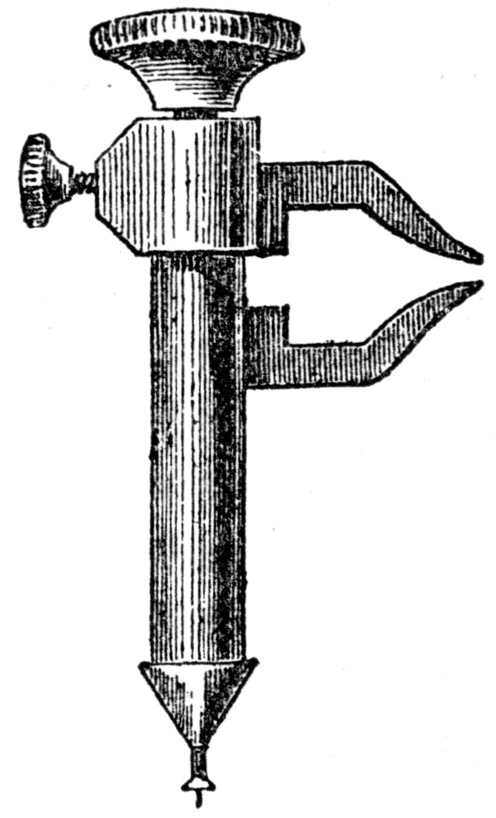
Fig. 141.
313. Staff or Cylinder Height Gauge. The obvious advantage of this tool, which is shown at Fig. 141, is the automatic transfer of the measurement so that it may be readily applied to the work in hand. The tool, as the illustration shows, consists of a brass tube terminating in a cone-shaped piece. To the bottom of this cone is attached a disc through which a needle plays. Around the upper end of the tube is a collar upon which is fixed a curved steel index finger. A similar jaw, which is free to move, works in a slot in the tube. The movable jaw is tapped and is propelled by a screw that terminates in the needle point. This tool is very useful in making the necessary measurements required in putting in a staff. To use it in this work, set the pivots of the gauge through the foot hole, and upon the end-stone project the needle such a distance as you wish the shoulder to be formed above the point of the pivot. Next set the gauge in the foot hole as before, and elevate the disc to a height that shall be right for the roller, which is done by having the lever in place, the little disc showing exactly where the roller should come. Finish the staff up to that point; then take the next measurement from the end-stone to where the shoulder should be, for the balance to rest upon. This point being marked, the staff can be reversed and measurements commenced from the upper end-stone, by which to finish the upper end of the staff. Distances between the shoulders for pinions and arbors can be obtained with the same facility, a little practice being the only requisite.
314. Vernier Caliper. Fig. 142 is an illustration of the Vernier Caliper, a light, convenient and valuable instrument for obtaining correct measurements. The side represented in the illustration is graduated upon the bar to inches and fiftieths of an inch, and by the aid of a Vernier is read to the thousandths of an inch (see description below). The opposite side is graduated to inches and sixty-fourths of an inch. The outside of the jaws are of suitable form for taking inside measurements, and when the jaws are closed, measure two hundred and fifty thousandths of an inch in diameter.
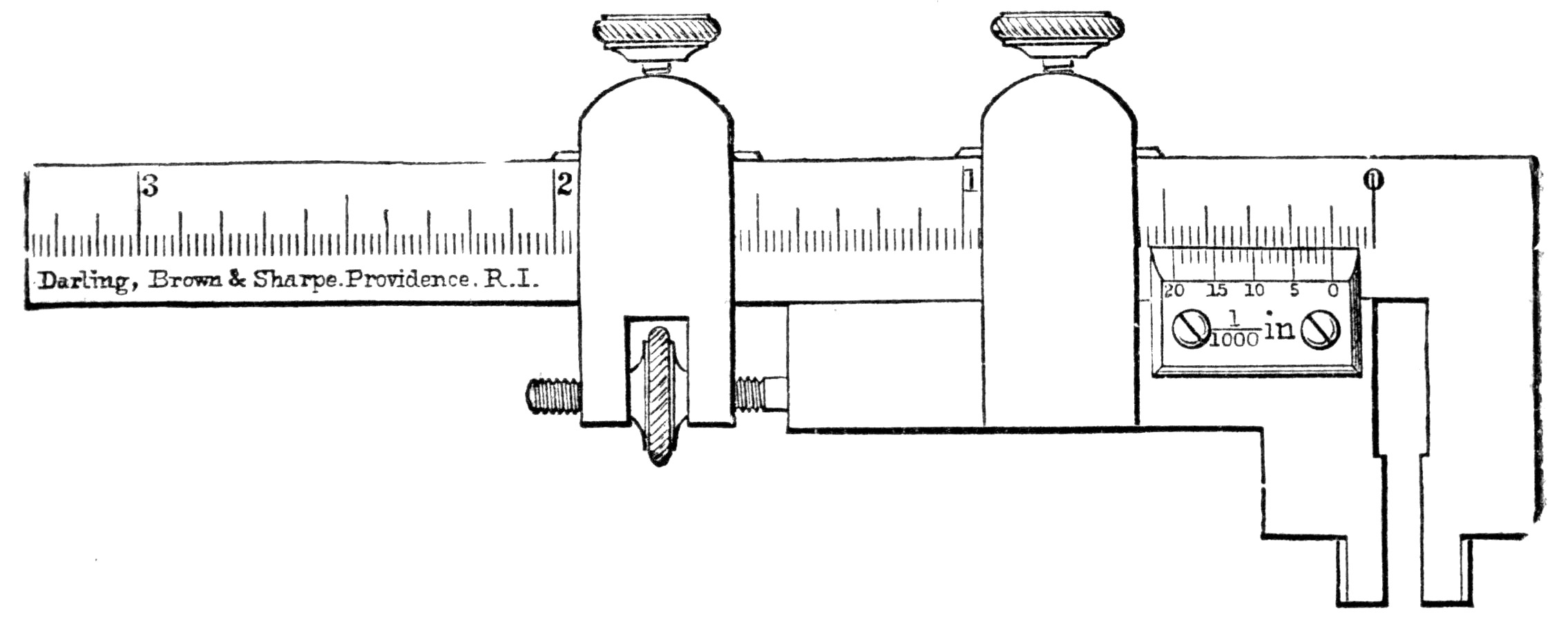
Fig. 142.
These instruments can be furnished with millimeters (in the place of sixty-fourths of an inch), and provided with a Vernier to read to one-fiftieth of a millimeter.
On the bar of the instrument is a line of inches numbered 1, 2, 3, each inch being divided into tenths, and each tenth into five parts, making fifty divisions to one inch. Upon the sliding jaw is a line of divisions (called a Vernier, from the inventor’s name), of twenty parts, figured 0, 5, 10, 15, 20. These twenty divisions on the Vernier correspond to extreme length with nineteen parts, or nineteen-fiftieths on the bar, consequently each division on the Vernier is smaller than each division on the bar by one-thousandth of an inch. If the sliding jaw of the caliper is pushed up to the other, so that the line 0 on the Vernier corresponds with 0 on the bar, then the next two lines on the left will differ from each other one-thousandth of an inch, and so the difference will continue to increase one-thousandth of an inch for each division till they again correspond on the twentieth line on the Vernier. To read the distance the caliper may be open, commence by noticing how many inches, tenths and parts of tenths the zero point on the Vernier has been moved from the zero point on the bar. Then count upon the Vernier the number of divisions until one is found which coincides with one on the bar, which will be the number of thousandths to be added to the distance read off on the bar. The best way of expressing the value of the divisions on the bar is to call the tenths one hundred thousandths (.100) and the fifths of tenths, or fiftieths, twenty thousands (.020). Referring to the accompanying cut, it will be seen that the jaws are open one-tenth of an inch, which is equal to one hundred thousandths (.100). Suppose now, the sliding jaw was moved to the left, so that the first line on the Vernier would coincide with the next line on the bar, this would then make twenty thousandths (.020) more to be added to one hundred thousandths (.100), making the jaws then open one hundred and twenty thousandths (.120) of an inch. If but half the last described movement was made, the tenth line on the Vernier would coincide with a line on the bar, and would then read, one hundred and ten thousandths (.110) of an inch.
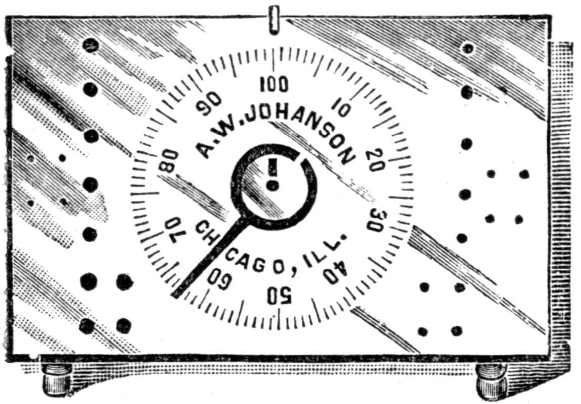
Fig. 143.
315. Hair Spring Stud Index. Fig. 143 illustrates Johanson’s hair spring stud index. The engraving shows the full size of the tool, which consists of a steel plate mounted on feet, and pierced with a number of holes for the reception of screws, when taking down a watch. In the center of the index is a hole for the staff, and an oblong slot for the reception of the roller jewel. To get any American movement in beat, proceed as follows: In front of No. 100 is a small spring; push same towards No. 10; then place the balance on top of the stand, with staff in center and roller jewel in the oblong hole; let the spring back gently; the balance will then take its own position. Set degree hand in front of the desired degree, as per direction on index table; place hair spring stud in front of degree hand, and push on the collet.
INDEX TABLE FOR HAIR SPRING STUDS.
Size. Degree.
Columbus 18 Open Face Breguet 23
Columbus 6 Open Face Breguet
Elgin 18 Open Face Breguet 66
Elgin 16 Open Face Breguet 52
Elgin 16 Flat Hair Spring 52
Elgin 10 Flat Hair Spring 50
Elgin 6 and 8 Flat Hair Spring 50
Elgin 0 Flat Hair Spring
Illinois 18 Open Face Breguet 33
Illinois 18 Hunting 84
Illinois 18 Open Face Flat 89
Illinois 16
Illinois 6 Hunting 52
Illinois 4
Hampden 18 Dueber Hunting 80
Hampden 18 Open Face 75
Hampden 16
Hampden 6 Hunting 50
Howard 18 Old Model 5
Howard 18 New Model 23
Howard 16
Howard 6
Rockford 18 27
Rockford 6
Waltham 18 Key Flat Hair Spr’g 48
Waltham 18 O. F. Hair Spring 61
Waltham 18 Breguet 50
Waltham 14-16 42
Waltham 4-6 50
Waltham 1 42
Seth Thomas 18 Open Face 50
Seth Thomas 18 Hunting 52
316. Oil-cup Drills or Chamfering Tools. The reservoirs that contain a supply of oil at the ends of pivot holes are made in the lathe with a semi-cylindrical drill, or by hand with a chamfering tool of the form shown at B or C, Fig. 144. A drill gives a clean cut, but necessitates a subsequent polishing of the hole; as to the chamfering tool here referred to, some inconvenience will be experienced in its use, owing to the point being apt to jump out of the hole and make irregular scratches on the brass, which are difficult to remove.
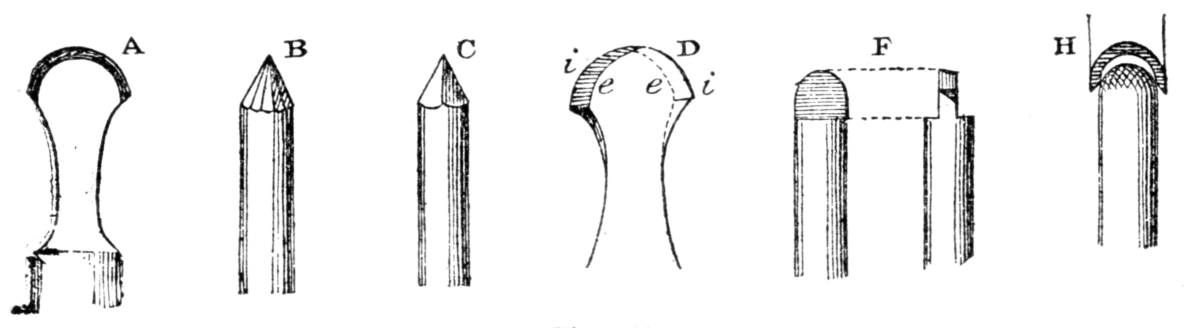
Fig. 144.
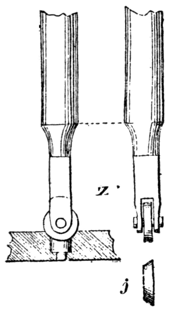
Fig. 145.
The best shapes of drills for making, or at any rate for re-forming or finishing oil-cups, are shown at D and F, Fig. 144, and in Fig. 145.
D and F are two drill-blades that terminate in non-cutting circular arcs. The flat curved end is more and more inclined from the top towards the corner, from i towards the side e; the angle at i becoming more acute, and at e more obtuse towards the corners. The drill will, of course, only cut when rotating in one direction; in the other direction the obtuse angles and the reverse sides of the cutting angles will act as burnishers. Thus if the angles on either side are well formed and the blade has been polished, the surface of the oil-cup will be clean cut and polished. F is similar to D, but made from a steel rod.
317. Observations on making the oil-cups. Reservoirs that are made with a drill, or with a chamfering tool by hand, will often be found to be eccentric, and, when a pivot-hole is bushed and re-drilled, it proves to be struck from a different center from the oil-cup. In such cases watchmakers often give themselves endless trouble without securing a cup of good form and well centered. This difficulty can be avoided by using the tool in a lathe driven by a wheel; then, holding the plate in one hand square against a drill rest in tail stock, advance the tail stock with the other hand so as to bring the plate in contact with the drill.
When it is only required to correct the form of an oil-cup, the drill may be replaced by a rod with file cuts on its rounded extremity (H, Fig. 144). The reader will find no difficulty in making such a cutter for himself, drawing a file with both hands over the rounded end, but always in the direction of the file-cuts. After covering the surface with lines in this manner, rotate the cutter through a right angle and form a number of cross cuts. Or roughen the surface with a chisel of the form shown at H; after making a few cuts parallel to each other, turn the chisel through an angle and repeat the operation.
318. Chamfering Tool. As is well known, this is used for removing the roughness that a drill leaves at the edge of a hole, or to take off the cutting edge around a screw head sink, etc., thus forming a bevel edge. The tool commonly has a flat semicircular blade, the diameter of which depends on size of hole to be made; this semicircle is ground to a cutting edge like a drill, as shown at A, Fig. 144. Chamfering tools are also made pyramidal, with flat faces, as at B and C; the angle at the apex is more or less acute, according to the depth of chamfer required.
The oil-cup drills D and F are also used for chamfering the edge of a hole.
A cone formed at the extremity of a piece of pinion wire with a cutting edge on each leaf and hardened will be found very useful for this purpose.
319. The two forms of chamfering tool first described leave a series of undulations on the bevel edge, so that, instead of being conical, it presents a number of small facets. This inconvenience can be avoided by using the tool shown at Z, Fig. 145.
A small disc of hardened steel is pivoted within a recess formed at the end of a rod, the pin on which it rotates being at right angles to the direction of the rod. As is seen in the figure to right of Z, the section of this roller is a rectangle, and the surface is carefully polished, the edges being left sharp.
Clockmakers make use of a tool for forming oil-cups that only differs from the one above described in two particulars: (1) The disc is fixed on its axis; and (2) the edge, instead of being square to the two faces, is inclined as shown at j and at the same time is slightly rounded crosswise.
A few trials will be found necessary before the most convenient thickness and inclination of edge are arrived at.
320. Hollow Chamfering Tools. These, as is well known, are used for removing the angles at the ends of cylindrical rods, of steady-pins, etc., or for rounding them off. Three forms are shown at O, Q, N, Fig. 146.
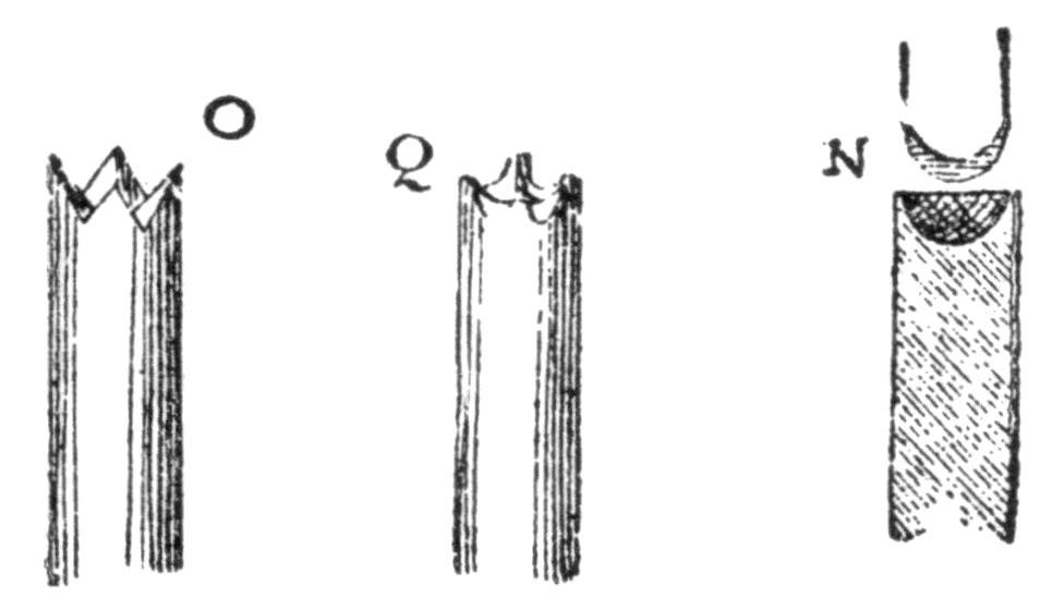
Fig. 146.
O is a round rod, the flat end of which has been filed across with the corner of a triangular file. Four cutting edges are thus produced which will act on the end of any object that rotates within them, or vice versa. If it be required to form a very acute angle, two slits must be cut with a screw-head file and the sides afterwards inclined to the required extent with a flat file. This tool will serve a double purpose: (1) to chamfer off the edge of a rod; and, (2) by prolonging this operation to form a point at the end.
As a rule, when it is desired to round off, say, a pillar of a clock after reducing its length or from any other cause, a hollow chamfering tool of very open angle is used, a rocking motion being imparted to it round the axis of the spindle; it is better to use a tool of the shape shown at N or Q. The latter, Q, is easily formed by strokes of a rat-tail file at right angles across its end; the other, N, is cut internally with a shaped chisel or with a small rotating cutter to which different inclinations are given during the cutting, as is also done when using the chisel.
321. The tool shown at O, Fig. 146, has been modified as follows by M. Roze. The two notches at right angles are replaced by three equidistant notches of equal depth. To make these in a piece of round steel it should be divided on the circumference into six equal parts; then cut the three notches as follows: Calling the points marked on the circumference 1, 2, 3, 4, 5, 6, one notch will lie parallel to the line joining 1, 3, and equidistant between this line and the point 5; a second will be parallel to 3, 5, and midway between that line and point 1, and the third will be parallel to 5, 1, and midway between this and the point 3.
In a hollow chamfering tool thus constructed it will be found that only the three long sides 1, 3, 5, actually cut, and at 2, 4 and 6 are short sides that are set back. But when a file is laid on the face joining two of the former sides, say 1, 3, the short faces 4, 6, will protect the cutting edge 5 from contact with the file.
322. Tool for Centering Rods. These appliances are well known to watchmakers, who often employ them for marking the position of the hole in the brass wire when making bushings. It is advisable to have such a tool somewhat large, about a third as large again as that shown at s r, Fig. 147.
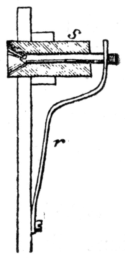
Fig. 147.
The head of the centering punch or drill is filed flat on either side, and this flattened portion passes into a notch in the spring r, which maintains it in position and prevents rotation when the triangular-pointed blade is pressed against the end of this rod, this rod being caused to rotate in the hollow cone of s. Instead of a spring such as r, a helical spring is often used; but it then becomes necessary to fix a pin in the drill that slides in a groove in s, so as to prevent the drill from rotating.
323. Centering with a Set-Square. The set square may be used for centering round rods, and the following is a very simple mode of applying it:
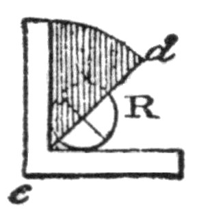
Fig. 148.
On one arm of the square R, Fig. 148, a triangular plate c d is screwed or riveted so that its edge c d exactly bisects the right angle, that is, divides it into two equal angles. The flat end of a round rod is held within the angle and against the plate, a line being traced on it along c d; it is then turned through about a right angle and a second line traced. The intersection of these two lines gives the axis of the rod.
324. Tool for Roughing Out Points. This is merely the inverted chamfering tool of which two forms are described in paragraphs 320-21, one of them being also shown at O, Fig. 146. It will be evident that when the end of a rod is caused to rotate in this hollow cone it will take its form.
In some cases it may be found convenient to place such a tool in the tail stock of the lathe.
If the bottom of the cone at the end of O were prolonged by continuing the cuts farther down with a thin flat file, the point of the rod might be formed like a conical-headed screw before it is tapped.
325. Balance-spring Collet Tool. This convenient little tool for rotating the balance-spring collet is commended almost as much by its simplicity and facility of construction as by its usefulness.
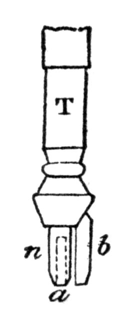
Fig. 149.
A steel rod n, Fig. 149, is fixed in a handle T; it terminates in a cone a and is drilled with a fine hole as indicated by the dotted lines. A thin wing b, pointed at its extremity, is also attached to the handle.
Holding the balance between the fingers of the left hand and the tool in the right, the blade b is introduced into the slit in the collet while a rests on the balance staff shoulder, the pivot being within the hole n. Now rotate to the right or left until the stud is opposite to the mark on the balance rim, and this may be done without danger, providing the tool is held firmly and vertical.
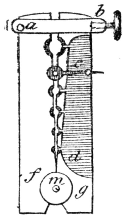
Fig. 150.
326. Watch-hand Holder. A very convenient form of tool, in which to clamp a hand while enlarging the center hole is represented in Fig. 150. Two brass plates, f and g, are hinged at m like a sector. A collar, a b, surrounding the two is pivoted at a and has a clamping-screw b by which the two plates can be forced together. Several circular sinks of different sizes and equally divided between the two plates, are cut of a depth varying from one-half to two-thirds that of the plates, and they must be made to increase in diameter as they get deeper, thus resembling the internal groove that receives a barrel cover. The plate a is cut away along the portion c d and grooves are formed to leave passages open between this surface and the bottom of the sinks in g and f.
When it is required to enlarge the hole of a watch-hand, place it, inverted, in the hole of suitable size, as shown at c of the figure, and tighten the screw b. Held round the whole or greater part of its circumference, the hand is thus firm and its center hole can be enlarged without risk, either with a drill or broach; the hand will not show marks due to the pressure with which it has been held.
327. Common Hand fitting Pliers. The sliding tongs with large flat head, perforated with a number of holes in which the head of a hand is clamped when the opening requires to be enlarged, are often useful, but we feel them to be less so than the holder just described. It is desirable that the inner faces of their jaws, which are usually left rough, be at least smoothed.
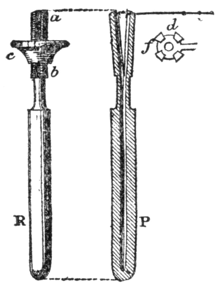
Fig. 151.
328. Another form of Watch-hand Holder. M. Fiquemont has devised the simple little tool shown in Fig. 151. It consists of a short brass rod R, perforated lengthwise and having a thread cut externally on the surface a b. It should be reduced in thickness below this tapped portion. The rod, shown also in longitudinal section at P, is cut into four quarters by two slits from a to b, which are at right angles and leave the points as indicated apart at d. The elasticity of these four quarters should make them take the form of a reversed cone when holding a hand, so that the ascent of the screw c shall tighten them.
Within the head a of the tool is formed a circular recess, so that, if the reversed head of a watch-hand be placed within it and the screw made to ascend, it will be held very firmly by the circumference, as seen in the figure. The hand will thus be perfectly free to adjust in any way that is needed for fitting it while held at the end of the tool, and without being removed before the work is complete. Three or four sizes will suffice for all ordinary watch-hands.
A tool may be made in a similar manner, except that the screw is not divided by the longitudinal slits, and the hand is held against the point by a lantern (similar to those of a screw-point tool), which must be cut away in the manner indicated in Fig. 150, explained above (326). An assortment of three or four lanterns will render the tool serviceable for all sizes of hands.
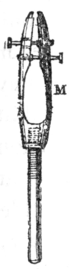
Fig. 152.
329. Clip for Holding Escapewheels while Cleaning. A mere inspection of M, Fig. 152, will make the arrangement of this little tool evident. The fork is made of a piece of brass rod and its two arms are elastic, a handle being screwed into the lower extremity.
Two small steel jaws are fixed to the upper ends inclined towards each other, and, in using the tool, it is only necessary to press with two fingers on the heads of the screws, when the jaws will open. Having placed the escape wheel pinion between them, the wheel will be firmly held so that its teeth can be easily cleaned, etc.
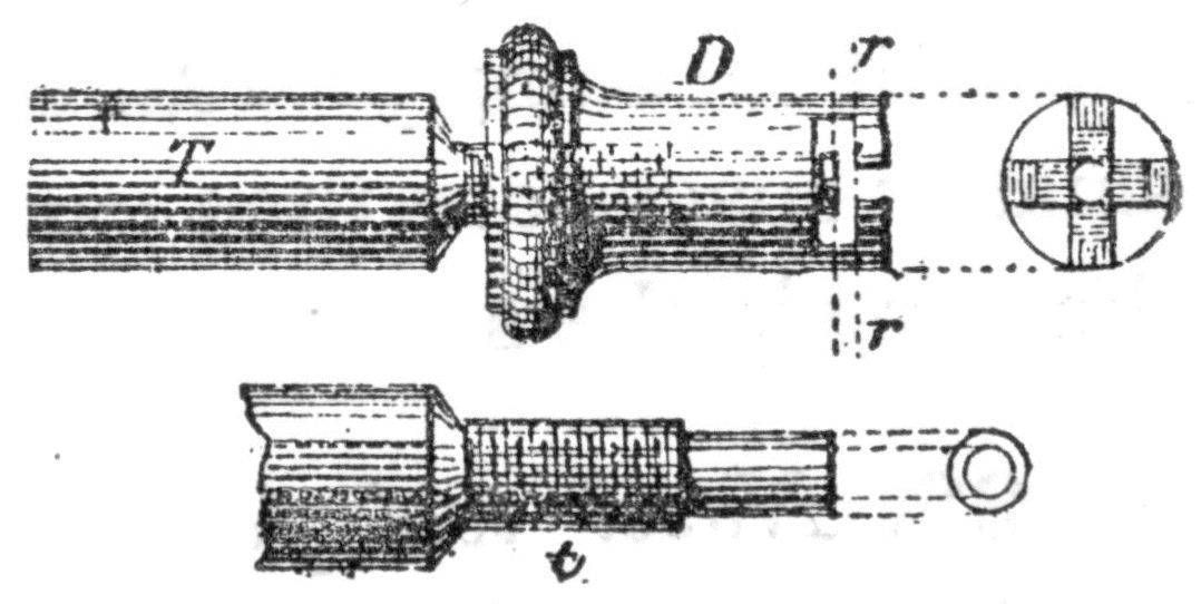
Fig. 153.
330. The appliance shown in Fig. 153 can be used for a similar purpose, and is further especially serviceable for holding an escape-wheel that is not riveted to its pinion. It consists of two parts, a handle T, shown separate at t, which is drilled throughout its length and tapped externally at the portion t, and a collar or nut D, the end of which is traversed by two cuts at right angles that resemble the letter T in section. If the tool is intended for holding escape-wheels that have three instead of four arms, this cross must be replaced by three radiating grooves of similar section. The position occupied by the wheel is indicated by the dotted lines r r, and it will be evident that, when the flat end of T is screwed up against this wheel, after dropping it into the cross and slightly turning round the axis as in a bayonet joint, it may be firmly held. The safest mode of introducing the wheel is by holding it on a broach, which is subsequently removed.
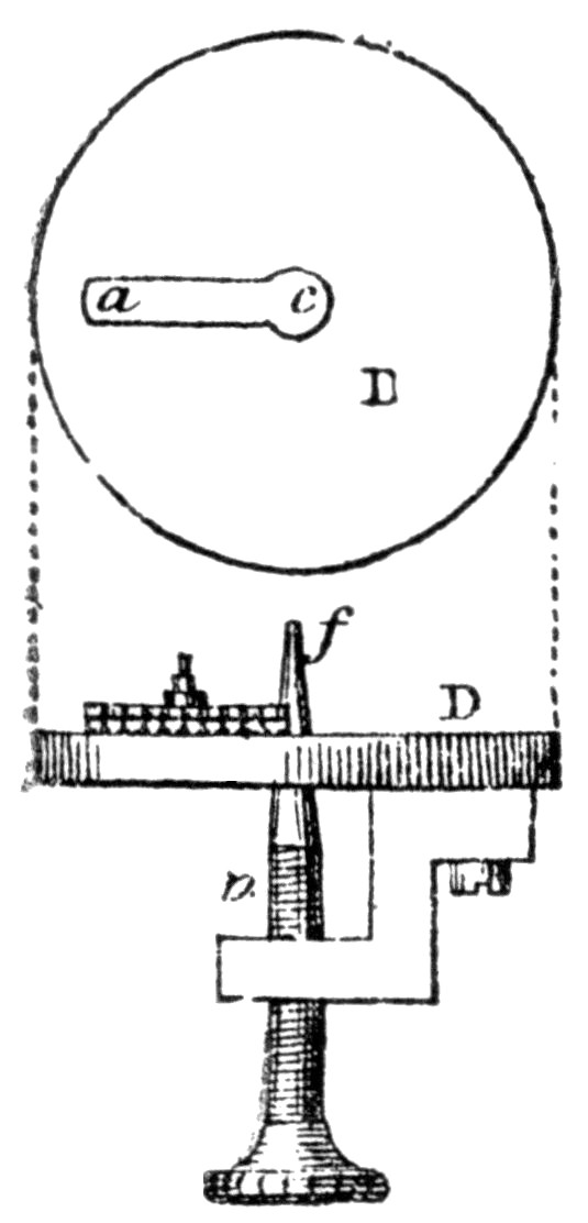
Fig. 154.
331. Tool for Testing the Truth of a Cylinder Escapewheel. The small tool shown at D, Fig. 154, can be advantageously used in place of the plain arbor commonly employed for testing the equality of the spaces in such a wheel. The plate D, which may be mounted on three feet, is traversed at its center by the smooth conical portion f of the screw f v, tapped somewhat tightly into a cock fixed to the other side of the plate. There is a radial slot, a c, cut in the plate large enough to allow an escape-wheel pinion to move freely. An inspection of the figure will make evident the manner in which the tool is to be used: a wheel being placed as shown, or with reverse side upwards, is made to slide towards the center, gradually raising the screw until the largest space is found to admit f with contact at both sides. All the smaller spaces are then carefully opened until they admit the cone in the same manner as the largest.
332. Novel tool for the same purpose. When the spaces are adjusted in the manner explained above, or if the length of the teeth is measured in a narrow gauge plate, there will nearly always remain a certain degree of irregularity in the teeth. A more efficient means would be for the gauge to embrace both a tooth and space, and this condition is satisfied by the following appliance.
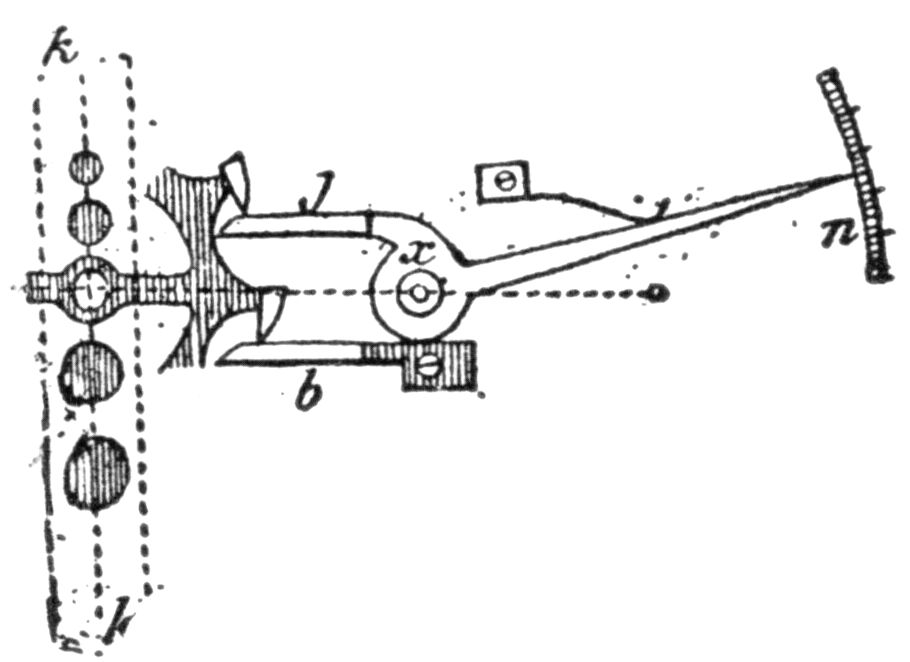
Fig. 155.
The slide k k, Fig. 155, is dovetailed into a plate, level with its surface, so that k k can be moved in a vertical direction by a screw; it is perforated with a series of holes of gradually decreasing diameter. To the same plate are also fixed: (1) a smooth tongue, b, with a foot and screw; and (2) a second tongue, j, terminating in an index x n, which is movable about a pivot, x, and held against a pin in the plate by a light straight or spiral spring. The extremity, n, traverses a graduated arc.
Having introduced the pinion of the wheel, or the arbor on which it is held, into a hole of the slide that it fits without shake, and brought this hole to the position indicated in the figure, apply a slight pressure to the wheel in the direction of its rotation. With one tooth resting against b the tongue j will be held by the spring against the next and the reading of the index is to be noted accurately. Withdraw the wheel slightly, and, placing the succeeding tooth against b, take a second reading, and so on around the entire circumference.
Of course, the delicacy of the instrument will be increased by lengthening x n in comparison with x j.
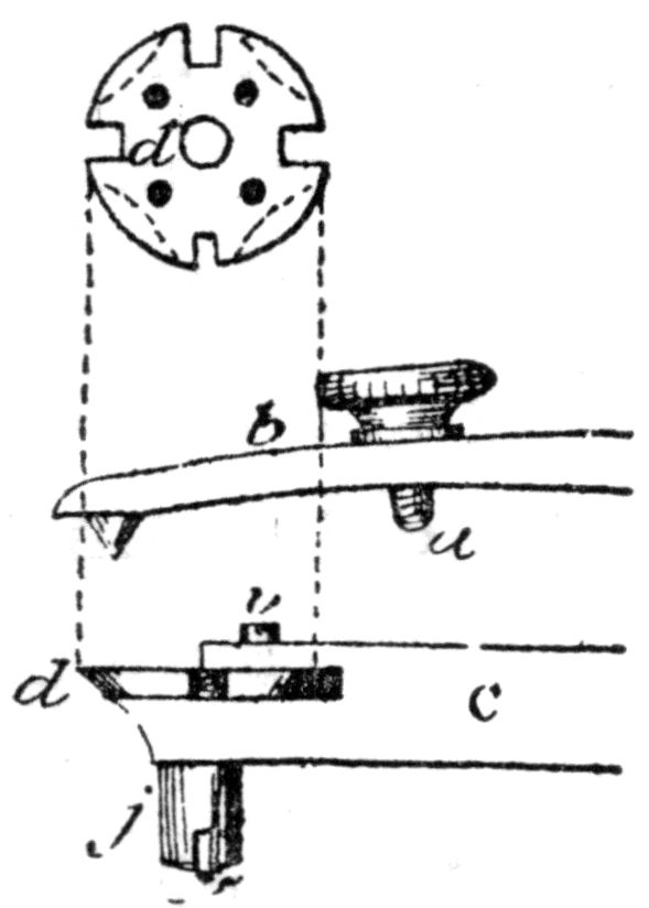
Fig. 156.
333. Tool for Removing Studs. Fig. 156 represents a small tool which may be employed for this purpose. It consists of a thick strip of metal, C, spreading out like the letter T at the end which is not shown, so as to form two feet, the screw, j, being a third, so arranged that the T rests horizontally. The disc, d (shown also in plan), rotates on the screw, j, and is partially enclosed in a horizontal slot. Around the circumference of d are four rectangular notches of different sizes. The holes indicated by black dots on the plan receive the point of the screw, v, which clamps the disc when the notch corresponding in size with the stud to be removed has been brought under the small cone projecting from the spring, b; the other end of b is fixed to the T-shaped piece, C. The mode of using this little instrument will at once be evident. Resting the right arm on the bench, and, with the left-hand, bringing the wing of the cock above the notch in d, the other hand presses upon the milled button of b, forcing the conical pin against the stud and thus removing it from the cock. The screw, a, can be adjusted so as to prevent too great force being applied.
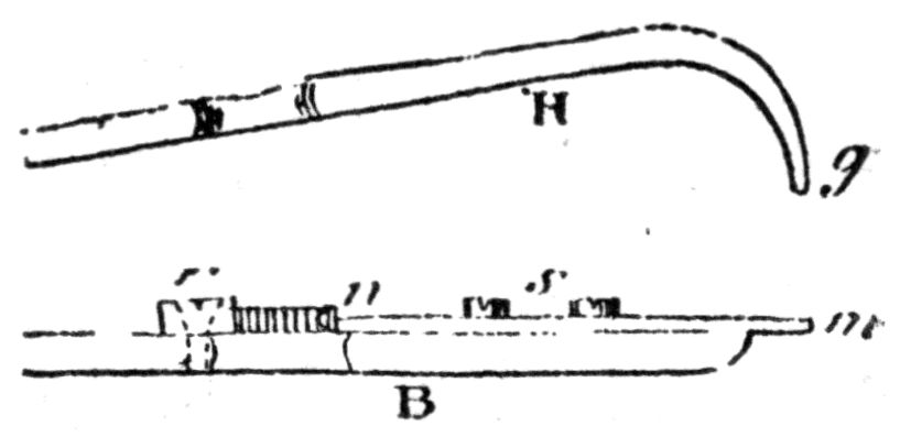
Fig. 157.
334. Tweezers for Removing Studs. One form is shown in Fig. 157. The upper arm, H, is bent downwards as indicated at g. The lower arm is shorter and carries a separate piece, n m, which slides under two screws, s, and is pressed forward by a spring, r. The action will be easily understood; the extremity, m, rests against the stud, and m n is forced backwards until the point, g, is exactly over the stud pin. A simple pressure of the finger will then suffice to remove the stud.
A still more simple pair of tweezers for this purpose may be made by filling a square notch in the end of one prong of an ordinary pair with broad noses, and setting a pin opposite to its center in the end of the other prong.
335. Staking Tool. The modern staking tool will perform the same work as the last two tools described and many other operations. It consists of a shifting table, around which holes of various sizes are arranged in a circle, so that any desired hole may be brought under a suitable punch moving in a vertical holder. Usually twenty-four tempered steel punches and four stumps are provided, which will be found sufficient to cover all the operations in the ordinary run of watch repairs, and the ingenious workman can from time to time add to these by making punches in his spare moments, if he finds from experience that he is in need of punches of a different shape. Fig. 158 illustrates the Johanson combination staking tool, on the front end of which a hairspring stud indicator is arranged.
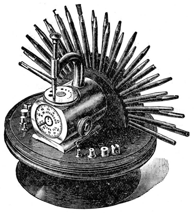
Fig. 158.
336. The staking tool can be used as a cannon pinion tightener by making a punch for it having a blunt chisel edge. When a cannon pinion is placed on a stump which is slightly dished in that portion of its face opposite to the punch, and the punch gently struck with a hammer, it will be sufficiently contracted to insure the requisite adherence to the set-hands arbor. If fears are entertained lest the pinion should be cracked with the blow, it may be placed loosely on an arbor and held in position.
337. It may also be used to advantage for tightening the set-hands arbor in the center or cannon pinion, but care must be exercised or the arbor may be bent so that the minute hand which it carries passes nearer the dial at one place than another.
An arbor that is too loose is introduced into a suitable stump and at the top and bottom of the slack portion two punch marks are made opposite one another. The punch having a conical or three-sided point, will occasion an expansion of the metal round each mark; if a smooth file be passed over the surface so as to remove the burr, which would not offer any permanent resistance, sufficient projecting metal will be left to secure a sound and lasting friction when a little oil is applied.
If the arbor is well supported immediately beneath the punch, it will not be distorted by any moderate impact. It is advisable before operating on the metal to ascertain its degree of hardness.
338. It may also be used as a pinion riveting tool. The pinion, with its wheel in position, is placed on the hardened steel stump, the end to be riveted being upwards. The riveting is then struck with the polished end of a hollow punch. If it be required to spread the riveting, a punch must first be used that is rounded from within outwards, to be followed with a perfectly flat punch. A little practice will at once enable a workman to select the best form of punch.
The stump should be very hard and polished, funnel-shaped downwards and carefully fitted to the bed, so as to be firm and central with the punch. If these precautions are not taken the pinion will spring and the riveting will be imperfect.
339. The staking tool may also be used for closing up barrel holes, screw-holes, etc. In repairing watches it is often found that the screws hold badly or not at all, and the holes at times cannot be satisfactorily bushed. In such cases it becomes necessary to close them, an operation which any intelligent workman can perform very well in the following manner: Make a stump rounded at the top and provided with a pump-center. This can be merely a pointed steel rod that passes through the stump from below with slight friction, and is forced upwards by a light spring fixed by a screw, so that, on undoing the screw, the rod can be removed. The one pump-center can be used for various stumps as the openings are funnel-shaped downwards. Center the hole to be closed by means of the pump-center, then bring down the hollow punch and strike it as in riveting a pinion. A small circular groove will be formed around the hole, which, if the punch is in good order, will be perfectly even. The form of the punch is very important; the watchmaker must decide for himself by trial as to the most convenient shape. The thickness of the ring of metal may be modified; it is rounded off in a semicircle by some, and curved inwards or outwards by others.
Instead of a pump-center below we have used punches that were themselves provided with a pump center and helical spring. Either form gives satisfactory results.
The holes of barrels can be closed with a punch that is only depressed at its center enough to avoid the point of the pump-center. When the face is more or less rounded the hole will be closed by forming a cup as with a chamfering tool. The tool may then be enlarged if requisite with a round broach or an arbor covered with white wax. It will thus be hardened, and the cup-shaped recess will serve to retain the oil, while the somewhat thinner hole will probably be in a condition to resist friction as long as formerly.
When the hole is of moderate thickness, and it does not require much reduction in diameter, this method will be found satisfactory; barrels that have been thus treated have been found to stand ten years without appreciable wear. When the metal is thicker, however, the spreading inwards is very slight, and there is some danger, in using a round broach to do it, of straining the metal or detaching the central ring of the barrel or its cover.
It should be observed that the methods explained above are absolutely useless for closing pivot-holes, and should only be resorted to for barrels, on an emergency.
340. Drifting Tool. This appliance, shown in Fig. 159, is very useful for making holes of round, oval or square, or, indeed, any required form. It takes the place of a punching machine for light work.
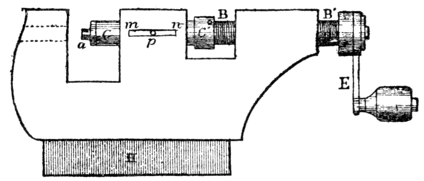
Fig. 159.
The punch, or “drift,” is screwed into the stock C C′. A pin, p, fixed in C C′ prevents its rotation while allowing an end motion along the slot m n. The end C′ is hollowed out to receive the point of a screw, B, and a pin, shown near C′, is received in a groove turned in B, thus enabling it to draw the stock in the direction C C′. The part H is gripped in the jaws of a vise, and a strong handle, E, is used to advance the screw B B′. With a tool about three times the size of the figure there is no difficulty in punching the eyes of mainsprings, square holes in stop fingers, etc., and it can be made by an apprentice. Of course its strength depends on the pitch of the screw and the radius of the handle E.
341. For heavier work it will be necessary to resort to the punching machine. There are several constructions in use, but the most usual is essentially the same as that of the tool just described. The screw works vertically in a strong bridge that is fixed to the bed in which the counterpart of the punch is held. Great use is made of this machine in factories at the present day, almost every part of a watch being in the first instance roughly shaped by its means. Indeed, thin metal is often left as it comes from the punch, and very perfect crossings of wheels, etc., are thus produced.
Steel does not cut well in the press unless it is soft and homogeneous, and the final dimensions of the object can be more nearly approached according as these conditions are satisfied. Attempts have been made to cut levers, etc., of the exact dimensions required, but it is better to leave a slight excess of metal to be afterwards removed by a mill cutter or other means. The crossings of steel lever and cylinder escape-wheels are punched out, but the metal used is of special excellence. Before introducing a piece of steel into the press it is advisable to remove any scale, etc., by pickling, or with a file.
342. Draw-Plate. Every watchmaker should possess a plate for drawing round wire so as to be able to obtain it of any required diameter. They are to be had at all material houses. In bushing holes in a brass plate, it not unfrequently happens that the brass used for the bushing is not of the same color as the plate. To avoid such a difference cut off a piece from a plate of the same color and round it by hand, making one end to taper. Fixing the draw-plate in the vise, pass this end through one of its holes, and, gripping it in the hand-vise, pull the brass through the plate. Continue this operation through successive holes until the requisite thickness is attained.
No special precautions are necessary, further than keeping the holes well greased and annealing the brass from time to time so as to counteract the hardening caused by the operation.
Such a plate can also be used for steel wire, and plates with holes of special form, for example those for drawing click and pinion wire, are well known in the trade.
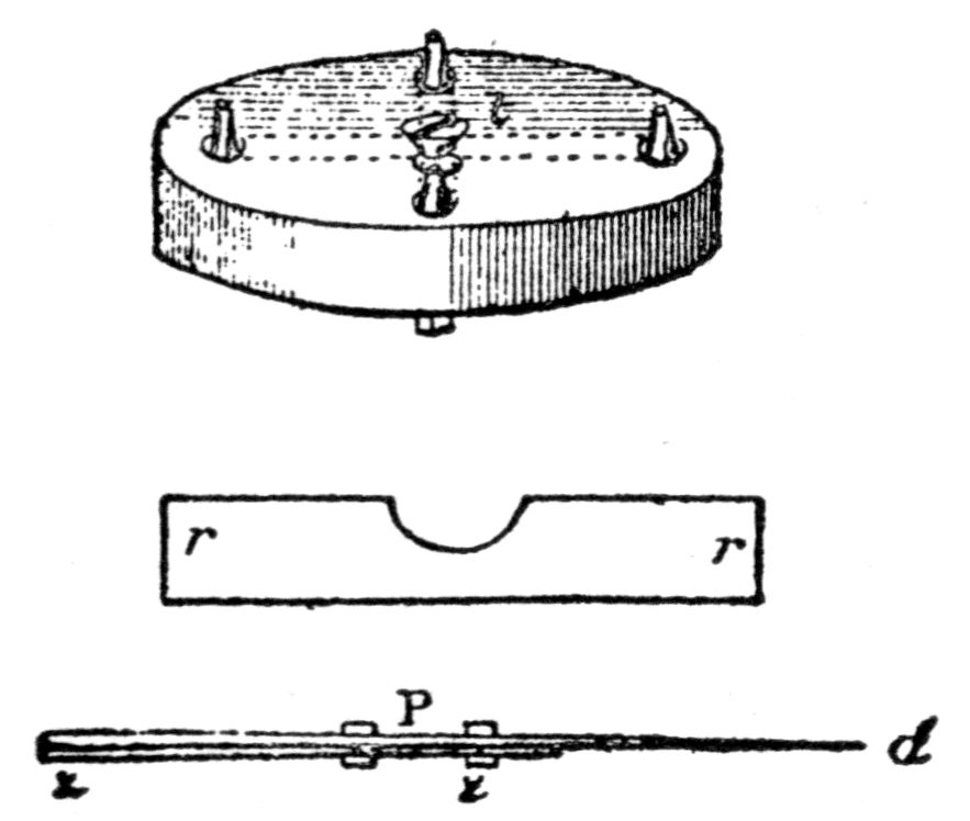
Fig. 160.
343. The Grammaire, or Dividing Plate. This tool is shown in Fig. 160. To mark out the crossings of a wheel, etc., fix it by the conical-headed screw t to the middle of the plate, on which are traced a series of concentric circles (not shown) divided into 6, 8, 10 and 12 equal parts. By laying the little ruler r r over the wheel blank and using these division marks as a guide, 3, 4, 5 or 6 radii can be drawn to serve as guides for cutting out the arms.
If it is desired to indicate the width of the arms instead of a mere central line, a series of holes must be drilled at the division marks and screws with tapered points tapped into them from below. Resting the ruler against these cones, the arms can be drawn of any required width, according to the distance to which the screws project. No further explanation is necessary, for the figure shows: (1) a grammaire adapted to mark out a four-armed wheel, these arms being indicated by the dotted lines; and (2) the small ruler r r cut away at the middle so as to avoid coming into contact with the conical-headed screw.
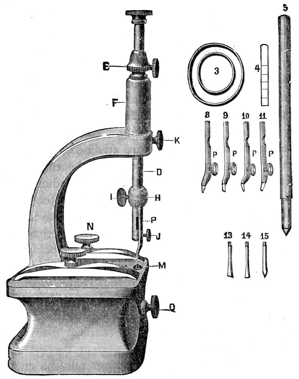
Fig. 161.
344. Jewel-resetting Tools. Hopkins’ patent jeweling and staking tool, shown in Fig. 161, is an ingenious device, and one that will be found very useful to the watch repairer. As the spindle, or handle, to which the cutters and burnishers P P P are attached, is sustained in upright position when in use, by the long bearings through which it passes in the upright F, independently of the lower center, the hole to be cut may be centered either from above or below as preferred; and the depth to which it is desired the cutter shall work is regulated by adjustment of the sliding collar E, and this being a correct uprighting, as well as jeweling tool, with it a pivot hole, or a jewel setting, the correct center (upright) of which has been lost, may readily be corrected, or its true center again found, and, what in some cases would be a very desirable consideration, by careful manipulation with the cutter, which is under perfect control of the operator, the position of jewel settings may be changed so as to alter the depth of locking of the wheels to any desired extent. To regulate the depth to which it is desired a cutter shall work below the surface of a plate, lower the spindle D until, when moved out sufficiently far, the end of the cutter will rest down on the top of the plate to be operated upon, and fasten it there by lightly tightening the screw K; this done adjust and fasten the collar E on the spindle D, to the same height above the top of the upright F as it is desired the cutter shall work below the surface of the plate on which it now rests. This, when the spindle D has been again set free by loosening the screw K, will of course allow the cutter to sink into the hole to be operated upon to the exact distance the collar E had been set above top of F. In adjusting the collar, E, the graduated wedge No. 4, or the jewel to be set, as preferred, may be used as a gauge. The burnishers, No. 9, are used both for opening and closing settings; the same burnisher, having chosen one of proper size, is used for both purposes; the side being used for opening the setting, and the beveled and rounded end for burnishing it down again over the jewel. The pieces 13 and 14 are made to fit in the lower end of the spindle D (the cutter P having been removed), same as an ordinary drill-stock, and are used for burnishing the edges of a jewel setting down flat over the jewel, countersinking screw heads, giving end-shake to wheels, etc.; and being easily made, any one owning the tool can make these for himself, of forms and sizes to suit the particular work in hand. For uprighting purposes, withdraw the spindle D and substitute No. 5, the rings, No. 3, being intended for laying the work on, on the tool bed. For upright drilling through watch plates, mark the place to be drilled (prick punch it slightly) with the cone point of No. 5; which done turn the spindle No. 5 upside down and rest the upper end of the drill in the countersink in its end, the drill being operated with a fiddle bow acting on a collet placed on its shank for the purpose. For cutting off bushings level with a watch plate, either a cutter of the No. 13 or 14 class, or one of the P cutters can be used. For staking or riveting wheels upright on their pinions, lay the stake No. 7 level on the tool bed (the center M having been fastened down out of the way), and with No. 5 center accurately the hole to be used in the stake, and fasten it there by means of the clamps N; then remove the cone end of No. 5, and place a punch with a hole in its end of the required size, on the part m, and proceed as in an ordinary upright staking tool.
345. Tool for Flat Polishing. A thick brass plate is provided with three strong screws arranged in triangular form (G, Fig. 162), and far enough apart to ensure that, if the plate is reversed and rests on their heads, it will remain flat when moved by hand over a polishing surface.
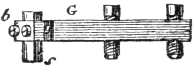
Fig. 162.
The screws should fit tightly or be provided with lock-nuts.
We believe that every watchmaker must be acquainted with this little tool. The object to be smoothed or polished is fixed with shellac or sealing-wax to the middle of the triangle formed by the screws; the level is then adjusted so that, when resting on a flat surface, the object to be polished coincides exactly with it. The polisher (for example, a sheet of ground glass) is charged with oilstone dust or polishing rouge, and the object is passed over it until perfectly flat and smooth.
346. For smoothing, it is best to use a large sheet of iron or steel. For polishing, copper or bronze is preferred. Ground glass may be employed for both operations; it must be hard and perfectly flat.
A disc rotating in the lathe or mandril, etc., is often used.
The tool may be inverted and rest firmly on a cork, the polisher being then moved backwards and forwards by hand, and always in contact with the three screws.
It is best to use pith for cleaning the polished surface; in its absence use soap, then wash and dry with a soft linen rag. The object is detached by heating the tool, and is cleaned by boiling in alcohol; afterwards pass through pure alcohol at the ordinary temperature and dry.
347. This tool can be employed for polishing small surfaces, such as the end of a rod, of a barrel-arbor or a screw-head, as well as for those of greater extent. But it appears needless to enter into further detail.
Instead of three screws some workmen only use two, at some distance apart. The object to be polished, being placed at the third corner of the triangle, takes the place of the remaining screw.
Lastly, if a band be fitted to one side of the brass plate, as shown at b, Fig. 162, and held by two screws, it will often be of service as a clamp for fixing the object, as at s.
348. Flat pieces can be polished on a revolving lap worked by the foot, being simply held in the hand or in a piece of soft leather; but a certain amount of practice is needed in order to do this successfully.
ACCESSORIES AND MISCELLANEOUS OPERATIONS TO BE PERFORMED IN THE UNIVERSAL HEAD.
349. With a view to simplify the work, we will here give, in a collected form, a number of operations that may be performed in the mandril, or universal head, among which the practical watchmaker will easily be able to distinguish those that can be done in the ordinary lathe; we will also describe numerous accessories that the workman should make for himself, if he is desirous of making his mandril or universal head still more generally useful.
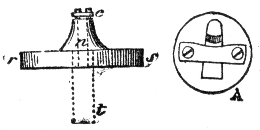
Fig. 163.
350. Prepare a number of chucks of the form shown in Fig. 163. Some of these carry a small bar with screws, by which an object may be clamped firmly to the chuck, an arrangement which is also shown at A, Fig. 163; others have a hole drilled through their axis; others again have a projecting arbor, etc. They may also be made with a flat face on which to cement objects in the ordinary manner.
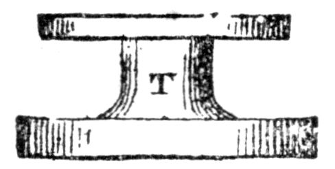
Fig. 164.
As it is often necessary to have a considerable surface to cement, for example, a watch-plate, one or more may be made of the form shown at T, Fig. 164. The lower plate being clamped in the dogs, the disc e will be free. If this disc be made of bronze or steel it may be used as a lap; if of brass, it may be turned true and used as a wax chuck, etc.
The chucks should, as far as possible, be well made, so that they can be truly centered by means of the pump-center.
TO CENTER AN OBJECT.
351. When there is a hole at the center on the side towards the face-plate, in the universal head, as is usually the case, it is only necessary to place this hole over the point of the pump, pressing it inwards, and then to clamp the object in the dogs; the pump is then drawn within the body of the arbor. Very often, however, there is no central hole, or there is only a mark on the face that is towards the cutter; in such a case it becomes necessary to center from the front or by the circumference.
352. To Center from the Front. If the object is held by wax on a plate, it may be centered as in the ordinary lathe while the plate is hot, by resting a piece of pegwood on the T-rest with a point placed in the central hole, and observing whether its free end remains stationary.
After the plate has cooled, the accuracy of the centering should be tested by means of a long piece of pegwood which rests on the T-rest brought close up to the object. The pegwood is held parallel to the lathe-bed, and, if the centering is satisfactory, its outer end will not move. The detection of any slight movement is greatly facilitated by placing some fixed object close to the free end of the pegwood. If a motion is still observed the centering is imperfect, and must be corrected in the manner explained below (354).
353. Perrelet’s method of Centering. In principle, this is identical with the one just described; but the pegwood index is replaced by the small apparatus shown in Fig. 165.
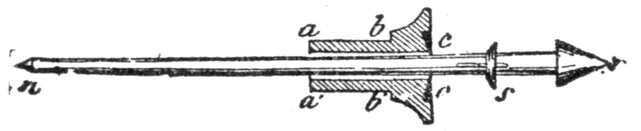
Fig. 165.
A hollow cylinder, of which a c c a′ is a section, is firmly held by friction by its portion a b b′ a′ in the tailstock. In the front of this cylinder is fixed a steel ring that is thick at the circumference and tapers inward, so that the central hole has a cutting edge. The two black triangles represent a section of this ring. The rod r n passes without play through this hole, and carries a projecting ring at s to determine the distance to which it enters the collar c c; there is also a small key that corresponds with a nick in c c, and thus prevents rotation.
An inspection of the figure will show that, when s rests against c c, if the finger be placed on r and communicate motion to it, the rod n r will be able to oscillate in any direction, and to an extent limited by the diameter of the hole in the cylinder.
The error in the centering at r will be multiplied at n in the proportion of n s to s r; thus if n s is ten times s r, the motion at n will be ten times as great as the actual error at r.
354. The instrument is used as follows: The object to be centered being placed between the jaws, having the centering spindle in position in tailstock. Slide tailstock towards the face-plate until the point r of the rod enters the hole, or central mark of the object, and, setting the T-rest close to the point n, rotate the face-plate. If the centering is exact, the point n will remain stationary. If n moves to and fro, give a gentle blow against the edge of the object, which should not be held firmly in the dogs; the blow must be on the side opposite to that at which n shows the greatest deviation from the point of reference. Repeat the process until the centering is perfect or sufficiently accurate; then clamp the dogs firmly, taking care not to disturb anything.
In centering from a jewel hole, an aluminium rod n s may be employed on account of its lightness, and it may be terminated in an ivory cone at r.
355. There is one precaution to be observed, as it facilitates the use of this appliance; it is advisable that the portion a b b′ a′ of the cylinder be somewhat long and well made, in order that, while being in the first instance inserted in tailstock up to the shoulder, the cylinder may be partially withdrawn and still held firmly. The reason for this is as follows: When the tailstock is pushed along, a considerable amount of friction resists its motion, and, as the hand cannot always control this motion, it may happen that r comes up against the object with some force. To avoid this, bring the point near the hole and then rotate the collar in the tailstock so as to gently withdraw it to the requisite amount. The cylinder may, if desired, be fixed by a small screw after the point r has been set in position.
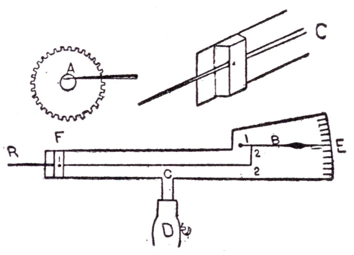
Fig. 166.
356. Another Centering Device. The centering indicator shown in Fig. 166 will also be found useful for testing for exact center. The body of the indicator is made of sheet brass, and should be about five inches long by two inches in width at the larger end. The shank C is made to fit in rest holder, and is either riveted or soldered to the body; R is steel or copper wire sharpened to a fine point, and balances on a pivot at 1; B is a clock hand pivoted to the body at 1; 2 and 2 are pivot joints only, and do not go through the body; C will perhaps give a better idea of the end R. To center with this tool, unscrew your rest and remove it, then place the shaft C in rest holder and adjust it till the needle point R touches the top of hole, as shown at A. The index hand will then note the variations as the head revolves. If too low, the hand will point above center, and if high, vice versa.
357. To Center from the Circumference. Two cases may occur: Either the entire rim of the object is exposed, as when the teeth are to be cut in a wheel blank; or the rim can only be used as a means of determining the center, as when a barrel has been bushed with an undrilled bushing.
358. The tool shown in Fig. 166 may also be used for the test if the short end of arm R rests against the under side of the object that it is desired to center.
359. When it is required to drill or merely to center the hole in a wheel, barrel, etc., that does not run true, clamp a piece of sheet brass in the dogs and turn out a sink that will exactly receive the wheel, etc., but allowing it to project slightly. Now unscrew one dog and advance it a little, so as to grip the edge of the object as well as the plate; move the other dogs inwards in succession, and it will only remain to drill or true the hole with a suitable drill.
UPRIGHTING AND DRILLING.
360. When the Lathe is Provided with a Tailstock. Let it be required to mark and drill a pivot-hole in the cock when the plate-hole is accurately centered by means of the pump-center. Place the tailstock in position on the lathe-bed, and mark the position of the hole with a center, as in an ordinary uprighting tool; then, if the hole is to be very fine, make it with an ordinary pivot-drill.
If the hole to be drilled is somewhat large, it may be drilled with the twist drill, the bed of the lathe being, as usual, horizontal.
361. When the Lathe is not Provided with a Tailstock. In such a case it is possible to upright and drill by using fine drills, and making points so formed as to take the place of the cutter. Or a stock may be made to receive drills, points, etc., and it may be well here to remark that stocks of the same form are convenient for receiving chamfering or sinking tools.
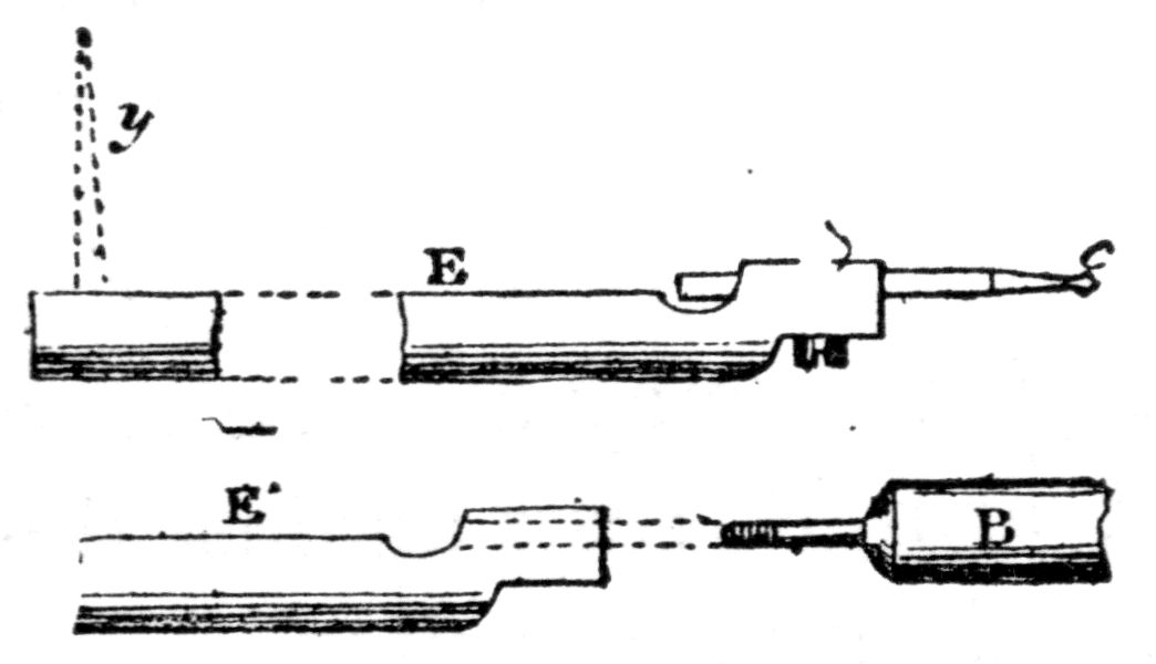
Fig. 167.
This stock is shown in Fig. 167. An inspection of E c will suffice to show its form, and it may be used for holding either a drill or a marking point, or a small hollow center in which to support a pivot drill.
The following method should be adopted for securing accuracy in the adjustment of these stocks:
There must be no shake of the stock in the tool-holder; it is especially important to avoid any displacement during the act of clamping. If there is any reason for doubt on this point, drill a hole at the foot of the cutter in which an index, y, can be temporarily inserted; any displacement can be detected by its deviation from a fixed mark. As a rule, however, there will be no occasion for doubt if the plate that is screwed down upon the stock is parallel to the bed of the tool-holder.
The cutter is then replaced by a stock of the form shown at E′, in which a hole has been previously drilled to receive the drill or other bit, but somewhat smaller than it is required finally to be. The pump-center must now be replaced by an accurately fitting piece B that terminates in a short semi-cylindrical drill.
It will be evident that if the mandrel be revolved, and, at the same time, the tool-holder advanced towards this drill, the hole in the stock E′ will be enlarged and smoothed, and its axis will accurately coincide with that of B. Any drill, chamfering tool, etc., that has been turned true, will, therefore, on being inserted in the stock, prove to be strictly in the axis of the lathe.
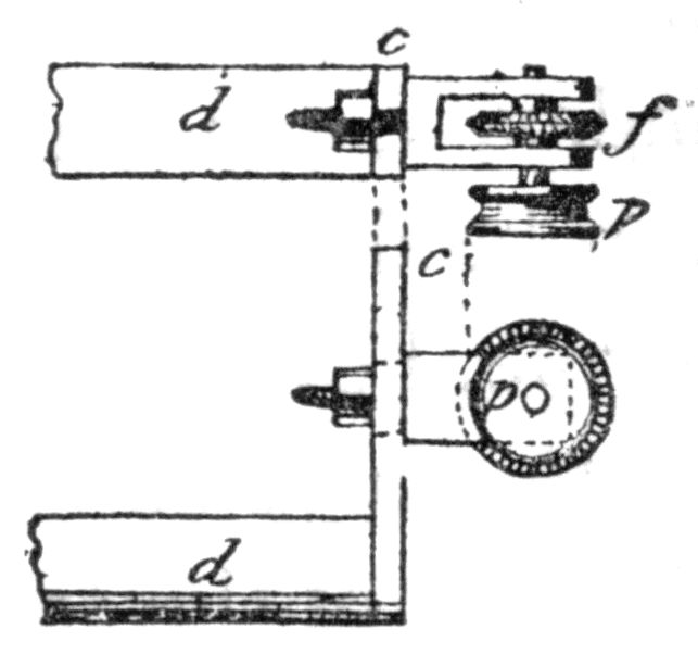
Fig. 168.
362. To Drill a Series of Holes. Mount on a stock similar to that just described, a small frame carrying a drill-stock, as shown in Fig. 168. If this be fixed in the slide-rest in place of the cutter, it can be used for drilling a hole or a series of holes previously marked out, or, if the pitch of the transverse screw of the slide-rest is known, for a series of equidistant holes in a horizontal line. When it is required to drill a series of holes in a circle, as, for example, in the escape-wheel of the pin-escapement, bring the point of the drill onto the circumference and then proceed as when using the ordinary wheel-cutting engine provided with a vertical drill-holder, taking care to fix the face-plate by means of an index.
This index should have a means of slightly modifying its length, so that the point of the drill may always be brought into exact coincidence with the points that have been previously marked on the object.
It will be observed that, if the drill were replaced by a round milling tool, the U’s of a cylinder escape-wheel might be polished, or, indeed, cut, the concave ends of the teeth of the star-wheel in a Geneva stopwork could be corrected, etc. But it is unnecessary further to insist upon the many uses to which this form of tool can be applied.
363. To Cut the Teeth of a Ratchet, Minute-Wheel, Etc. When the face-plate is divided on the circumference, it is easy to cut the teeth of an ordinary wheel of a timepiece, escape-wheel, barrel ratchet, to cut or true a star-wheel for the stopwork, etc. After mounting the wheel on a chuck and carefully centering it, replace the cutter by a small revolving cutter-frame after the model of that shown in Fig. 168.
The stock d, shown in both plan and elevation, carries a piece c at right angles, which has a slot cut throughout its length. In this slot a U-shaped support can be clamped by a nut in any position. The U portion forms a bearing for a cutter, such as is shown at f in the figure, and the axis projects so as to receive a ferrule for rotating the cutter.
It will be evident that, with such an arrangement, the height of the cutter can be adjusted in accordance with the teeth to be cut.
364. To Cut a Circular or Elliptic Groove. For this purpose no special accessory is needed; an ordinary cutter will suffice.
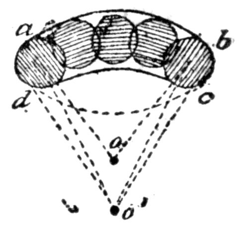
Fig. 169.
Let a b c d, Fig. 169, be the form of the required groove. Mark a series of centers so that circles struck from them will just overlap one another, and at the same time nearly reach the edge of the groove. Then turn out all the circular sinks, indicated by shaded lines, to the required depth.