PART IV. TOOLS AND APPLIANCES.
Reading edition
WORKSHOP FITTINGS.
229. Before proceeding to describe the various forms of lathes and the several small tools that the watchmaker should make for himself as occasion offers, either during his apprenticeship or immediately after, with a view to increase his manual skill or to extend his experience, it will be well that he take note of the principal conditions that should be satisfied by the ordinary tools that he will have to buy, as well as the precautions to be observed in their use and some improvements of which they are capable.
230. The bench or board. This should be fixed in front of a large window that affords a good light. The various hooks, recesses, etc., for holding files, hammers, etc., as well as the drawers, should be well in sight, not only in order that the hand can at once take hold of whatever tool is required, but also to enable the workman to restore them to their place immediately after use. By doing so he will have no occasion to retain on the bench any but those tools that are very frequently or continuously used.
It is an excellent habit, conducive both to well-planned and rapid work, and which can be easily acquired by a little attention during an apprenticeship, to always place the same tools in the same places, as the bench will then never be encumbered. By this means loss of time in turning over a number of objects in order to find one that may be small is frequently avoided.
This observation is of minor importance to specialists who require but a small number of tools; but it is of the first importance to a workman that is engaged in the repair of watches.
231. The stool. Those with cane seats are to be preferred. The height of the bench and stool should be so related that the muscles of the chest are not too much cramped, especially if the workman is engaged on an operation that occupies a long time and obliges him to maintain a stooping position. The stool with a screw is advantageous in this respect.
232. The lamp. Certain precautions in regard to artificial light have already been indicated in article 218.
233. Oilstones. It is impossible to maintain the points of gravers in good condition if care is not taken to keep clean and flat the surface of the stone on which they are set; if it has suffered irregular wear, the level may be restored by rubbing the stone on a flat, smooth board, covered with a thin paste of fine sand and water. Most kinds of oil thicken on the surface rapidly, when the graver will slide over without being ground down at all, turning around in the hand and thus destroying the flat face and wearing the softer parts of the stone, rendering it uneven. A strong solution of potash or soda is very effective for removing this gummy mass; benzine is also recommended for the same purpose. Various substitutes for common oil are used; such as the mineral lubricating oils or petroleum. Dr. Latteux advocates the use of a mixture of alcohol and glycerine, the proportion of the latter decreasing as the extent of metallic surface in contact with the stone at once increases. Thus, for example, in setting a razor the stone will bite better if alcohol be in excess; but for a graver, of which only a small surface touches the stone, the amount of glycerine present should be relatively much greater.
234. Circular oilstones. Circular oilstones will be found very convenient for sharpening drills, gravers and other cutting tools, where it is desirable to have exact angles. An Arkansas or Turkey stone dressed down to circular form, and say 1½ inches in diameter, when mounted for the lathe will be found very useful. Apply the lubricant to the stone the same as you would to a flat one, and hold your graver or drill at the exact angle you wish the cutting edges to be and turn at a moderate speed. Truer angles and better work can be produced in this manner than by any other. Emery or corundum wheels can be mounted in a similar manner. Small circular stones can be obtained from material dealers and dental supply houses, in sizes varying from ½ × ⅛ to 3½ × ¾ inches. They can be mounted similar to Fig. 49, by turning down a piece of No. 30 Stubb’s steel wire to the size of the opening in your wheel and riveting the wheel firmly upon it. The best sizes for watchmakers’ use are ½ inch, 1 inch and 1½ inch in diameter.
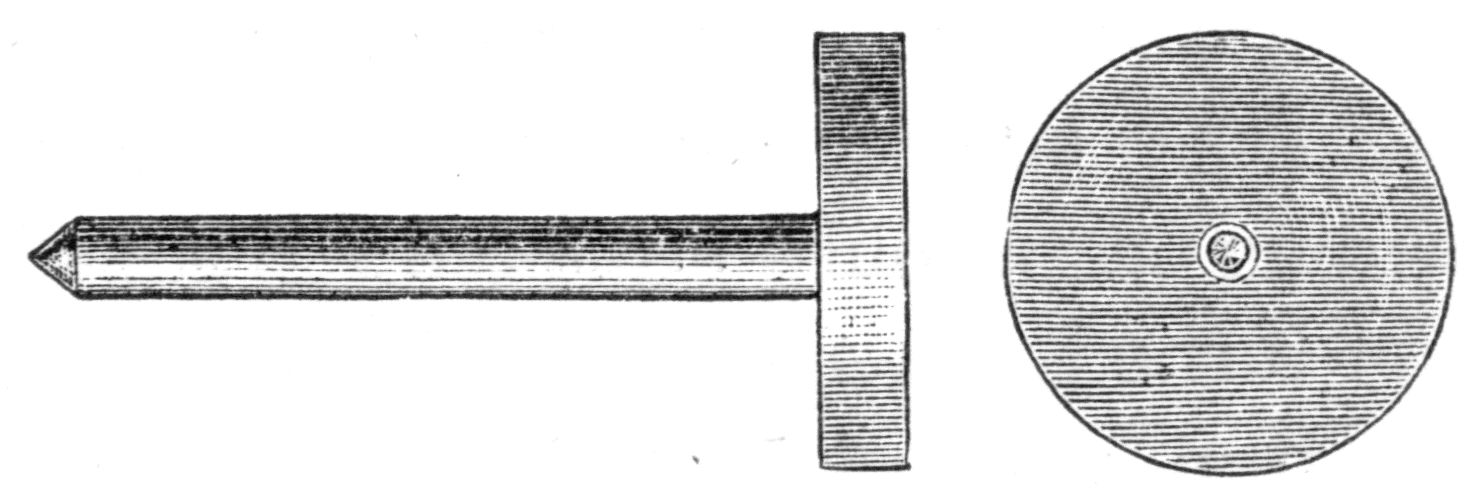
Fig. 49.
235. Small grindstones. When it is necessary to remove a good deal from the face of a graver, the operation will take too long on the oilstone, and there would be considerable difficulty in maintaining the flat face; recourse must then be had to the grindstone, but it should be remembered that care is needful when using it. The grindstone must always be thoroughly wet in order to avoid heating the graver, as its cutting power would then be destroyed. The emery wheels described in paragraph 165 can be used for this purpose, but they are, for the most part, inconvenient on account of the rapid increase they occasion in the temperature of the metal. Some forms of emery wheel can, however, be moistened just as the grindstone.
When the cylindrical surface is rendered irregular by use, take a piece of sheet-iron, the tail of an old file or a cold chisel, and hold it with one hand firmly on a support against the edge of the stone, which is rotated by the other hand. The surface can thus be made smooth and true, providing it is only attacked gradually and the handle is not turned too rapidly. An excessive velocity will heat the iron, which is then less effective and is more rapidly worn down; whereas, with a slow motion, the iron will relatively wear little and the stone more. A rough diamond mounted at the extremity of a steel rod, affords an excellent means of trimming a grindstone, and is at the present day generally used in factories.
236. Glasses. Some particulars have already been given in regard to these simple microscopes in article 218.
237. Files. A new file should never be used for steel; it is best to employ it for some time at first on brass, taking care not to use it too roughly. If employed to steel at once, or if sharp, quick strokes are applied, the cutting edges of the file will chip off, and the hard particles will be embedded in the metal operated upon; the work will thus be bad, and the file itself deteriorated. A file that has been carefully used, and has passed gradually from brass to steel, will last four or five times as long, and will always work well.
Watchmakers often fit files into handles by driving them firmly into round holes in the handles; this practice frequently leads to the handles being cracked, and the following method is preferable: Take an old worn out file or a piece of iron of the same form as the tail of the file to be fitted; heat it several times to bright redness and drive it, when so heated, into the handle, taking care to maintain it perpendicular. A hole will thus be made of the required form, in which the file will hold without there being any occasion to apply excessive force in fixing it in position.
When the surface of a file is choked with particles of iron, copper, wood, etc., while the cutting edges are yet good, it can be cleaned as follows: Place the file for a few seconds in a hot lye of potash in water, and on withdrawal, dry it before the fire and brush the surface with a stiff brush.
238. To renew the cutting edges of files, either of the following methods can be adopted: 1. First clean the file with potash or soda dissolved in water, if greasy or resinous substances have to be removed; with hydrochloric acid if it is rusty; and by rubbing with a metallic brush or piece of coke if particles of iron, brass, lead, copper or tin have to be removed. The file is now immersed in a mixture of 1 part nitric acid, 3 parts sulphuric acid, and 7 parts water. As the action of the acids become less energetic owing to the combination with iron, the temperature of the mixture must be raised, since rapidity is a condition of success. The time during which the file should remain in this bath varies from 10 seconds to 100 or more, the roughening of fine-cut files being far more rapid than when they are of a coarser cut. On removal from the bath, immerse in lime wash, dry, and then cover them with a mixture of oil and turpentine by means of a brush, after which they are ready for use. 2. After being cleaned, as explained above, the file is supported in a dish full of water, resting on two cross wires, so that all its surface is in contact with the liquid. Now add strong nitric acid in the proportion of 1 part to 8 of the water, mix it thoroughly and allow it to remain for 25 minutes. Remove the file, and, after washing in water and rubbing with a hard brush, place it again in the bath, to which a second eighth part of acid is now added, and leave it for 50 minutes. Again remove and brush the file, add a sixteenth part of concentrated sulphuric acid, and replace the file in the bath. Then wash successively in pure water and in lime wash (to remove the last traces of acid), and dry. The file will be found to possess both the qualities and the appearance of a new one.
239. To cut an equaling file. It often happens that a workman is called upon to modify the shape of, for example, the bottom of a rectangular notch, and he is not provided with a file of suitable shape. In such a case he can adopt one of the following methods of extemporizing a file:
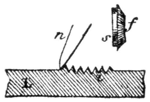
Fig. 50.
1. Clamping the small steel strip, L, Fig. 50, in a vice, cut the notches with a chisel, n, as follows: Holding n a little inclined, cut the first notch, i. This will slightly raise the metal, presenting a rounded face at the back. To make the next cut, hold the chisel with its edge on L and, after drawing it backward until arrested by the back of i, incline it to the requisite amount and give a second blow with the hammer, then continue the operation till the whole is finished. A few trials will enable any workman to make a small file with sufficient accuracy for his purpose.
2. Employ an arrangement similar to that of the micrometer divider (44) only more rigid. A study of this article and examination of the corresponding figure will afford all the information that is necessary.
3. This is identical with the method of dividing a rule described in 46, except that the divisions are closer together and the tracer is replaced by a revolving cutter with its axis a little inclined, to give the requisite slope to the teeth of the file. This cutter is supported in a hinged frame and provided with a washer of ivory or other such substance, as seen at s, Fig. 50, to determine the depth of cut.
240. Beaupuy files and burnishers. Most watchmakers are acquainted with the files and burnishers that M. Beaupuy has introduced for rapidly forming conical pivots, the main characteristic of which is that the corner presented to the pivot is rounded to the desired form and roughed; they do their work rapidly and well, but some skill is necessary in their management. To the instructions which accompany them we would add the following:
They must never be used when quite new on a pivot that is to be employed in a watch; it will be reduced too rapidly. The freshness must be worn off the cutting edges of the teeth by preliminary use.
The pressure must only be applied perpendicularly to the surface of the staff as in making a square-shouldered pivot; the file is held against the flat surface without pressure. A lateral force will have the effect of straining the pivot and causing it to break.
241. Pliers, tweezers, etc. It is advisable to have a considerable number of these, as their strength should always be proportional to the force that has to be applied to them. For example, if a pair of sliding tongs is used when a hand-vise is needed, the former will be strained beyond its limit of elasticity and the tool becomes nearly useless.
The same might occur with any other form of pliers or tweezers. In the hands of a good workman they will last for a long time, but if used unintelligently, without proportioning the size of tool to the force that has to be applied, taking up the first that comes to hand, all the tools will soon become unsatisfactory and the work itself will suffer. It is very desirable to have one or more pairs of brass pliers and tweezers for handling metal work without the risk of scratching.
242. Compasses, gauges, micrometers, etc. The common compass for measuring thickness, the douzieme gauge, is not always strictly accurate in its indications. The douzieme proper, has a scale divided into twelfths, though some patterns are now made that have a scale divided into tenths and hundreds of an inch and again there are others that measure the fractions of a millimeter. The greater majority of these tools on the American market are correctly divided, but we sometimes come across those of foreign make that are divided incorrectly and care should be used in selecting. In the inaccurate tools the objection is that the opening of the jaws gives a measure of a chord whereas the displacement of the index measures the arc of a circle. It follows from this, that, if the index is first arrested when pointing to 15, for example, and again when at 30, the interval between the jaws in the second case will not be exactly double the first. Before purchasing, it is well to test the gauge for accuracy in this regard by some reliable standard.
243. Caliper for mainspring height, depth of sink, etc. A simple instrument for taking such measurements is shown at G, Fig. 51.
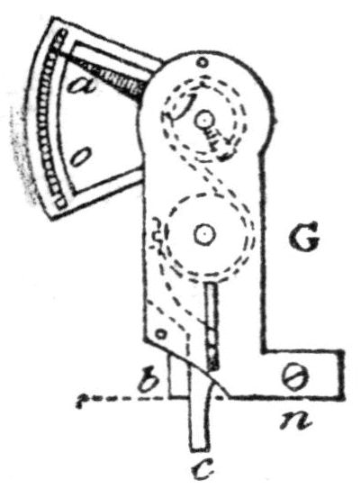
Fig. 51.
The finger a travels over a graduated arc whenever the rod c is pressed inwards; b is a fixed stop, with its extremity in the plane of n. Any movement of a below o measures the space traversed by c within the line b n.
Laying a coiled mainspring, for example, on a plane surface, stand the base n of the caliper upon it, and the end c pressing on the table will be forced upwards and move the needle. To take the depth of a barrel, press c on the bottom, allowing b to rest on the edge of the cover recess.
It will be evident, from the figure, that a and c are connected by a spring passing around drums at corresponding axes. The smaller j is, the more sensitive will the instrument become.
244. Figure 8 caliper. For ordinary work, the calipers to be bought at material stores will suffice; but when it is required to verify escape wheels, balances, etc., there is some risk of accidents in consequence of the variableness of the friction at the joint. To remove this source of danger, true the rubbing surfaces in the mandril and replace the brass discs at the center by similar discs of steel, then carefully re-make the rivet that forms a hinge, after oiling all the acting surfaces. The arms will now move with a uniform degree of stiffness, so that there need be no danger of jerks.
245. Riveting stake and punch. The holes in a riveting stake are made to increase downwards, so as to avoid any accident occurring through the oscillation of the axis. The riveting punches made of a plain steel rod, with a hole drilled at one end in the direction of the axis, are the best. Those that are perforated transversely like the lanterns of screw-point tools, do not produce such good riveting, since the parts of the end, from behind which metal has been removed, are more or less elastic.
246. Burnishers. Burnishers will not remain in good condition unless their surfaces are prepared, from time to time; in the case of those used for very fine work, by passing over a buffstick charged with polishing rouge or very fine emery, and other kinds on an emery stick more or less fine, according to the degree of roughness the burnisher is required to possess.
247. To re-face a burnisher. Pivot burnishers are usually re-faced by a lapidary; a watchmaker can, however, do it for himself very effectually in the following manner: Prepare a dry, smooth piece of wood, rather thick, and of a width equal to the length of the burnisher. On this board carefully glue a piece of emery paper, of a fineness corresponding to the degree of cut required, stretching it as even as possible, and turning the edges down towards the under side. Then lay the board on a firm smooth surface, resting a weight upon it, and allow it to dry.
In using this lap, it is fixed or allowed to rest against the side of the bench; holding the burnisher with two hands at its extremities, the workman places himself at one end of the board, and draws the burnisher along it towards him, maintaining the surface quite flat and applying considerable pressure. On reaching the nearer end, raise it, and after again placing it on the farther end, draw towards the body, and so on.
By proceeding in this manner and always in the same direction, placing the burnisher so that the acting edge is farthest away from the operator, all risk of rounding this angle will be avoided.
248. Broaches. Great care is needed in adapting handles to broaches. Resting the point against a finger of one hand and causing the handle to rotate by two fingers of the other hand, the broach itself should be seen to remain true.
It is a good precaution, suggested by M. H. Robert, to gently draw a piece of iron, charged with rouge, along the edges of pivot broaches in order to remove the thread of metal from them. Minute particles of this thread would otherwise remain in the holes, and occasion wear of the pivots.
These fine broaches are not fixed in handles, but a piece of sealing-wax is melted on to the upper end; then, holding the broach between the fingers, with its stem downwards, it is rotated while held to a flame, so that the sealing-wax forms a regular, oblong handle.
249. Blow-pipes. In order that a long even flame may be obtained, the hole should be of moderate size and perfectly clean around the edge; otherwise the jet cannot be straight and sharp. Difficulty will always be experienced by anyone who has not learned to breathe without interrupting the continuity of the blast. Where a supply of gas is available, the gas blow-pipe presents advantages from the point of view of convenience.
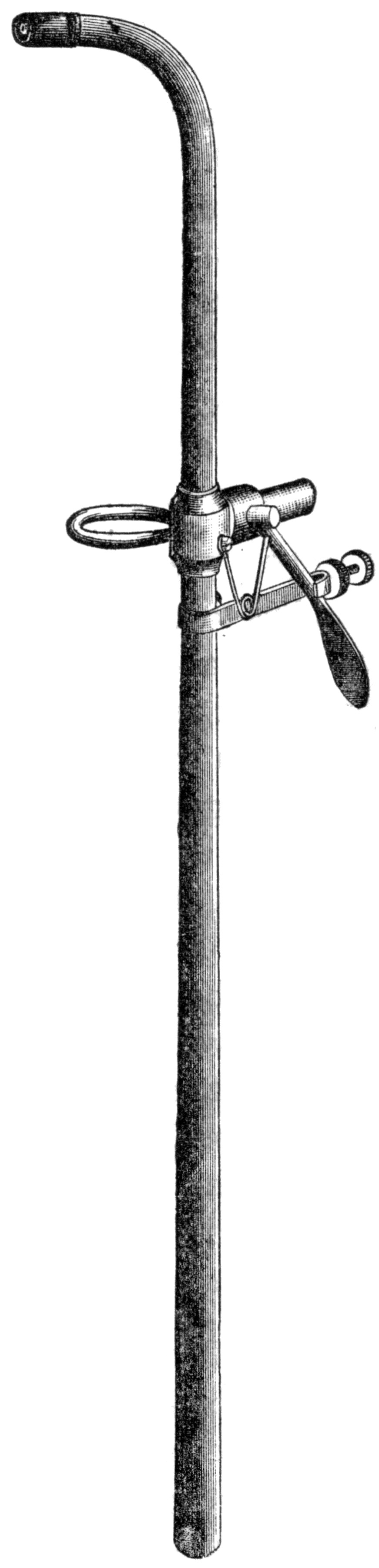
Fig. 52.
Fig. 52 shows a gas blow-pipe for jewelers, which is simple and convenient. It consists of a blow-pipe of the ordinary form, having a gas pipe inserted in the lower half, and a threaded hood or sleeve at the lower end, which changes the shape of the flame by screwing in or out, so as to vary the influence of the current of air upon the flame. A ring adapted to slip over the finger while working, is soldered to the middle joint of the pipe, and the quantity of gas is controlled by the stop-cock and spring lever shown in the cut, the gas being supplied to the pipe by a rubber tube connecting it to the nearest gas jet in the usual way. Thus having the shape of the flame under control and the quantity variable at will, the workman is in position to accomplish the desired end speedily and effectually.
To use to the best advantage, set the jamb-nut so that with the valve lever in its normal position, the flame at the end of the pipe will just keep alight. The blow-pipe can then be laid down temporarily and again used without the trouble of turning off the gas or relighting.
When used as a mouth blow-pipe, the most convenient way to hold it is with the third finger through the ring. For bellows work it is better to pass the ring over the index finger. The ring also serves, with the valve-lever, as a rest to hold the flame-nozzle away from the table when the blow-pipe is laid down temporarily.
To produce an oxy-hydrogen flame, connect the air-pipe with a cylinder of nitrous oxide, opening the cylinder-valve carefully, so as to permit the escape of only sufficient nitrous oxide to produce with the illuminating gas a very small flame. Regulate the illuminating gas flow with the thumb-screw or with the finger on the lever of the blow-pipe valve.
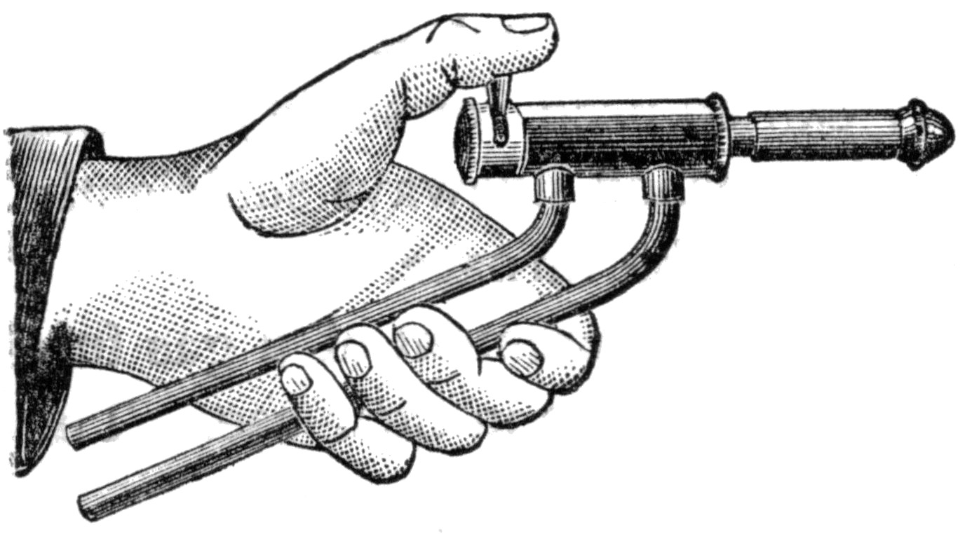
Fig. 53.
Fig. 53 shows an automatic hand blow-pipe for use with a foot blower. One of the rubber tubes shown is connected with the blower and the other to the gas supply. It is self adjusting for both gas and air, requiring only a slight motion of the lever, shown under the thumb, to obtain instantly any flame, from the smallest to the largest; so that these pipes have all the delicacy of the best mouth blow-pipe, used with the utmost skill, together with the power and advantages obtained with a mechanical blower.
250. Small gas furnaces. The workman will frequently have occasion to anneal pieces of steel or to raise to a red heat objects that are too large for the blow-pipe; an ordinary open fire aided by bellows is often resorted to in such a case. A better plan, however, is to use any small portable gas furnace, provided with a hood that completely closes it at the top.
Fig. 54 shows a gas melting furnace, which is kept by material and supply houses. It is powerful enough to melt gold, silver, brass and copper, but is not recommended for cast iron. It can be used for scorifying and cupelling. The lid can be pushed sideways sufficiently to give access to the interior of the furnace.
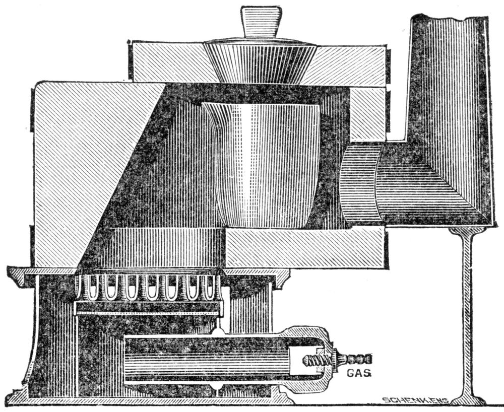
Fig. 54.
The following points in the management of a gas furnace will be of service to all novices in their use. The power and speed are practically without limit, depending only on the gas and air supply, and are under perfect control. Allowing five cubic feet of gas for heating up, it requires about four feet of gas for every pound of cast iron melted. For small work it is as cheap as a coke furnace, and not one-quarter the trouble.
The quantity of air required depends upon the gas supply. One must be equal to the other, so that perfect combustion will take place, and that entirely within the furnace. An excess of either gas or air renders a high temperature an impossibility.
See that all gas taps have a large clear way through. High temperatures and rapid working require a free supply of gas.
To adjust a new furnace to its highest power, connect both gas and air supply with the burner. Turn on the full gas supply, light the gas, the air-way being full open, work the foot blower and then put the gauze nozzle of the burner tight against the hole in the casing, so that no flame escapes around it. If the flame comes out of the lid about two inches, the adjustment is right. If the flame is longer, open the air check until the proper flame is obtained, or reduce the gas supply. If smaller, or not visible, close the air check until the flame appears.
The cap-nut, which will be found at the throat of the horizontal “mixing tube,” where the air enters and mixes with the gas, is used for changing the size of the orifice from which the gas escapes. When the escape is from a large orifice, a smoky, yellow, or “reducing” flame is the result. By contracting the orifice by screwing the cap-nut on to the gas delivery tube, a blue or oxidizing flame will be obtained. Adjustment for the proper flame should first be made by this nut, and the size of the flame regulated afterwards by means of a cock at the gas main. A slightly yellow flame gives the best results when a high heat is desired. The arrangement above described is clearly shown at the left-hand lower corner of the sectional illustration above.
A chimney or stove-pipe 8 or 10 feet high may be used as a fixture, and the draft partially stopped by the damper or slide when lower temperatures are required, the gas being turned down in proportion; the guide for the proper adjustment being that UNDER ALL CIRCUMSTANCES THE FLAME MUST JUST COVER THE CRUCIBLE OR MUFFLE, but not extend into the chimney so as to make it red hot. When the flame covers the crucible or muffle, the gas is doing its extreme duty under the most favorable circumstances, without waste.
Keep all fluxes away from the furnace jacket, as they are injurious to fire clay, and are liable to cause the lids, etc., to stick to the furnace.
A thin layer of quick lime on the bottom of the furnace will prevent the crucible adhering to it when very hot.
When using a furnace for high temperatures, care should be taken not to use a fire clay casing, as it melts at a temperature a little above that of cast iron; plumbago or asbestos only should be used when very high temperatures are required.
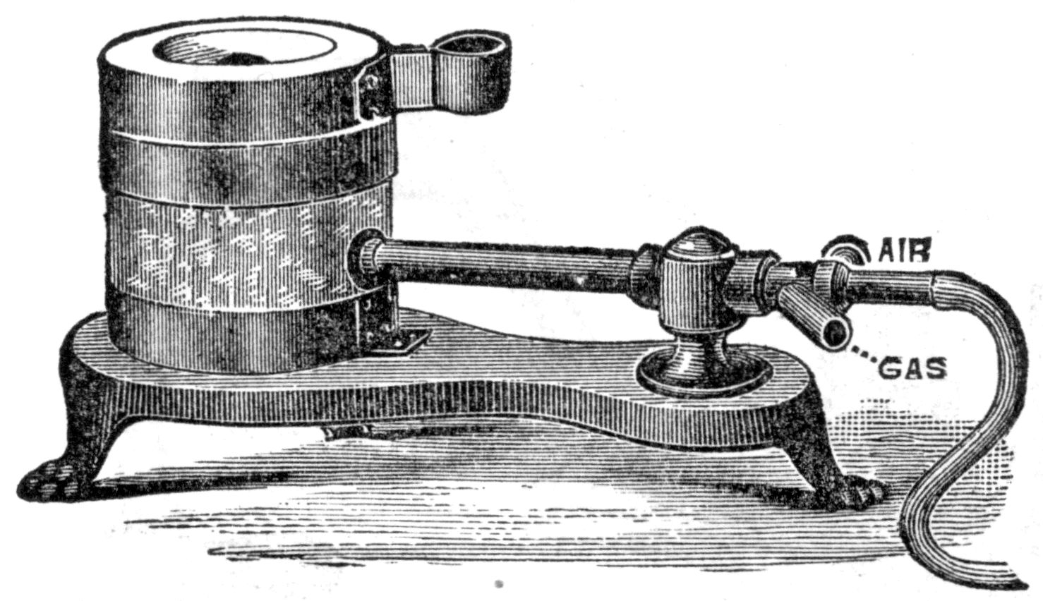
Fig. 55.
Fig. 55 represents a small gas furnace, which is extremely useful for small meltings, experimental work, etc. It consists of a pot made of a mixture of fire clay and asbestos, bound with rivetted iron hoops, and having a hole in the side at which the flame enters. A lid pierced by a central hole permits the escape of the products of combustion, and the crucible is placed in the center so that the flame surrounds it. It is worked with gas and a foot blower. Gas from a ⅜-inch supply pipe will work it efficiently. About ten cubic feet of gas per hour is sufficient for most purposes.
The casing holds the heat so perfectly that the most refractory substances can be fused with ease, using a Fletcher foot blower. Half a pound of cast iron requires from seven to twelve minutes for perfect fusion; the time depending on the gas supply and pressure of air from the foot blower. The crucible will hold about ten ounces of gold.
The power which can be obtained is far beyond what is required for most purposes, and is limited only by the fusibility of the crucible and casing.
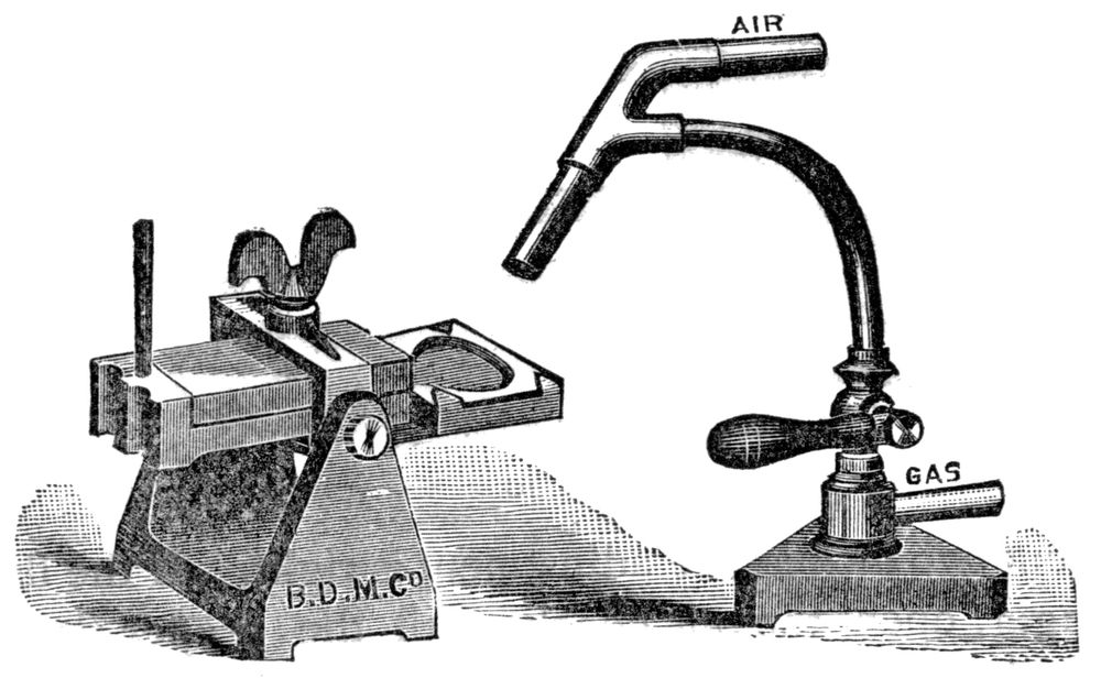
Fig. 56.
Fig. 56 represents a small apparatus, which, owing to its speed and economy of operation, has a very extended use in the jewelry and silversmithing trades. With this apparatus a sound two-ounce ingot of gold or silver can be moulded in two minutes. A crucible of moulded carbon is supported by a sheet-iron slide, or plate, which is clamped to an ingot mould by a clamp which swivels in the U-shaped cast iron stand. The metal to be melted is placed in the crucible, and the flame of the blow-pipe directed on it until it is perfectly fused. The whole is then tilted over by means of the upright handle at the back of the mould. The waste heat serves to make the ingot mould hot. No flux should be used with the carbon crucibles. For the smaller operations, such as making small quantities of colored golds, for electroplating solutions, testing ingots, and the smaller operations of the jeweler and plater, it is invaluable.
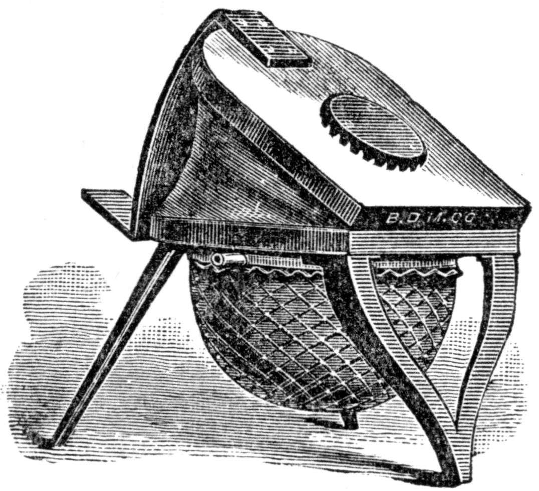
Fig. 57.
The air pressure used in operating gas furnaces varies from one to four pounds per square inch, though the latter is seldom required except for the severest work in large furnaces; as a general rule it is less than two pounds in the operations of the gold and silversmith. The pressure must be arranged so that the air supply equals that of the gas used. This can be readily seen by the color of the flame, as noted in instructions for handling the furnaces. For small operations foot blowers are used. These consist of a powerful bellows having a hemispherical pressure chamber on one side, and adapted to work either by the hand or foot; see Fig. 57.
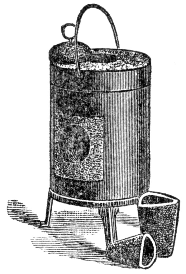
Fig. 58.
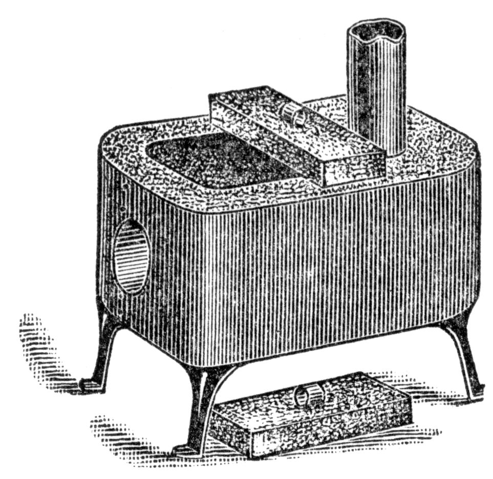
Fig. 59.
The perfect combustion of the gas is secured by mingling equal quantities of gas and air in a mixing chamber, and then igniting the mixture. In the larger furnaces this is accomplished by a mixing chamber placed under the furnace, so as to heat the mixture before ignition, and no pressure supply of air is necessary. In the smaller apparatus, this mixing is done in the burner, which consists of an inner tube carrying an air supply, surrounded by a gas tube, and the whole surmounted by a sliding nozzle for changing the shape of the flame. The mixing chamber being so small, the air and gas pass through it so rapidly that considerable pressure of air must be provided to prevent it from being excluded by the normal pressure of the gas; hence the necessity for a blower when using small burners.
When it is not desirable to use gas, for pecuniary, or other reasons, melting may be carried on by means of a gasoline gas flame, which is noisy, but otherwise little inferior to coal gas. The furnaces for gasoline differ but little in construction from the others, as will be seen by Figs. 58 and 59. The only difference being that the burners are applied from the side and no air pressure tubes are needed, while the furnace is supported on legs to insure safety from fire.
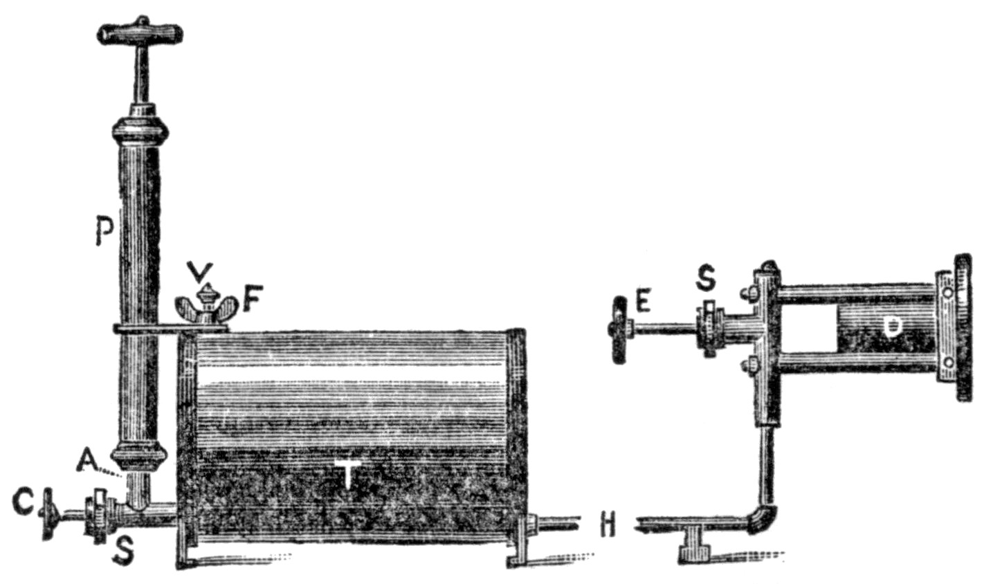
Fig. 60.
The burner for gasoline is radically different from that for gas, being, in fact, a small gas machine, Fig. 60.
In Fig. 60 P is an ordinary force pump, at the bottom of which, at A, is a valve which closes automatically upon releasing the pressure from the pump, C is a check valve which closes the inlet to the tank T completely; F is a filling screw for introducing gasoline. V is a vent screw for letting off the pressure when through; H is a pipe leading from the tank to the burner D; E is the burner regulator, terminating in a fine point, closing the orifice of the burner; S S are packing boxes. Upon opening C and pumping a few strokes a pressure is created in the tank and on top of the fluid, forcing it through the tubes of the burner, which being previously heated, vaporizes the gasoline. This issues from the orifice at the end of E as a highly heated gas and burns as such in the form of a powerful blast, Fig. 61. After being once started the heat of the flame passing through the burner, vaporizes the fluid in the tubes, and hence the apparatus is automatic.
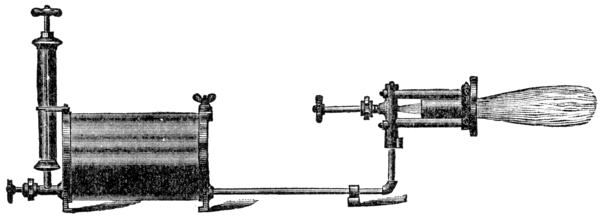
Fig. 61.
The air which is forced in is not consumed, so that to keep up the blast it only requires a few strokes of the pump occasionally to maintain the pressure lessened by the consumption of the fluid.
To operate the blow-pipe: close E; unscrew F, and introduce from two quarts to one gallon of gasoline of 76° according to the capacity of the tank. Replace F and close V; open C one or two turns and give three or four full strokes of pump P, and close C. Heat the burner by burning some of the fluid in a suitable vessel placed under the burner; when hot enough apply a match and open E gradually, until the action is more or less uniform. If no spray or liquid issues from the orifice, the burner is hot enough; if not hot enough, burn slowly until no liquid or spray issues. When sufficiently heated the blast can be made of any intensity desired, by the use of the pump as above. To stop its action, shut the regulator E, or open screw V, or both. When not in use the vent V should invariably be kept open. The mouth of the burner D, should be two or three inches from the inlet of the furnace, or there will not be perfect combustion.
For very high temperatures and muffle work, light the burner as above and heat the inside of the furnace to a bright red; then place the burner against the inlet of the furnace; turn out the burner by means of the cock E, and immediately turn it on again without lighting it, when if the furnace is hot enough, the gas will ignite inside the furnace. The heat can be regulated as in the first method of burning. When burning inside of the furnace, there must be no flame in the burner tube; it should all be inside the furnace, and the tube of the burner must be close to the fire hole, or there will not be enough heat in the tubes.
Use a drop or two of sperm oil on the piston of the pump occasionally, also on leather washer at F, otherwise the apparatus will be apt to leak, corrode and work badly.
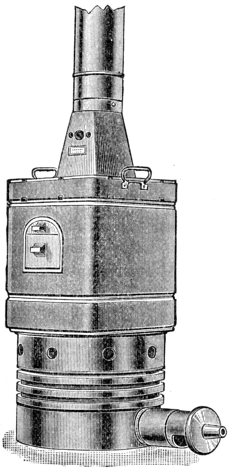
Fig. 62.
251. Muffle Furnace. This consists of a fire-clay furnace, mounted upon a powerful gas burner and containing an oven, also of fire-clay or plumbago, so placed as to receive the full heat of the flame, without permitting the direct action of the flame upon any object placed within it. The objects are placed in and withdrawn from the muffle, or oven, through the door shown in the cut. This door is made of two pieces so that the upper one may be removed to watch the progress of the work without chilling the contents of the muffle by too great an entrance of cold air. They are extensively used for assaying, annealing, etc., and for many other purposes where an exact temperature is required. The illustration shown in Fig. 62, is of a gas muffle, but they are also made to be used with the gasoline burner previously described.
THE LATHE.
252. Of all the tools and machinery employed by the watchmaker, the lathe is the most important. Very poor work is often turned out by those possessing a first-class lathe, but there are very few persons who can turn out good, true work, from a poor, cheap lathe, and if it is untrue it is utterly impossible to turn out good work. Wonders can be accomplished by the ingenious mechanic who thoroughly understands the capabilities of the lathe. By patient skill of manipulation, the Chinese and Japanese turn out some truly wonderful work; they succeed in turning sphere after sphere, one inside the other, from a solid piece of ivory, the opening from one to another being comparatively small.
The earliest form of the lathe in the trade was the dead center: that is, a lathe whose parts did not revolve, the object to be operated on being placed between centers and made to revolve by means of the bow. This form of lathe was succeeded by the live spindle or live mandril pattern, although there were many good points about it that must be acknowledged. It contained one great element that many modern appliances, termed lathes, lack, i. e., the element of truth. No matter how coarsely or crudely constructed, this truth was not eliminated, except by the ignorance of the artisan, for the centers must remain the same relatively, whatever may be their position in relation to the lathe bed.
With the introduction of the live spindle lathe in this country, the verge, Jacot and other lathes and tools of that type were rapidly abandoned. In Europe, however, the live spindle lathe did not meet with such a cordial reception, and it has taken many years, in some localities, to overcome the prejudice against them; in fact, there are still many workmen there who cling to the dead center patterns.
The all-important point in lathes of the live spindle type is accuracy of fitting, and particularly in regard to the spindle and its bearings, for unless a certain degree of perfection is attainable in this particular, it is worse than useless, as it not only does not do the work, but leads the artisan astray. The workman, sometimes, through motives of economy, purchases foreign made lathes, that closely resemble the American in outline and finish. These lathes, as a usual thing, are not accurate, and in the greater majority of cases the chucks which accompany them are worse than nothing, and yet these lathes, in nearly all cases, are declared to be as good as the American. There are some foreign lathes that are very carefully made, and are quite as true as the best American, but they are the exception and not the rule. The workman who buys one of these lathes cannot, of course, tell whether it is right or wrong until he has placed it on his bench and tested it, and even then he cannot be sure, for although when a certain chuck is placed in the spindle and tested it may apparently show no deviation from truth, there may still be untruth in the spindle or chuck or both, as the errors in one may be counteracting the errors in the other, and if the chuck be turned or an absolutely true chuck placed in the spindle, the error will be made quite apparent. If an American lathe, by any possibility, is allowed to pass the inspector, and finds its way upon the market, the maker is only too glad to replace it with a perfect one, for his reputation is at stake; but if one of the imitation pattern proves untrue you will have to do the best you can.
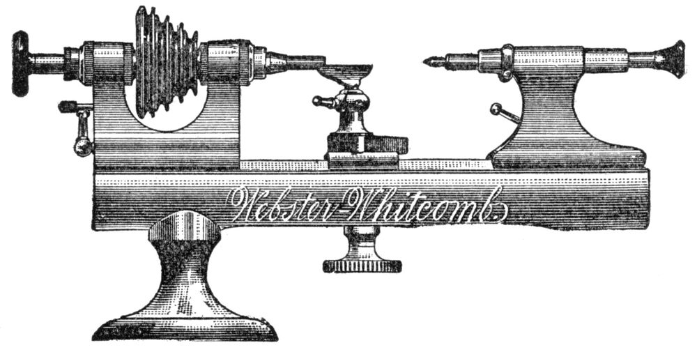
Fig. 63.
There are American made lathes upon the market that are as inferior in many respects as the imitations, and the watchmaker will do well to do without a lathe until such time as he can afford to purchase one of known reputation. Among the first-class American lathes upon the market may be mentioned the Webster-Whitcomb, shown in Fig. 63; the Moseley, shown in Fig. 64; the Hopkins, shown in Fig. 65, and the Rivett, shown in Fig. 66, and others.
An excellent lathe for the heavier work of watchmakers and jewelers, such as cannot be performed with satisfaction on the watchmaker’s lathe, is the No. 4 Barnes, which is shown in Fig. 67.
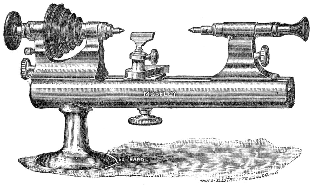
Fig. 64.
For screw-cutting, the manufacture of watchmaker’s tools, fishing reels, repairs on tower clocks, in fact, all the heavier work of the trade, it is admirably fitted.
253. Care of the Lathe. The American lathe of to-day is a marvel of completeness in its parts, and how many hours, yea months, of study and experiment have been bestowed upon it by its projectors and makers to acquire these points of utility and excellency? What a vast amount of care has been exercised for the production of a perfect lathe! Must this care cease at the moment it passes into the hands of the watchmaker?
It is a very easy matter at any time to wipe off the dust and oil that may accumulate, but does this alone constitute due care? There may be a nice glass case to cover it and keep off the dust, and a very good idea it is, if faithfully used; but if a counter shaft is on the bench, or much lathe work is to be done, it soon falls into blissful desuetude, or finishes its usefulness by being broken. Then, often, a cloth is wrapped about the lathe, which soon gets soiled and looks badly, let alone the poor protection it affords.
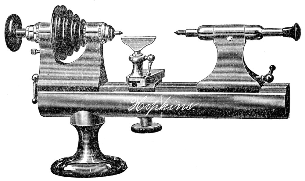
Fig. 65.
Dust is omnipresent, and the greatest enemy to all active machinery; it insidiously makes its way into every crease and crevice, and if not promptly removed will cause untold damage. We cannot get rid of it and must (like the industrious housewife) wage a constant warfare against it.
The care necessary to be given to a fine lathe differs from most other tools; it is not confined alone to the removal of dust and keeping clean, but the fitting properly of the several parts as used. There should be no overstraining when tightening screws, chucks, etc., or when fitting articles in both wire and wheel chucks, and so on through the list.
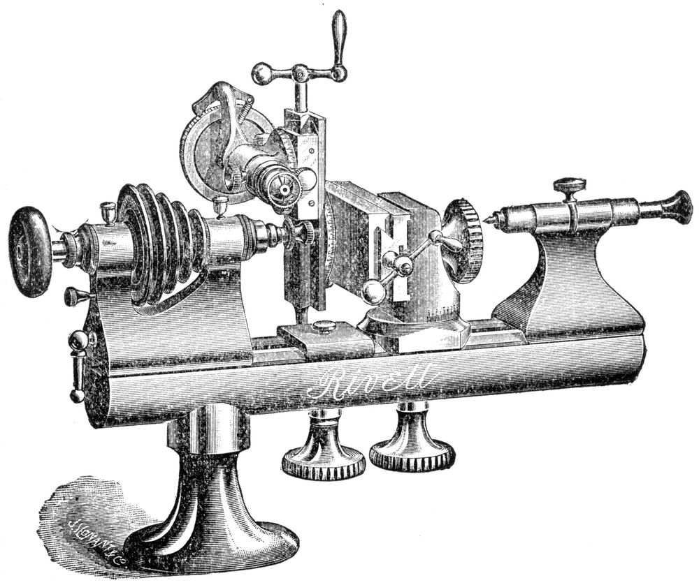
Fig. 66.
The face of the lathe bed when it comes from the makers is (or should be) perfectly true from end to end, in order that head and tail stocks will meet on a direct line of centers, even should they be changed end for end, and a good lathe will meet those requirements. Now, it is obvious to any thinking mind that if this face becomes injured by neglect, whereby the nickeling is removed in spots or portions, they will, in all probability, become rusty; this rust will then eat away and throw off more, and soon the face presents an uneven surface, which will tend to destroy the line of centers between head and tail stocks.
The head stock, usually occupying one position, causes less wear at this point or place, while the hand-rest and tail stock are constantly being shifted, so where there is more motion or action there must be more wear, especially if dust, chips, or grit be allowed to accumulate beneath them, and though the wear is seemingly imperceptible, it nevertheless is there, and will sooner or later manifest itself, and this is a signal that the level of the bed is becoming impaired, and, necessarily, the truth. Thus too much care and attention cannot be exercised in guarding against chips and dust when sliding hand-rest back and forth on the bed.
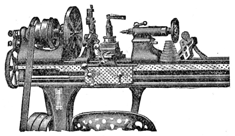
Fig. 67.
At the end of the bed, where the tail stock takes position, many watchmakers have the tail stock off, and this portion is more exposed to atmospheric action, also receiving perspiration from the hands when they come in contact. Again, others let the tail stock remain in position, only removing when it comes in the way. In the former case, it is well to devise some means for the protection of the bed; this is easily done by making a sheath of chamois skin to slip tightly over the bed; it can be removed and replaced readily, and when it becomes soiled, can be washed.
This sheath should be fully two-thirds the length of bed, or reaching from tail end up to hand-rest when it is close to head stock. It preserves the bed from dampness, which is considerable in some climates, also the perspiration of the hand and flying chips and dust. In the second case, if the tail stock is allowed to remain on the lathe, or, if removed and placed on the bench, it is subjected to all the evils the bed is in the former. Our opinion is, the tail stock should be kept in its compartment in a tight-fitting drawer, away from dust and accidental knocks of other tools on the bench; the tail spindle not being nickeled, is more liable to rust if left exposed, and should be kept in a sheath of oiled paper. This may seem superfluous and too much bother, yet it is taking proper care which tells in the end.
The bottom of tail stock should always be brushed off before placing in position, not only for its protection, but for fear some particle of grit may be adhering, thereby throwing it out of truth, and screwing it down tight only adds injury to the lathe if allowed to remain.
The head stock demands close attention; the spindle should run freely without end-shake, and about once a week should be speeded, meanwhile administering oil until it leaves the bearings clean, and then wiped off. A little oil should be added every day. See that the mouth of the spindle is kept bright and clean; thrust a piece of cloth clear through spindle every now and then, that all dust and dirt may be removed.
Wire and wheel chucks should often be washed in gasoline to remove gummy dirt and oil which is constantly adhering, and it is even well each time a chuck is used, to wash off first, then wipe dry. A little dirt on the mouth of spindle, or on the chuck, often throws it out of truth, and consequently the article fastened therein also.
When fitting head or tail stocks, or in fact any attachment, do so carefully. Do not bang it in place as if you held a grudge against it, and when in position see that they are tightly screwed in place.
Having too much end-shake on live spindle, especially in soft lathes, causes uneven wear in its bearings, besides not being reliable for true pivoting or any such work.
When the cost of a lathe is taken into consideration, it goes to prove that it is not easily replaced. Where is the jeweler with a stock of goods who would retire without first seeing that his valuables were in the safe, but how many are there that think of giving this protection to their lathes? Some do, but the greater per cent do not. It is a good plan to see that the head stock, the tail stock, and attachments are in the safe and should a fire break out that endangers the store, and no chance to save it, the feeling of satisfaction is great to know the lathe is safe, that is, the most expensive parts, for the bed can be purchased at a nominal cost compared to the attachments.
THE FOOT WHEEL.
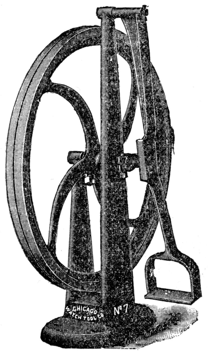
Fig. 68.
254. In the selection of a foot-wheel the workman must be governed by his own experience and taste, for the variety that exactly suits one person is very distasteful to another. The swing treadle pattern shown in Fig. 68 is a very popular one with American workmen. These swing treadles are made in various ways by the different manufacturers, but the methods of using them are alike. There are workmen, however, who prefer the heel and toe motion and others that prefer the up and down motion. This is all a matter of taste and it matters but little what form of lathe wheel is used provided the motion is steady and the exertion is light. As a general rule a heavy wheel, say forty pounds in weight, will be found, on the whole, much better than a light one and the motion will be more uniform.
255. Driving Bands and Belts. Most foot-wheels are so constructed that either a flat or round belt may be used in transmitting the power to the countershaft or lathe, as the case may be. Many watchmakers use a flat belt between foot-wheel and countershaft and a round leather belt, or cord, between countershaft and lathe. If we may judge by appearances, this is the favorite fitting. Others use round leather belts in both instances, while others again use cotton or hemp cord or gut. All things considered, the round leather belt seems to possess advantages over all others. It does not slip as easily as cotton cord, is more elastic than gut and throws less strain on the bearings, absorbs less power and works much smoother. The ends are fastened together by means of an S hook and the cord may be readily tightened by giving it an additional twist or two.
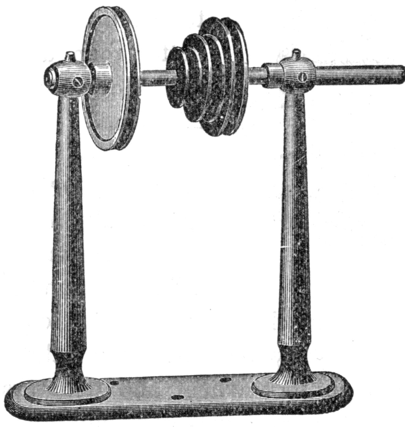
Fig. 69.
256. The Countershaft. The countershaft is indispensable in using milling tools, wheel cutters and pivot polishers. The pattern shown in Fig. 69 is but one of many on the market.
In some of the patterns the uprights extend through the top of the bench and are held securely in place by means of thumb screws or wing nuts. The pattern shown in the illustration is mounted on a solid metal base which is intended to be fastened to the bench by means of screws. The advantages of using a countershaft are three fold: First, you are able to regulate your speed perfectly without changing the motion of the foot from fast to slow or vice versa; second, your belt is carried to the back of the bench, where it is out of the way, instead of coming down in front of the head; and third, you obviate the necessity of having holes in your bench on each side of the lathe, that small articles are liable to drop through. Fig. 70 illustrates the favorite arrangement of foot wheel, countershaft and belts.
THE BENCH.
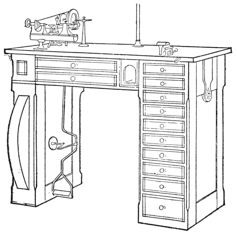
Fig. 70.
257. As previously suggested (230) it is of the utmost importance in doing good work, and doing it rapidly, that your bench be kept orderly and clean at all times, and that all your tools and devices be in their proper places, exactly where you can put your hand on them at a moment’s notice. An excellent arrangement for a watchmaker’s bench is shown in Fig. 70. This bench was designed by G. W. Laughlin, and is complete in every detail. Benches can be purchased ready made from material dealers, both with and without curtain tops, but there are many watchmakers that prefer to make, or have made for them, a bench varying from the usual pattern. The bench illustrated is made of black walnut, veneered with French walnut and bird’s eye maple. The top is 21 inches wide by 41 long and is 33 inches from the floor. The drawers on the right-hand side are 10 inches wide. In the center are two shallow drawers, while the left-hand side is entirely boxed in.
IDLERS.
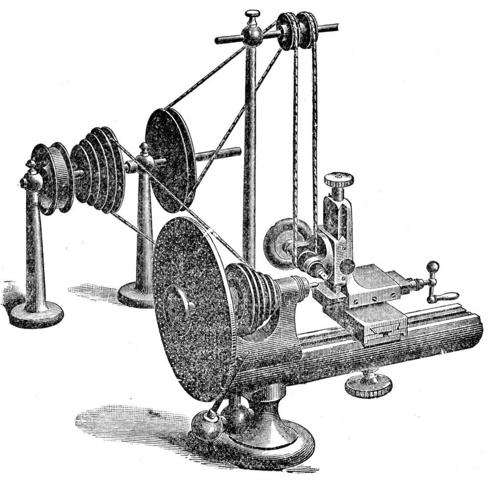
Fig. 71.
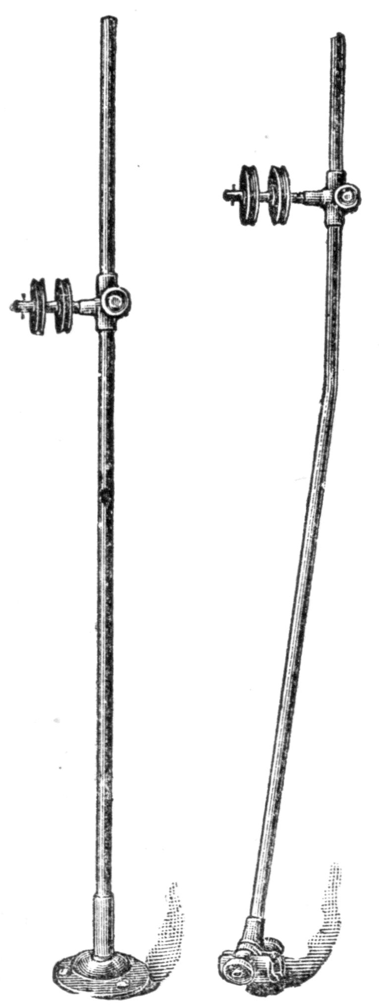
Fig. 72.
Fig. 73.
258. Idlers are especially valuable for use on slide rest tools, such as pivot polishers, milling attachments, wheel cutters, etc., and with traverse spindle tailstocks, traverse spindle drivers, etc., to give a vertical direction to the belts. Idlers are constructed in various forms, some of them being mounted on upright posts, fastened to the bench just back of the lathe, as shown in Fig. 71; others consist of steel rods terminating in a ball, and socket joint, where it is fastened to the bench, as shown in Fig. 72, while in other patterns the rod is fastened by means of a wing nut to a brace running from one to the other of the supports of the countershaft and may be placed at any desired angle. The idler shown in Fig. 73 can be used in this way. Some watchmakers prefer to place their idlers on an overhead countershaft, which is usually fastened just back of the bench and about two and a half or three feet above it. The idler shown in Fig. 72 can be screwed to the bench or to the wall above the bench, in the latter case it will extend out horizontally over the lathe and is out of the way of the watchmaker when not in use. In the forms shown in Fig. 71, 72 and 73 the belt passes from the countershaft over the idler and one long belt only is used. This style is sometimes varied by using two separate belts one from the countershaft to the idler and another from the idler down to the lathe. If in the latter style, a cone pulley of rubber is used on the countershaft and also for the corresponding pulley on the idler and a plain pulley for the down belt. Of course in this form the idler stand must be in the form of a countershaft, as the pulley must be fast on the shaft and the shaft itself must revolve. In the styles shown above, the shaft is rigid and the pulleys revolve upon it. The advantage of using the cone pulley style is that the speed of the cutter or other attachment may be varied at will without in any way increasing or decreasing the speed of the wheel.
CHUCKS.

Fig. 74.
Fig. 75.
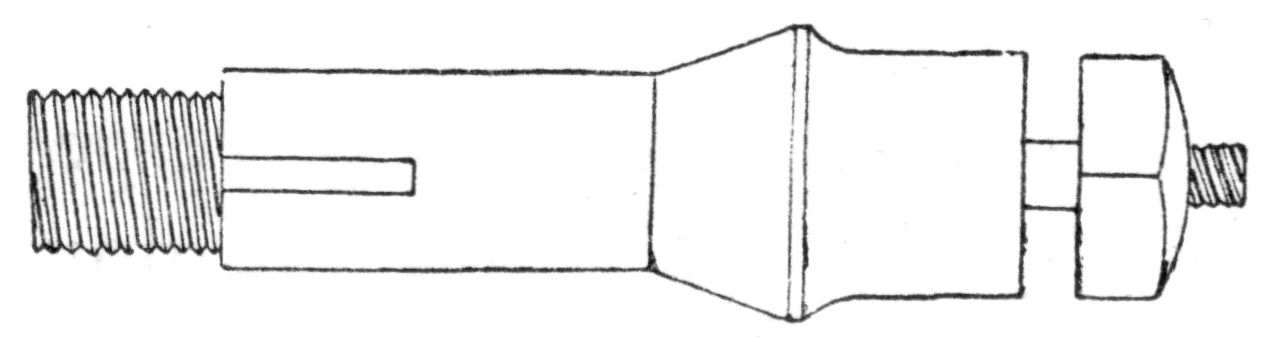
Fig. 76.

Fig. 77.
Fig. 78.
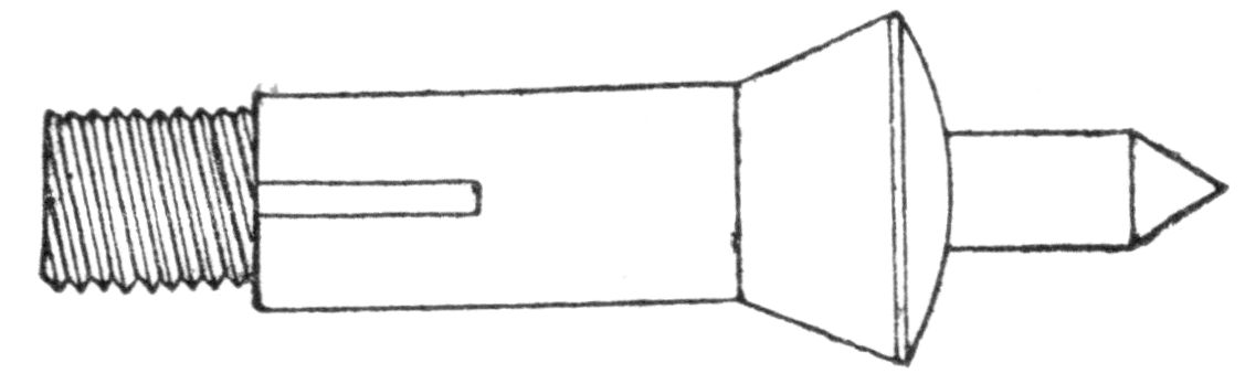
Fig. 79.
259. True chucks are the most important adjuncts to a watchmaker’s outfit. A true lathe with poor, untrue chucks is almost useless. Chucks hold the work truest that comes the nearest to fitting the holes in them. If you try to hold work in a chuck that is too large or too small, you will soon get the chucks out of true and you will soon become dissatisfied with your chucks, your work and your lathe. Care should always be taken to select a chuck that will take the work without straining it open and yet is not so large that undue pressure will have to be used in holding it. The American split chuck, when true, will hold almost any piece of work with the greatest precision as regards truth; but the split chuck is a delicate attachment and will not stand hard knocks and rough treatment. After using them, you should clean them in benzine to remove all dirt, rinsing them in alcohol and drying with a soft linen rag, and see that no small chips of metal are left in the openings that may throw the work out of truth the next time they are used. Fig. 74 illustrates the regular pattern split chucks that accompany American lathes. Fig. 75 is a conoidal wire chuck, so called because the shape of the mouth of the chuck is conoidal in lieu of the shoulder usually left on wire chucks for the bend in the spindle. Fig. 76 is an arbor chuck. This is a solid chuck on the end of which is a threaded arbor for the reception of saws, laps, wheels, etc., which are held firmly in position by means of the nut on the threaded arbor. Fig. 77 is a screw chuck. This is a solid steel chuck having a threaded hole in the end for the reception of cement brasses, etc. Fig. 78 is a shoulder chuck. It is a split chuck with a large opening in the end with square shoulders for the work to rest upon. Fig. 79 is a taper chuck, which is solid and has a large opening for the reception of tapers, centers, laps, etc. Fig. 80 is a step or wheel chuck, which usually comes in sets of five, and as each chuck has nine steps, a set of them will accommodate forty-five different sizes of work. These chucks are useful for holding mainspring barrels when fitting in the cap, should it become out of true; for trueing up the barrel of English lever watches that are damaged by the breaking of a mainspring and for holding almost any wheel in a watch, such as the fitting of a center wheel to a pinion, or in making sure that hole in the wheel is in the center. These chucks will the hold wheels from 5 to 2.25. The chucks mentioned above are the most common ones in every day use and usually accompany the American lathe in combination sets. As intimated, these chucks are delicate and as a usual thing they do not receive the care they should, when their cost and the delicate exactitude demanded of them is considered. The watchmaker who prides himself on his good work and the orderly condition of his tools, attachments and bench generally will purchase or make for himself a nice chuck box with a glass or wooden cover to exclude all dust and flying chips. You cannot expect to do good true work with a chuck that is thrown carelessly into a drawer containing an assortment of files, a hammer, staking block, oilstone, screw driver, sliding tongs, etc., and yet how many watchmakers take just this kind of care of their chucks, and complain of their untruth, and declare that a wax chuck is the only thing that can be absolutely relied upon for truth. Fig. 81 illustrates a neatly arranged chuck box made by the Faneuil Watch Tool Company. In it all the various chucks may be arranged and the whole may be covered with a glass shade to keep out all dirt. A wooden cover might be used and perhaps would be preferable to many as it is less liable to be broken and occupies less space and therefore admits of the box being placed in a drawer, leaving more room on the bench for the necessary tools and attachments.
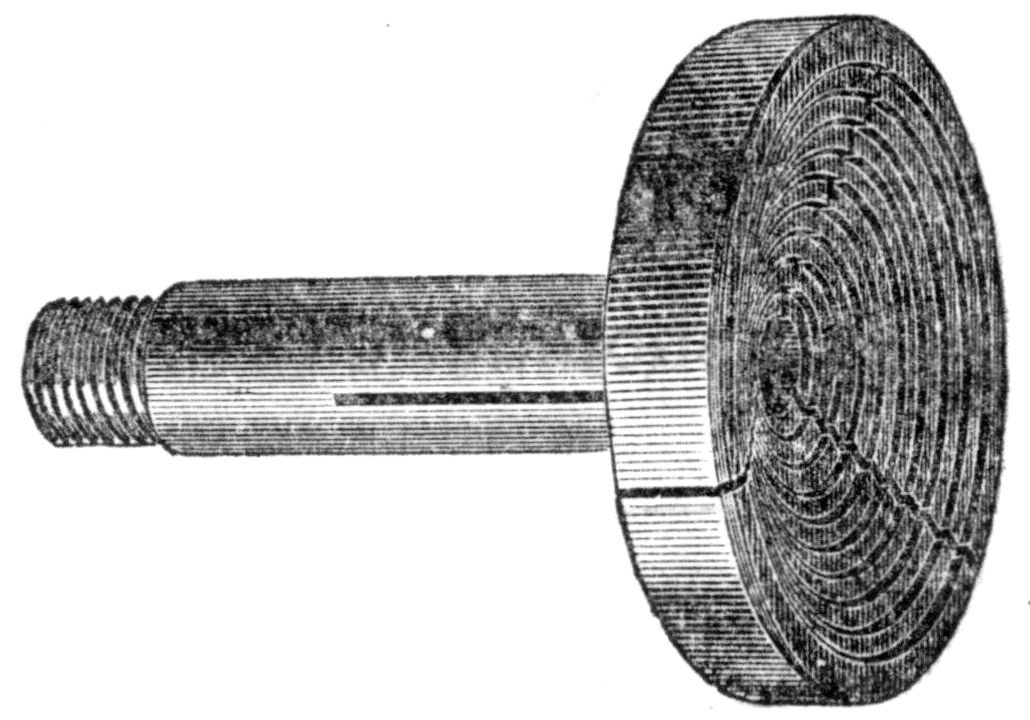
Fig. 80.
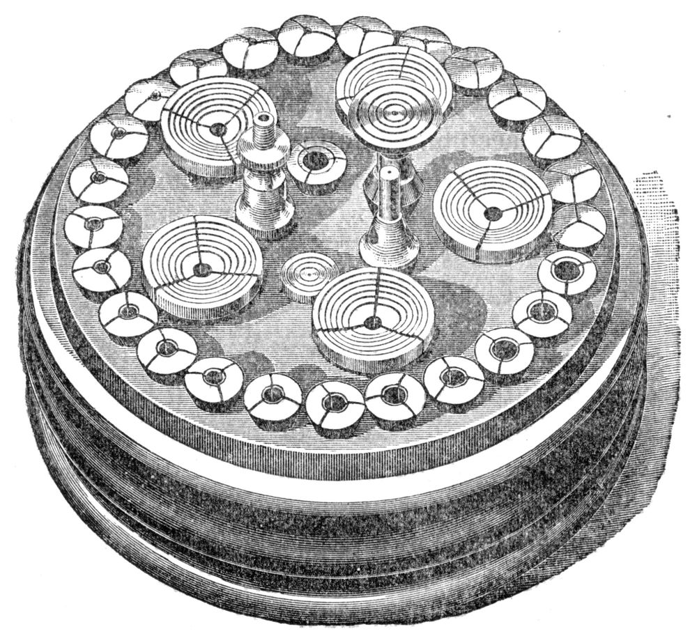
Fig. 81.
A chuck box should be well soaked in oil so that the wood will absorb no moisture and thus tend to rust the chucks. A small envelope made of tissue paper and filled with quicklime will, if placed in the chuck box, take up the moisture in the air and prevent the chucks from rusting.

Fig. 82.
260. The chuck stepping device, invented and patented by Mr. Moseley, is a valuable attachment for the lathe. In this device, shown in Fig. 82, a rests in chuck slightly less than diameter of work; b tightens in rear end of draw-in spindle, and turning c regulates the depth of step. By the use of this tool any wire chuck will accurately serve as a step chuck. It is a device of great service to the watchmaker when used and understood. It enables him to make a step in any wire chuck of any depth he may desire, and will push out the work at any time when he so desires. It is very useful many times for a stop for marking or cutting off when you want a number of pieces of the same length or kind. Many object to the stepped chuck for general use.
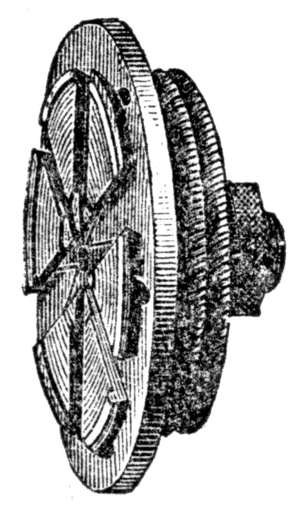
Fig. 83.
261. In addition to the regular chucks which usually accompany American lathe combinations may be mentioned some others which from time to time have been placed upon the market by manufacturers of watchmakers’ tools. These chucks were devised for holding work which it was found in practice could not be held by the ordinary chucks.
262. The bezel chuck, shown in Fig. 83, was originally made with a view of holding bezels only, but is now made so that it will hold watch plates, coins, etc., and is adjustable to any size. It can be fitted to any lathe and it requires but very little practice to use it, as it is extremely simple and any one who uses a lathe can make or repair bezels in a workmanlike manner. It holds the work as in a vise, and no amount of turning or jarring will loosen the jaws, while it may be opened or closed instantly by simply turning the milled nut behind the face plate, thus enabling the operator to turn and fit a bezel perfectly, by trying on the case as many times as necessary. It holds the bezel by either groove, so that the recess may be turned out when too shallow or too small for the glass, or the bezel may be inverted and turned down when it rests too hard against the dial. It will be found especially useful in turning out the inevitable lump of solder from the recess of the bezel after soldering, and in fitting to case, as the process of soldering generally makes the bezel shorter, and consequently it will not fit the case. It also renders the operation of polishing bezels, after soldering, the work of but a few moments. In turning out the recess for glass in bezels, especially those of the heavy nickel variety, it will prove a friend indeed. When, for instance, you look through your stock of flat glasses and find none to fit, but have one that is just too large. Any watchmaker knows that if the groove in the bezel is imperfect, it is very apt to break the glass. This chuck is also useful as a barrel closer, holding work while engraving, and many other uses that will present themselves to the watchmaker.
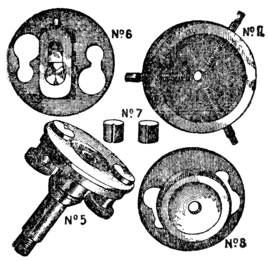
Fig. 84.
263. The Hopkins’ patent adjustable chuck, shown in Fig. 84, is designed to grip and hold firmly and accurately any size of work, from the smallest staff to the largest pinion, watch wheels of all sizes, mainspring barrels and other large work, and can be adjusted to any make of lathe, by simply placing it friction tight on a plug chuck fitted properly to the lathe. In using this chuck for staffs, pinions, wire, etc., fasten a V-piece, 7, of proper size, in the hole of attachment 6, taking care that both the V and the seat in which it rests, are free from chips, dirt, etc. Then lay your work in the V and fasten it there by means of the sliding jaw above it. This done, place the attachment on the face of the chuck body, with the disc slipped under the heads of the two spring bolts, and then spin the work to center the same as when using wax. After centering thus, fasten the disc to place by tightening the nuts on the back ends of the spring bolts. For holding work by the web of the wheel, place the wheel under the screw cap, on the face attachment 8, and screw the cap down firmly on it, with the staff or pinion projecting outward through the center hole. This done, proceed the same as when using attachment 6. For mainspring barrels and like work, use attachment 11, and place a bit of broken mainspring between the work and the ends of the three binding screws, and tighten the screws down on this instead of directly on the work.
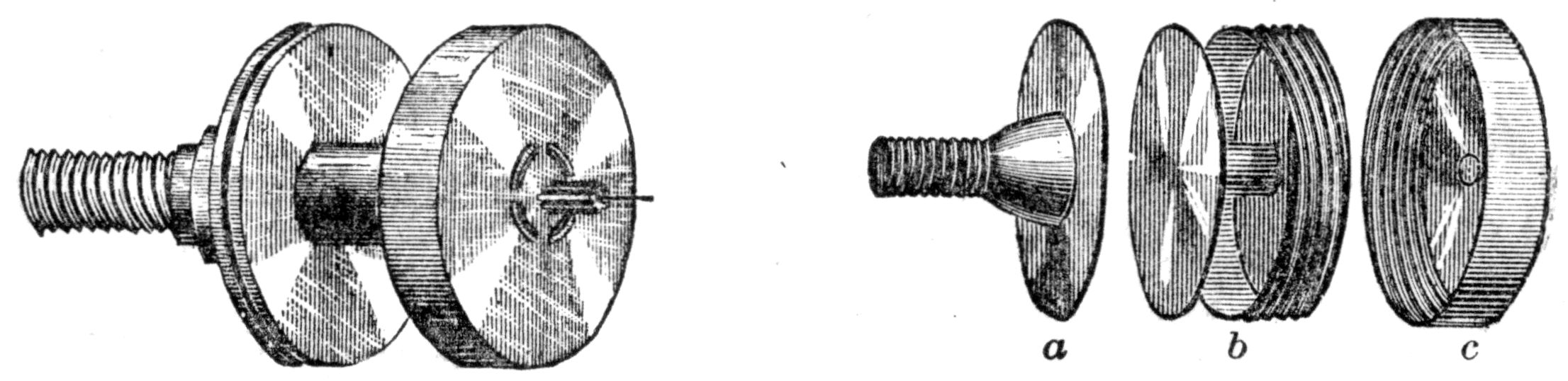
Fig. 85.
Fig. 86.
264. The Spickerman patent cement chuck, shown in Figs. 85 and 86, holds and centers accurately any wheel in a watch while drilling, polishing or fitting new staffs or pinions, and all danger of injuring the wheels is obviated. It will fit all kinds of American or Swiss lathes. The holder shown in Fig. 86 at a, is turned down to nearly the size of the screw for the lathe, and the screw is cut so the holder will set as close as possible to the lathe. The face of the holder is then turned perfectly true. Put the wheel to be centered in cap c, as near to the center as convenient, and then screw on b. Then place the cemented face of chuck b against the face of holder a on the lathe, and with a lamp warm the cement between the surfaces, holding the chuck by means of a pegwood against the pivot of the wheel in the cap c, and it will move to an exact center as soon as warmed sufficiently. New cement should be added occasionally between the surfaces, as the old cement hardens and burns away, and does not center as well as when new. Fig. 85 shows chuck with wheel inside ready for centering and drilling.
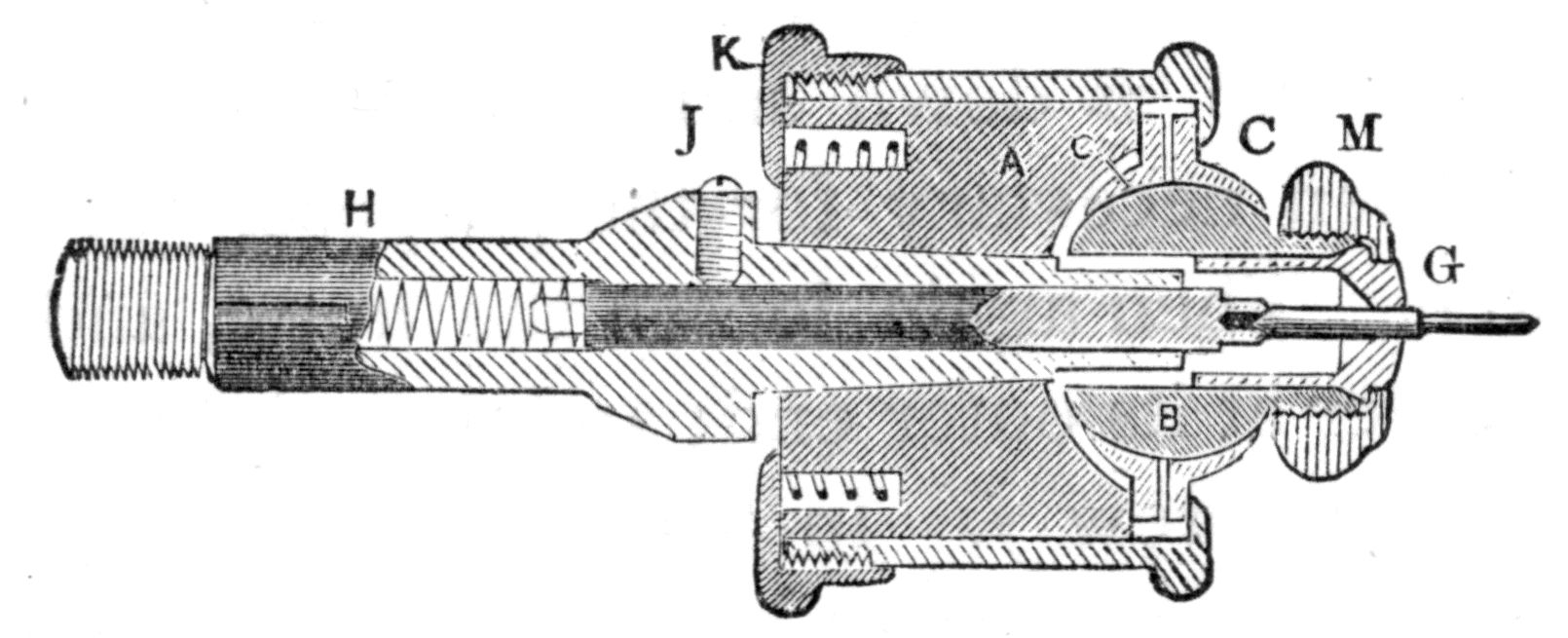
Fig. 87.
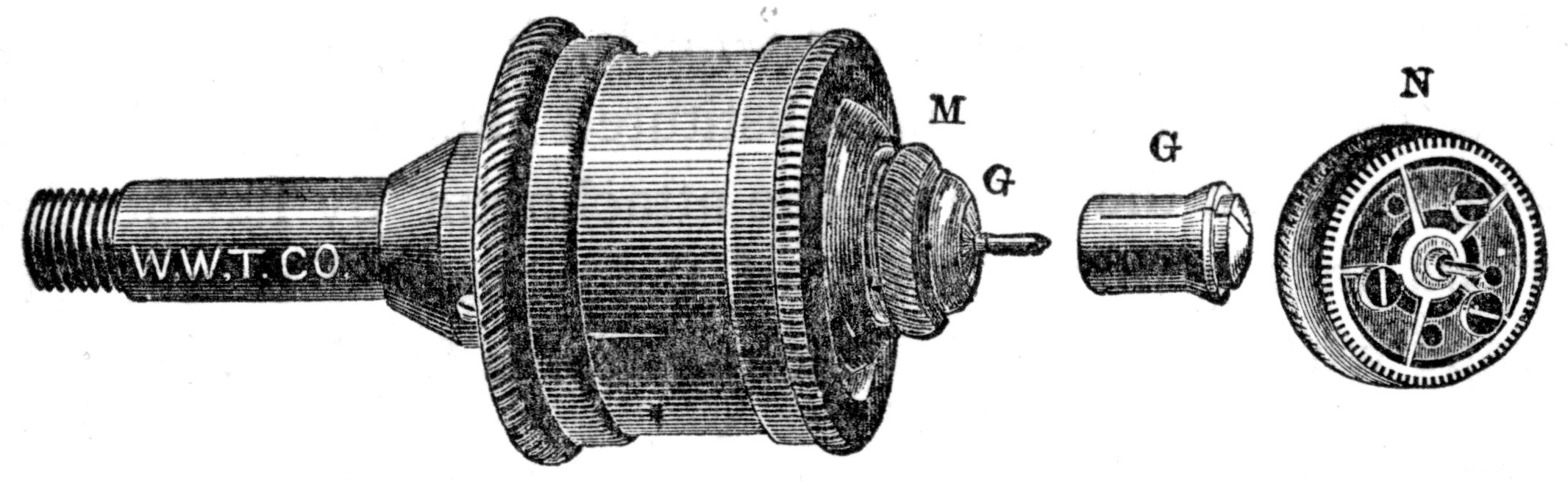
Fig. 88.
265. The gem patent pivoting chuck, shown in Figs. 87 and 88, is intended as a substitute for wax when performing pivoting and like work. By the means of the ball b, placed between the two sliding sockets c, c, with the several other parts as represented in Fig. 87, a combination of sliding and ball and socket movements, in connection with a spring pump-center is obtained. A set of ten or more supplementary chucks g, with different sizes of center holes, and attachment n for all sizes of wheels, are furnished with each chuck. The supplementary chuck g, in the form of a small split chuck, is made to fit into a hole with taper mouth, in the center of the ball b, and is drawn into place and the work fastened firmly in it by means of the binding nut m, which screws on to a projection extending outward from the front of the ball. To use this chuck, proceed as follows: Remove the nut m, and give freedom to the working parts by loosening the large back nut k. Then to bring the hole through the ball b into line, spin the ball to center, first at the base of the projecting screw and then at the mouth of the hole through it, and in this position again fasten the parts, by tightening the nut k. Then give freedom to the pump-center by slightly loosening the set screw j. When doing this, hold your finger against the front of the chuck, to prevent the center rod from shooting out of its place when freed. Then having placed a supplementary chuck g, of proper size, in its place in the chuck, and your work in it, with its back end resting properly in the countersink in the end of the pump-center, fasten it there by screwing the cap m down snugly over it, using a small lever pin when necessary for the purpose, but not with undue force. Then again loosen the nut k, and spin the work to center at its outer end; and then tighten both the nut k and set screw j. In tightening the set screw j, make sure it is so tightened as to prevent the pump-center from slipping from place when working. If from tightening the screw j, it is found that the work has been thrown in any degree away from true center, loosen the nut k, leaving the pump-center fast, and again spin to center and fasten as before. After a little practice this can all be done in a few seconds, and the work brought to absolute center.
In using attachment n, for wheels, the nut m and chuck g are removed, and n is substituted therefor; the work being held on the face of the attachment by flat-headed screws that grip the arms of the wheel. For cylinder escape wheels a special attachment n is furnished.
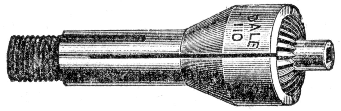
Fig. 89.
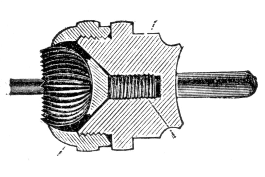
Fig. 90.
266. Fig. 89 illustrates a crown chuck, which is used for holding crowns while undergoing repairs. The Dale chuck shown in Fig. 89 is made on the lines of the ordinary split wire chuck, a large recess being turned in the end for the reception of the crown. The Johanson chuck is illustrated in Fig. 90, and is quite different in construction, a ball-shaped cap with right hand thread screwing down onto the body of the chuck, thus holding the crown from the outside, while a screw-center with left hand thread, holds it firmly from the inside. This chuck is made in two patterns, one for use in a No. 40 wire chuck, as shown in Fig. 90, and the other is mounted on a regular chuck and is ready to insert into the lathe-head the same as an ordinary wire chuck.
THE SLIDE REST.
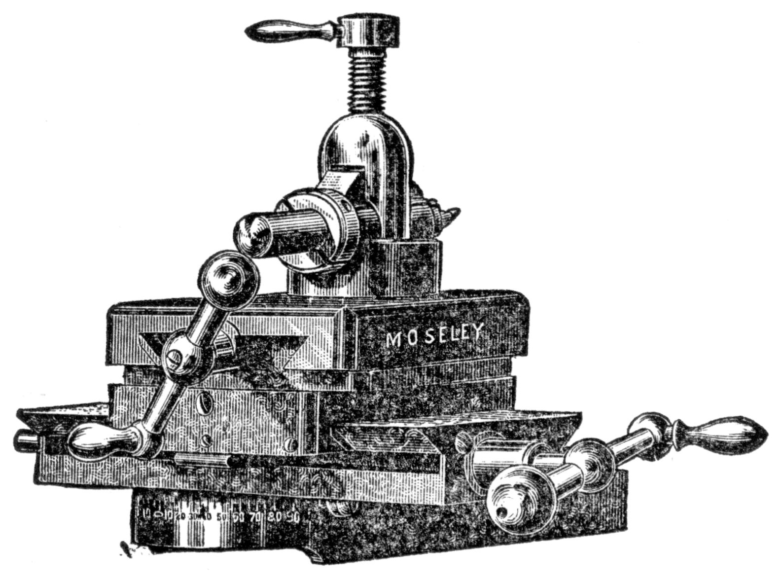
Fig. 91.
267. The slide rest is an expensive but very useful adjunct to the lathe. It is used so extensively in this country, however, that a full description of it seems superfluous. Fig. 91 is a fair example of a modern slide rest for the American lathe. The tool-holder varies with the different makers, but the rests proper are all made on the same general principles, that of two sliding beds working at right angles to each other, and carrying a tool-holder, capable of being raised or lowered or set at any desired angle.
268. Brass is easily turned with the slide-rest in an ordinary lathe arranged for the purpose, but the turning of steel demands more care in setting the cutter so as to obtain the best cutting edge as well as in determining the point of application of the tool. Preliminary trials must be made, and the following remarks will be of service as a guide.
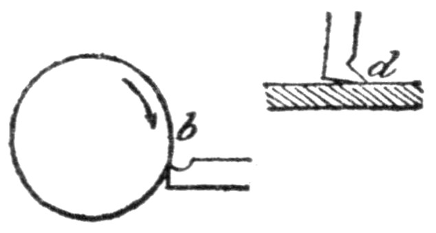
Fig. 92.
269. Engineers use a hooked tool to a very great extent for both planing and turning. Both experience and reasoning point to the conclusion that a tool of the form b or d Fig. 92, possesses many recommendations, and numerous designs of hooked tools more or less resembling these figures are employed with advantage; the tool occupies the best possible position in reference to the surface it is required to cut, and the cutting edge is both sharp and solid. It will be evident that a certain relation exists between the cutting angle and the point of application of the tool to the cylindrical object that is being turned, and this it is necessary to determine. With a hooked tool, as with the ordinary slide-rest cutter, a cutting angle which is too acute will wear away rapidly; when too obtuse, the tool scrapes and will only act when considerable pressure is applied.
In conclusion, it is clear that in forming or re-grinding any tool for cutting a surface, it must be so arranged that its edge makes the least possible angle with the surface that is consistent with the securing of a sufficient degree of resistance to the cohesion and the hardness of metal operated upon; in other words, the end of the tool must be almost tangential to the circumference of the object, and the angle of the cutting edge must be obtained by removing metal from the top face of the tool. These principles are applicable to all tools for metals; to the blades of drills as well as to the cutting edges of gravers, etc.
270. The angle of the cutting edge of the tool used in the slide rest for steel should be less than that employed for operating on brass. According to Holtzapffel, it may vary in the former case from 60° to 80° and, in the latter case, 70° to 90°, according as the tool is required for rough turning or finishing. 60° and 80° may, however, be taken as convenient angles in the cases respectively. Simple methods of ensuring that the cutting edge has any required angle are described in article 396.
The velocity with which the lathe revolves should also be less when turning steel, and care must be taken that both the tool and object are constantly moistened with oil.
It is sometimes desirable to arrange a small dropping-can for the purpose of keeping up the supply; this may be easily done by placing a can containing the fluid above the level of the work and allowing a piece of lamp-wick, previously moistened, to hang from it so as to almost touch the work: a continuous series of drops will fall, owing to the influence of capillarity.
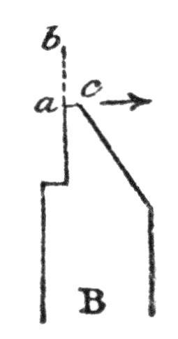
Fig. 93.
271. When roughing out work it is best that the cutter first travel perpendicular to the object, from a towards b, Fig. 93, and then in the direction of the arrow. The corner a should only be used for finishing an internal angle or for roughing it out, and, in this latter case, the cutter must advance along a b and be withdrawn from the metal in the direction of the arrow. The small face at the end, a c, should be narrow.
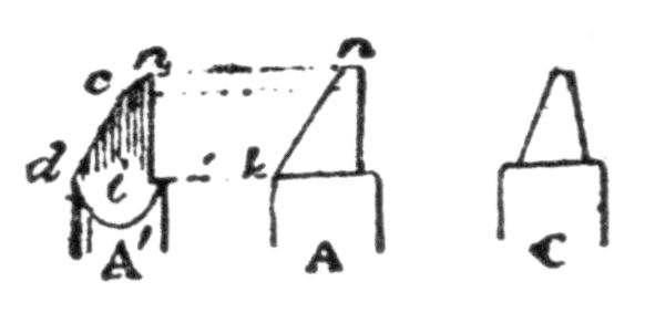
Fig. 94.
272. Forms of slide-rest cutters. The usual forms of cutters for use in the slide-rest are shown in Figs. 94 and 95. A and A′ are respectively the plan and side view of the most common form. Two inclined planes i n and d c are formed on the left-hand and under sides. The point on which they terminate is cut off square, a cutting edge, which is more or less acute according to the metal to be operated upon, being obtained by a third incline c n. The width of the square cutting edge, indicated at n in figure A, varies according to the metal to be operated upon, as well as this incline c n. It is advisable to be provided with at least half-a-dozen cutters of this form, with edges of varying width and inclination, and even this number is often found insufficient; cutters for steel should never be used in turning brass.
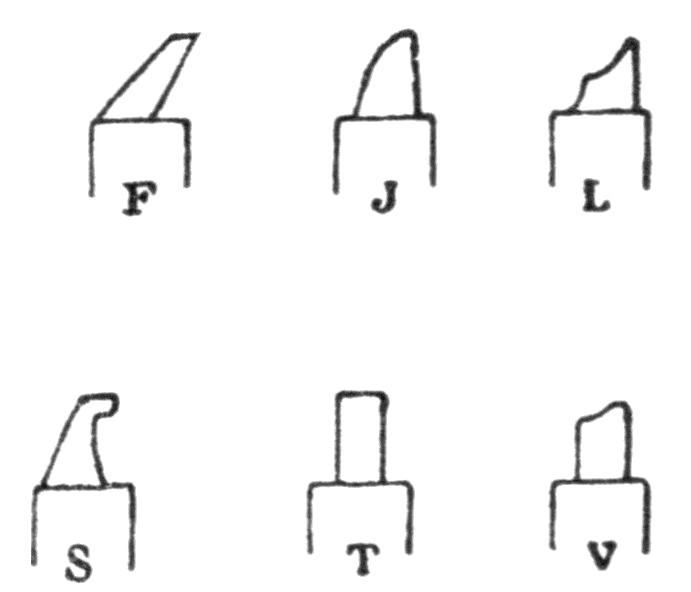
Fig. 95.
A cutter may be sharpened in the usual manner for ordinary work; but if it is desired to produce very smooth sinks, etc., one that has been carefully polished must be used for the final cut.
The blade should cut with both its edges; the straight edge will serve to form right-angled corners of sinks, while the other edge will form bevels. It is hardly necessary to add that, when a square corner formed by the first of these edges requires to be beveled by the second, the lathe must rotate in the opposite direction and the cutter be passed over to the opposite side of the center.
273. C, in the same figure, is a rounded cutter for making circular grooves. F, Fig. 95, is for cutting the groove that receives a barrel-cover. J and V are for forming the “tallow-drop” shoulders of pivot-holes, etc.
It will doubtless be observed that these cutters would form nipples that are dome-shaped and relatively somewhat high, and, for small pivot-holes, the blade would require to be narrower and of a shape that corresponds with the nipple it is desired to produce. L is for rounding off angles. S is a convenient shape for smoothing the bottom of a barrel without damage to the hook. T has a square point; it is used narrow for cutting, for example, the passage under the escape-wheel cock in a cylinder watch, and, when made wider, will serve to cut the settings for jewels. In the latter case it may either be square at the end or a little rounded at the corners.
In addition to the use indicated above, V can be employed for raising the edge of a jewel setting.
274. Sharpening slide-rest tools. A flat surface turned in the lathe will never be even unless the cutting face n in A Fig. 94, is smooth, and indeed polished, and its edge parallel to the face-plate. Some care is therefore necessary in sharpening this face. The requisite parallelism can be secured by the following method.
275. Sharpen the tool while it is held in the tool represented in Fig. 96.
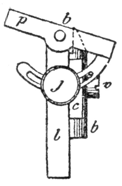
Fig. 96.
On a thick brass plate l and parallel to its plane at one extremity b, a plate p is pivoted. The inclination of p to l can be varied and it is fixed in any required position by the curved arc passing under the clamping screw j.
A small bar c is fixed to l with its edge set accurately at right angles to the line at b′ in which the two planes intersect. An examination of the figure will suffice to indicate the manner in which such a tool is used. Having set p so that it makes with l the angle to be given to the cutting face, the cutter b is held against the bar c, where it may be fixed with a screw v, or in any convenient manner, taking care to leave the portion of the cutter that is to be removed projecting beyond the face of p as shown at b′. Now pass a piece of smooth oilstone or disc of steel charged with oilstone dust over the face of p until the projecting portion is removed; if a polished face is required, this must be succeeded by a bronze or ground glass disc charged with rouge. If the plate p is of sufficient dimensions, it will not be distorted, even though only made of hammered brass; but it would of course be better made of steel, hardened if possible.
276. If the watchmaker will make a rectangular holder to fit in his tool post, with a square groove planed in its upper side that will fit some particular size of tool steel, say one-fourth or three-sixteenths of an inch, he can then buy bar steel of that size and make his cutters by simply cutting off a piece from the bar and grinding one end to the desired shapes and angles, thus saving a vast amount of time and labor in the preparation of his tools, facilitating their rapid interchange in the tool post, when working, and securing the greatest possible rigidity of the tool, as the cutting edge projects from the holder only far enough to allow the holder to clear the work.
GRAVERS AND OTHER HAND-TURNING TOOLS.
277. Hooked gravers. It is needless to do more than mention the gravers that some watchmakers are in the habit of making of worn-out files, of various forms to suit their special requirements; but we would remind learners that care is essential in fixing the position of the rest and the inclination that has to be given to the tool so as to obtain a smooth surface, and at the same time a rapid removal of metal.
The most usual forms of the hooked graver are shown in Fig. 97. A will serve to hollow out a plate, barrel, etc.; B for turning the bottom of a barrel without touching the hook; C for forming a barrel-cover groove after it has been roughed out with an ordinary graver. The bottom of a barrel can also be turned with a graver of the form D held on the T-rest at right angles to the bottom, and a slide-rest cutter can be made of this form with advantage.
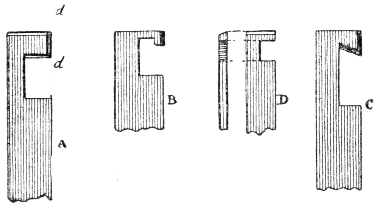
Fig. 97.
Some workmen incline the end cutting face of A slightly backwards from the perpendicular to d d, fearing lest, in sharpening, it should accidentally be made to incline in the other direction, and so make it difficult to form internal square corners.
278. Gravers for turning square shoulders, etc. Very few watchmakers are able to finish off a square shoulder by using a graver with the usual point; as a rule, when they are smoothing the surface of the pivot they allow the point to cut a ring in the shoulder, and if, instead of being sharp, the point is dull, a rough groove is the result.
To avoid such a fault it is a common practice to employ gravers with very short faces, but their inconvenience is evident. It is much better to retain the long lozenge-shaped face, but with the point modified, as indicated by B or C, Fig. 98.
The ordinary point, shown at A, can be used for cutting the back slope of a shoulder, B for forming the square-shouldered pivot, and C for beveled shoulders. The inclination of the face e d of B may vary, the angle e being more or less acute, according as more or less use is required to be made of the point. This form of graver has the double advantage that a pivot can be turned and smoothed at one operation, very little polishing being needed. Moreover, the point is less fragile, and such a graver combines the advantages of those with pointed and square ends.
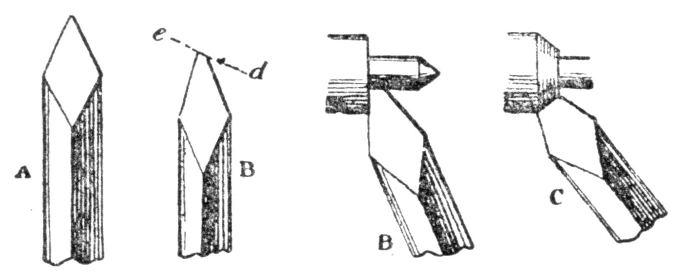
Fig. 98.
The length of this small face depends on the work required of it, thus for making a cylinder pivot it may be about a third the length of the pivot; this is found convenient for ensuring that the pivot shall be of uniform diameter. The direction to be given to the face is indicated by the dotted line e d, and a lozenge-shaped graver is preferable to one of square section for this purpose. This direction e d is very important, and frequent trials should be made so as to ensure its being always produced. The form C for beveling off a shoulder does not call for explanation.
Although of less importance than when turning with the slide-rest, the cutting angle of the graver should correspond with the nature of the metal operated on. In reference to this question see article 270.
279. Spherical turning tool. A very simple and convenient tool for forming a sphere of metal may be made by taking a hardened steel tube whose internal diameter is less than that of the sphere to be produced. This is ground square and flat at one end, and sharpened by rubbing this flat end on an oilstone. The tool is moved about over the surface of the ball, previously roughed out, and a perfect sphere will soon be obtained, the metal being removed by the internal edge of the tube. If a steel tube is not accessible it will be enough to drill a hole in the end of a softened worn-out file, subsequently hardening it.
DRILLS.
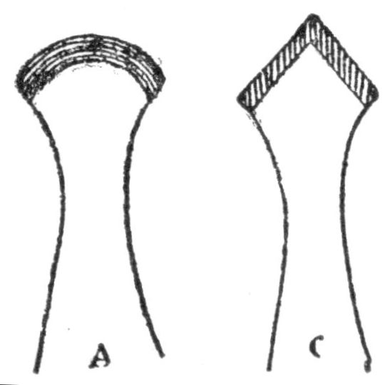
Fig. 99.
280. The forms ordinarily adopted for the blades of drills are shows at A and C, Fig. 99. The form C is best suited for perforating brass and other metals having a similar degree of hardness. The blade must not be too thick, as, if it were, there would not be a sufficient cutting edge. As the hardness of the metal operated on is greater, the thickness of the blade must proportionately increase, or what amounts to the same, the two slopes that give the cutting edges must have a less degree of inclination. If this condition of sufficient thickness be satisfied by a drill of the form C, it will perforate steel very well, but its point will rapidly wear. When operating on this metal, therefore, the form A is preferable, especially when the steel is at all hard. Such a drill with the corners rounded off and sharpened will last for a long time, if the cutting angles are not too acute. If the metal is not hard, more rapid progress may be made by adopting a blade less flattened than A, that is to say, something intermediate between A and C.
A drill may be asserted to be good if it satisfies the following conditions: the point must be in the middle of the blade; it must be made of good steel that is carefully hardened, without being heated beyond the proper temperature; lastly, it must be quite true—in other words, in rotating it must run with sufficient truth throughout its entire length, so that it withstands the end pressure required to cause it to bite, and does not bend.
281. It must not be forgotten that: (1) if a drill is driven too rapidly it will heat, and thus become softened as though too much tempered; it is with a view to prevent this that, when operating upon iron or steel, many workmen now and then dip the drill into a cold liquid (turpentine is good for this purpose), dry it, and recommence drilling, the hole being liberally supplied with oil; (2) when the blade is left too hard, the cutting edge too acute, or if a feather edge has been left by the oilstone, small hard particles that are detached from the drill will embed themselves in the hole, and this will be especially the case if it is worked too rapidly or with jerks; such particles render the operation of drilling very slow and difficult.
282. To drill steel of a blue temper. At first not much difficulty will be experienced; but when the drill reaches a certain depth and the metal seems to oppose a gradually increasing resistance, the operation must at once be stopped. If the blade of the drill be now examined with a glass, it will be easy to see which points have ceased to cut, producing instead a series of bright rings at the bottom of the hole that are very difficult to remove. Exchange the drill for one of a different form or, without reducing its width, change the form of the blade; if it was arrow-headed for example, make it a semicircle, or semi-oval, or chisel-shaped with sloping edges. All that is essential is that the form be so changed that the bright portions of the surface shall be gradually removed, and that no attempt be made to act on the whole bright surface at once. Until this hard portion is removed, the blade will require frequent sharpening.
Some authorities recommend that the hole be moistened from time to time with dilute nitric acid, which is then washed off, and renewed when a shiny surface is produced. Oil can with advantage be replaced by turpentine as a lubricant for the drill blade.
The formation of hard shining surfaces is attributed to three causes: (1) to the cutting edge being rounded, rolling as it were and hardening the surface of the metal against which it continues to move; (2) to the drill being made of bad steel or imperfectly hardened, so that small particles break off and are embedded in the metal operated upon; and (3) to a deficiency in the supply of oil, or an excessive velocity of rotation of the drill.
These difficulties may usually be avoided by observing the following precautions:
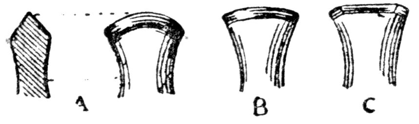
Fig. 100.
283. Blade of the drill. This should be neither as thin nor as acute as is used for drilling brass. Its angle should never be less than 100° and the incline should be at about 45°. The forms generally employed are shown in Fig. 100, at A, B and C. At first the form A is used, and, as the operation progresses, it is modified with an oilstone slip.
284. Drilling slowly with considerable pressure. If the drill rotates too rapidly or there is not sufficient oil, the surfaces of contact will be heated and shining rings will form. It is well to practice slightly, varying the speed of the wheel, in accordance with the pressure applied; the speed should be more decided when the pressure is, for the instant comparatively great. With continuous rotation, considerable pressure should be applied with moderate velocity. Constantly remove the drill to sharpen, clean the hole and have an abundant supply of oil. Whatever liquid is most effective in maintaining the drill cool will probably be the best; turpentine is better than oil, since it has the additional advantage of increasing the “bite” of the drill.
285. The part against which the drill acts should be very rigid. For example, if a hole is being made for a pivot in a cylinder plug which is not provided with a shellac backing, and is, therefore, flexible, the operation will be more tedious than when the cylinder is filled with shellac. The firmness is usually greater when the object is centered about the point to which the drill is applied.
286. Making the drill. The very best steel should be used, and the precautions indicated in article 87 should be taken in the hardening. If the steel is burnt in this process, no satisfactory results are to be expected of it. To avoid such a danger it is often advisable to leave the blade nearly round and thicker than is required, finishing with a piece of oilstone. Although somewhat more tedious, this method has the advantage of ensuring that, after hardening, all the metal that is most liable to have been burnt is removed.
The drill must be short, the blade being thick and not much reduced at the shoulder, in order to stand pressure when in use. A drill that has been several times hardened is rarely good.
287. Finished drills. We would here draw the attention of watchmakers to some beautifully made drills that have been introduced and are known in the trade as “finished” drills, in contra-distinction to the well known pivot drills that are always sold in the rough. They are of two forms, corresponding to A and C, Fig. 99, for steel and brass respectively; they are made of the best steel, carefully hardened and tempered to the requisite degree; and a principal recommendation consists in the fact that, while being moderate in price, they are of definite graduated sizes, extending from 0.1 mm. to 2.5 mm. (0.004 to 0.1 inch), a range which comprises 37 distinct sizes.
288. Semi-cylindrical drills. These drills give excellent results when driven by a wheel, and, although they have been long in use by engineers, they are hardly known to watchmakers.
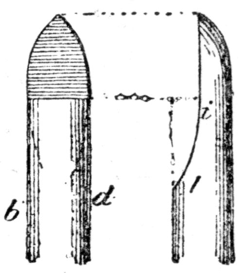
Fig. 101.
The simplest form is a cylindrical rod rounded at its end and then filed down to a trifle less than half its thickness, as seen at b d and l i, Fig. 101.
The length of the point is greater or less according to the nature of the metal to be operated upon, but under no circumstances must the point itself be sharp. With the form shown at b d, some of the rod that is left cylindrical must be partially filed away; a better shape is indicated by the dotted lines, all the metal being removed that is outside the line i l. With such a drill the hole is smoothed immediately after it is made by one or the other cutting edge of the portion i l. It should be sharpened on the round, not on the flat surface (or at any rate very slightly), because the thickness would be rapidly reduced and the blade made smaller. When such a drill does not turn true the back of the blade can be reduced, starting from the cutting edge, it being observed that, with the continuous motion of the wheel, only one edge acts. After a few trials it will be found easy to use this form of drill.
It possesses this very great advantage: when fixed in a drill-chuck, it can be turned exactly round, of the required diameter and finished; so that, whenever replaced in the chuck, one can be certain beforehand that the hole drilled will be of a definite diameter.
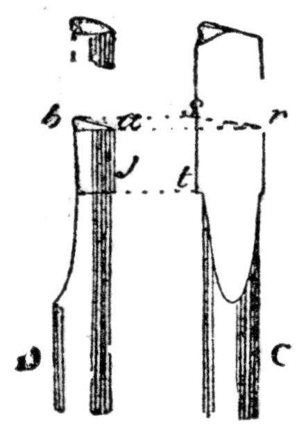
Fig. 102.
289. Fig. 102, shows, at C and D, another form of semi-cylindrical drill; the first, C, is a front and the second a side view. The angle a is formed by a sloping semicircle and the stem of the drill is of less diameter than the head, as indicated by the shoulder j. The angle t s r and the one between the face D and the plane b a must not be too acute.
This drill works evenly, but two conditions must be satisfied; it must be maintained perfectly true by the chuck, and, in commencing, both sides of the blade must engage against the sides of a conical opening that forms the beginning of a hole which has to be enlarged.
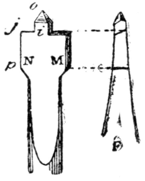
Fig. 103.
290. At F and N M, Fig. 103, are seen front and side views of another form of drill. While acting in a similar manner to the others described above, it differs from them in that the blade also cuts with its two sides; the edges, p, i, i, o, are sloped off backwards to form cutting angles. The shape is indicated to the right of M, this portion being the exact inverse of the side N.
As with the drills previously considered, a few trials must be made to decide upon the best slopes for the cutting angles, etc., according to the metal operated upon. They may be retained as left by the lathe, or very slightly inclined, on the faces p and i. All these forms of drills require to be mounted so as to run very true. The point o must be accurately central. A hole that has been already drilled small can be rapidly enlarged by such a drill as this last, the pin o, having the same diameter as the one originally drilled.
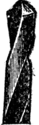
Fig. 104.
291. The Twist Drill. The Morse twist drill, shown in Fig. 104, is rapidly coming into favor with watchmakers for the heavier classes of work, and is very desirable when drilling deeply, as this form of drill heats slowly and the particles are carried to the surface of the work. A large range of sizes in these drills are now carried in stock by the material dealers.
LATHE ATTACHMENTS.
292. Tailstocks. Besides the regular tailstock which accompanies the American lathe there are several other varieties made for use on special kinds of work. Fig. 105 illustrates the half open tailstock which is cut away so that the spindles can be laid in, instead of being passed through the holes. The fixture will be found exceedingly convenient when several spindles are to be used for drilling, counterboring and chamfering. Fig. 106 illustrates the screw tailstock, an attachment which is very convenient for all kinds of heavy drilling, the spindle being moved by a screw with hand-wheel attached. Fig. 107 illustrates the traverse spindle tailstock, which will be found very convenient for straight drilling and especially where the watchmaker has considerable drilling to do.
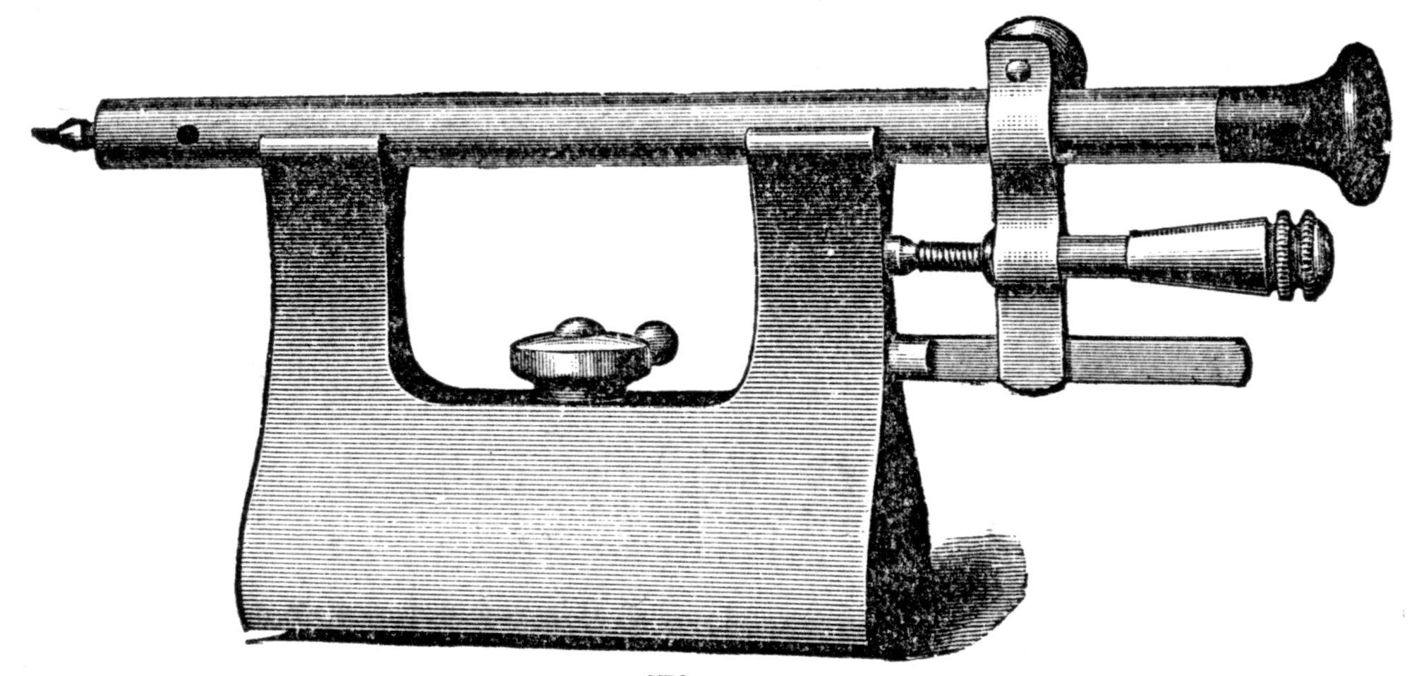
Fig. 105.
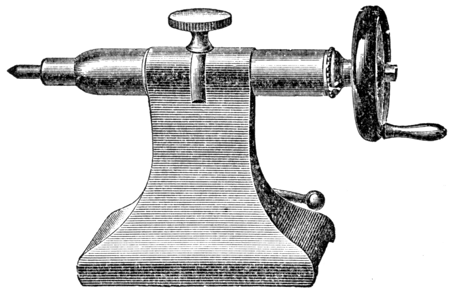
Fig. 106.
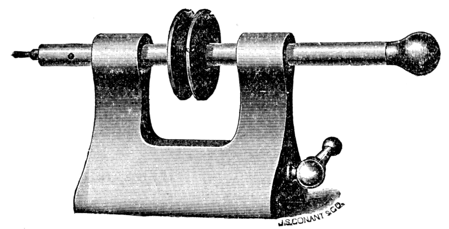
Fig. 107.
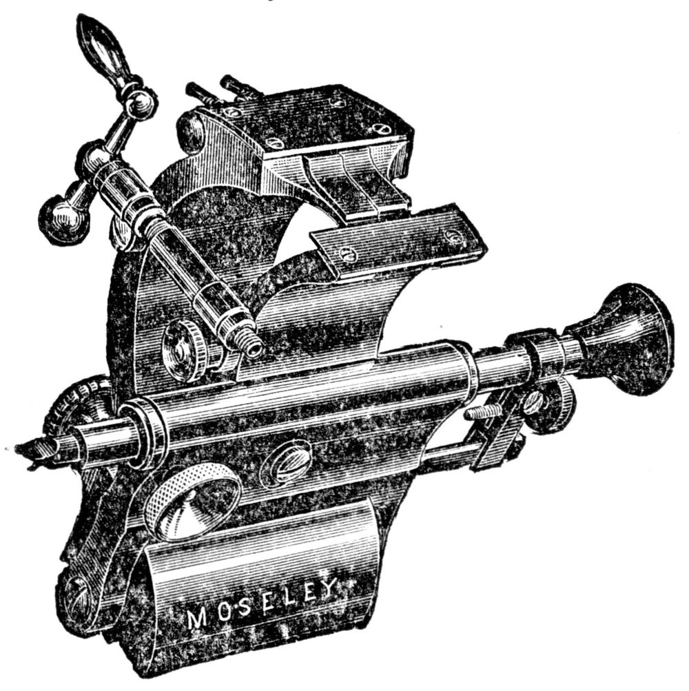
Fig. 108.
293. Jeweling Caliper Rest. Although this tool was invented and manufactured for the purpose of cutting jewel settings it may be used to great advantage in countersinking for screw heads, opening wheels for pinions or bushings, etc. The sliding jaws of the calipers should be so adjusted that when the swinging part is brought back snugly against them, the front cutting edge of the cutter in the sliding spindle will exactly line with the center of the lathe spindle. Then if the calipers are at the right height, when a jewel or jewel setting is placed in the jaws of the caliper it will move the edge of the cutter outward from the lathe center just half the diameter of the jewel then in the caliper and the cutting made at that distance from the center will exactly coincide with the size of the jewel to be set. If however, when set and worked as above, it is found that the hole cut is too large for the jewel, it will indicate that the calipers are too low down and should be raised, provision for which is made in the construction of the tool. Upon the other hand, if the cutting is found too small to fit, it will indicate the calipers should be lowered. The final cutting for the jewel seat should be made by running the center straight inward from the face of the plate; the adjustable stop screw on the back end of the sliding spindle, serving to gauge the depth of the cutting.
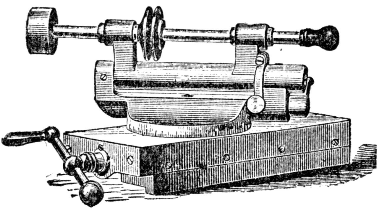
Fig. 109.
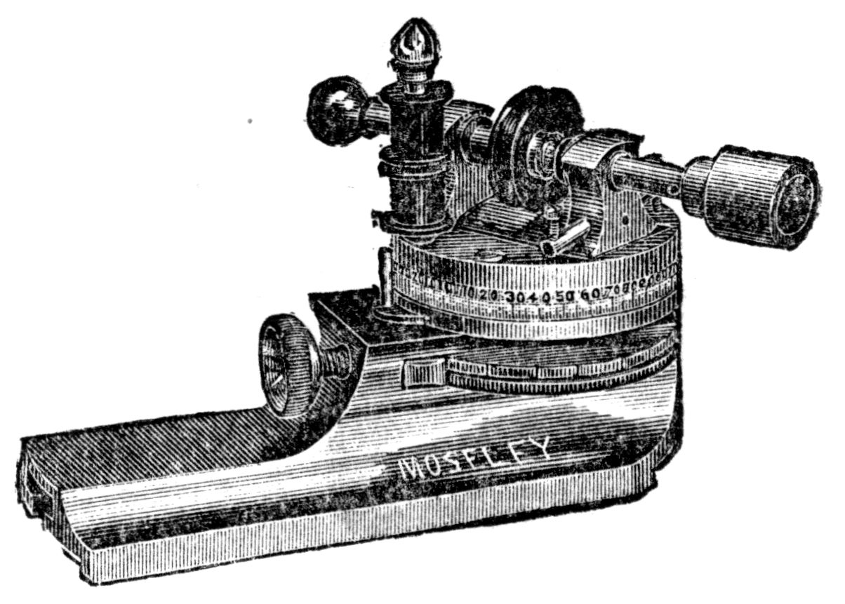
Fig. 110.
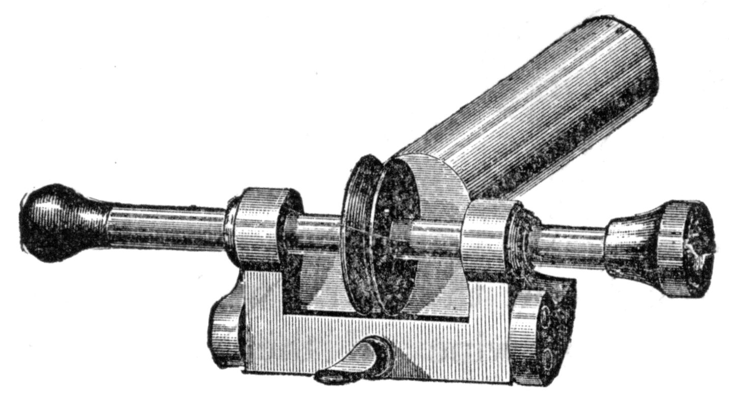
Fig. 111.
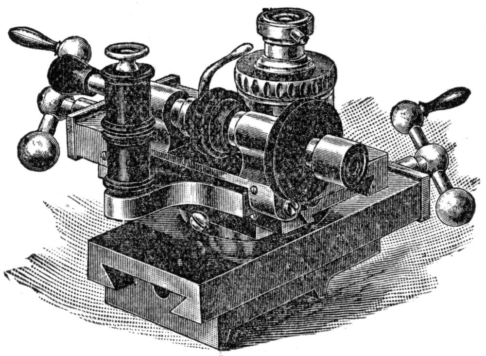
Fig. 112.
294. Pivot Polishers. The pivot polisher is used for grinding and polishing conical and straight pivots and shoulders. It is also used for drilling, polishing or snailing steel wheels, milling out odd places in plate or bridge, where only a part of a circle is to be removed, etc. In the style shown in Fig. 109, the American Watch Tool Co.’s polisher, and Fig. 110, the Moseley pattern, the circular base is graduated to degrees and the fixture can be set at any angle. The spindle has a taper hole for drill chucks, which makes the fixture very useful for drilling either in the center or eccentric and by using the graduations on the pulley of the headstock an accurately spaced circle of holes may be drilled. Fig. 111 illustrates the polisher made by the Faneuil Watch Tool Company, and is intended to be mounted on the slide rest. Fig. 112 illustrates the Johanson pivot polisher and in general principle is like the others. This style is made both for use on the slide rest and also for the hand rest. When used in the latter, a stud, shown in Fig. 113, is screwed into the base plate and supports the tool in the hand rest, so as to be readily adjustable in any direction. When used in the slide rest, this stud is removed and the plate clamped between two hollow cylindrical supports by a stud which is slipped into the groove of the slide rest and fasted by a nut at the top, the whole forming a turret-like mount of great strength and upon which the machine can be readily swiveled in any direction. In general, polishers are used as follows: After the pivot is turned to proper shape, put on your polisher, with the lap back of the pivot, usually the cast iron lap first. A square-cornered lap for square shoulders and a round-cornered lap for conical pivots. The laps for conical pivots can be readily cornered with a fine file, and cross-ground with fine oilstone to remove any lines made by graver or files. Lines on the end can be removed the same way, or by means of the fingers often rubbing them on a piece of ground glass which has on it a paste of oilstone powder and oil, well mixed. Oilstone powder and oil used on the lap, or No. 1 crocus will rough out the work well. When roughed out to your liking, wipe off the oilstone powder or crocus and with a little oil touch the pivot gently; repeat the second time. Then change lap for one of boxwood or brass and use crocus No. 4, very fine, and ground down to a paste. Proceed as with the first lap, being careful at all times to keep the lap properly oiled and not pressed too hard against the work, particularly in the last operation. Be sparing of your grinding and polishing material as a little will accomplish as much work as a large quantity and do it better. Bring the lap up carefully against the work until spread all the way around, then proceed, bearing in mind that grinding is not polishing, and that to polish nicely the work and lap must be very nearly the same shape. Fig. 114 illustrates the Hardinge pivot polisher, which is a hand polisher and much more simple in construction and use than those mentioned above. It is attached to the lathe bed the same as the T or hand rest. Polishing and grinding slips are furnished with this attachment, as with the others.