PART II EVERYDAY MACHINES
Reading edition
I SOME PRACTICAL ADVICE
Some of our inventions and some of our discoveries are of comparatively recent date, but most of them had their beginnings centuries before historical times, as many of our greatest inventions are the result of gradual growth and development. The early discovery, by some unknown persons or persons, of the making of bronze and the hardening of it, led up to stone and woodcutting, perhaps to the breaking-up and smelting of iron ore, and the extraction of the metals. This again opened the way for the making of steel, a discovery that placed in the hands of man a source of power which enabled him to overcome many natural difficulties. One improvement led the way to another, and made other improvements possible. Take locomotives and steamboats for instance. The making of a raft, no doubt, suggested the canoe, and this led to the built-up boat, and the ship. The paddle and the oar doubtless led up to the sidewheeler, and the scull to the propeller. The crude steam engine of Hero very likely suggested the steam engines now in use, and this new power rendered it easy for Stephenson and Fulton to perform their work; but, if either of these inventors were to come back to the earth and examine the great steamers of to-day, or the perfect and powerful locomotives now in use, they would be surprised to think that the present tractable monsters, were the outgrowth of their early efforts.
In the same manner may be traced the same gradual growth in all the arts and sciences; for step by step, in every department of life, have completeness and perfection come to us. It is not yet one hundred years since Congreve invented or rather completed the invention of the "Parlor match," called in his day, the "Lucifer match." This grand achievement was accomplished after many failures in the efforts of chemists for ages. The perfection of the match was a great blessing to humanity, as the old methods of making a light or fire were tiresome and very uncertain. So it is with many of the blessings we enjoy to-day: they are simply the results of the struggles of many unknown minds, the threads of which were gathered up and pieced together by one master mind, so as to be made useful and profitable to mankind.
In the early and middle ages, the inventor was looked upon as a wizard, a sort of inferior demon, or, at best, an uncanny kind of man, and a proper subject for the stake. When, by superior wisdom and skill, he invented some machine or device, or discovered some new and better method of accomplishing a useful end, he was at once looked upon as a necromancer in league with his Satanic majesty, and, therefore, unfit to associate with or be recognized as a Christian. History records many instances of inventors and progressive men being persecuted—and executed—because of their having discovered or invented something which would interfere with some vested or imaginary rights. The new inventions must be destroyed or put away out of sight and hearing, and the most powerful influences were employed to bring about this result. The stories told of Friar Bacon, Papin, Crompton, and hundreds of other inventors, give us a few of the reasons why so little progress was made in the arts and sciences previous to the sixteenth century.
Down to a period within the past few years the term invention has been considered almost synonymous with the word chance. An inventor, was a lucky individual, who had happened to hit upon some new idea, not so much by his own great ability as by good fortune, similar to that which brings success to the purchaser of a lottery ticket.
In many cases this was really the true state of affairs. Men who experimented in various mechanical pursuits often stumbled upon results, which they perceived to be useful and valuable, and, if they protected the invention by patent, they often became wealthy.
At the present time this meaning of the word invention must be greatly modified, if not altogether abandoned. The law which controls the action of the forces of nature is becoming so well understood among all classes of mechanics that chance invention, in the early sense of the term, has almost become an impossibility. Success can be assured only to the man who has tried to win it by the acquirement of the necessary knowledge, to be obtained by steady application and hard study. In the pursuit of discovery, the old saying, "knowledge is power," never has had more force than when applied to unravelling the tangled web of nature's mysteries. "Science," says Lord Brougham, "is knowledge reduced to a system."
A man may have a lifetime of practical experience and amass a fund of knowledge of great use to himself, but entirely unavailable for others. But if his experience be combined with that of other men and systematized into a regular order, it becomes part of the science of that branch of industry, and although the person himself may have a profound contempt for science and theory his work may be quite scientific.
Ignorance, in the past centuries, was another great factor in preventing mechanical progress. New machines and labour-saving devices were looked upon by the great mass of workers as contrivances designed to deprive them of the means of making an honest livelihood, and this point of view caused the people to smash and burn many machines that had cost great labour and expense to the unfortunate inventor. But, as public schools became more numerous and learning increased, the way of the inventor became smoother. The more enlightened nations encouraged inventors and inventions, and now our country has on its statute books laws for this purpose, the most liberal in the world.
The opportunities for obtaining mechanical and scientific knowledge and technical instruction are now so many and so easy of access that inventors have but little trouble in acquiring the data and facts essential to their purposes. The earliest students had nothing but their own observations and experiences to build on, and even as late as the eighteenth century, men had to grope in the dark for the data required to carry out their ideas. A brief examination of the early treatises on mechanics and the rude illustrations in the works of Leopold, Amoutons, and Desaguliers will reveal the germs of many modern machines.
The inventor of to-day, however, must proceed by a different path from his predecessor, if he expects to succeed in the present advanced state of mechanical arts. The demonstration of the mechanical equivalent of heat, the discovery of the correlation of the physical forces, and the development of the sciences of thermo-dynamics have furnished powerful weapons for the advancement of mechanical science, and he who does not use them is at a woeful disadvantage in the fight. There is no "royal road" to success for the inventor, and I hope you will always bear this in mind when attending to your studies, for you must remember that it is nearly always necessary to use formulæ and symbols to express relations, which are hardly within the range of words, and often a combination of data obtained from different sources may be used to derive entirely new relations.
It is here that invention, in the modern sense of the term, comes in to hold a place midway between theory and practice, and may be properly called a science.
THE LAWS OF GRAVITATION
Suppose a one-pound weight is suspended by a string: there is a tensile stress in the string, varying slightly at different parts of the earth, but always the same at the same place, say, Newark, for the variation is very slight within a pretty wide area. If we take a spring balance and graduate it in pounds at Newark, such a balance will accurately indicate forces in pounds wherever it may be used. The stress produced in a string carrying a one-pound weight at Newark is the unit of force. If the string with its weight is hung from a nail, the nail is pressed on its upper side with a force of one pound. The same pressure may be produced by pushing the nail downwards from above, using a short piece of stick; in such circumstances, the stick bears a compression stress of one pound. This is a good, common-sense definition of force, though it does not by any means cover the whole subject. The word force is used in a different sense by persons who speak of the force of gravity. When a one-pound weight is suspended by a string, as stated in the foregoing, the attraction between the mass of the weight and the mass of the earth is balanced by the stress in the string. We can double the stress by doubling the weight, and in this way, by adding weights, we can make the force of gravity very great. But the force of gravity is spoken of as an invariable thing, and it is said to be equal to 32 (roughly). If any weight whatever be allowed to fall freely (for reasonable heights and neglecting the effect of the resistance of the air) it will be found that at the end of the first second it will have a velocity of 32 feet per second; at the end of the second second it will have a velocity of 64 feet per second; and generally at the end of any number of seconds its velocity will be 32, and the rate of increase of velocity (acceleration) is 32 feet per second, all of which has been previously explained. It is found convenient to call this acceleration gravity—it is inaccurately called the force of gravity, it varies at different places on the earth. It is usual to designate the acceleration by the letter g, and we speak of the g, or gravity, of the place. This seems to cover the point of inquiry completely.
The subject of specific gravity is a far-reaching one, and includes the testing of liquors for revenue purposes and many other things of a scientific nature; but when we speak of specific gravity in an ordinary way we mean the comparative weight, bulk for bulk, of water at a certain temperature. The specific gravity of a substance like coal can be ascertained experimentally. By means of a specially adapted and delicate balance, the sample of coal is first weighed in the ordinary way, after which it must be weighed suspended in a vessel of water. Weighed in water, it will be found the coal does not weigh so much. If the loss of weight, or the difference between the first and second weighings be taken, and the first weighing divided by this loss of weight, we obtain the specific gravity of coal. For example, suppose a sample of coal weighs in the ordinary way 20 ounces, and in the water only four ounces, showing a loss of weight of 16 ounces. Divide 20 by 16, and we get the specific gravity of the sample of coal, viz., 1.25.
The use of specific gravity is of great importance in mining, with regard to analysis of the minerals worked, for with a class of coal having the same relative composition, qualities, and calorific power per ton of coal employed for different purposes, yet having a higher specific gravity, the room required for storage or transport will be less. This is an important factor, where there is limited space, as in depots and naval vessels. It is also employed in the arts and industries for many purposes, and is particularly useful to workers in precious metals, as the amount of alloy or baser metal may be determined by it that have been used in the manufacture of jewellery, plate, and similar articles.
To put it briefly: Specific gravity is the ratio of the heaviness of any substance to that of water. The specific gravity of water is taken as unity, and that of any other substance is expressed as a decimal. Tables of the weight and specific gravity of substances can be found in any good hand-book of engineering.
HOW TO ADJUST SEWING MACHINES.
Sewing machines often get out of order, and it is not always that an expert is at hand to adjust them, so a few general observations on the subject of these household machines may prove useful and interesting to every one who is at all mechanically inclined.
There are several distinct types of machines, but we shall confine our remarks to the Singer vibrating shuttle, the hook shuttle types, and one or two others. To secure a perfect stitch in the vibrating shuttle machine, and to keep it from puckering thin goods, such as Japanese silks, muslins, and voiles, though possible, is difficult. Success depends entirely on the careful fitting of parts and the skilful adjustment of the machine to the particular fabric. In the first place, it is essential that a machine should work quite freely, a point not of such great importance if it is used for rougher classes of work.
Machines used for domestic purposes, like the V. S. (vibrating shuttle), often stand unused for weeks together, so that the oil thickens and makes a machine run somewhat heavily and unevenly. This may indirectly affect the regularity of the tension, especially with thin goods. Therefore, it is important to keep a machine clean and regularly oiled. Important parts are often overlooked during the operation; in fact, many users of machines do not know how nor where to oil one properly. Therefore Figs. 79 and 80 will be helpful, as they show the location of oil holes and parts to be oiled, and the illustrations will serve as a guide to other machines. In these figures, it will be seen that there are a number of parts to oil which could very easily be overlooked. When a machine has been unworked for a length of time, the application of a little paraffin will cleanse the parts which should afterwards be oiled thoroughly with a good quality of machine oil. The shuttle raceway, where the shuttle works, should be wiped out with an oily rag. Any lint or dirt which has accumulated inside the shuttle at the nose end should be withdrawn, as such might retard the unwinding of the bobbin. It is imperative that the cotton should pull evenly, that is, free from jerks; this refers to the upper as well as to the lower tension.
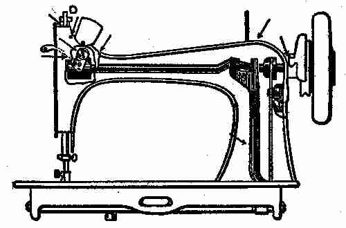
Fig. 79. Section showing oil holes
For silk and similar materials, best results can be obtained if fine cottons are used. Numbers 60, 70, or 80 would be preferable to No. 40. A good quality of fine silk is even better. It must be remembered that when working on thin silk, say two thicknesses, a coarse cotton cannot be locked centrally. Fine cotton will need a fine needle, which necessitates a fine hole needle plate.
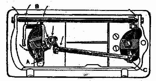
Fig. 80. Action of shuttle in the race
If, after the foregoing points have been attended to, the machine runs easily, the parts fit properly, there is no end play to the upper shaft and the cottons pull evenly, yet the tensions are erratic, attention should be given to the loop as it draws off the shuttle heel. In machines of the C. B., O. S., and especially the V. S. class, there is a tendency for the loop to hang on the heel of the carrier, or to become trapped between the shuttle and the carrier heel. In the two former types of machines, the heel of the carrier should be rounded so as to induce the cotton to pass off as freely as possible. Sometimes it is necessary to time the shuttle a little later, that is, put the carrier back a little to allow the loop to draw off more in a line with the hole in the needle plate.
In V. S. machines the carrier is already rounded off at the heel. By referring to Fig. 80, the action of the shuttle in the raceway can be seen, which is from A to B. The shuttle, having just entered the loop, is about to move to B. This movement can be regulated by an eccentric screw and nut (Fig. 80). When a machine has been taken to pieces and cleaned, this screw is not always replaced to the best advantage. If the shuttle moves too much toward B, the loop is carried by the heel of the carrier, and, at the same time, the shuttle cotton, by bearing tightly on the needle plate, pulls the shuttle toward the carrier heel, thus making it difficult for the loop to release itself. More tension is applied, perhaps more pressure is put on the take-up spring, yet the uneven tension is not overcome, and owing to the softness of the fabric, it is drawn up or puckered. The remedy is to turn the screw C (Fig. 80), until the carrier is in a position to allow the loop a free exit.
For such soft materials as mentioned it may be necessary to slacken both tensions. It should be remembered that the upper tension is generally somewhat tighter than the under one, and this should be a guide to the adjustment of the latter, according to the fabrics to be stitched.
To prevent puckering when the tensions are correct, reduce the pressure of the foot by loosening the thumbscrew D (Fig. 79). Use a small size stitch—set the feed so that the teeth are just above the needle plate. Do not have the teeth too sharp, and if necessary, rub off the knife edge with F emery-cloth. Make the foot to bear squarely on the needle plate, and the feed square to the presser foot. Round off all sharp edges from the under side of the foot, especially the back edge. Special feeders are made for silk goods in machines used for factory work, which overcome the difficulty of puckering.
By attention to the foregoing instructions, a machine should work easily, especially if the fabric is slightly pulled from behind the pressure foot.
In C. B. machines, attention should also be given to the loop as it passes over the bobbin case and off the stop pin, it being necessary sometimes to round off the latter. If the tension spring screw projects too high or is rough, it may occasionally catch the cotton.
The machine shown at Fig. 81 is of the "Rotary Hook"—zigzag type. Its uses are similar to that of the oscillating shuttle type, but its construction is rather more complicated.
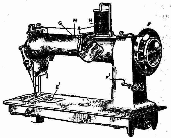
Fig. 81. Rotary hook—Zigzag type
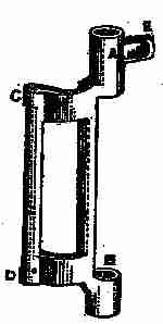
Fig. 82. Rocking frame
The machine may be said to consist chiefly of an upper and a lower shaft, each having two cranks. In the vertical portion of the arm are two links which connect the shafts, causing them to work in unison with each other. The upper shaft gives motion by means of a cam and link to the needle bar and take-up lever; while the lower shaft, by means of three gear wheels, gives the rotary movement to the hook or shuttle, and by an eccentric cam and segment lever the necessary motion is given to the feed or stitch mechanism. Figure 82 shows the rocking frame into which the needle bar is fitted at A and B, while, at C and D, it is recessed to receive the taper ends of two screws, which pass through the face plate end of the machine arm. These screws are held secure by lock nuts, so screwed in as to allow the frame to rock freely. A ball-headed screw is fitted at E, to which is fastened a connection rod extending to a switch lever situated about the centre of the arm. This lever, by means of a cam movement, gives the vibrating motion to the needle bar, which can be regulated according to the relative position of the connection rod and lever. When the rod is at the bottom of the lever, a wide throw is obtained. By raising the rod a narrower throw is given, and if raised to the position shown in Fig. 81 no vibration will be given to the needle bar. The needle bar can be raised or lowered by loosening the screw that secures it to its link collar, which will be better seen by removing the face plate. Most needle bars have two marks upon them, and they should be set as follows: Remove the face plate, and turn the hand wheel F (Fig. 81) toward you until the needle bar link has reached its lowest point of travel.
Loosen the set screw of the needle bar collar, and set the needle bar so that its highest mark will be just level with the bottom of the rocking frame (Fig. 82). Then tighten the set screw, give the hand wheel a spin round, and again examine the position of the mark when the needle bar has reached its lowest point of travel, to make sure that no mistake has been made. Of course, it is necessary when parts are badly worn to set the needle bar a trifle lower, but this can be done after the foregoing rule has been adopted and proved a failure. In case of any unnecessary looseness in the middle bar or any of its connecting parts, they should be taken out and new parts fitted. The position of the needle may be altered to the right or left by loosening the screws G and H (Fig. 81), and adjusting the connection rod. Care should be taken not to set the connection rod too low down, or the needle may strike on the needle plate and cause trouble.
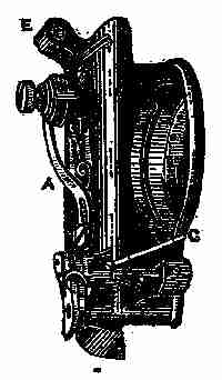
Fig. 83. Section showing face plate removed from machine
Fig. 83 shows the face plate removed from the machine arm, A being a tension release lever. When the presser foot is lifted to its highest position, the end of the lever goes between the tension disc, thus releasing all tension, so that materials can be taken from the machine without drawing slack cotton, or putting any unnecessary strain on the needle. When the presser foot is lowered, this lever should withdraw itself from the disc, thus allowing the proper tension to be put on the cotton. In some machines the withdrawal of this lever depends on a stud screw, fastened to the needle bar and projecting through the face plate. In the downward course of the needle bar this stud screw touches a spring, and causes the lever to trip backward. Should the spring become strained, or the stud screw become raised up a little, the release lever may remain between the disc and cause trouble. Sometimes it is necessary to bend the lever forward or backward to ensure its proper action.
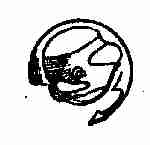
Fig. 84. Hook ring
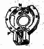
Fig. 85. Hook guide
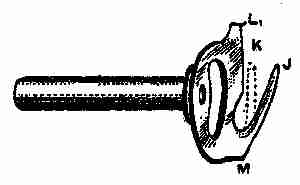
Fig. 86. Hook driver
The hook or shuttle is rotary in motion. The hook (Fig. 84), is fitted to a ring, which is fixed to the hook guide (Fig. 85) by means of three small pins, and it is prevented from falling out by a steel cap secured with two screws and springs. The hook is carried round by a driver (Fig. 86). Much depends on the hook, driver, and hook guide, so that a little detailed information is necessary. The hook driver must be a perfect fit in its bearings and free from sharp places where it comes in contact with the hook. The body of this driver is generally hardened, but the prong J (Fig. 86) is left soft so that it can be bent to meet requirements. When a machine is stitching, the hook driver rotates, and the prong J draws a given amount of slack cotton from the bobbin case. The farther this prong stands out, the more slack cotton it draws off the bobbin. The prong may be bent inward, as shown by the dotted lines, but care must be taken not to drive it in so far as to allow the needle when descending, to strike on it, or to deviate from its true vertical position. Points K and L fit between the nose and neck of the hook, while M comes against the heel. The hook is driven alternately by points K and M. When the hook is just entering the loop formed by the needle, it (the hook) is being driven by the driver wheel or M, and an opening is being made between point K and the hook nose for the free passage of the cotton. When the loop is being drawn off the hook by the take-up lever, the hook is driven by point K, and an opening is made between M and the heel of the hook for the exit of the cotton. There must always be sufficient clearance at points K, L, and M for the cotton or thread being used. As the heel of the driver M wears, the space at K will be reduced. Sometimes this can be remedied by bending the driver in at M, by giving it a blow with a hammer, placing a brass punch at M, but this should not be attempted if the driver is very hard. There is a means of adjustment provided in the hook guide (Fig. 85). This part is held in position by two set screws N and O. At the left of O is a small adjusting screw P. Supposing there is not sufficient space at point K (Fig. 86), for the cotton to pass, loosen the screw O (Fig. 85), and slightly tighten the screw P. This will tilt the hook guide and give more space. Should the screw P be turned in too far, the point L (Fig. 86), will be brought in contact with the narrow part of the hook near the neck, and this will impede its freedom, so that if allowed to run at much speed, the probable result will be the breaking of the hook off at the neck. This should be noticed in fitting a new hook, as the adjusting screw P (Fig. 85) will in all probability require loosening. The screws at N and O, however, must be kept quite tight. At each side of N is a small screw hole. The screws which fit here are for adjusting the hook closer to or farther from the needle. As an example, supposing a very fine needle has been used in the machine, and it is now required to take a very coarse one on account of the thick material to be stitched, the hook in all probability would strike the needle, indicating that the hook guide requires moving back a little. To do this, loosen the two small adjusting screws and tighten the set screw in N. Afterward try the set screw in O to ascertain if it is secure. In this way, the hook is thrown farther from the needle. Loosening the screw at N, and tightening the adjusting screws, will bring the hook forward. If the hook stands too far from the needle, it is likely to miss the loop. The hook nose must be well pointed and perfectly smooth, roughness or sharpness removed from any part of the hook over which the cotton passes during the formation of a stitch.
Hook rings are made in three sizes, numbers 1, 2, and 3. Number 1 is for a new hook, numbers 2 and 3 are for fitting as the hook wears. No matter what size of ring is used the hook must have perfect freedom. Sometimes the three pins in the guide draw the ring, and cause the hook to bind. It is best, therefore, to fix the ring to the guide, and then test the hook. If it is at all tight, grind it on the rim by means of an emery wheel or a grindstone. If neither is available, use number 1 or number 11⁄2 emery cloth first, finishing with number 00 emery cloth. It is better to have the hook a little loose, even sluggish, than too tight. The timing of the hook will be dealt with later on.
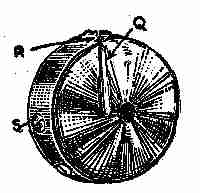
Fig. 87. Bobbin case
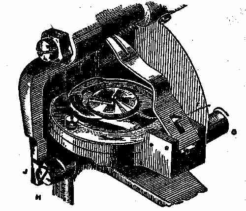
Fig. 88. Bobbin case in position
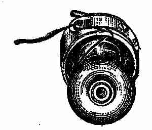
Fig. 89. Bobbin in position in bobbin case—Method of threading
The bobbin case (Fig. 87), fixes to a stud in the centre of the hook. It is held in position, that is, kept from revolving with the hook, by means of a stop pin, Q, fitting between a holder. The tension is obtained by a spring, R, which is regulated by turning a small screw, S, to the right to tighten and to the left to loosen. Fig. 88 shows the bobbin case in position, with the holder raised ready for taking it out of the machine. Fig. 89 shows the bobbin in position in the bobbin case and method of threading, and Fig. 91, the direction the cotton should draw off the bobbin when it is in the machine. It will be noticed that the cotton pulls in the opposite direction to which the hook travels, as shown by an arrow in Fig. 88. The bobbin case holder (Fig. 91), should prevent the bobbin case from revolving with the hook. As parts wear, the bobbin case is liable to slip past the holder, causing the cotton to be stranded and broken. When such is the case the holder should be bent as shown by (Fig. 92), but it must not fit so tightly against the bobbin case as to cause the cotton to become trapped. The holder is held rigid by means of a catch and spring T (Fig. 88). Should the catch or holder become worn, fit new parts by driving out the pins U and V. Any sharpness or roughness on the forked part of the holder should be removed. Should the stop pin Q (Fig. 87) become loose, it should be soldered and well cleaned with an emery cloth. The centre tube of the bobbin case should also be kept quite firm. Should it become loose, place it over some hard substance, rivet it until tight, and thoroughly smooth with very fine emery cloth.
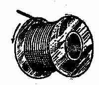
Fig. 90. Direction cotton should draw off
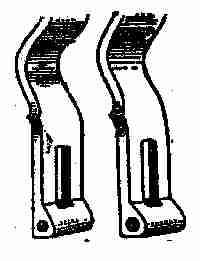
Figs. 91 and 92. Bobbin case holders
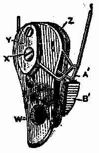
Fig. 93. Take-up spring
The take-up spring (Fig. 93) is attached to the face plate, and is shown in position in Fig. 83. Replace a new one as follows: First take out the set screw W (Fig. 93), and remove the complete thread controller from the face plate. Then take out the screw and withdraw the old spring. Place the ring part of the new spring in the recess between plate Y and back plate Z, and replace the screw X, being careful not to get the spring fastened under the screw head. This done, fix the spring and other parts on the face plate. A small barrel with a slot in it receives the coiled portion of the spring. See that the part of the spring that is turned in enters the slot in the barrel, then replace the screw W, but before tightening this screw, see that the hooked part of the spring A´ rests on the regulator B´, which determines the amount of action given to the take-up spring. By raising it, less action is given. The amount of pressure on the spring is regulated by adjusting the barrel in the face plate. Take off the face plate, loosen the screw C (Fig. 83), fix a screw-driver in the rear of the barrel (seen inside the face plate), turn it toward you for more pressure, and backward for less and tighten the set screw C.
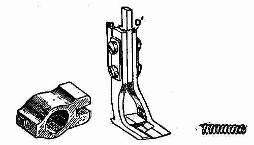
Figs. 94, 95, 96. Presser foot with details
Presser feet are made solid for ordinary purposes, although alternating feet can be fitted when desired. Figs. 94, 95, and 96 show a pressure foot, collar, and spring. To fix this foot, remove the ordinary presser foot, turn the foot bar round by loosening the set screw, so that the groove made for the reception of the presser foot is directly behind the needle. Put on the collar (Fig. 95), then turn the foot (Fig. 94), and screw it in position. Next place the spring each side at the points D´ (Fig. 94), press down the collar (Fig. 95), and secure it by its set screw. The springs will act on each half of the foot, and keep them firm, though the material be uneven. The foot is particularly useful when overseaming a hem or the top band of a lady's boot, etc. To time the hook and needle, raise the connection rod so as to produce no throw, and tighten the screw as in Fig. 81. Then take off the needle plate and remove the slide E´ (Fig. 81) under which will be seen a crank and screws.
Now turn the machine back as at Fig. 88, lift up the bobbin case holder by pressing the catch T, and remove the bobbin case. Take off the hook guide cap by removing the two screws. Turn the hand wheel F (Fig. 81), toward you, until the needle bar has descended to its lowest point of travel, and loosen the crank screw farthest from you. Having done this, continue turning the hand wheel until the needle bar has risen. With the lowest mark level with the rocking frame casting, at this point, examine the hook, the point of which should be just up to the needle. If otherwise, loosen the other screw in the crank under the plate E´ (Fig. 81). Be sure the needle bar mark is level with the rocking frame, place the hook with its point just up to the needle, and tighten the crank set screw, being careful to have no end play to the short shaft. Again examine the needle bar and hook and if in proper time finally secure crank set screws and replace the fittings previously removed. Thread the machine as indicated (Fig. 81). Set the needle as high in the bar as it will go, with the long groove facing the operator, and thread the needle from the long groove side. The stitch regulator will be found at F´ (Fig. 81). The raising of it will shorten and the lowering of it will lengthen the stitch. The feed should be set about one thirty-second of an inch above the needle plate when at its highest point. To raise the feed, turn the machine back as in Fig. 88. Near to the part G (Fig. 88) will be found a large set screw. Loosen it and press the lever H (Fig. 88) upward raising the feed bar J as high as required, and tighten the set screw at G firmly. To remove the feed for cleaning and sharpening, take off the needle plate, under which will be seen two feed set screws. By unscrewing these, the feed can be lifted out.
One of the modern machines on the market is the Wheeler and Wilson, known as the Number 61, which is of rotary hook principle. The hook forms part of the under shaft, somewhat similar to that known as the D9 W and W. This hook and shaft revolves in two long bearings, and is held in position by a fluted wheel, which forms a collar at the right-hand end; thus when set properly no end play is permitted. This is an advantage over the boat-shaped shuttle machine. In the latter, the shuttle rocks about, becomes worn on the surface, often blunt pointed by striking the needle. As it wears, it becomes loose in the carrier, thus giving it freedom to roll away from or toward the needle, as well as making its action with relation to the needle very uncertain; and on account of the number of little loosenesses in fittings that this uncontrolled shuttle produces, missed stitches are frequent, and difficult to remedy, unless a number of new fittings are obtained or old ones repaired.
If there is any alteration required in the time of the rotary hook referred to, it can be made to the smallest fractional part of an inch very quickly and easily, and the movement can be relied on. The shaft to which it is secured is positive in its action (no variable motion), and at every stitch will meet the needle at exactly the same spot. This is an improvement over the boat-shaped shuttle, which has to have a certain amount of play or slackness to allow the loop to extricate itself; and this slackness increases as the machine is worked, so that the shuttle action often becomes very erratic.
Sometimes a carrier becomes sprained at one end, thus allowing the shuttle too much freedom. If at the heel end, the carrier should be removed and placed in a vise (heel uppermost). The heel should be given a light blow with a hammer, thus bending it into correct position, but it must never be allowed to incline toward the shuttle; it should stand perfectly square, and have the upper corners rounded off. If inclined toward the shuttle, the loop may occasionally hang on the heel, and cause an irregular tension.
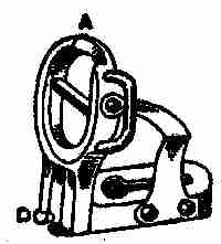
Fig. 97. Bobbin case holder
In some machines the bobbin case holder (Fig. 97) rests on the casting seen in Fig. 81. It is secured by a large set screw, D (Fig. 97). For general use, this screw should be adjusted to allow number 40 cotton to pass freely over the bobbin case. The holder should not be removed, except when adjustment or repair is needed. The vertical portion is hinged to the base, and is kept upright by a lock spring and stud. If the spring is pressed from the stud, the vertical or ring part can be drawn back for placing in or taking out the bobbin case. The face of this portion must be perfectly square with the bottom of the base, otherwise it may cause considerable trouble. A slight adjustment can be made by loosening the two screws and moving the lock spring. A set square, E, should be used for testing the accuracy of this part as shown (Fig. 98), F representing the bobbin case holder.
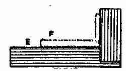
Fig. 98. Set square
The thread controller is similar in design to several others, but its movement is regulated by a small lever (Fig. 99) which receives its motion from a link attached to the foot bar bracket set screw, and this may be seen through a hole in the face plate. At G (Fig. 99), this lever engages with a stop washer located behind the thread controller plate. The washer is recessed to form a stop, at the same time to give sufficient clearance for the action of the spring; thus as the foot bar rises and falls, so does the thread controller spring. It is a common practice when cleaning a machine to remove the face plate, thus detaching the link referred to, and not connecting it again when replacing the face plate. From this, trouble arises. The tension pulley should be placed on its stud, the large boss being toward the face plate.
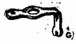
Fig. 99. Lever
Thread a machine as follows: From the reel pin to nipper F (Fig. 81), round tension pulley G as the arrow indicates, down and into thread controller H up to take-up lever, threading over the roll and through the slot from the top of lever, then down the thread guide J, into guide K, and through the needle-eye from right to left.
In the ordinary boat-shaped shuttle, the looping up of the thread is not difficult. The needle, as it descends, enters an opening or cavity in the carrier, one side of which forms a support for the needle and guards it from contact with the shuttle point. Now, it is important that there be clearance for the needle. If the carrier stands so prominent as to spring the needle out of its true vertical line it will carry it away from the shuttle, and give the latter a chance to miss the loop.
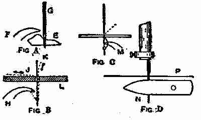
Fig. 100 A, B, C, D. Carriers and drivers
Then there are carriers and drivers of varying heights. Those of the raised kind are preferable, if properly fitted. By "raised" is meant that they are higher, so as to form a better guard for the needle, as previously referred to (Fig. 100 A, in which E indicates the portion of raised carrier, F the shuttle point, and G the needle). But sometimes they are too high, and permit the needle-eye to be buried in the carrier, thus preventing the proper formation of the loop. This can be so bad as to cause very frequent missing; or it may be of such a slight character as to cause a miss-stitch only now and then. Occasionally, a needle bar has to be lowered, and that is sufficient to cause the same fault. The eye of the needle should always be about one thirty-second of an inch above the upper edge of the carrier, and the latter should be shaped so as to allow that amount of clearance the whole of the time the needle is rising to form the loop, until the shuttle point has well entered the same. Fig. 100 B shows how a carrier is hollowed to give the necessary clearance to the needle eye.
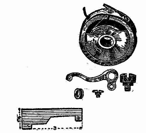
Fig. 101. Sewing machine items
When a machine is reasonably tight in all parts, gauges and setting marks may be adhered to for the preliminary adjustments; and then if the machine works erratically, other adjustments must be made. Where no marks or gauges are furnished for the adjustment of the needle bar, it should be so set as to allow the shuttle or hook to enter the bold part of the loop formed from the needle. A good rule is to set the needle bar so that the needle-eye is about 1⁄32 inch below the point of the shuttle M (Fig. 100 C) when the latter is up to the centre of the needle groove. But this may have to be varied from 1⁄64-inch to 3⁄32-inch. In boat-shaped and similar shuttle machines, a good rule is to set the needle so that the eye N will pass just below the lower side of the shuttle O as the latter is passing through the loop as in Fig. 100 D, P, indicating the level of the bed plate.
II MECHANICAL MOVEMENTS
What is meant by this term is that these devices are intended for the transmission of motion. Motion in mechanics may be simple or compound. Simple motions are those of straight translation, which if of indefinite duration must be reciprocating, or what is called oscillating or helical.
Compound motions consist of combinations of any of the simple motions. Perpetual motion is an incessant motion conceived to be attainable by a machine supplying its own motive forces independently of any action from without, or which has within itself the means, when once set in motion, of continuing its motion perpetually, or until worn out, without any new application of external force. The machine by means of which it has been attempted, or supposed possible to produce such motion, is an invention much sought after, but physically impossible.
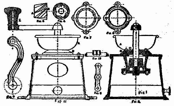
Fig. 102. Coffee mill and details
The illustrations herewith exhibit a number of devices of various kinds, well known to the practical mechanician and professional engineer, and usually called mechanical movements. It is estimated there are no less than 1,500 of these movements doing service at the present day; but many of them are, of course, quite complex, and difficult to master. In this book, I show about one hundred of the simplest sort, or those in common use. Their usefulness will at once be appreciated if we refer to Fig. 102, which shows a machine for grinding or breaking up substances within its capacity. It contains within itself the true principle of the little mill used to grind coffee. The word "grind" in this connection is scarcely the right one, as the mill rather "crushes" or breaks up, than grinds. You will notice coffee, ready for use, is coarse and unlike flour in texture, the latter being "ground" fine and smooth. In grinding, the abrading surfaces are brought very much closer together than in the breaking or crushing processes. In a coffee mill, the berries or grains drop into a vacancy, left between the revolving cone and the walls of the mill. The vacancy between the walls and the cone is a little less at the bottom where the crushed coffee is discharged, and this enables the small and large grounds to fall into the drawer. The detailed plan in illustration (Fig. 102) shows a mill complete, as well as the various parts. It will be noticed that the cone (Fig. 5), is corrugated or grooved as shown (Fig. 4). Figs. 6 and 7 show sections of lining at B and C (Fig. 3). A shows the hopper into which the coffee berries are placed before grinding. Figure 9 shows the crank detached, and Figs. 8 and 10 show the remaining parts of the machine, while Figs. 1 and 2 show the handle and drawer. The latter is to receive the ground or crushed coffee after it has gone through the mill. Further description is unnecessary if we take for example the movement represented at Fig. 150, which is a sort of ball-bearing motion, only instead of small balls wheels are used. Besides being made use of in bicycles in small balls, it is used as depicted for "hanging" grindstones, and for many other similar purposes.
The device also shown at Fig. 139, is one in common use. It is a modification of the sprocket wheel on the bicycle. Many of the devices shown herewith are rarely noticed because of our familiarity with them.
The action of pumps, the working of pistons, the changing of motion, and many other things are shown and explained in the little illustrations given in these descriptions, which do not pretend to be exhaustive, or even full.
Fig. 103. In this the lower pulley is movable. One end of the rope being fixed, the other has to move twice as fast as the weight, and a corresponding gain of power is consequently effected.
Fig. 104 is a simple pulley used for lifting weights. In this the power must be equal to the weight to obtain equilibrium.
Fig. 105. Blocks and tackle. The power obtained by this contrivance is calculated as follows: Divide the weight by double the number of pulleys in the lower block; the quotient is the power required to balance the weight.
Fig. 106 represents what are known as "White's pulleys", which can be made with separate loose pulley; or a series of grooves can be cut in a solid block, the diameters being made in proportion to the speed of the rope; that is, 1, 3, and 5 for one block, and 2, 4, and 6 for the other. Power as 1 to 7.
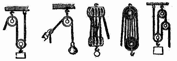
Figs. 103, 104, 105, 106, 107. Various phases of block and tackle
Figs. 107-108 are what are known as Spanish bartons.
Fig. 108 is a combination of two fixed and one movable pulley.
Figs. 111-113 are different arrangements of pulleys. The following rule applies to these: In a system of pulleys where each is embraced by a cord attached to one end of a fixed point, and at the other to the centre of the movable pulley, the effect of the whole will be the number 2 multiplied by itself as many times as there are movable pulleys in the system.
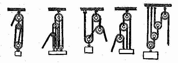
Figs. 108, 109, 110, 111, 112. Other combinations of blocks and pulleys
Fig. 114. Endless chain for maintaining power on going barrel, to keep a clock going while winding, as during that operation the action of the weight or mainspring is taken off the barrel. The wheel to the right is the going wheel, and that to the left the striking wheel. P is a pulley fixed to the great wheel of the going part, and roughened to prevent a rope or chain hung over it from slipping. A similar pulley rides on another arbour, p, which may be the arbour of the great wheel of the striking part, attached by a ratchet and click to that wheel, or to the clock frame if there is no striking part. The weights are hung as may be seen, the small one being only large enough to keep the rope or chain on the pulleys. If the part b of the rope or chain is pulled down, the ratchet-pulley runs under the click, and the great weight is pulled up by c, without taking its pressure off the going wheel at all.
Fig. 115. Triangular eccentric, giving an intermittent reciprocating rectilinear motion, often used for the valve motion of steam-engines.
Fig. 116. Ordinary crank-motion.
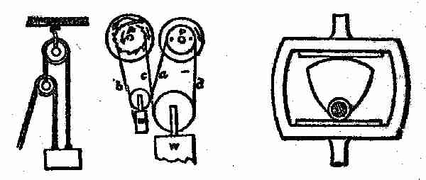
Figs. 113, 114, 115. Blocks and rocker
Fig. 117. In this, rotary motion is imparted to the wheel by the rotation of the screw, or rectilinear motion of the slide by the rotation of the wheel. Used in screw cutting and slide lathes.
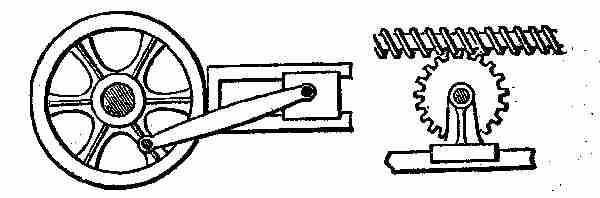
Figs. 116, 117. Crank and rotary motion
Fig. 118. Uniform circular into uniform rectilinear motion; used in spooling frames for leading or guiding the thread on to the spools. The roller is divided into two parts, each having a fine screw-thread cut upon it, one a right and the other a left-handed screw. The spindle, parallel with the roller, has arms which carry two half nuts, fitting to the screw, one over the other under the roller. When one half nut is in, the other is out of gear. By pressing the lever to the right or left the rod is made to traverse in either direction.
Fig. 119. A system of crossed levers, termed "lazy tongs." A short, alternating rectilinear motion of rod at the right will give a similar, but much greater motion to the rod at the left. It is frequently used in children's toys. It has been applied to machines for raising sunken vessels; also applied to ship pumps three quarters of a century ago.
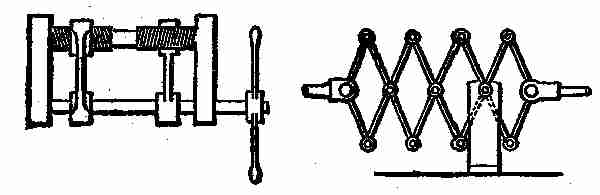
Figs. 118, 119. Rectilinear motion
Fig. 120. Centrifugal governor for steam engines. The central spindle and attached arms and balls are driven from the engine by the bevel gears at the top, and the balls fly out from the centre by centrifugal force. If the speed of the engine increases, the balls fly out from the centre, raise the slide at the bottom, and thereby reduce the opening of the regulating valve, which is connected with the slide. A diminution of speed produces an opposite effect.
Fig. 121. Water-wheel governor acting on the same principle as Fig. 120, but by different means. The governor is driven by the top horizontal shaft and bevel gears, and the lower gears control the rise and fall of the shuttle or gate over or through which the water flows to the wheel. The action is as follows: The two bevel gears on the lower part of the centre spindle, which are furnished with studs, are fitted loosely to the spindle, and remain at rest so long as the governor has a proper velocity; but immediately the velocity increases, the balls flying farther out, draw up the pin, which is attached to a loose sleeve which slides up and down the spindle, and this pin, coming in contact with the stud on the upper bevel gear, causes that gear to rotate with the spindle, and to give motion to the lower horizontal shaft in such a direction as to make it raise the shuttle or gate, and so reduce the quantity of water passing to the wheel. On the contrary, if the speed of the governor decreases below that required, the pin falls and gives motion to the lower bevel gear, which drives the horizontal shaft in the opposite direction, and produces a contrary effect.
Fig. 122. Another arrangement for a water-wheel governor. In this the governor controls the shuttle or gate by means of the cranked lever, which acts on the strap or belt in the following manner: The belt runs on one of three pulleys, the middle one of which is loose on the governor spindle, and the upper and lower ones fast. When the governor is running at the proper speed the belt is on the loose pulley, as shown; but when the speed increases, the belt is thrown on the lower pulley, and thereby caused to act upon suitable gearing for raising the gate or shuttle and decreasing the supply of water. A reduction of the speed of the governor brings the belt on the upper pulley, which acts upon the gearing for producing an opposite effect on the shuttle or gate.
Fig. 123. Another form of steam-engine governor. Instead of the arms being connected with a slide working on a spindle, they cross each other, are elongated upward beyond the top, and connected with the valve-rod by two short links.
Figs. 124, 125. Diagonal catch and hand-gear used in large blowing and pumping engines. In Fig. 124 the lower steam valve and upper eduction valves are open, while the upper steam valve and lower eduction valve are shut; consequently the piston is ascending. In the ascent of the piston rod the lower handle will be struck by the projecting tappet, and being raised will become engaged by the catch, so as to shut the upper eduction and lower steam valves; at the same time the upper handle will be disengaged from the catch, the back weight will pull the handle up and open the upper steam and lower eduction valves, when the piston will consequently descend. Fig. 125 represents the position of the catches and handles when the piston is at the top of the cylinder. In going down, the tappet of the piston rod strikes the upper handle, and throws the catches and handles to the position shown in Fig. 124.
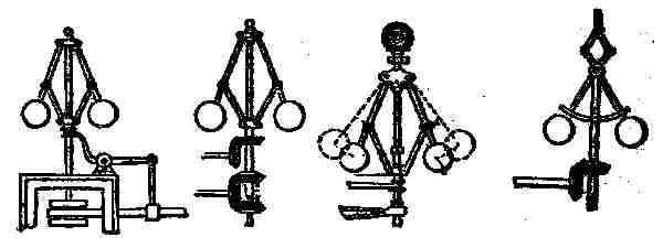
Figs. 120, 121, 122, 123. Governors for steam-engines
Fig. 126. A mode of driving a pair of feed rolls, the opposite surface of which require to move in the same direction. The two wheels are precisely similar, and both gear into the endless screw, which is arranged between them. The teeth of one wheel only are visible, those of the other being on the back or side which is concealed from view.
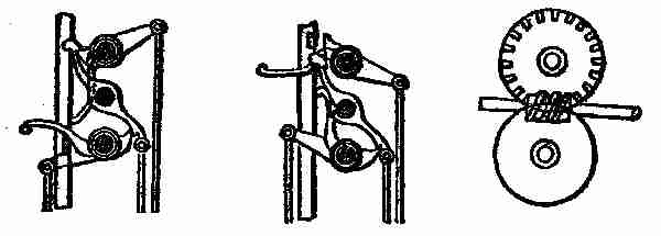
Figs. 124, 125, 126. Valve Regulation and Feed Rolls
Fig. 127. Link-motion valve gear of a locomotive; two eccentrics are used for one valve, one for the forward and the other for the backward movement of the engine. The extremities of the eccentric rods are jointed to a curved slotted bar, or, as it is termed, a link, which can be raised or lowered by an arrangement of levers terminating in a handle, as shown. In the slot of the link is a slide and pin connected with an arrangement of levers terminating in the valve stem. The link, in moving with the action of the eccentrics, carries with it the slide, and thence motion is communicated to the valve. Suppose the link raised so that the slide is in the middle, then the link will oscillate on the pin of the slide, and consequently the valve will be at rest. If the link is moved so that the slide is at one of the extremities, the whole throw of the eccentric connected with that extremity will be given to it, the valve and steam ports will be opened to the full, and it will only be toward the end of the stroke that they will be totally shut; consequently the steam will have been admitted to the cylinder during almost the entire length of each stroke. But if the slide is between the middle and the extremity of the slot, as shown in the figure, it receives only a part of the throw of the eccentric and the steam ports will only be partially opened, and quickly closed again, so that the admission of steam ceases some time before the termination of the stroke, and the steam is worked expansively. The nearer the slide is to the middle of the slot the greater will be the expansion, and vice versa.
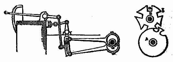
Figs. 127, 128. Link and other motions
Fig. 128 represents a mode of obtaining motion from rolling contact. The teeth are for making the motion continuous, or it would cease at the point of contact shown in the figure. The fork catch is to guide the teeth into proper contact.
Fig. 129. What is called the Geneva-stop, used in Swiss watches to limit the number of revolutions in winding-up; the convex curved part of the wheel serving as the stop.
Fig. 130. A continuous rotary motion of the large wheel gives an intermittent rotary motion to the pinion-shaft. The part of the pinion shown next the wheel is cut of the same curve as the plain portion of the circumference of the wheel, and therefore serves as a lock while the wheel makes a part of a revolution, and until the pin upon the wheel strikes the guide-piece upon the pinion, when the pinion-shaft commences another revolution.
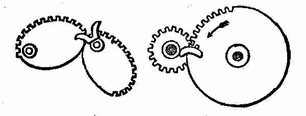
Figs. 129, 130. Stop and rotary motions
Fig. 131. The two crank-shafts are parallel in direction, but not in line with each other. The revolution of either will communicate motion to the other with a varying velocity, for the wrist of one crank working in the slot of the other is continually changing its distance from the shaft of the latter.
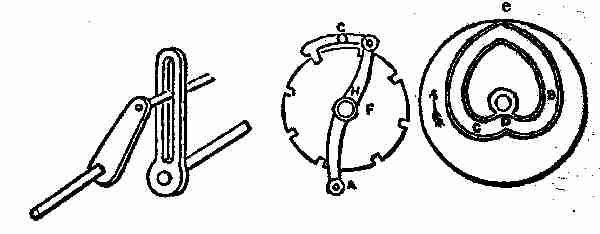
Figs. 131, 132, 133. Irregular Motions
Figs. 132 and 133. These are parts of the same movement, which has been used for giving the roller motion in wool-combing machines. The roller to which the wheel F, (Fig. 132) is secured, is required to make 1⁄3 revolution backward, then 2⁄3 revolution forward, when it must stop until another length of combed fibre is ready for delivery. This is accomplished by the grooved heart-cam C, D, B, e, (Fig. 133) the stud working in the said groove; from C to D it moves the roller backward, and from D to e it moves it forward, the motion being transmitted through the catch G, to the notch wheel F, on the roller-shaft H. When the stud A arrives at the point e in the cam, a projection at the back of the wheel, which carries the cam, strikes the projecting piece on the catch G, and raises it out of the notch in the wheel F, so that while the stud is travelling in the cam from e to C, the catch is passing over the plain surface between the two notches in the wheel F, without imparting any motion; but when stud A arrives at the part C, the catch has dropped in another notch and is again ready to move wheel F and roller as required.
Fig. 134. An arrangement for obtaining variable circular motion. The sectors are arranged on different planes, and the relative velocity changes according to the respective diameters of the sectors.
Fig. 135. Intermittent circular motion of the ratchet-wheel from vibratory motion of the arm carrying a pawl.
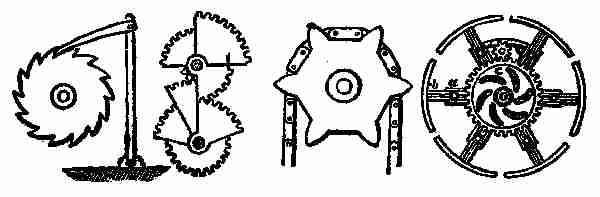
Figs. 135, 134, 137, 136. Movements of various kinds
Fig. 136. This represents an expanding pulley. On turning pinion d to the right or left, a similar motion is imparted to wheel c, by means of curved slots cut therein, which thrust the studs fastened to arms of pulley outward or inward, thus augmenting or diminishing the size of the pulley.
Fig. 137 represents a chain and chain pulley. The links being in different planes, spaces are left between them for the teeth of the pulley to enter.
Fig. 138. Another kind of chain and pulley.
Fig. 139. Another variety.
Fig. 140 shows two different kinds of stops for a lantern-wheel.
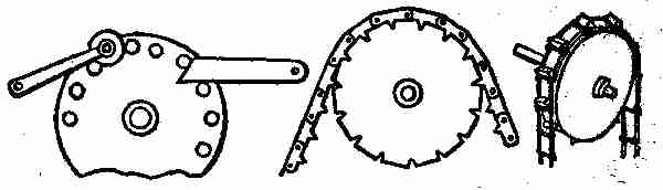
Figs. 140, 138, 139. Chain pulleys and lantern-wheel
Fig. 141. Intermittent circular motion is imparted to the toothed wheel by vibrating the arm B. When the arm B is lifted, the pawl C is raised from between the teeth of the wheel, and travelling backward over the circumference again drops between two teeth on lowering the arm, and draws with it the wheel.
Fig. 142. The oscillating of the tappet-arm produces an intermittent rotary motion of the ratchet-wheel. The small spring at the bottom of the tappet-arm keeps the tappet in the position shown in the drawing, as the arm rises, yet allows it to pass the teeth on the return motion.
Fig. 143. A nearly continuous circular motion is imparted to the ratchet-wheel on vibrating the lever a to which the two pawls b and c are attached.
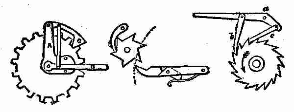
Figs. 141, 142, 143. Intermittent circular motion
Fig. 144. An arrangement of stops for a spur-gear.
Fig. 145. A reciprocating circular motion of the top arm makes its attached pawl produce an intermittent circular motion of the crown-ratchet, or ray-wheel.
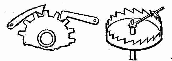
Figs. 144, 145. Intermittent circular motion
Fig. 146 represents varieties of stops for ratchet-wheel.
Fig. 147. Intermittent circular motion is imparted to the wheel A by the continuous circular motion of the smaller wheel with one tooth.
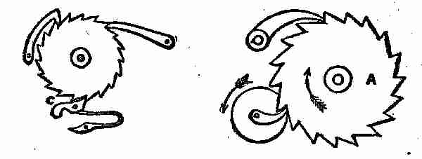
Figs. 146, 147. Ratchet motion
Fig. 148. A dynamometer, or instrument used for ascertaining the amount of useful effect given out by any motive power. It is used as follows: A is a smoothly turned pulley, secured on a shaft as near as possible to the motive power. Two blocks of wood are fitted to this pulley, or one block of wood and a series of straps fastened to a band or chain, as in the drawing, instead of a common block. The blocks, or block and straps, are so arranged that they may be made to bite or press upon the pulley by means of the screws and nuts on the top of the lever D. To estimate the amount of power transmitted through the shaft, it is only necessary to ascertain the amount of friction of the drum A when it is in motion, and the number of revolutions made. At the end of the lever D is hung a scale B, in which weights are placed. The two stops C C are to maintain the lever as nearly as possible in a horizontal position. Now, suppose the shaft to be in motion, the screws are to be tightened and weights added in B, until the lever takes the position shown in the drawing, at the required number of revolutions. Therefore the useful effect would be equal to the product of the weights, multiplied by the velocity at which the point or suspension of the weights would revolve if the lever were attached to the shaft.
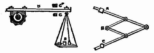
Figs. 148, 149. Dynamometer—Pantagraph
Fig. 149 represents a pantagraph for copying, enlarging and reducing plans. One arm is attached to and turns on the fixed point C. B is an ivory tracing point, and A the pencil. Arranged as shown, if we trace the lines of a plan with the point B, the pencil will produce it double the size. By shifting the slide attached to the fixed point C and the slide carrying the pencil along their respective arms, the proportions to which the plan is traced will be varied.
Fig. 150. Anti-friction bearing. Instead of a shaft revolving in an ordinary bearing, it is sometimes supported on the circumference of wheels. The friction is thus reduced to the least amount.
Fig. 151. Releasing hook used in pile-driving machines. When the weight W is sufficiently raised, the upper ends of the hooks A, by which it is suspended, are pressed inward by the side of the slot B, in the top of the frame; the weight is thus suddenly released, and falls with accumulating force on to the pile-head.
Fig. 152. A and B are two rollers which require to be equally moved to and fro in the slot C. This is accomplished by moving the piece D, with oblique slotted arms, up and down.
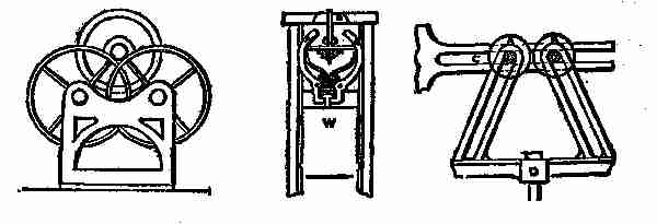
Figs. 150, 151, 152. Anti-friction—Drop hook—Regular motion
Fig. 153. Centrifugal check-hooks, for preventing accidents in case of the breakage of machinery which raises and lowers workmen, or ores, in mines. A is a framework fixed to the side of the shaft of the mine, and having fixed studs D, attached. The drum on which the rope is wound is provided with a flange B, to which the check-hooks are attached. If the drum acquires a dangerously rapid motion, the hooks fly out by centrifugal force, and one or other, or all of them, catch hold of the studs D, arrest the drum, and stop the descent of whatever is attached to the rope. The drum ought besides this, to have a spring applied to it, otherwise the jerk arising from the sudden stoppage of the rope might produce a worse effect than its rapid motion.
Fig. 154. A sprocket-wheel to drive or to be driven by a chain.
Fig. 155. A combination movement, in which the weight W moves with a reciprocating movement, the down-stroke being shorter than the up-stroke. B is a revolving disc, carrying a drum which winds around itself the cord D. An arm C is jointed to the disc and to the upper arm A, so that when the disc revolves, the arm A moves up and down, vibrating on the point G. This arm carries with it the pulley E. Suppose we detach the cord from the drum, tie it to the fixed point, and then move the arm A up and down. The weight W will move the same distance, and in addition the movement given it by the cord, that is to say, the movement will be doubled. Now, let us attach the cord to the drum, and revolve the disc B, and the weight will move vertically with the reciprocating motion, in which the down-stroke will be shorter than the up-stroke, because the drum is continually taking up the cord.
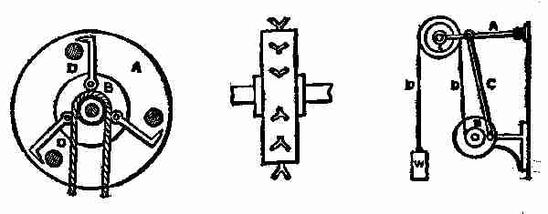
Figs. 153, 154, 155. Hooks—Sprocket—Combination movement
Figs. 156, 157. The first of these figures is an end view, and the second is a side view of an arrangement or mechanism for obtaining a series of changes in velocity and direction. D is a screw on which is placed eccentrically the cone B, and C is a friction roller, which is pressed against the cone by a spring or weight. Continuous rotary motion, at a uniform velocity of the screw D carrying the eccentric cone, gives a series of changes of velocity and direction to the roller C. It will be understood that during every revolution of the cone the roller would press against a different part of the cone, and that it would describe thereon a spiral motion, the movement in one direction being shorter than that in the other.
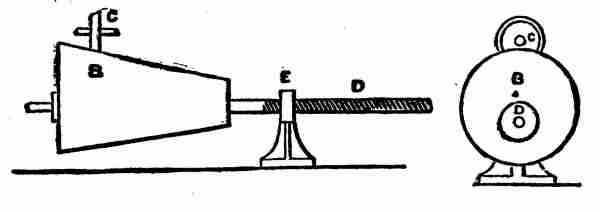
Figs. 156, 157. Change of speed
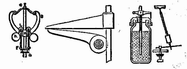
Fig. 158. An engine governor. The rise and fall of the balls K are guided by the parabolic curved arms B, on which the anti-friction wheels L run. The rods F, connecting the wheel L with the sleeve, move it up and down the spindle C D.
Fig. 159. Toe and lifter for working poppet-valves in steam engines. The curved toe on the rock-shaft operates on the lifter attached to the lifting rod to raise the valve.
Fig. 160. Mercurial compensation pendulum. A glass jar of mercury is used for the bob or weight. As the pendulum-rod is expanded lengthwise by increased temperature, the expansion of mercury in the jar carries it to a greater height therein, and so raises its centre of gravity relatively to the rod sufficiently to compensate for downward expansion of the rod. As rod is contracted by a reduction of temperature, contraction of mercury lowers it relatively to rod. In this way the centre of oscillation is always kept in the same place, and the effective length of pendulum always the same.
Figs. 158, 159, 160. Governor, lifter, and pendulum
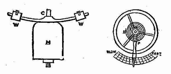
Fig. 161. Compound bar compensation pendulum. C is a compound bar of brass and iron, or steel brazed together with brass downward. As brass expands more than iron, the bar will bend upward as it gets warmer, and will carry the weights W, W, up with it, raising the centre of the aggregate weight M, to raise the centre of oscillation as much as elongation of the pendulum-rod would let it down.
Fig. 162. Watch regulator. The balance-spring is attached at its outer end to a fixed stud R, and at its inner end to staff of balance. A neutral point is formed in the spring at P, by inserting it between two curb-pins in the lever, which is fitted to turn on a fixed ring concentric with staff of balance, and the spring only vibrates between this neutral point and staff of balance. By moving lever to the right, the curb-pins are made faster, and by moving it to the left, an opposite effect is produced.
Figs. 161, 162. Compound bar—Hair spring
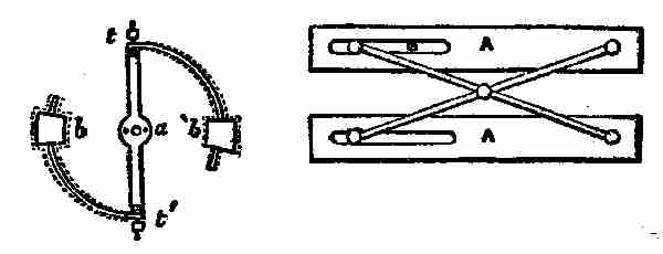
Fig. 163. Compensation balance. t, a, t´ is the main bar of balance, with timing screws for regulation at the ends. t and t´ are two compound bars, of which the outside is brass and the inside steel, carrying weights b, b´. As heat increases, these bars are bent inward, diminishing the inertia of the balance. As the heat diminishes, an opposite effect is produced. This balance compensates both for its own expansion and contraction, and that of the balance-spring.
Fig. 164. Parallel ruler, consisting of a simple straight ruler B, with an attached axle C, and a pair of wheels A A. The wheels, which protrude but slightly through the under side of the ruler, have their edges nicked to take hold of the paper and keep the ruler always parallel with any lines drawn upon it.
Figs. 163, 164. Balance—Ruler
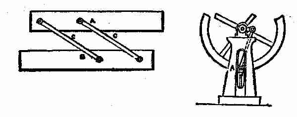
Fig. 165. Compound parallel ruler, composed of two simple rulers A, A, connected by two crossed arms pivoted together at the middle of their length, each pivoted at one end to one of the rulers, and connected with the other one by a slot and sliding pin, as shown at B. In this the ends as well as the edges are kept parallel. The principle of construction of the several rulers represented is taken advantage of in the formation of some parts of machinery.
Fig. 166. A simple means of guiding or obtaining a parallel motion of the piston rod of an engine. The slide a moves in and is guided by the vertical slot in the frame, which has been planed to a true surface.
Figs. 165, 166. Ruler—Parallel motion
Fig. 167. Parallel motion for direct-action engines. In this, the end of the bar B C is connected with the piston-rod, and the end B slides in a fixed slot D. The radius bar F A is connected at F with a fixed pivot, and at A midway between the ends of B C.
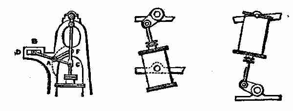
Figs. 167, 168, 169. Parallel motion methods
Fig. 168. Oscillating engine. The cylinder has trunnions at the middle of its length, working in fixed bearings, and the piston rod is connected directly with the crank, and no guides are used.
Fig. 169. Inverted oscillating or pendulum engine. The cylinder has trunnions at its upper end, and swings like a pendulum. The crank shaft is below, and the piston rod connected directly with crank.
Fig. 170. Section of disc-engine. Disc-piston, seen edgewise, has a motion substantially like a coin when it first falls after being spun in the air. The cylinder heads are cones. The piston rod is made with a ball to which the disc is attached, said ball working in concentric seats in cylinder-heads, and the left-hand end is attached to the crank arm or fly-wheel on end of shaft at left. Steam is admitted alternately on either side of piston.
Fig. 171. The gyroscope, or rotascope, an instrument illustrating the tendency of rotating bodies to preserve their plane of rotation. The spindle of the metallic disc C is fitted to return easily in bearings in the ring A. If the disc is set in rapid rotary motion on its axis, and the pintle F at one side of the ring A is placed on the bearing in the top of the pillar G, the disc and ring seem indifferent to gravity, and instead of dropping begin to revolve about the vertical axis.
Fig. 172. Bohnenberger's machine, illustrating the same tendency of rotating bodies. This consists of 3 rings, A, A´, A2, placed one within the other, and connected by pivots at right angles to each other. The smallest ring, A2, contains the bearings for the axis of a heavy ball B. The ball being set in rapid rotation, its axis will continue in the same direction, no matter how the position of the rings may be altered; and the ring A2, which supports it, will resist a considerable pressure tending to displace it.
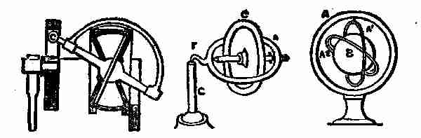
Figs. 170, 171, 172. Disc-engine and gyroscopes
Fig. 173. What is called the gyroscope governor, for steam-engines, introduced by Alban Anderson in 1858. A is a heavy wheel, the axle B B´ of which is made in two pieces connected together by a universal joint. The wheel A is on one piece B, and a pinion I on the other piece B´. The piece B is connected at its middle by a hinge-joint with the revolving frame H, so that variations in the inclination of the wheel A will cause the outer end of the piece B to rise and fall. The frame H is driven by bevel gearing from the engine, and by that means the pinion 1 is carried round the stationary toothed circle G, and the wheel A is thus made to receive a rapid rotary motion on its axis. When the frame H and wheel A are in motion, the tendency of the wheel A is to assume a vertical position, but this tendency is opposed by a spring L. The greater velocity of the governor, the stronger the tendency, above mentioned, and the more it overcomes the force of the spring, and the reverse. The piece B is connected with the valve rods by rods C, D, and the spring L is connected with the said rods by levers N and rod P.
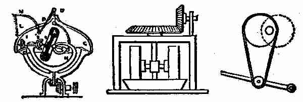
Figs. 173, 174, 175. Governor—Reverse motions
Fig. 174. Pair of edge runners or chasers for crushing or grinding. The axles are connected with vertical shaft, and the wheel or chasers run in an annular pan or trough.
Fig. 175. Rotary motion of shaft from treadle by means of an endless band running from a roller on the treadle to an eccentric on the shaft.
Fig. 176. Tread-wheel horse-power turned by the weight of an animal attempting to walk up one side of its interior; has been used for driving the paddle-wheels of ferry-boats and many other purposes. The turn-spit dog used also to be employed in such a wheel in ancient times for turning meat while roasting on a spit.
Fig. 177. The treadmill, employed in jails in some countries for exercising criminals condemned to labour, and employed in grinding grain; turns by weight of person stepping on tread-boards on periphery. This is supposed to be a Chinese invention, and it is still used in China for raising water for irrigation.
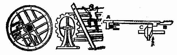
Figs. 176, 177, 178. By different sources of power
Fig. 178. A. B. Wilson's four-motion feed, used in Wheeler and Wilson's, Sloat's, and other sewing machines. The bar A is forked, and has a second bar B, carrying the spur or feeder, pivoted in the said fork. The bar B is lifted by a radial projection on the cam C, at the same time the two bars are carried forward. A spring produces the return stroke, and the bar B drops of its own gravity.
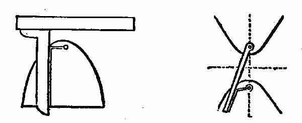
Fig. 179. Mechanical means of describing parabolas, the base, altitude, focus, and directrix being given. Lay straight edge with near side coinciding with directrix, and square with stock against the same, so that the blade is parallel with the axis, and proceed with pencil in bight of thread, as in the preceding.
Figs. 179, 180. To describe conic sections
Fig. 180. Mechanical means of describing hyperbolas, their foci and vertices being given. Suppose the curves two opposite hyperbolas, the points in vertical dotted centre line their foci. One end of thread being looped on pin inserted at the other focus, and other end held to other end of rule, with just enough slack between to permit height to reach vertex when rule coincides with centre line. A pencil held in bight, and kept close to the rule, while latter is moved from centre line, describes one-half of parabola; the rule is then reversed for the other half.
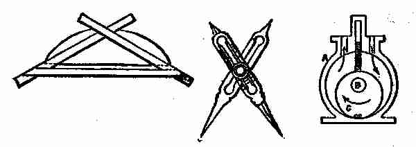
Fig. 181. Cyclograph for describing circular arcs in drawings where the centre is inaccessible. This is composed of three straight rules. The cord and versed sine being laid down, draw straight, sloping line from ends of former to top of latter; and to these lines lay two of the rules crossing at the apex. Fasten these rules together, and another rule across them to serve as a brace, and insert a pin or point at each end of chord to guide the apparatus, which, on being moved against these points, will describe the arc by means of pencil in the angle of the crossing edges of the sloping rules.
Fig. 182. Proportional compasses used in copying drawings on a given larger or smaller scale. The pivot of compasses is secured in a slide which is adjustable in the longitudinal slots of legs, and capable of being secured by a set screw; the dimensions are taken between one pair of points and transferred with the other pair, and thus enlarged or diminished in proportion to the relative distances of the points from the pivot. A scale is provided on one or both legs to indicate the proportions.
Fig. 183. One of the many forms of rotary engine. A is a cylinder having the shaft B pass centrally through it. The piston C is simply an eccentric fast on the shaft, and working in contact with the cylinder at one point. The induction and eduction of steam take place as indicated by arrows, and the pressure of the steam on one side of the piston produces its rotation and that of the shaft. The sliding abutment D, between the induction and eduction ports, moves out of the way of the piston to let it pass.
Figs. 181, 182, 183. For drawing curves. Rotary engine
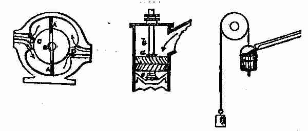
Fig. 184. Another form of rotary engine, in which there are two stationary abutments D, D, within the cylinder; and the two pistons A, A, in order to enable them to pass the abutments, are made to slide radially in grooves in the hub C of the main shaft B. The steam acts on both pistons at once, to produce the rotation of the hub and shaft. The induction and eduction are indicated by arrows.
Fig. 185. Jonval turbine. The shutes are arranged on the outside of a drum, radial to a common centre, and stationary within the trunk or casing b. The wheel c is made in nearly the same way; the buckets exceed in number those of the shutes, and are set at a slight tangent instead of radially, and the curve generally used is that of the cycloid or parabola.
Fig. 186. A method of obtaining a reciprocating motion from a continuous fall of water, by means of a valve in the bottom of the bucket which opens by striking the ground, and thereby emptying the bucket, which is caused to rise again by the action of a counterweight on the other side of the pulley over which it is suspended.
Figs. 184, 185, 186. Different forms of water movements
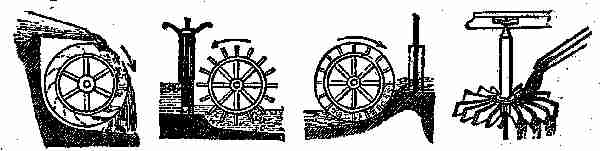
Fig. 187. Overshot water-wheel.
Fig. 188. Undershot water-wheel.
Fig. 189. Breast-wheel. This holds intermediate place between overshot and undershot wheels; has float-boards like the former, but the cavities between are converted into buckets by moving in a channel adapted to circumference and width, into which water enters nearly at the level of axle.
Fig. 190. Horizontal overshot water-wheel.
Figs. 187, 188, 189, 190. Water-wheels
Fig. 191. A plan view of the Fourneyron turbine water-wheel. In the centre are a number of fixed curved chutes, or guides, A, which direct the water against the buckets of the outer wheel B, which revolves, and the water discharges at the circumference.
Fig. 192. Warren's central discharge turbine, plan view. The guides A are outside, and the wheel B revolves within them, discharging the water at the centre.
Fig. 193. Volate wheel, having radial vanes A, against which the water impinges and carries the wheel around. The scroll or volute casing B confines the water in such a manner that it acts against the vanes all around the wheel. By the addition of the inclined buckets c, c, at the bottom, the water is made to act with additional force as it escapes through the openings of said buckets.
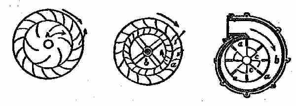
Figs. 191, 192, 193. Central discharge and turbine wheels
Fig. 194. Barker, or reaction mill. Rotary motion of central hollow shaft is obtained by the reaction of the water escaping at the ends of its arms, the rotation being in a direction the reverse of the escape.
Fig. 195 represents a trough divided transversely into equal parts, and supported on an axis by a frame beneath. The fall of water filling one side of the division, the trough is vibrated on its axis, and at the same time that it delivers the water the opposite side is brought under the stream and filled, which in like manner produces the vibration of the trough back again. This has been used as a water-meter.
Fig. 196. Persian wheel, used in Eastern countries for irrigation. It has a hollow shaft and curved floats, at the extremities of which are suspended buckets or tubs. The wheel is partly immersed in a stream acting on the convex surface of its floats; and as it is thus caused to revolve, a quantity of water will be elevated by each float at each revolution, and conducted to the hollow shaft at the same time that one of the buckets carries it full of water to a higher level, where it is emptied by coming in contact with a stationary pin placed in a convenient position for tilting it.
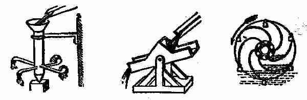
Figs. 194, 195, 196. Water motors
Fig. 197. Machine of ancient origin, still employed on the river Eisach, in the Tyrol, for raising water. A current keeping the wheel in motion, the pots on its periphery are successively immersed, filled, and emptied into a trough above the stream.
Fig. 198. Application of Archimedes screw for raising water, the supply stream being the motive power. The oblique shaft of the wheel has extending through it a spiral passage, the lower end of which is immersed in water, and the stream acting upon the wheel at its lower end produces its revolution by which the water is conveyed upward continuously through the spiral passage and discharged at the top.
Fig. 199. Common lift pump. In the upper-stroke of piston or bucket the lower valve opens and the valve in piston shuts; air is exhausted out of suction pipe, and water rushes up to fill the vacuum. In down stroke lower valve is shut and valve in piston opens, and the water simply passes through the piston. The water above piston is lifted up, and runs over out of spout at each up stroke. This pump cannot raise water over thirty feet high.
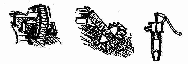
Figs. 197, 198, 199. Water-wheels and pumps
Fig. 200. Ordinary force pump, with two valves. The cylinder is above water, and is fitted with solid piston; one valve closes outlet pipe, and other closes suction pipe. When piston is rising suction-valve is open, and water rushes into cylinder, outlet valve being closed. On descent of piston suction valve closes, and water is forced up through outlet valve to any distance or elevation.
Fig. 201. Double-acting pump. Cylinder closed at each end, and piston-rod passes through stuffing-box on one end, and the cylinder has four openings covered by valves, two for admitting water and like number for discharge. A is suction pipe, and B discharge pipe. When piston moves down, water rushes in at suction valve 1, on upper end of cylinder, and that below piston is forced through valve 3 and discharge pipe B; on the piston ascending again, water is forced through discharge valve 4, on upper end of cylinder, and water enters lower suction valve 2.
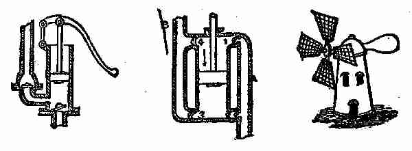
Figs. 200, 201, 202. Pumps and windmill
Fig. 202. Common windmill, illustrating the production of circular motion by the direct action of the wind upon the oblique sails.
Fig. 203. Ordinary steering apparatus. Plan view. On the shaft of the hand wheel, there is a barrel on which is wound a rope, which passes round the guide-pulleys, and has its opposite ends attached to the tiller, or lever, on top of the rudder; by turning the wheel, one end of the rope is wound on and the other left off, and the tiller is moved in one or the other direction, according to the direction in which the wheel is turned.
Fig. 204. Capstan. The cable or rope wound on the barrel of the capstan is hauled in by turning the capstan on its axis by means of handspikes or bars inserted into holes in the head. The capstan is prevented from turning back by a pawl attached to its lower part and working in a circular ratchet on the base.
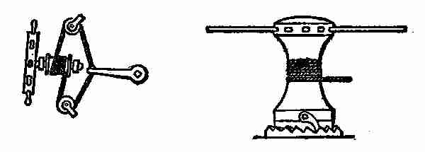
Fig. 203. Cable Fig. 204. Capstan
Fig. 205. Lewis bolt for lifting stone in building. It is composed of a central taper-pin or wedge, with two wedge-like packing pieces arranged one on each side of it. The three pieces are inserted together in a hole drilled into the stone, and when the central wedge is hoisted upon it, it wedges the packing pieces out so tightly against the sides of the hole as to enable the stone to be lifted.
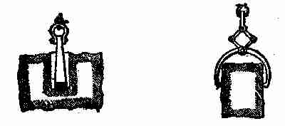
Figs. 205, 206. Lewis bolts, for lifting stones
Fig. 206. Tongs for lifting stones. The pull on the shackle which connects the two links causes the latter so to act on the upper arms of the tongs as to make their points press themselves against or into the stone. The greater the weight, the harder the tongs bite.
III THE WEATHER AND INDOOR WORK
The measure of rainfall varies considerably within comparatively small areas, and this renders it no easy matter to get correct figures, so that the nearest records are those taken from a number of gauges within a limited district, and generalized. The more this is done, the less will be the inaccuracy in referring to the rainfall of any particular district or country.
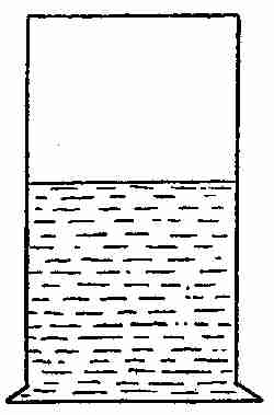
Fig. 207. Rain-gauge
If numerous rain-gauges were established throughout the country, and all their records sent to one central station, what valuable information might be collected for a particular district or country in the course of years. Means might be found for using the superabundant water, which falls in one part over another part, where the rainfall is less. Information such as this might be of special value in the West and South. It is collected now to a certain extent; but not done so generally as it ought to be.
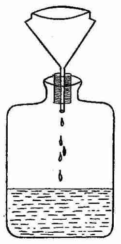
Fig. 208. A made rain-gauge
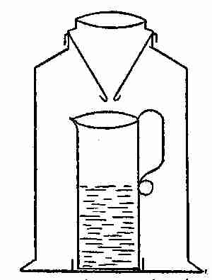
Fig. 209. A more complete rain-gauge
As the fall of rain is always measured in inches gauges are made to indicate the equivalent of a cubic inch of rain on the surface of the earth. The simplest form of rain-gauge is a square or circular box or jar with a perfectly flat bottom and perpendicular sides (see Fig. 207). If the depth of water in such a gauge be measured after a fall of rain, one can ascertain in inches, or parts of an inch, the amount of rain that has fallen on the surface of the earth. Care must be taken to have the edge of the gauge thin and free from dents, the sides perpendicular and the bottom of the jar perfectly flat, for though in one measurement these irregularities may not make much difference, they would lead to a very decided error in a large number of measurements. Evaporation is also liable in such a gauge to give rise to errors, and extraneous matters are easily introduced. The better rain-gauges are constructed to avoid these contingencies, as far as possible and to depend only on the area of entry for the accuracy of the measurements. This area may be a square, but is usually circular for convenience. The circle must be accurate, and its area is then easily calculated, so that one can estimate the amount of rainfall, however large the receiving vessel may be. The edge of the circle, which may be made of copper, more durable than iron, must be sharp, with an overlapping rim to prevent raindrops from being whirled out of the receiver, and connected by a shoulder to a funnel, which directs the water into the receiver. This may be a glass bottle fitted with a cork to hold the funnel firmly, and prevent leakage between the outside of the funnel and the neck of the bottle (see Fig. 208). A more convenient receiver, and one less likely to be broken, is a round tin case of convenient size, with a top fitting accurately under the overlapping edge of the funnel-shaped cover. In this large receiver may be placed a small tin mug, with a lip just under the funnel, for conveniently measuring small quantities of rain, and preventing waste by evaporation. Any overflow from the mug will be caught in the large receiver (see Fig. 209). The circle of entry may, of course, be of any size; but one whose diameter is between 4 or 8 inches will be most convenient. Make the circle determine its area by careful measurement, using the following formula: D2 × .7854 = area, each square inch will give cubic inches for area. Take this amount of water and pour it into a glass, marked at the top of the water, and then divide the intervening space between this mark and the bottom into 100 equal parts. This graduated glass will give the rainfall in inches and 100ths of an inch. As an inch glass is somewhat cumbersome, a half-inch glass is usually sent out with a rain-gauge. It may, however, be sometimes convenient to use an ordinary ounce measure, as graduated glass measures, when broken, are not always easily replaced; so that it may be necessary to find the corresponding relation between the cubic inches of receiving area and ounces and drachms. To do this, we will suppose the diameter of the circular top of gauge to be 4.7 inch; this squared = 22.09, multiplied by .7854 = 17.349486, divided by 1.733 (an ounce avoir. = 1.733 c. in.) = 10.011 oz. avoir.
Now if the rainfall is collected daily at a certain time in an ounce measure, the amount may easily be recorded in inches by reference to the accompanying table:
inch inch
10 oz. =1.0000 1 oz. = .1000
9 " = .9000 7 dr. = .0875
8 " = .8000 6 " = .0750
7 " = .7000 5 " = .0625
6 " = .6000 4 " = .0500
5 " = .5000 3 " = .0375
4 " = .4000 2 " = .0250
3 " = .3000 1 " = .0125
2 " = .2000
A similar calculation can be made and table prepared for any larger circle of entry by the same method.
The amount of rainfall in any country is a matter of great importance to that country, and, like the rise of the Nile in Egypt, it indicates the coming state of the crops. If we have too small a rainfall, drought and withered crops follow, and if we get too great a fall of rain, drowned out crops, and disastrous floods occur, so you see how necessary it is that those people who are elected to look after the welfare of a nation, should keep posted on matters of rainfall in all its phases. In India, China and some other parts of the world the question of rainfall is one of life and death to the people, and most of the great famines of the past have been due to the small rainfall. Hundreds of thousands of people used to perish by famine and disease year after year. Much of this danger from shortage of rain has happily been avoided in India by the efforts of the British government, which has inaugurated and carried out great schemes of irrigation and artificial waterways to prevent the recurrence of famine from drought. Our own government also is expending large sums of money on irrigation plans now being executed in Arizona, Texas, Colorado and other states, which will render immense territories fit for cultivation, which would otherwise have remained barren and of no use. The matter of rainfall is of the highest importance to a nation and to the men and beasts inhabiting it.
"Will it rain to-day?" is a question frequently asked, as regards the weather, showing how important the subject is, and while I am talking on it, it may not be amiss to make a few remarks regarding the formation and distribution of rain, as formulated by learned meteorologists. We are told that the two great causes of rain are the sun and the ocean—the latter, of course, includes the great lakes and rivers—and since these two factors may be taken as constant, it follows that the rainfall over the earth as a whole will always be constant, while the local variations will be due to local conditions. The rain which falls on this continent is drawn up by the sun from the various sources, but the conditions which cause its precipitation may be said to be local. To your imagination may be left the tracing of the journey of the rain drops back to the ocean again. The starting points in considering the causes of rain are, therefore, heat and moisture. From the surface of land and water moisture is continually evaporating into the atmosphere, and the higher the temperature of the air the more watery particles it can hold. If any reduction in the temperature of this saturated air should take place, the vapour becomes visible as fog, mist, or cloud, and it is from this vapour that the rain drops are formed. Recent research says that these watery particles require minute dust atoms as nuclei before they can form, and it has been estimated, by experiment, that there are one thousand millions of them in a cubic foot of saturated air, though their total weight amounts to only 3 grains. Accepting these figures, the mathematically inclined may be told that it would require a cloud three miles thick to produce one inch of rainfall. But before these watery particles can fall to the earth as rain, they must first form into rain drops, and the question arises, how are rain drops formed?
These watery particles pass into the air by evaporation, and there are several ways by which the reduction in temperature necessary to render them visible can be brought about. It may take place through contact with a colder body of air, by expansion, or by a reduction of pressure owing to a rise in altitude. Clouds are said to be formed by this last method, for a volume of hot air rises higher and higher until it presently reaches a point when its contained vapour condenses, and becomes visible as a cloud. Meteorologists repeat one of these processes in the laboratory, by releasing from pressure damp air placed in a convenient glass globe, and are able to see something of the methods of cloud formation. It has been customary to speak of a cloud as being composed of watery particles floating motionless in the upper air; but although it may appear unchanged in form, it is all movement. So soon as ever a cloud is formed, its particles of moisture commence to fall slowly, the rate of fall being in proportion to the diameter of the particles, and this is due to the slight resistance the air makes to such very small atoms. In passing, it may be said that one observer estimates the diameter of these particles as from .00033 inch to .00025 inch. The component parts of a cloud are always in motion and recognizing this fact it becomes possible to take the first step in considering the formation of a raindrop.