PART I (continued 2)
Reading edition
In the evening Mr. Gregg asked the boys and Jessie to visit his room, and he would try to explain the principle and advantages of the wheel and axle, as the winch they were to make was in a measure related to that principle. Mr. Gregg began by saying: "The wheel and axle is merely a modification of the lever and consists of a couple of cylinders turning on a common axis, the larger cylinder is usually called the wheel, the lesser one the axle. This arrangement, which I draw on the blackboard herewith, forms a kind of lever of the first or second class. Considered as a lever, the fulcrum is at the common axis, while the arms of the lever are the radii of the wheel and of the axle.
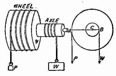
Fig. 20. Wheel and axle
"The fulcrum is at C, the centre. The arm of the weight is W W, and the arm of the power is A C. In Fig. 20 the arm of the power is the spoke of the wheel, while the arm of the weight is the radius of the axle. Fig. 19 shows the ordinary winch, often used in well-digging for hauling up dirt and rock, and also for raising planks, shingles, rafters, and other light stuff, to the roofs and upper floors of buildings. Often it is made more powerful by adding spur or geared wheels to the end of the shaft, consisting of a pinion and a larger spurred wheel. The crank or handle is attached to the pinion, and the power is increased according to the difference in diameters of the spur wheels. The machine is then called a 'crab' and it is often used for lifting safes and other heavy weights to elevated situations. In Fig. 20 the length of the crank (in a straight line) is the arm of the power.
"The mechanical advantage of the wheel and axle equals the ratio between the diameter of the wheel and of the axle.
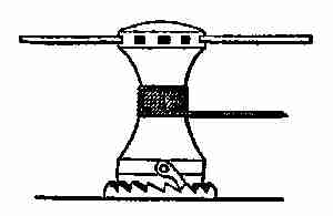
Fig. 21. Capstan and hand bars
"It is not necessary that an entire wheel be present. In the case of the windlass and the capstan (Fig. 21), the power may be applied to a single arm or to a number of arms placed in the holes shown. The cable or rope on the barrel of the capstan is hauled in by turning the capstan on its axis, with handspikes or bars. The capstan is prevented from turning back by a pawl attached to its lower part, working in a circular ratchet on the base.
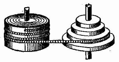
Fig. 22. Compensating fusee
"As an illustration of the lever action, and of work put into and got out of a machine, there is no better illustration than the ingenious contrivance termed the fusee (Fig. 22). In good watches and clocks, where the elastic force of a coiled spring is used to drive the works, the fusee compensates the gradually diminishing pull of the uncoiling spring. The driving of the works at a constant rate is the object for which a watch or clock is designed. This usually entails a constant resistance to be overcome, but since one of the most compact and convenient forms of mechanism into which mechanical force can be stored is that of the coiled spring, and since the very nature of the spring is such that its force decreases as it uncoils, we must employ some compensating device between this variable driving force and the constant resistance. The fusee does this in a most accurate and complete manner. As the fusee to the right is to compensate for the loss of force of the spring as it uncoils itself, the chain is on the small diameter of the fusee when the watch is wound up, as the spring has then the greatest force.
"In the differential, or Chinese windlass (Fig. 23), different parts of the cylinder have different diameters, the rope winding upon the larger and unwinding from the smaller. By one revolution the load is lifted a distance equal to the difference between the circumference of the two parts.
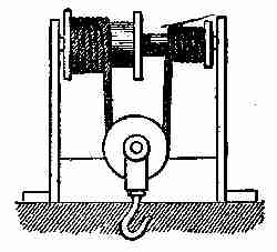
Fig. 23. Chinese winch and pulley
"There are many other contrivances and appliances of the wheel and axle for performing various services, but I think the examples I have shown you will be sufficient to enable you to make use of the device to perform any duty you may be called upon to attempt in ordinary life, but, should you enter professional life as civil, mechanical, naval, or mining engineer or architect, you will be obliged to pursue the study of these subjects further.
"Before closing I may add a few problems for you to solve at your leisure by the application of the rules I have given you when describing the other mechanical powers.
"The pilot wheel of a boat is 3 feet in diameter; the axle is 6 inches; the resistance of the rudder is 240 pounds. What power applied to the wheel will move the rudder? Here the difference between the axle and wheel is 18 inches.
"Four men are hoisting an anchor of 3,000 pounds' weight; the barrel of the capstan is 8 inches in diameter; the circle described by the handspikes is 7 feet 6 inches in diameter. How great a pressure must each of the men exert?
"With a capstan four men are raising a 1000-pound anchor; the barrel of the capstan is a foot in diameter; the handspikes used are 5 feet long; friction equals 10 per cent. of the weight. How much force must each man exert to raise the anchor?
"The circumference of a wheel is 8 feet; that of its axle is 16 inches; the weight, including friction, is 85 pounds. How great a power will be required to raise it?
"A power of 70 pounds on a wheel whose diameter is 10 feet balances 300 pounds on the axle. Give the diameter of the axle.
"An axle 10 inches in diameter fitted with a winch 18 inches long is used to draw water from a well. How great a power will it require to raise a cubic foot of water, which weighs 621⁄2 pounds?"
The first mail in the morning brought word that the whole of the partly prepared stuff for the boat had been shipped by "fast freight," and that it would reach its destination in the course of a few days. The paper patterns, directions, and all necessary instructions for building would be mailed at once.
IV MAKING A GASOLENE LAUNCH
Two or three days after Mr. Gregg had talked over the principles of the wheel and axle, with the children, Fred received notice that a consignment of wood-work was at the station awaiting his orders. Mr. Gregg made immediate arrangements with the railway people, and by the time he got home from his office, the stuff was being unloaded by the boys, who carried it piece by piece into the workshop, each section being laid by itself in the order in which it was to be put in place in the boat. Printed instructions were in the equipment for laying the keel, setting up the frames, and even for taking the stuff out of the packages and putting it in heaps, so that it could be readily picked out when wanted for use.
Each rib was numbered, and marked or stamped "right" or "left," and all the pieces were cut off to the right length and to the right bevel or angle to suit the positions they were to occupy, as specified in the printed instructions. This made the setting up an easy matter, requiring only care, patience, and a fair knowledge of the use of wood-working tools. That Fred possessed these qualities, was partly due to the training he had received in the technical school, and partly to his natural aptitude for picking up methods, ideas, and new applications.
Fred, George, and Mr. Gregg himself, were much interested in the selection of the various materials, and when the plank that was to form the keel had been unpacked, George was anxious that it should be laid down on the bed that had been prepared for its reception. He was quite disappointed when he found it considerably shorter than he had expected the boat to be. It was explained to him, however, that the overhanging of the stern, and therefore shortening of the forefoot, or stem, necessitated the keel being shorter than the boat would be when measured over all on top. The keel was found to be a fine piece of tough oak, nicely dressed, made the proper shape at each end, bored and gained to receive the stern post, the stern ribs, and side stanchions. Everything was marked, and each timber was sized so that it would fit in place snugly without using a tool on it, except a hammer or mallet.
At tea time George felt it difficult to keep reasonably quiet, he was so enthusiastic about the boat—much to the amusement of his father, who knew exactly how the boy felt.
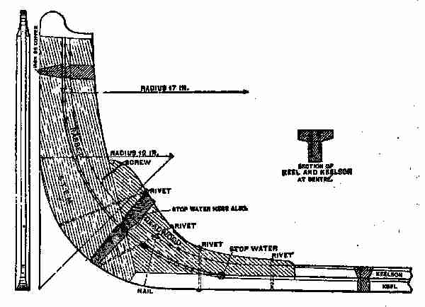
Fig. 24. Stem of launch
After tea, all walked to the boat house, and the father assisted Fred to set up the keel, which was in two pieces, halved together midway and well fastened with screws. The joint was painted with a heavy coat of white lead and linseed oil paint, before being put together and screwed up. The keel is the lowest timber in a boat or ship, and it runs nearly the length of the craft. Sometimes there is a keelson placed on the top of the keel, and the ribs of the boat, or stanchions, are made fast to that timber, as shown in the illustration, (Fig. 24,) in which the gains for the ribs or moulds are made. This portion of the boat was put together temporarily, so Fred had no difficulty in assembling the various pieces. The stem, keel, keelson, and deadwood were all made of oak, and looked strong. The keel and keelson were properly laid and adjusted, and after some explanations by Mr. Gregg the manner of setting up the ribs was thoroughly understood. Fred decided to telephone Walter Scott to come down next day, as it was Saturday, and help him to set up the skeleton.
As the weather was getting warm, the whole family spent the evening on the veranda and George introduced the question of naming the boat. He suggested Red Bird, but this did not seem to take well, and several others were proposed but none seemed to suit everybody. Jessie sat quietly on the steps till asked by Fred what her choice would be.
"I would like it called after mamma, Caroline."
"That's a good idea, Jessie," said her father, "and if the boys or your mother don't object, I think we'll settle on Caroline."
Early next morning the boys were out watching for The Mocking-Bird, which very soon made its appearance. Fred and Walter tied the boat up to the new dock and went into the boat house, where the latter began to examine the boat stuff, and to explain the manner of setting it up and fastening it in place.
Nick, who was on hand to help, did the heavy work, and helped to put up the stanchions. Walter seemed quite familiar with the work, and he and Fred soon had the boat so well in hand that it seemed to grow under their fingers. The ribs were easily selected, as they were tied together in pairs and numbered. They were then set in their places according to their numbers and were fastened to the keelson with the strong copper nails. All the nails required for the boat were of copper, because that metal is less likely to corrode than iron or steel.
It was found necessary to brace the ribs in order to keep them in line. Thin pieces of lath were tacked on the tops to hold the ribs the proper distance apart, and longer and stronger strips of wood were used for bracing the boat sideways. These were nailed to the joints in the ceiling or high up on the walls of the boat house.
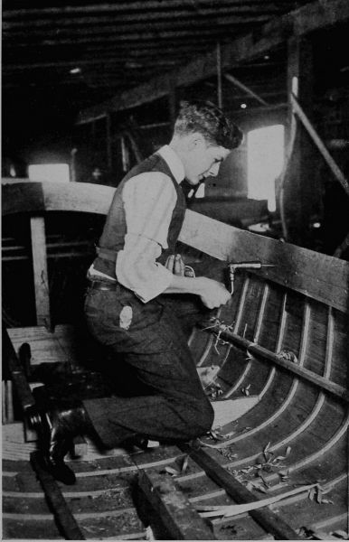
Copyright, 1911, by Underwood & Underwood, N. Y.
Making a Motor Launch "All the Nails Required for the Boat Were of Copper, Because That Metal is Less Likely to Corrode Than Iron or Steel"
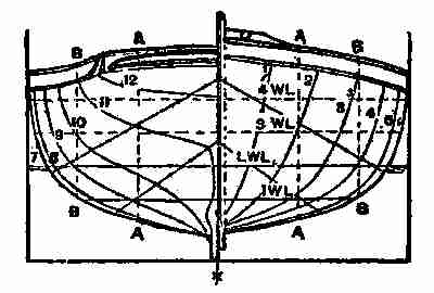
Fig. 25. Section of launch—abeam
At noon the boys had the skeleton of the boat well advanced, and to one standing in front of the bow, it presented an appearance like the sketch shown at Fig. 25.
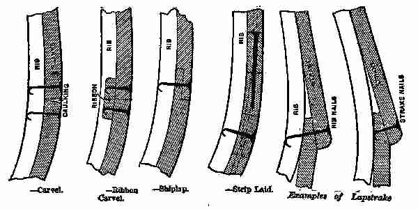
Fig. 26. Methods of sheathing
The launch might be called "carvel ribbon built," or nearly so, and it would have a displacement of 14 or 15 hundred-weight when fairly loaded. This weight would bring her down to the third W. L., as shown in the end sketch. To load her to the fourth W. L., would give her a load far beyond these figures. The sections had to be closely spaced, and the ribbons or slats let into the temporary section moulds before the outside boarding could be put on, the edges of the boarding being clinch fastened, as shown in the ribbon carvel, Fig. 26. Other styles of sheathing boats, as shown, are often used, but the Caroline was "ribbon carvel."
It is usual to lay off the sheer profile on a suitable floor, and line in the rebate line, scarf of stem, deadwoods, fork timbers, etc., making thin moulds of each member to be lined off, sawn, and bolted together. The section moulds, from which the boat derives its shape, are also laid off, and the planking, 3⁄8-in. thick, deducted when making them.
The stem, of crooked oak, was 21⁄4 in. thick by about 3 in., shaped as shown in Fig. 24. The fore deadwood was 21⁄2 in. thick, moulded about 3 in., and through-bolted to the stem and keel with 3⁄8-in. copper bolts; and the stern-post, 31⁄2 in. thick, was wrought to shape, as shown. The centre line of the shaft, as shown, is subject to alteration, since different makes of motors have different sizes of propellers and flywheels. The fork timbers were let into the stern-post, and carried the transom, wrought out of a flitch of elm 31⁄2 in. thick. The planking, of 3⁄8-in. cedar, was closely jointed and varnished, and secured to the ribbons. The timbers were of rock elm, 7⁄8 in. by 1⁄2 in., steamed and bent or sawn to shape, and through-fastened at the top and bottom edges of the planking. These were spaced on 71⁄2-in. centres, with two clinch nails into the ribbons between them. Three or four solid floorings should be worked into the motor space; fitting of the motor bed thwartships gives great support to the boat.
The thwarts were of oak, 8 in. wide and 1 in. thick, with the side seats, 7⁄8 in. thick, supported by turned legs of oak. The decks at each end should be of 1⁄2-in. oak or cherry reeded into 3 in. widths, and filled with marine glue. The covering board, 21⁄2 in. wide, with a nosing worked on the edges, and 1⁄2 in. thick, was carried by a clamp or binding stake, 21⁄2 in. by 5⁄8 in., through-fastened at every timber. The knees were of oak, 1 in. thick, about 10 in. on the foot by about 3 in. at the head, and through-fastened. A breast hook 2 in. thick should be fitted. The floor boards may be of 3⁄4-in. spruce, elm, or ash grating, as preferred. The centre of the motor was at No. 6 section, as indicated, the gasolene being stored in a strong tank under the forward deck, just high enough to feed by gravitation. After being cleaned off and sandpapered, a coat of good shellac varnish, may be followed, if desired, by three coats of best yacht varnish. The spacing of the sections was: No. 1, from face to stem, 1 foot 2 in.; No. 2, from No. 1, is 1 ft. 2 in., the other sections to No. 11 each 1 ft. 6 in.; No. 12 was 1 ft. 1 in. from No. 11 (see Fig. 25). The water-lines were 5 in. apart, and the buttock-lines, A and B, 1 ft. and 1 ft. 9 in. respectively from the middle line.
The boys followed these directions, and with the help of the following table, managed to get the boat ready to varnish and finish up. The following table, which refers more particularly to the section shown in Fig. 25, shows the sheer lines, counting from L W L (low water line). While all the work and calculations regarding the plan had been already done, Mr. Gregg, who had watched the work's progress for a week, thought they should know the principles on which the craft was being built, and therefore advised them to examine the illustration and table, so that they would have some knowledge of the science required to build a boat intelligently. Fred and George did this, and were helped along by Walter, who seemed to have mastered the subject pretty thoroughly.
TABLE OF OFFSETS
StemSection Numbers
12 34
ft.in.ft.in.ft.in. ft.in.ft.in.
Sheer heights above L.W.L. 17 16 15 141⁄8131⁄4
L.W.L. to rebate line 7 83⁄4 9 91⁄4
Half-breadths at gunwale 81⁄4 1 31⁄8 1 91⁄2 2 11⁄8
Half-breadths at 4 W.L. 67⁄8111⁄2 18 201⁄2
Half-breadths at 3 W.L. 57⁄8115⁄8 163⁄8111
Half-breadths at L.W.L. 43⁄893⁄8 135⁄8183⁄4
Half-breadths at 1 W.L. 21⁄253⁄4 101⁄213
Buttock A from L.W.L. 51⁄2 41⁄863⁄8
Buttock B from L.W.L. 3⁄8
TABLE OF OFFSETS. Continued
Section Numbers
567 89
ft.in.ft.in.ft.in. ft.in.ft.in.
Sheer heights above L.W.L.123⁄4121⁄4 121⁄8121⁄8121⁄2
L.W.L. to rebate line 91⁄297⁄8 10 101⁄2103⁄4
Half-breadths at gunwale 231⁄2241⁄2 243⁄8235⁄8221⁄8
Half-breadths at 4 W.L. 227⁄824 237⁄8231⁄4213⁄4
Half-breadths at 3 W.L. 22 231⁄4 231⁄4221⁄2203⁄4
Half-breadths at L.W.L. 20 211⁄2 211⁄2205⁄8191⁄2
Half-breadths at 1 W.L. 163⁄4181⁄2 181⁄2161⁄2107⁄8
Buttock A from L.W.L. 75⁄88 8 71⁄251⁄4
Buttock B from L.W.L. 33⁄843⁄4 43⁄431⁄23⁄8
TABLE OF OFFSETS. Continued
Section NumbersEnd of Transome
101112
ft.in.ft.in. ft.in.ft.in.
Sheer heights above L.W.L.13 1 35⁄8 141⁄416
L.W.L. to rebate line 11
Half-breadths at gunwale 20 191⁄2 163⁄4
Half-breadths at 4 W.L. 1113⁄8171⁄4
Half-breadths at 3 W.L. 191⁄481⁄2
Half-breadths at L.W.L. 121⁄8
Half-breadths at 1 W.L. 53⁄4
Buttock A from L.W.L. 1 6 113⁄4
Buttock B from L.W.L.
It was necessary, before installing the motor, that a foundation should be laid for it, so varnishing and the final finish were left over until the engine and propeller should be put in and tried.
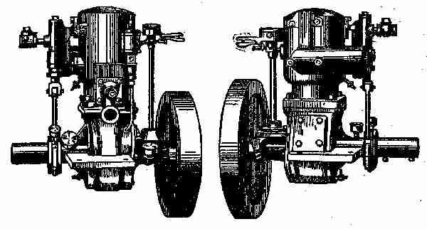
Fig. 27. Starboard side of motor Fig. 28. Port side of motor
The engine was brought to the boat house from Newark, and the expert, engaged by Mr. Gregg some time previous, came along with it, bringing such tools as he might want. He examined the bed for the engine, and saw that all was properly fastened and in good condition to place the engine and the propeller shaft. Mr. Watts (the machinist) laid off a line for the propeller shaft and with a long auger bored a hole from the engine bed through to the stern-post, large enough to permit the shaft of the propeller to revolve in it easily. A bearing, or "box," was adjusted to the stern-post in which the shaft ran, and the "box" was made water-tight to prevent any inflow. The propeller was made of bronze, had been nicely fitted to the shaft before it came, and had a set screw in its hub to hold it firmly on the shaft. The diameter of the propeller wheel measured 15 inches and it had two blades. The shaft and wheel being properly adjusted, the next thing was to place the engine, which weighed about 200 lbs. The blocks and tackle used in taking down the old barn were rigged up to the ceiling by cutting a hole through the floor, laying a short timber across the joists, hitching a rope around the timber, and letting a loop hang down through the hole made in the floor. The hook of the upper block was attached to the loop, a sling was fastened to the engine, the whole was hoisted by Nick with the greatest ease, and the machine dropped on its bed. As it did not lie quite level, it was raised again and held suspended until the bed was trued up, when it was permanently lowered into place and fastened down. Two views of the engine are shown in Figs. 27 and 28.
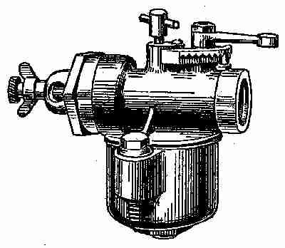
Fig. 29. Carburetor
In "shop talk," the engine may be described as follows—Bore of cylinder 41⁄2 in. Stroke 41⁄2 in. Crank shaft 13⁄8 in. Revolutions per minute from 60 to 750. Propeller shaft one inch. About 15 or 16 horse-power. A float-feed carburetor, Fig. 29, was installed at the same time. This carburetor is an excellent one. It insures a regular supply of gasolene and air, in proper proportion, and prevents trouble when the motor is in use. The float guarantees an even level of gasolene in the float chamber at all times. The proper balance of the cork float closes the supply of gasolene automatically when it reaches the proper level. This prevents waste of fuel, every drop being thoroughly vaporized and mixed with the proper amount of air. The spraying nozzle is higher than the gasolene in the float chamber, and prevents the gasolene from getting into the engine, unless it is running. The throttle valve on the carburetor gives the operator the power to change instantly the speed, without changing the timer, and affords him absolute control of the engine.
When all the machinery was in place, and the propeller attached, Mr. Watts told the boys that he would finish up the work of installing the next day, and would then run the engine "dry" for an hour or two, to get everything working nicely before declaring the Caroline ready for sea.
It was just two weeks from the day the stuff arrived when the engine was finally installed.
"That's pretty quick work," declared Walter, "and if the boat were varnished, we could have her in the water in a couple of days."
In the evening, as all the Greggs were seated on the veranda, Fred tried to explain to his father the installation of the engine, but he failed to make himself quite clear.
Mr. Gregg said to him: "You seem to have grasped the theory of the matter, but I see you don't understand some important points, so I think a few suggestions may be of use to you. I will not confine myself to marine motors altogether, as gasolene engines are used for many purposes, more and more every day. With regard to installing an engine in a boat, the first question is the bed, as you have seen in your own case, where your foundation is made good and solid.
"Small engines may be supported upon a single cross piece at each end of the bed, but this method should be employed only for the smallest sizes.
"The heaviest, and in most cases the hardest, pipe to fit up is the exhaust. It runs from the exhaust nozzle on the engine to the muffler and thence outboard.
"The muffler is commonly placed in the stern with the outlet directly outboard. It may, however, be in any convenient position, like under the seats in the standing room, and the piping led outboard. In any case, the piping for the exhaust should be as direct and as free from sharp bends as possible.
"When the motor is near the middle of the boat, a good practice is to lead the exhaust pipe out through the bottom, and along it to a point near the stern, where it again enters the boat and connects with the muffler. The outlet from the muffler then leads directly outboard as before. This method, especially on a large cabin boat, avoids much loss of space and the disagreeable heat of the exhaust pipe. The surrounding water quickly cools the exhaust, reduces the pressure and makes the exhaust almost noiseless.
"The particular function of the muffler is to afford a comparatively large space into which the exhaust may pass and expand, greatly reducing the pressure. The gas, under the reduced pressure, then passes out with little disturbance. The muffler need be of no particular shape, as long as the volume is sufficient. It is usually made of cast iron in the smaller sizes and of sheet iron in the larger. In many cases a long piece of rather large pipe will answer the same purpose.
"The muffler may be dispensed with and much space saved by carrying the exhaust directly through the bottom of the boat and exhausting under water. Although this is a very convenient and many times satisfactory way, great care must be used or poor results will be obtained. When the exhaust leads directly out, a certain amount of pressure is used in displacing the water. This pressure is, of course, supplied by the piston and is a 'back pressure,' retarding the piston and decreasing its power.
"A small expansion chamber or muffler should be provided between the engine and the outlet, in order to break up the violent pulsations and make the flow fairly constant. Some form of shield should be fitted over the outer end of the exhaust pipe to guide the stream of the exhaust aft and prevent the water being forced into it by the movement of the boat. Several forms of these are on the market in the shape of brass castings which bolt on to the outside of the hull and have a thread on the inside to take the exhaust pipe.
"When the under water exhaust is fitted, a pet cock should be put in the exhaust pipe near the engine. This is opened when the engine is stopped, thus preventing the water from being drawn up into the cylinders by the vacuum caused by the cooling of the gases in the pipe and cylinders.
"The under water exhaust is a very neat and simple method, when correctly installed, as all noise and heat from the exhaust pipe are avoided. The exhaust may be considerably cooled and the noise reduced by dispersion.
"With regard to stationary engines, used for domestic or other purposes, any old place is considered good enough to put them in. Now, this is one of the biggest and most expensive mistakes one can make, for as soon as some small screw gets loose in the far corner, the engine, salesman and manufacturer are unjustly blamed, simply because the present owner has not left enough room to make the small adjustments necessary in every engine and piece of machinery. Therefore, it pays always to install the engine in a light, dry place, easy of access and with sufficient space all round to enable all parts to be reached and to give plenty of room for turning the fly wheels in starting. Whenever possible, place the engine on the ground floor. On an upper floor, the necessary provision should be made to avoid vibration; if installed in the basement, place it in the best light.
"Without a good foundation, an engine may be expected to give more or less trouble from vibration, since it is subjected to forces, suddenly and repeatedly exerted, which produce violent reactions. Care should be taken to excavate down to good soil and to line the bottom with a substantial thickness of concrete in order to form a single mass of artificial stone. The foundations may then be built up of either concrete, brick, or stone. Anchor plates should be extended to the bottom of the masonry and fastened so as to prevent turning while the nuts are being screwed up. Place gas pipes or tubes with an inside diameter twice the diameter of the bolts around them, while the foundation is being built; this allows the bolts to be adjusted, and any variations between the tubes may be filled with thin cement after the engine is set.
"The top of the foundation should be finished perfectly flat and level with a dressing of cement, and after this is thoroughly dry the engine may be placed in position. When bolting down the engine, it is better to draw each bolt down a little at a time until all are tight and thus avoid straining the engine crank. After the nuts are drawn tight, if the crank turns unreasonably hard without loosening the main bearing caps, it may indicate an uneven foundation, which is a strain in the engine bed casting.
"When setting up large engines, for farm or other purposes, especial care must be taken to avoid straining the bed castings. Foundations hung from an upper floor, or built upon it, should be placed as close to the wall as possible. For the smaller sizes of engines it is a good plan to lay wooden beams on top of the foundations and then to place the engine on top of them so that when the frame is bolted down it beds itself into the timber. The timber cap often saves an annoying vibration when it can be overcome in no other way.
"All the connections should be as short and as free from turns as possible, and no mistake can be made by having plenty of unions, so as to disconnect with ease. The gasolene tank should be set as near the engine as is convenient, with the top of the tank, preferably, not more than a foot or two below the base of the engine. In cases where the gasolene tank must be set from forty to fifty feet away, it is necessary to place a check valve in the suction pipe near the tank. Both suction and overflow pipes must have a gradual rise all the way from the tank to the pump and should be as straight as possible to avoid the air traps, which prevent a steady flow of gasolene. It is most essential to clean thoroughly all pipes and fittings before they are put together, by hammering lightly to loosen any scale and washing out with gasolene, as solid matter of this nature may be responsible for some of the simple, but hard-to-get-at troubles common to gasolene engines.
"Shellac is best for joints in gasolene piping, but when this cannot be obtained common laundry soap will answer the purpose just about as well. Remember, also, that gasolene is a rubber solvent, and should never be applied to joints where rubber is used. In some cases it will be found advisable to use gravity feed instead of a pump, except in the case of the tank, which must be so arranged that its lowest point is slightly above the generator valve.
"The exhaust pipe must be of full size, free from turns and short as possible, since the shorter it is the more economically the engine will run. It will be found advisable to place the muffler and exhaust piping away from combustible material, and never to turn the exhaust into any chimney or flue.
"There are two general methods of supplying the water, the first being that of the cooling tank commonly used with small engines. For convenience in piping, the tank should be slightly elevated, and both pipes, having as few bends as possible, should slope from the tank to the engine, a valve being placed in the bottom pipe near the tank. By using a circulating pump, fitted to the engine or shaft, water may be used from an underground cistern or tank.
"The other method is to use a continuous cooling stream from water-works or other source. When city water is used, it is a good plan to have a break and funnel inserted in the drain pipe so that the current of water flowing through the cylinder jacket may be seen. For making joints in water pipes, either thick lead or graphite may be used with almost equal success. It may be well to place particular emphasis on the fact that it will pay to get into the habit of always shutting off the water at the tank and draining the cylinder every time the engine is stopped—not necessary in summer, but absolutely essential in winter—as a fair percentage of gasolene users know to their cost.
"The greatest care must be employed in using and handling gasolene, as it is dangerous and highly explosive. It has been known to explode when 20 or 30 feet from light, the vapours having reached the fire in the way of a gas, igniting and firing the liquid. And, now, right here, let me impress on you this warning; never handle gasolene near a fire or light under any circumstances, and be very careful with it under all conditions.
"Fortunately, there are few accidents resulting from gasolene, when we consider the large amount used since it has become almost a universal fuel for engines, and it is also used largely for domestic heating and lighting.
"It is a product of petroleum, of which in its crude form about 76 per cent. is turned into kerosene, 11 per cent. into gasolene, 3 per cent. into lubricating oils, and the balance into vaselines, paraffine, coke and so forth.
"Different petroleums produce different proportions of the various products, some of them being considerably richer in gasolene than 11 per cent.
"Gasolene is usually designated according to its specific gravity by an arbitrary measure, known as Baume's hydrometer scale. This designation is in degrees, the most common gasolene ranging between 65 degrees and 85 degrees, and the average being 70 degrees, the usual density used in engines.
"You will find it somewhat difficult at first to start up your engine when you wish to, so I will give you a few hints to show how this difficulty may often be overcome.
"There is always a reason why a gas engine refuses to obey the behest of its driver.
"In the first place, see that the compression is right and the admission valve so tight that it will admit only enough of the mixture (gasolene and air) to make a charge that will take fire from the sparker and move the piston forward. Next see that the sparker is clean, that it will make a bright spark at white heat when the contact is broken, and at the right time. 'In time' means to go if everything else is right, and 'out of time' means not to go even when everything else is right.
"The valve of the engine must be kept well ground down with emery and oil so as to preclude the possibility of a leak, as one would very seriously weaken the power of the engine even after it had started. The spark must be made when the connecting rod of the engine is on the 'up stroke,' with the crank shaft about three inches below the horizontal line of the centre of the index, and herein lies the whole secret of the greatest efficiency from the least amount of gasolene. As there is an interval of time after the spark is made until it ignites the charge, it is very evident that the movement of the machinery continues and the moment of ignition should take place when the compression is greatest. This will be when the piston is on its farthest 'in stroke,' i. e., in perfect line with the centre of the cylinder. But if the charge be ignited at this point the engine will not develop the greatest power, as the interval spoken of will elapse and the piston will have started on its 'out stroke', thereby not getting its full force of the expansive gases liberated by combustion of the air and gasolene.
"So you will readily see that you must allow for the interval spoken of, if you would get full returns for the energy used in propelling the motor. I have tried to make this plain, and I hope my efforts will help you out with your engine, either in starting or developing the power at which it is rated."
It was not yet late, so the boys took down from the book shelf a code of yacht flag signals, and found the following:
"There are no hard and fast rules regarding shapes and colours of yacht bunting, but the following are generally accepted by the prominent clubs in the United States and in foreign countries.
1. The "pennant" (a triangular shaped flag) is used for the club burgee.
2. The "shallow tail" is adopted for the private signal.
3. The rectangular flag is chiefly used for a flag officer's signal.
4. The shape, consequently, at once denotes whether a flag is that of a club, a flag officer, or a member.
5. The majority of flag officers' signals are coloured: Blue for commodore, red for vice-commodore, and white for rear-commodore.
6. The international code of signals enables yachts to communicate with each other, and is also used for dressing ship.
The ensign should be flown from the peak of the main-sail on a sailing yacht, when under way, and from a stern flag pole when moored.
On a yawl, it should be hoisted at the mizzen truck.
On a steamer, launch, or dinghy, it should be flown from a stern flag pole, when under way or at anchor.
Club Burgee.—The burgee should measure in length about one-half inch for each foot of height of truck from the water; width to be two-thirds of the length. Private signals may be smaller.
The burgee should be flown from the mast-head or truck of a cutter, sloop, or cat-rigged yacht, the main truck of a yawl, the fore truck of a schooner and steamer, and from the bow pole of a launch or dinghy.
Flag officers' and private signals should be flown from the truck of a cutter, sloop, or cat-rigged yacht, the main truck of a schooner, yawl, or steamer, and from the bow pole of a launch or dinghy.
The following flags are not considered as colours:
Night Pennant (blue).—Is hoisted at the main truck from sundown to 8 A. M.; also occasionally used as a tell-tale when racing or sailing.
Owner's Absent Flag (blue rectangular).—Is flown from the main starboard spreader when yacht is at anchor only. It denotes owner is not on board, but should never be flown when under way.
Owner's Meal Flag (white rectangular).—Is flown from the main starboard spreader, and denotes the owner is at meals—boarding a yacht when this flag is flying is considered bad form.
Crew Meal Flag (red triangular).—Is flown from the foreport spreader on schooners and main-port spreader on single-masted yachts. This denotes that the crew is at meals.
The Ensign.—Displayed on a vessel indicates distress and want of assistance.
Flag "B," of the International Code of Signals, is used for a protest flag, and is conspicuously displayed in the rigging of a yacht protesting during a race.
A yacht, on withdrawing from any race, should at once lower its racing colours, and allow yachts still competing the right of way.
This code was studied by the boys until both of them thoroughly understood its full meaning, and George became so enthusiastic over it that he exclaimed: "Fred, I am going to be an admiral of the navy!"
V A TALK ABOUT ENGINES
Mr. Watts was early at the Gregg residence next day, and busied himself preparing the engine to start up. A big tub was taken to the boat house filled with water by a hose attached to the suction pipe, and dropped into the water. This was a mystery to George, who inquired about the use of the water and the other attachments. It was explained to him, that outside the cylinder there was a hollow space, called the "water jacket," extending over the top of the cylinder, and this had to be kept full of cold water by continual circulation. It was pumped in by the engine and forced out by the same means, a simple contrivance being arranged for the purpose. This circulation of water is necessary to keep the inside of the cylinder cool, otherwise the walls would soon become red hot, on account of the rapid explosions of gas and air employed in the cylinder to keep the piston moving to and fro.
George seemed to grasp the idea thoroughly. Mr. Watts also explained the use of the carburetor, the spark coil, the battery, and the method of contact to produce a spark at the proper moment. After some screwing of bolts, adjusting the piston, and trying the valves, the tank in the carburetor was supplied with gasolene and Mr. Watts tried the engine for a few revolutions, as gently as it could be done. It was a little stiff at first, some of the connections fitting too tight, and the piston, being new and harsh, did not work smoothly. By the judicious use of good lubricating oil and a few turns of some of the nuts on the bolts, a little more freedom was given to the machine and the starting was easy and smooth. George and Jessie were delighted with the rapid movement of the machine, the buzz of the propeller, and particularly interested in the movement of the water in the tub.
Mr. Watts allowed the engine to run quite a little while, and arranged the exhaust so as to beat regularly and to "pop! pop!" as little as possible. He then called Fred into the boat and taught him how to run the machine, arrange the contact breaker, and regulate the feeding of fuel. The engine was stopped to cool and to be examined again by Mr. Watts, who pronounced it all right. Mr. Gregg, who had arrived just before the engine was stopped, examined all its parts and watched it work for a minute or so.
Fred arranged his pots and brushes, and he and George went to work varnishing, so that before sunset the Caroline looked quite smart and trim. The boys were very careful in applying the varnish to put it on light and thin so as not to let the coats lap over one another as they went along. They finished each "streak" from end to end, before starting on the next, and following this method they obtained a nice, even surface. The varnish did not look "blotchy" or patched, as it would have done had the ends of the varnish lapped. To avoid "lapping" is one of the most essential operations in varnishing, when a nice piece of work is desired.
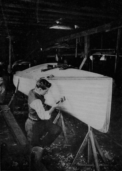
Copyright, 1911, by Underwood & Underwood, N. Y.
Finishing the Motor Launch "To Avoid 'Lapping' is One of the Most Essential Operations in Varnishing"
It was decided to give the little craft two more coats of shellac varnish before launching her, and the following spring to give her a good coat of marine varnish. Mr. Gregg thought that in another week, say the following Wednesday, the Caroline might be launched with safety, as the varnish would get dry and hard, and the inside paint would also be hard enough. Jessie and the boys were given permission to invite a few friends each to the boat launching, and were promised suitable refreshments to be served on the new grounds, if the weather was favourable. Fred asked his father if he could not build up some temporary picnic tables and seats for the occasion, as there was plenty of material still left unused from the old barn stuff. Permission was granted, and after counting up the number that would probably be present, it was found that three tables, each about fifteen feet long, with necessary seats, would give ample room for the accommodation of the proposed guests, with a good allowance for overflow.
Just then the whistle of a small steam tug, that often plied on the river, gave warning of her approach; and all went down to the river edge to watch her pass and to see what effect her "wash" would have on the new pier and the boat house "skid" or slides. She came up stream rapidly against the tide—which was on the ebb—and there was a considerable "wash" from her wheel, but it struck the bank, the pier, and the "skids" without doing the least harm or giving any evidence that trouble would result from any reasonable wash. The little steamer's exhaust, as she passed, made quite a noise and Jessie was somewhat puzzled at this, as the exhaust from the gas engine of the Caroline only made a plaintive puff in comparison. Her father promised to explain the reason after tea.
Returning to the boat house, George suggested that the name of the boat be painted on both sides of the bow, in large letters, but Mr. Gregg and Fred, thought it better to have "Caroline" placed on the second streaks of sheathing, in gold, the letters to be not more than two inches over all. This was agreed upon, and a young artist, who was a near neighbour, was suggested as the person to do the work.
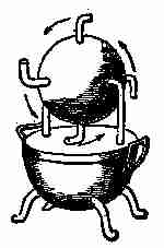
Fig. 30. Hero's steam engine
After tea, Jessie and the boys followed their father into the den, where Mr. Gregg gave the children a brief history of the steam engine, as far back as known, commencing with the Colipyle, the invention of Hero of Alexandria about 130 B.C. An illustration of this is shown in Fig. 30. It was simply a pot or boiler, partly filled with water, the lid or cover being fastened down tightly. On the top of this was attached a hollow bent tube having a tap fitted to it, which supported and communicated with a hollow metal ball hung on another tube or bearing on the other side in such a manner that the ball could revolve easily. Attached to this hollow ball or sphere were four other hollow tubes, so fastened as to project from the surface two or three inches, and these were bent at their outer end, as shown in the illustration. These tubes were of course attached and bent in a direction at right angles to the axis of rotation. The tap leading to the hollow ball, when turned open, allowed the steam from the boiler to rush into the ball and fill it up. If it was closed entirely, the ball would remain still, but the steam exerting an equal pressure on all points of the inner surface, and finding the openings, escaped through with a rush and noise as it condensed in the air, which it pressed against, causing the ball to revolve in an opposite direction to the outflow of steam. This Hero engine or Colipyle, was doubtless the beginning of steam motors, but during the 2,000 or more years since Hero's toy engine was invented, great strides have been made toward bringing the steam engine to its present efficiency.
"But I do not intend," said Mr. Gregg, "to give a history of the growth and development of the machine, at this time. There are numerous works on the subject, obtainable in any fairly-equipped library."
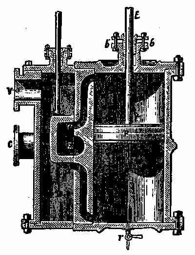
Fig. 31. Steam cylinder and piston
Steam, as everybody knows, is generated by heat being applied to a closed metal kettle or boiler containing water. This boiler must be strong and properly arranged so as to admit more water—which is usually injected with a force pump—and it must have an outlet for the release of the steam to the cylinder of the engine. Generally, there is a small dome on the top of the boiler, called the "steam dome," and to this the steam outflow pipe is attached. The actual use of this dome is to hold a volume of steam that will remain unmixed with water, as it is placed considerably above water level. On the top of the dome there is an automatic arrangement called a "safety valve," so that when there is too much pressure of steam in the boiler, it will open and allow the over-pressure to escape, and thus prevent the boiler from exploding or being over strained. This valve is controlled by a simple device, somewhat similar to a steelyard. A movable weight is arranged to slide on a long arm which is loosely fixed to the valve flange by a bolt and nut, and extends some distance past the seat of the valve. The arm or lever has an iron pin attached to it directly over the valve seat, which holds down the valve and keeps the steam from escaping. The movable weight on the arm is adjusted so as to regulate the pressure on the valve. When there is too great a pressure, the valve forces up the lever, and at the same time opens a passage for the extra pressure of steam to escape. There are several other contrivances for relieving the boiler of over stress, but the one described, or rather the principle on which it is built, is most in use on this country. There are many kinds of boilers, or steam generators, but the best, and very likely the strongest, are those employed on our first-class railway locomotives. These are frequently under a pressure of 200 or more pounds to the square inch, which seems an enormous load for a hollow shell to carry, yet, so near perfection are they, we rarely hear of a locomotive boiler explosion. As there are many kinds of boilers, so also are there many kinds of steam engines, but all of these latter, with very few exceptions, have a cylinder and piston for converting the force of the steam into useful and effective motion. The manner of using this force and keeping it under proper control is somewhat complex and difficult to describe briefly, without elaborate diagrams, but Mr. Gregg explained, in his own way, how the great force was converted into motion. On the blackboard he drew a rough diagram of a cylinder and valve or steam-chest, with piston and slide-valve, about as shown in Fig. 31, which gives a longitudinal section of the whole arrangement. Here we see near each end, the opening of a double conduit aa, made in the thickness of the side; these are the openings by which the steam comes alternately to work on one end, then on the other, of the piston. These are called the steam-ports. These two open outward on a well-polished surface, and between the two a third opening, E, is seen, which serves to let the steam escape when it has done its work, and is called for that reason the exhaust port. C is the pipe by which the steam gains access to the open air or to the condenser, where it parts with its elastic force.
Here is shown by what contrivance the distribution is effected, consisting, as it does, of two partial operations; the admission of the steam and its escape, which must be repeated twice to obtain a complete phase of the to-and-fro movement of the slide-valve. There are various methods employed according to different engines—but the first described is the one represented by the illustration.
In the valve chest, BB, is seen a prismatic box, open on one side, called the slide-valve, and this is applied by its open face to the well-polished plane on which, as mentioned before, the three ports open. The space BB, is called the valve or steam chest. The steam coming from the boiler by the pipe C spreads out freely in it, but the inside of the slide-valve, on the contrary, is always closed to the entering steam, though constantly in communication with the escape pipe and also with first one then the other of the entrances to the cylinder. Lastly, the movement of the slide-valve is produced by the engine itself, aided by a rod and an eccentric fixed to the shaft of the fly-wheel.
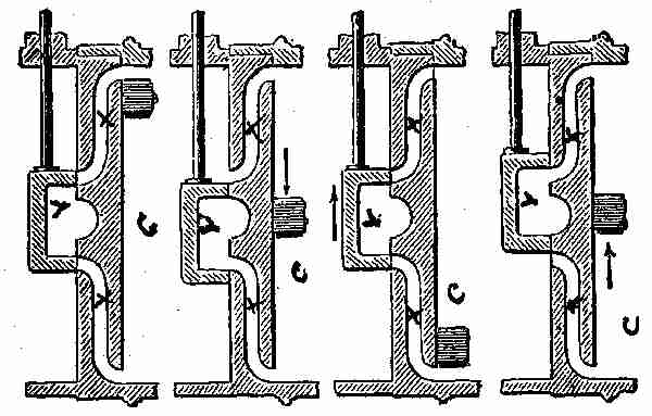
Fig. 32. Steam valves—different positions
By following the successive and alternating motions of the slide-valve, as represented in Fig. 32, we can easily comprehend the different phases of the distribution of the steam.
This is the machinery for the distribution of steam generally. There are other engines, such as rotary and oscillating, that are supplied by other contrivances, but most of these have fallen, or are fast falling into disuse, as they are not so satisfactory as the ordinary slide-valve. It will be seen upon examination of the sketch, shown in Fig. 32, how the steam enters and leaves the cylinder and the position of the piston under the various positions of the valves. The arrows show the direction of the slide, also the direction of the piston and its position when the slide covers the ports X, or leaves them open, or partly so. The ports for egress or ingress are shown at X, the slide-valve at V, and the cylinder at C. When the piston is near one end of the cylinder, the steam is admitted and forces the piston in the opposite direction, while the valve is so arranged that when the piston starts in that other direction, it begins to open the port at the other end of the cylinder through which the exhausted steam escapes. This makes the noise Jessie asked her father about. There are some engines so devised that the exhaust is made to assist in driving another engine.
Of course, there are many kinds of steam engines, but all are run on the same principle, or nearly so. As you know, steam is generated in boilers by fire being applied to the outside and the water made hot enough to raise steam. A steam engine is said to be externally heated, while gas, oil, and other similar engines are internally heated, because instead of the steam driving the piston, the gas, oil, or other explosive matter is admitted into the clearance or space between the piston and the end of the cylinder, where it is exploded by an electric spark from a battery provided for the purpose, and this is called the "ignition." The explosion causes the gas and air in the cylinder to expand, bringing a great pressure on the piston, forcing it to move toward the other end of the cylinder, and making the whole machine move. One great advantage of employing a gas engine is that no boiler is required, a very important matter, as boilers take up a great deal of space. The coal or wood necessary to keep up steam also takes space that could be used for other purposes, all of which make the use of steam objectionable when it is possible to employ suitable gas engines. Besides, the make-up of a steam engine is of such a character that it is very expensive, while the first cost of gas engines is much lower.
All gas, oil, or other explosive engines are internal heaters, because the heat is generated in the cylinder at each explosion, and this is one of the main features that distinguishes the gas from the steam engine. Of course, there are many attachments and connections to steam and gas engines that would take too long to describe, and in a great measure be unnecessary. A few items may prove both useful and profitable and it is well to know firstly: How to estimate the horse-power of an engine.
When steam engines were first introduced they were largely used to take the place of the horses previously employed for raising water from mines. Naturally people inquired, when buying an engine, what amount of work it would perform as compared with horses. The earliest engine builders found themselves very much at a loss to answer this question so they had to ascertain how much a horse could do.
The most powerful draught horses and the best of any then known were the London brewers' horses. These, it was ascertained, were able to travel at the rate of two and a half miles per hour and work eight hours per day. The duty, in this case, was hoisting a load of 150 pounds out of a mine shaft by means of a cable. When a horse moves two and a half miles per hour, he travels 220 feet in a minute, and, of course, at the speed named, the 150-pound load would be raised vertically that distance. That is equal to 300 pounds lifted 110 feet per minute, or, 3,000 pounds lifted 11 feet or 33,000 pounds lifted one foot high in one minute. That is the standard of horse-power, as we all know. It is much more, however, than the average horse can do, and therefore the builders were confident that the engines would take the place of fully as many horses as the horse-power would indicate that they should.
Of course, 33,000 pounds lifted 1 foot per minute is much more convenient for calculation than 150 pounds lifted 220 feet, and therefore the former rate has been adopted. The amount of work, or number of "foot-pounds," is the same in either case. A foot-pound represents the amount of power required to lift one pound one foot high. To find the number of horse-power in any engine, we multiply the area of the piston by the average pressure per square inch upon it; multiply this result by the distance which the piston travels per minute in feet and the result is the number of foot-pounds per minute which the engine can raise. Divide by 33,000 and the result will be the number of horse-power. The number of feet per minute travelled by the piston is twice the number of strokes per minute multiplied by the length of the stroke. This gives the amount of horse-power sufficiently accurate for all practical purposes.
It necessarily takes time to do work, but the amount of work done has nothing whatever to do with the time taken to do it.
If a man, weighing 150 pounds, walks up the 900 steps leading to the highest attainable level in the Washington Monument, 500 feet high, he does work against gravity equal to 75,000 foot-pounds, irrespective of the time taken in the ascent. Then the work done in a given time, divided by the time, is called the power of activity.
Power is the time rate of doing work. In the English gravitational system, the unit of power is the horse-power (H.P.); it is the rate of doing work equal to 33,000 foot-pounds a minute, or 550 foot-pounds a second.
In the centimetre-gramme-second (C.G.S.) system (in which the unit is 1 gramme moving at the rate of 1 cm. a second), the unit of power is the watt. It equals work done at the rate of one joule (10,000,000 ergs) a second.
One horse-power is equivalent to 746 watts.
A kilowatt (K.W.) is 1,000 watts.
It is therefore nearly 11⁄3 horse-power.
To convert kilowatts into horse-power add one-third; to convert horse-power into kilowatts, subtract one-fourth.
For example, 60 K.W. equals 80 H.P. and 100 H.P. equals 75 K.W.
The expression foot-pound is in general use among English-speaking engineers, and as explained it is the unit of work done by a force of one pound working through a distance of one foot. It is not a fixed standard of measurement, since the weight of a pound is not the same in all heights above sea level, and on this ground it is open to objection. It is the nearest constant, however, we have yet discovered, hence its general adoption.
"Dry steam" is the steam in which no condensation is visible, and it may generally be obtained at a 10-pound pressure per inch, but no exact dividing line of pressure can be defined between dry steam and wet. If care is taken in covering pipes and cylinders, to prevent condensation, a pressure of 10 pounds should make steam as dry as gas, and if the steam pipe is carried through a good, hot fire at some point, the fire will superheat the steam and render it more dry. Wet steam, of course, is steam that can be seen, through having been more or less condensed by contact with air or cold. There can be no steam without heat, but steam does not require as much heat as is generally supposed. Suppose we take one pound of water at 32 degrees Fahrenheit and apply a fixed and known quantity of heat until it boils; we will assume that it takes 20 minutes, and we have supplied the water 180 heat units, which, added to the 32 contained in the water at the start, makes 212 degrees Fahrenheit or heat units, and is the sensible heat of steam at atmospheric pressure. Now let us continue the same quantity of heat per minute until all the water has evaporated into steam, and we will then find that it has taken five and one-third times as long, or 107 minutes to do this work. Consequently we have used five and one-third times 180 or 960 heat units; or, to be exact, 966 heat units. Now the temperature of the steam is the same as the water from which it has evaporated, or 212 degrees Fahrenheit, and this 966 heat units is the latent heat of steam at atmospheric pressure. All steam has a sensible heat corresponding with the temperature of the water it has evaporated from. If you boil water under a pressure of five atmospheres, or 75 pounds pressure, the sensible heat is 306 degrees Fahrenheit, the boiling point at that pressure, but the latent heat has decreased by the same number of heat units that the boiling point increased, so the total is the same in all cases. In the first instance we have 212 degrees minus 32, plus 966, or 1,146; and in the second 306 degrees minus 32, plus 872 or 1,146 heat units. This may be considered a fair description of latent heat.
The most useful quality of steam yet discovered is its power of expansion. It follows what is known as Marriott's Law of Expanding Gases, which means one-half the pressure double the volume. So if we let steam into an engine cylinder, at 80 pounds' pressure, and cut it off at one-fourth stroke, it is at 80 pounds up to the point of cut-off. At one-half stroke, because it has doubled its volume, it is reduced to one-half pressure, or 40 pounds; while at three-fourths stroke the volume has trebled and the pressure has dropped to nearly 27 pounds, and this is why it is economical to run engines that use steam expansively. Steam at 27 pounds' pressure is very much cooler than steam at 80 pounds, and this difference in temperature has been converted into mechanical work by our steam (heat) engine.
There are many other peculiarities about steam and steam engines that a young boy should know, and the information can readily be obtained from books in any good library.
The steam turbine, of which so much has been heard lately, is not constructed like an ordinary steam engine with cylinder, slide-valve and other attachments; but more like the Hero engine, with this difference that the steam jet or jets act on a wheel having vanes or blades, the expansion producing a velocity which rotates the wheel containing the vanes. A modern turbine, of the Parsons type, such as are employed on the great Atlantic steamers, is a tremendously high speed engine. It does not derive its power from the static force of steam expanding behind a piston, as in a reciprocating engine. In this case the expanding steam produces kinetic energy of the steam particles, which receive a high velocity by virtue of the expansion, and, acting upon the vanes of a wheel, force it around at a high speed of rotation in the same manner as a stream of water rotates a water-wheel. The expansion produces velocity in a jet of steam, and this is the main difference between the ordinary engine and the modern steam turbine.
Among gas and internal explosion engines there exist some differences, both in construction and in the manner of supplying fuel. The gas-producing engine may be considered the better class, though it has not as yet gained the popularity of the gasolene one. The gas by which this style of engine is operated is produced by a special process, namely, by passing air and steam through a fire of hot coals. After generation the gas passes over a flash-boiler and a portion of its great heat is withdrawn, thus permitting it to enter a scrubber—a cylinder filled with coke and sawdust—while fairly cool. In passing over the flash-boiler the great heat raises all the steam necessary for the production of gas required in the operation of the engine and plant. In passing through the scrubber the gas is not only cooled, but is freed from particles of suspended matter, the coke removing the heavier particles, and the sawdust, the tar, or any other volatile matter that may be left.
One of the most important requirements in a gas-producer is that it shall be adapted to the work it has to do. Its construction should be compact and simple, so as to permit the easy removal of worn out parts. The feeding device should be such as to secure a uniform distribution of fuel.
The blast should be so introduced as to burn out all the carbon in the ash zone, and yet not produce localized combustion along the walls. The construction should permit the easy removal of ashes, and render the machine safe, while the entire process of gasification should be clean. The radiation loss should be low, and the producer must be made efficient to insure satisfaction.
It should be borne in mind that because of the presence of carbon monoxide, producer gas will always be more or less poisonous. The carbon monoxide has a specific toxic effect on the human system, and when inhaled enters into direct combination with the blood, and brings about very dangerous effects.
As water is always required for cooling purposes when running a gasolene engine, it is well to know about how much will be required. One authority says: "The quantity of water required at the ordinary temperature of 60 degrees F. inlet and 150 degrees outlet, to keep the cylinder of gas engines cool is 4.5 to 5 gallons per indicated horse-power-hour. The jacket pipe should be from 1 to 2 inches diameter for engines up to 20 horse-power, while for larger engines the sizes are generally 2 to 3 inches for the inlet and 2.5 to 3.5 inches for the outlet. Tanks for circulating the water are generally made with a capacity for furnishing 20 to 30 gallons per indicated horse-power. This rule may be taken as about correct, but, if anything, it is rather an over-estimation of quantity necessary."
All the foregoing was made as clear as possible to the listeners by Mr. Gregg before the children went to bed.
Next morning Fred called up his artist friend, and got him to come down to gild the name "Caroline" on the boat before the next coat of varnish should be applied. The artist made an outline of the name while George and Jessie stood by and watched the process with considerable interest. They saw him measure off each letter, outline it with a pencil lightly, and then paint inside the lines with a substance known as "gold size," obtained from any store dealing in painters' supplies. While the size was still sticky the artist applied "gold leaf," which he had brought in a little book along with him. Jessie was surprised to see him cut the gold with a thin pallette knife, having a blunt but smooth edge. She watched him pick up the small pieces of gold with a camel's hair brush, which he rubbed in his own hair now and again whenever it would not pick up the gold. The metal was applied bit by bit over and beyond the lines of the letters, and a light puff of breath forced it down to the size. When one side of the boat was finished, so far as laying on the coat of gold was concerned, Jessie was very much disappointed, as the name seemed merely a smudge. She could not make out the letters, but the artist told her to wait until to-morrow and he would show her how well they could be seen. Next day with a flat camel's hair brush he dusted away the surplus gold, and the letters showed up in good style, much to the gratification of Jessie and George. This part of the work being done, the boys took down their varnish pots, and gave the little craft another coat, to make her quite spruce and gay.
Fred, and Nick, who was still in the employ of Mr. Gregg, laid off a space on the ground for tables and seats to accommodate the young folks who were coming to the launch on the following Wednesday. Nick found a number of old cedar posts, and with a saw cut off 18 pieces about two feet long and as many more twice that length. The first were intended to place the seats on; the second lot were to sustain the tables. The spots for the tables were chosen, measured off, and small stakes driven into the ground to show where the posts were to be placed. Five posts were intended for each table—two at each end, two feet apart, and nine feet apart in the length of the table. The single post was placed in the centre of the table both ways. When the stakes were all in place, Nick made holes deep enough to take in the posts so that their tops measured just two feet and two inches above the level of the ground. The tables were to be two feet and six inches high when finished, as that is the regulation height. It was attained, in this case, as follows—First by the height of the posts from the ground, two feet two inches; then by a plank two inches thick laid across the two posts, making the height two feet four inches, and the table top, two inches thick, laid on these cross planks, which brought it up to the required height. A piece of plank the same thickness was nailed on the centre post across, so that it would support the table top. Planks that had been used in the loft of the old barn did service for the table tops, bearing pieces, and the bench seats. The last were constructed in the same manner as the tables, the short posts being let into the ground—three under each seat—and fourteen inches above ground so that when the plank seat was nailed on top of them, the seats were just sixteen inches, the regulation height of stools, benches, and chairs, though it is sometimes varied to suit conditions. The benches were placed about four inches out from the edge of the table and were found to be "just the thing."
When Nick had planted the first post for the tables and got it the right height, he took that one for his guide and by the aid of a long parallel straight edge which he laid on the guide post and the one he was setting, and also a spirit-level on the straight edge, he managed to get all the posts alike in height and this made the tops of the three tables nice and level. It was quite an achievement to have three large tables and six long seats placed in "picnic style" at so small a cost and with so little effort.
In order to have the tables and seats neat and clean, George turned on the garden hose and gave them a good wash off, and when they were dry again the place was as inviting as a country hotel dining-room. When Mrs. Gregg, Jessie, and Grace Scott had the tables set and garnished for the launch, the lay out was charming, none the less so because it was a little rustic.
Another coat of varnish, the third, was given the boat the day before she was to be launched, and Fred had a strong rope attached to the winch, with a heavy iron hook fastened to the end of it. A stout iron ring was bolted to the stern of the boat and made secure. Mr. Gregg had purchased a number of small flags and "burgees" and had one made with the name "Caroline" in large letters wrought on it, ready to be unfurled when the launch was made, and Walter Scott, his mother and sister Grace, and others had been invited to attend.
A number of temporary swings were fixed up by Nick and Fred to the trees, some for the large folks, others for the smaller ones, and everything was at last ready for the great event, which was to take place the next day at two o'clock.
VI PROPELLER AND OTHER SCREWS
Wednesday morning was light and sunny and the boys were up and dressed somewhat earlier than usual, so, while waiting for breakfast, they took a stroll down to the river, where they found their father looking over the grounds and examining tables, benches, swings, and particularly the foot-bridge; for, as he told Fred, "it was very likely all the guests might be on the bridge at one time and the combined weight would be rather trying if it had not been securely put together." He satisfied himself, however, that the bridge was strong enough to support three times the weight it would be called upon to sustain. Everything else seemed to be sufficiently strong, to apprehend little danger, no matter how much the children romped.
Nick had the grounds nicely raked off; the decayed branches and shrubs he moved, and made everything about the place as clean and as neat as possible. Flags and other decorations were hung or placed about the grounds, on the trees and buildings, but particularly about the tables and the boat house. Newspapers were spread over the tables, linen covers above them, and the whole surroundings took on a most festive appearance.
It was just 11 o'clock when The Mocking-Bird arrived and tied up to the new dock. On board were Mrs. Scott, Grace, and the maid, who came to help, besides several of the invited guests whom Walter had brought down with him. All were welcomed by Fred, Jessie, and George and then the women visitors went to the house to assist Mrs. Gregg.
Mr. Gregg came home from his office earlier than usual and took a half holiday in honour of the occasion. The guests, in little groups, arrived on time, and before the clock struck two Nick had everything prepared for the launch. He and Fred and George had the Caroline nicely placed on the skid, ready to "let go" the winch, and a flag pole was fixed up on the bow of the boat. To this the flag with the name on it was lightly tied, in such a manner that when a string was pulled it would unfurl, and show the name. The string looping up the flag was left long enough to enable Mr. Gregg, standing on the dock, to hold the end in his hand, and by pulling it to loosen the flag as soon as the boat touched the water.
Everything being ready, Walter Scott invited as many of the young people to get into the Mocking-Bird as could crowd on board with comfort, and each was provided with a whistle or a horn, as he ran his boat half way across the river. The children on shore were also given horns and whistles, and all were told to blow as loud as they pleased when the boat touched the water. Mr. Gregg, having Mrs. Gregg and Mrs. Scott standing beside him, gave the word, "Ready!" Nick and Fred answered, "Aye, aye, sir!" and the master of ceremonies called out in a loud voice: "Let her go!"
Nick freed the winch, Fred and George gave a little push, and the Caroline slid down the skids, into the water, without the least hitch. The horns and whistles made a great din, and when the flag was let free to open up and show the name "Caroline" there was another blast of noise by horns and whistles, mingled with voices of the younger people, who cried out with all their might, "Hurrah for the Caroline!"
The launch being over, and everything having gone all right, the young people were called to lunch. They all sat at the tables which were nicely garnished and well supplied, and there was plenty of small talk, and much laughter and jollity. After lunch, Fred, Walter and George boarded the Caroline, supplied her with gasolene, and tried to run her. They found a little difficulty in starting, but after the engine was warmed up a little, she went off beautifully, and answered her tiller in fine style. The boys ran her up and down the river for a while, then tied her to the dock, and Walter and Fred invited all the girls to "Come and have a sail." The boys were promised one when the two boats returned, which they did in the course of half an hour. The swings were put in use, dancing and romping began, and the afternoon was passed in fun and frolic.
In the evening, Mr. Gregg, Jessie, and the boys took a trip, and Mr. Gregg was well pleased with the boat's performance, particularly with the working of the screw. In mentioning this, he awakened the curiosity of George, who reminded his father that he had not yet explained to them about the screw as a mechanical power.
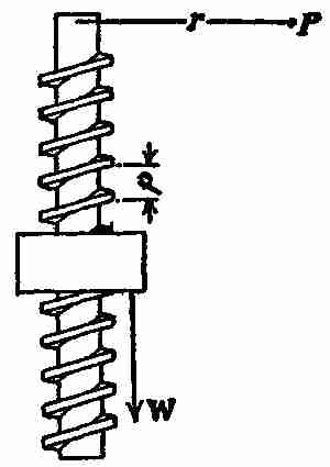
Fig. 33. Theory of screw
That evening George was told to bring his blackboard and equipment into the den, and the father at once began explaining the mechanical qualities of the screw. He told of its great usefulness in the industrial arts. As one of the mechanical powers, it may be considered an inclined plane, wrapped spirally round a solid cylinder. The advantage gained by it depends on the slowness of its forward or backward progress, that is, on the number of turns or threads, as they are called, in a given distance. It is always used in combination with a lever of some sort. When employed as a lifting machine it has great power, and is used to produce compression or to raise or move heavy weights. If a screw is formed on the inside surface of a hollow cylinder, it is called a nut, and used to overcome a resistance; either the screw or the nut may be fixed and the other movable. The acting force is generally applied at the end of a lever or wrench or rim of a wheel. Fig. 33 represents a screw and nut operated by a lever or length of radius r; p is the pitch of the screw or height of the inclined plane for one revolution of the screw. W is the resistance at the nut and P is the force at the end of the lever r. Remembering that, while the resistance W is raised the distance p the force P revolves around a complete circle and moves a distance 2πν. Let us now apply the condition Σwork = 0 and we have
P2πν - Wp = 0 or — = P2πν/p (6).
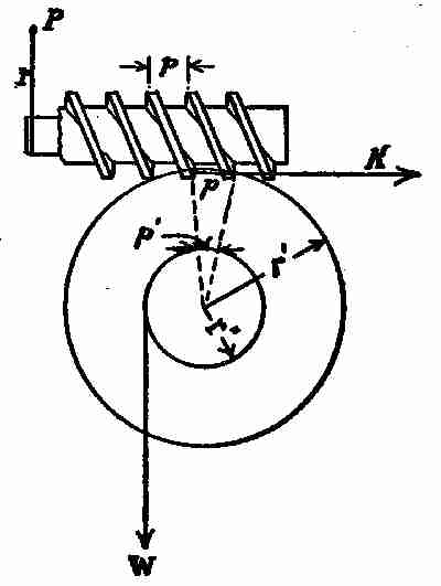
Fig. 34. Worm wheel and screw
The worm gear (Fig. 34) is a special case of screw and nut, where the latter is replaced by a toothed wheel called a worm wheel. The teeth work in with the thread of the screw or worm, and thus, as the worm revolves, the worm wheel revolves about its axis. P is the force acting on the worm at a radius r. r´ is the pitch radius of the teeth in the worm wheel and r´´ is the radius of the drum on which W acts. Let K, corresponding to W in equation W P (6), be the force at the pitch circle and worm threads due to the force P; then K = P2W/p (7).
Now apply Σm = 0 to the worm wheel and we have Kr´´ = Wr´´ or K = wr´´ (8). Substituting the value of K in (7) in equation (8) we have P2πν = Wr´´ or P2πν = Wr´´p (9). Now it is evident that the distance p´ moved by W while K moves through the distance p is to p as r´´ is to r´ or p´ : p :: r´´ : r´ or p´ = pr´´/r´ (10). Substituting this value of pr´´/r´ in equation (9) we have P2πν = Wp´ or the condition Σwork = 0, since 2πν is the distance moved by (P) while W moves the distance p´.
No provision for friction has been made in any of the examples given, so that allowance must be made for this propensity whenever any of the foregoing rules are applied to practice. The amount of allowance required will vary and must be made to suit conditions.
An endless screw is sometimes used as a component part of graduating machines, counting machines, etc. It is also employed in conjunction with a wheel and axle to raise heavy weights. The distance between the threads of the screw is called the pitch or step. These threads are sometimes square, sometimes acutely pointed or edged, sometimes rounded off on the edges. Power is often applied by means of a lever or other contrivance attached to the end of the screw, or by a long handled wrench (a monkey wrench for instance), which, when turned, moves forward in the direction of its axis, overcoming resistance. In the case of the screw-jack, it may be used to raise a heavy weight. The relation between the force applied and the resistance to be overcome is important to note, for every time the screw performs one revolution it moves forward through a distance equal to the space between one thread and the next.
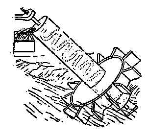
Fig. 35. Archimedian screw
The Archimedian screw we have read and heard so much about is simply a hollow pipe wound around a cylinder. It was often used in olden times for raising water, but is now only occasionally applied. The lower end of the spiral pipe is, of course, left open and immersed in water, as shown in the illustration (Fig. 35), a device for raising water, the supply stream being the motive power. The oblique shaft of the wheel has extending through it a spiral passage, the lower end of which is immersed in water; and the stream, acting upon the wheel at its lower end, produces its revolution, by which the water is conveyed upward continuously through the spiral passage and discharged at the top. An arrangement like this could easily be constructed at the edge of most rivers to raise water to irrigate the grounds, if so desired, and the little flutter wheel at the bottom of the inclined shaft would be powerful enough to lift all the water required. Fred thought that would be a great scheme, and determined to try his hand at it one of these days, but he was told that a wheel of that kind could only work at intervals, as the river's flow was often running in opposite directions owing to the inflow of the tidal water.
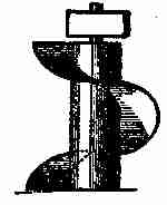
Fig. 36. Spiral conveyor
These Archimedian water raisers are often fitted with a crank handle on top, and a man, standing on a platform, turns the crank and thus lifts up all the water the machine will carry. The Archimedian screw is used for many other purposes than raising water. With wide, thin wings, similar to the construction shown at Fig. 36, and enclosed in a case or jacket, it is employed by millers to convey grain and other mill requirements, and it is also good for moving coal, ore, gravel, and like material, but when used for these coarser purposes the propelling blades are made of steel, riveted or bolted to a strong iron shaft. The case or jacket containing the revolving blades, if horizontal, need not be covered on top, as the blades will propel the material without jamming or clogging, if the jacket is smooth inside, and fits fairly close to the blades.
This style of a screw may be used as a sort of turbine water wheel, if cased in a cylindrical penstock or tube, and a body of water allowed to fall into the upper end of the tube. The force of the water will give a rotary motion to the blades and shaft, and, the latter having a geared wheel or pulley attached to its top, motion is imparted to other shafts and wheels.
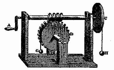
Fig. 37. Theory of screw and gear
Another application of the screw is shown at Fig. 37, where one is arranged on a shaft or axle to give a rotary motion. This device is called a "worm and wheel," and is frequently used in the make-up of machine engines and mathematical instruments. The illustration shows how the power or force of a screw may be conceived. For instance, suppose the wheel C has a screw on its axis working in the teeth of the wheel D, having 48 teeth. It is plain that for every time the wheel C and screw are turned round by the handle or crank A, the wheel D will be turned once round. Then, as the circumference of a circle, described by the crank A, is equal to the circumference of a groove round the wheel D, the velocity of the crank will be 48 times as great as the velocity of any given point in the groove. Consequently, if a line C goes round the groove, and has a weight of 48 pounds hung to it, a power equal to one pound at the handle will balance and support the weight. To prove this by experiment, let the circumference on the grooves of the wheels C and D be equal to one another; and then if a weight H, of one pound, is suspended by a line going round the groove of the wheel C, it will balance a weight of 48 pounds hanging by the line G; and a small addition to the weight H will cause it to descend, and to raise the other weight.
If a line C, instead of going round the groove of the wheel D, goes round its axle I, the power of the machine will be as much increased as the circumference of the groove exceeds the circumference of the axle, supposing which to be six times 8, then one pound at H will balance 288 pounds, hung to the line on the axle; thus showing the advantage of this machine as being 288 to 1. A man who can lift by his natural strength alone, 100 pounds, by making use of this combination, will be able to raise 28,800 pounds alone, and if a system of pulleys were applied to the cord H, the power would be further increased to an amazing degree.
When a screw and wheel are attached, as shown, the screw is sometimes called a "worm" and sometimes an "endless screw."
The propeller wheel (Fig. 38) is a screw having a large helical dimension. The example shown has four blades, each of which, when rotated, may be said to make one quarter of a revolution and when at work in the water has the same effect as the working of a nut, producing motion in direction of the axis and so propelling the boat or vessel. The action of the wheel pressing backward against the water tends to push the craft forward.
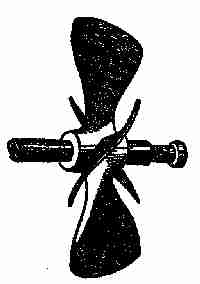
Fig. 38. Complete screw propeller
This figure shows a propeller with four blades, but two and three bladed ones, particularly for small craft, are mostly used. The Caroline carries a two bladed screw and her performances will be entirely satisfactory. The blades, of course, are exactly in line with each other on the shaft, and equally balanced, or of equal weight. A three-bladed propeller should have its extreme points in a horizontal plane, so that they will form an equilateral triangle.
The principal features of a propeller may be described as: diameter, pitch, area, speed of revolution, and slip. The diameter is that of the circle described by the tips of the blades. The pitch, considering the propeller to be a portion of a screw, is the amount which it advances in one turn, supposing it to travel in a solid medium. The blade area is the actual area of all the blades.
The speed of the revolution is customarily reckoned in turns per minute. The slip is the difference between the amount which the propeller actually advances per turn and the amount which it would advance if turning in a solid medium. For example, if the pitch of a screw is 30 in. it would advance 30 in. at each turn if there were no slip. Suppose that it only advances 20 in. per turn, then the slip is 10 in. per turn, or as usually figured, 331⁄3 per cent. As a further example, suppose a propeller of 30 in. pitch, turning 300 turns per minute, drives a boat at the rate of 6 miles per hour. The advance of the propeller in feet per minute is 30/12 × 300 = 750 while the advance of the boat is 6 × 5,280/60 = 528 ft. per minute. The slip is then 750 - 528 = 222, or as a percentage, 222/750 = 29.6 per cent. It might seem at first sight, that a perfect screw propeller should have no slip; but this is a practical and theoretical impossibility.
The most important dimension, from the standpoint of the absorption of power, is the blade area. A certain blade area may be obtained by a relatively wide blade on a small diameter, or by a narrow blade on a relatively large diameter. In the former case the area of the blades bears a greater proportion to the area of the circle through the tips than in the latter case. There are certain limits for this proportion of blade to disc area for well-designed wheels, beyond which it is not well to go. These are as follows:
For two blades .20 to .25. For three blades .30 to .40. For four blades .35 to .45.
This means that for a 24 in. diameter propeller, whose disc area is 452 sq. in. the blade area should not, for ordinary use, be made greater than these proportions, as the blades then become so wide as to interfere one with another. Of course where a propeller, for shallow draft, must be unusually small in diameter, the proportion of blade area can be increased, but with some loss in economy. Strictly speaking, for a well balanced propeller, the blade area fixes the amount of power which the propeller can deliver, while the pitch, combined with the turns per minute, governs the speed. As a matter of fact, for the average propeller the two are closely related, each having a certain influence upon the other. To illustrate, a propeller may have a small blade area and so great a pitch that the blades act somewhat like fans and simply churn the water, offering great resistance and absorbing the power of the engine, but doing little effective work toward driving the boat.
To get the measurements for a wheel required to perform a given service, say a three-bladed propeller for a small boat or tug of 20 nominal or 75 indicated horse-power:— assume that the size determined on is 4 ft. 6 in. in diameter and 7 ft. 6 in. pitch, the diameter of loss may be assumed to be 8 in. swelled to be 11 in. in the middle, and 11 in. long. The tug would be, say, 60 ft. long, 12 ft. beam, and 7 ft. deep. First delineate the path of the point and root of one blade through half a revolution as in Fig. 39. This should be drawn to a scale of not less than 11⁄2 in. to 1 ft. by the ordinary method of projecting a screw thread. The semicircle shows the half plan with twelve equal divisions, and the half elevation is divided into the same number of equal parts. The helix or thread is then obtained by drawing the curves through the intersections of similar divisions. Then a b will be the helix for point of the blade, and c d the helix for the root of the blade. These will be found to be practically straight lines which might have been obtained in a simpler manner if intended for a working drawing only; but it is useful to have demonstrated the proper nature of the full curve.
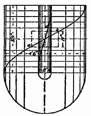
Fig. 39. Diagram screw lines
The practical way of setting off the blade follows: First for dimensions: as 20-in. (pitch) is to 11 in. (length of boss and therefore virtual length of propeller), so is 169.6 in. (circumference due to outer diameter) to the length of circumference occupied by the blade, 169.6 × 11/9 = 20.73, say 203⁄4 in. In Fig. 40 describe a circle equal to the diameter of the propeller, and on each side of the centre line step off 203⁄4 in. to half the scale, making the whole length of arc to scale 203⁄4 in. Draw vertical lines from the ends of the arc, and from the arc on the centre line set up a height of 11 in. and draw horizontal lines. Join a b, and this will be the angle of the end of the blade. On the elevation of the propeller circle describe a small circle equal in diameter to the faces of the boss; draw radial lines from the ends of the arc first found, and from the intersection with the boss circle draw vertical lines to cut the horizontal lines of the plan of boss. Join c d, and this will be the angle of the blade at the root.
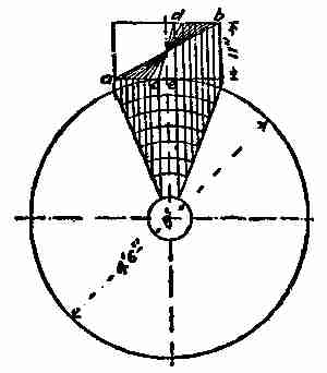
Fig. 40. Part of screw blade
Now describe an arc at every three inches from the circumference within the radical lines; or for large propellers every 6 in. Draw vertical lines from the intersections of the arcs with the radical lines to meet a c and b d, as shown, and joining the points thus found, the diagonal lines will represent the plan or angle of the blade to each 3 in. difference of radius—in other words, its real width at the different points, supposing it to be a plain geometrical portion of a screw thread. As a matter of fact, the blades are always more complex than this, the edge being curved to enter the water more easily, to avoid vibration, and also to lessen the risk of fracture in the event of striking any object in the water. Sometimes the blades are curved in the opposite direction, as if the points were being left behind while the blade is advancing.
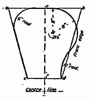
Fig. 41. Plan of screw blade
The next step is to draw a flattened elevation or development of one of the blades, in order to give the actual curves of its outline, and afterward its thickness at various points. Draw a horizontal line from c and f (Fig. 41), and through this a centre line. This will give the length of the blade from the boss, and the centre line of the propeller shaft may be added below. Then take the lengths a b and c d from Fig. 40, and set them off on Fig. 43, as shown, joining all four points. This figure would be the true outline of the blade if there were no curves. The actual outline is found by drawing the curves according to the dimensions.