PART II EVERYDAY MACHINES (continued 2)
Reading edition
An easy way out of the difficulty of explaining the formation of a raindrop, is to say that, since clouds are so often of two opposite electric potentials, there is always a continuous bombardment of watery particles taking place, and some of these must unite and fall as rain. The meteorologist is always tempted to call in electricity as an agency whenever he is anxious to discover a cause for some particular phenomenon. This often explains one mystery by another. The production of rain, snow, and hail has for many years been explained by vaguely ascribing them to the action of electricity, without any information being forthcoming as to the precise way in which this action takes place. Meteorologists are at present attempting to find a more satisfactory explanation. Another theory is that the particles of moisture in a cloud, like all other objects, radiate heat, and, growing cold, condense moisture upon their surfaces, thereby increasing in weight until they assume the proportions of a drop. This seemed a reasonable explanation of the formation of a rain drop until modern research decided that whenever moisture is condensed, latent heat is set free, so that all moisture deposited on a watery particle only serves to raise its temperature, and cause evaporation of the moisture thus acquired. The particles of water could not by this means grow to the full estate of a rain drop, and the theory is being gradually abandoned.
A rain drop is, according to modern meteorologists, explained in a very simple way. It has been seen how the hot, damp air is formed into a cloud, and also how the minute particles of water at once commence to fall slightly earthwards. Now these little particles as they pass into a warm layer of air would soon be evaporated, and would never reach the earth at all. Their downward journey, however, is often through a cloud many miles thick, and the most modern and simple theory is that in this journey they overtake some of their fellows, and the joined particles increase their rate of travel, overtake more and more particles until they presently become heavy enough to take the final plunge to earth. Were it possible to be just beneath a cloud, an observer would see rain drops coming from it of all sizes. The same process goes on in drops, which trickle down a window pane, or in the effervescing globules in a bottle of seltzer water. In the latter instance, the process is reversed, for the globules are seen overtaking one another in an upward direction. There are many points in favour of this theory of the formation of rain drops, and at least it gets rid of those elaborate complications, electricity and condensation. With respect to the formation of rain by the impinging of clouds upon the tops of cold mountains in the northwest, one authority argues that moisture is in these circumstances not condensed solely because of the contact with the cold hills; that rain there is due to a mechanical cause, the watery particles being squeezed together by the grinding effect of the clouds on the sides of the mountains in such a way that they coalesce, and fall as drops.
A rain drop's roundness is due to the action of capillarity. Just as a circle made by dropping a stone into water owes its shape to the fact that the force is able to act equally in all directions, so a rain drop is spherical, owing to similar untrammelled action on the part of capillarity. These are some of the explanations of the formation of a rain drop, but meteorologists still have the subject under consideration.
The periods of rainfall are divided broadly into times of drought and times of flood, and it is in these matters that meteorology is seen in its practical aspect. Some people ask, "Where does all the rain come from?" Others are surprised that rainfall totals up to such large quantities.
A fall of rain to a depth of one inch over a very limited area, represents millions of gallons, but in spite of this vast quantity of falling water, many times multiplied if the annual rainfall be taken into account, there still are water famines. The question has often been debated whether man can modify climate or effectively tamper with the processes which produce rain. Rain making has not, so far, been a success, though the firing off of heavy guns has been tried, along with the legitimate avocations of the meteorologist. The afforesting or deforesting of a district has, however, a marked effect upon rainfall. Three notable instances are Ascension Island, Malta, and the neighbourhood of the Suez Canal, where the planting of trees seems to have had the result of increasing the rainfall. The effect of trees is felt more in the storage of rain water, while leaves and roots serve to retain moisture that would otherwise quickly drain away. A hill may be converted into a sponge by the judicious planting of trees. The question of the storage of rain water becomes more pressing each year, and the longer the settlement is put off, the more difficult will decision become. Engineers called upon to prevent floods and to conserve rain water reply, "Save our forests, cover the land with trees."
The fact that such problems arise, serve to show how great is the amount of water formed by the continual falling of the tiny raindrops. As long as this beneficent downpouring is allowed to drain away unused or uncontrolled, so long will droughts annoy and water famines bring distress.
In recording weather conditions, symbols are sometimes used in order to shorten reports and, while not universal, most nations adopt these: The symbol for rain is ●, a small circle filled in; for lightning ; for thunder T, while the two latter combined make T, the symbol for a thunder-storm. Nearly every weather component has a distinctive symbol, and since a great part of the meteorologist's work consists in going over records of observations to search for the number of times the different phenomena occur during each week or month, the task is much simplified when observers employ the symbols, as it is easier to pick out a symbol from a printed or written page than it is to recognize a word. These symbols, moreover, have been agreed upon as a sort of international notation, and make it easier for the meteorologists of different countries to understand the records of foreign meteorological services.

Everybody does not know the Russian word for snow, or the Dutch for hail, or the Bosnian for rain, but all who run, may read when "snow" is universally written, and hail represented by a wedge-shaped figure with lines drawn across. Time and space being limited, nearly all published records of weather merely set forth the number of days throughout the year on which the different phenomena occurred, and should snow, hail or thunder happen two or three times in one day, it would still be counted only as one day. The yearly totals, therefore, show the number of days on which these conditions have been observed. It is now an almost universal custom to count .01 inches or more during the twenty-four hours as a day of rain. Accordingly, where observers read their rain-gauge to three places of decimals, that on which less than .005 inch fell would not be counted as a rainy day. Smaller amounts would, however, be included in the total. Dew may sometimes fall to the amount of .01 in. or more; and that is counted as a rainy day, the rule being to consider the amount of precipitation, irrespective of the manner in which it has fallen. If you wish to make these observations comparable with published records you would do well to conform to these rules.
HAIL
Hail, the next weather component to be considered, presents many difficulties when the attempt is made to explain its origin and formation. Those who have anything to do with scientific matters are well acquainted with the hypothesis, which explains a given fact, and in considering the subject of hail, the meteorologist hears of many hypotheses which are put forward as complete explanations of this phenomenon. Caution is, therefore, to be exercised and every reported statement severely questioned. Remembering the aphorism: "The man or boy who never makes a mistake will never make anything," meteorologists have attacked the question of hail formation, and, although many mistakes have probably been made, the subject has lost a good deal of its mystery. For many years, it was customary to be content with a recognition of the fact that hail and lightning very often occur together, and the conclusion was drawn that the one was in some way responsible for the other. Sufficient corroboration of this hypothesis was to some meteorologists, found in the fact that thunder and lightning are said to be almost unknown in the Arctic regions, and this supposed companion, hail, almost unknown. Roughly speaking, the assumption was that lightning, as it flashed through a cloud laden with watery particles, caused hail to form. Such an explanation only tended to make the subject more mysterious, and the question, How is hail formed? practically remained unanswered. Many simpler explanations of hail have been propounded as the result of modern research, and, like rain and lightning, it has been demonstrated that hail owes its origin to the movement of the minute watery particles found everywhere in the atmosphere.
The clouds from which hail fall are ordinarily of great height above the earth, 40,000 feet or even higher. These are the well-known cirrus. The first condition necessary to the formation of hail is a powerful ascending current of hot, moist air, which may condense its moisture in the shape of the large woolly cloud, known as cumulus. Such a cloud may be 100 cubic miles in volume, and as long as it retains its shape nothing is likely to fall from it to the earth beneath. Before the formation of a thunder-shower, cirriform fibres in some instances break away from the upper portion of this cloud, the electrical tension is lowered, and rain falls. The coalescing of the particles of moisture has a great deal to do with the changes which take place in a cloud. All these changes take place in the higher clouds in a marked degree, and the varying strata through which the watery particles pass in ascending to and descending from this great height bring about the violent change essential to the formation of hail. The necessary conditions for hail are, therefore, a powerful, hot, ascending current of air and great variation in the strata of the atmosphere as regards moisture and temperature. Mountains assist in forcing currents of air upwards, and one mass of air impinging on another is also thrown upwards, so that condensation of moisture rapidly takes place. A hail cloud may be described as a tower of hot air, from the top of which, vapor is ejected into a frosty region. Hot plains are accordingly the most favourable spots for the formation of hail, and in mountainous districts, more hail falls at a distance from the mountains than among them. Snow is observed in all latitudes and at all heights, but hail is confined to middle latitudes, and is rare in high latitudes. The places most affected by hail are those in which, the temperature and humidity of the air are high, while above, at a great height, there is a cold area below the temperature of freezing point; but, as in the case of the rain drop, before anything can be definitely stated, it must be shown how the particles of moisture coalesce to form hail.
SNOW
Snow is frozen water which falls instead of rain when the temperature is below the freezing point. The ultimate constituents of snow are tiny, six-pointed crystals of ice. They assume in combination a thousand different figures (Fig. 210), all exceedingly beautiful. Professor Tyndall has shown, further, that the ultimate particles of ice are also these six-pointed stars. The white colour of snow is caused by the commingling of rays of all the prismatic colours from the minute snow crystals. Separately the crystals exhibit different colours.
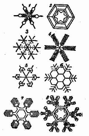
Fig. 210. Snow crystals
Snow is usually from ten to twelve times as light as water, bulk for bulk; so that where the snow falls pretty evenly, the corresponding rainfall is readily determined by merely measuring the depth of snow and taking one tenth of the result. The more accurate plan, however, is to thrust the open end of a cylindrical vessel into the snow, invert the cylinder, and then melt the snow in it.
Snow plays an important part in the economy of nature. In the first place, the mere transformation of the water particles into ice is a process during which a large amount of heat is given out; so that we may regard the formation of snow renders the air currents warmer than they would otherwise be. Fallen snow serves to protect the ground, for, owing to its loose texture, it is a bad conductor of heat; so that, while checking the radiation of heat from the earth into space, it does not draw off the earth's heat by conduction. The ground is thus often 23 degrees to 30 degrees warmer than the surface of the snow above, and sometimes the difference of temperature has been more than 40 degrees.
Red snow and green snow have been met with, more commonly in Arctic regions, but also in other parts of the world. These colours are caused by the presence of minute organisms—a species of alga called Protococcus nivalis.
The snow line of mountains is on the slopes below which, all the snow which falls in the year, melts during the summer. Above the snow line, therefore, lies the region of perpetual snow. The altitude of the snow line depends on a variety of conditions. The latitude of a snow range is, of course, important in determining the position of the snow line, but many other circumstances have to be considered, as the shape and slope of the mountain, the aspect of either side of the range, the character of the surrounding country, the prevalent winds, and so on.
The following table shows the observed height of the snow line in feet above the sea level in different places:
Place Latitude Height
Spitzbergen 78 N 0.
Sulitelma, Sweden 67 5´ 3.835
Kamtchatka 59 30 5.240
Unalaschta 56 30 3.510
Altai 50 7.934
Alps 46 8.885
Caucasus 43 11.063
Pyrenees 42 45 8.950
Rocky Mountains 43 12.467
North Himalaya 29 19.560
South Himalaya 28 N 15.500
Abyssinian Mts. 13 14.065
Purace 2 2´ 15.381
Nevades of Quito 0 15.820
Arequipa, Bolivia 16 S 17.717
Paachata, Bolivia 18 12.079
Portillo, Chili 33 14.713
Cordilleras, Chili 42 30 6.010
Magellan Strait 53 30 3.707
DESIGNING, MAKING, AND INFLATING PAPER BALLOONS
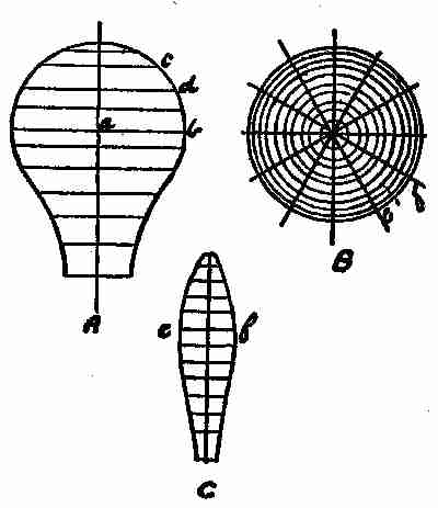
Fig. 211. Paper balloon
Draw a rough figure of the balloon, as shown at A, (Fig. 211.)
Divide this into any number of parts (the more the better) by horizontal lines. Take a radius of balloon on each line, and describe circles, B.
Divide this into twelve parts by radius lines, then make pattern as follows: Draw a perpendicular, C, with horizontal lines at distance of horizontal lines on A, but measured on circumference as c d. Then set off on each line from perpendicular one half the distance between the radius lines, B, on the corresponding circle as e f; draw line through points thus found, and result will be shape of each section. Allow a little on one side when cutting out for pasting. This will be best made with strong tissue paper of any colour desired.
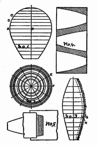
Fig. 212. An improved balloon
Another method, giving a shape somewhat different, is shown in Fig. 212. First draw an elevation of the balloon it is intended to make, either full size, on the floor, or to scale. The shape here illustrated differs slightly from that of balloons usually sold ready made, being wider at the mouth. This shape, however, is not so liable to catch fire when swayed about by the wind. Divide the elevation into any number of parts (the more the better) by horizontal lines as shown (No. 1). Take the radius of the balloon on each line, as A B, describe circles (No. 2), and divide these into twelve parts by radial lines. Then to make a pattern, draw a perpendicular (No. 3), with horizontal lines at the distance of the horizontal lines (No. 1,) but measured on the circumference as C D. Then set off on each line from the perpendicular half the distance between the radius lines (No. 2), on the corresponding circle as E F, and draw a line through the points thus found, and the result will be the shape of each section. Allow a little (say 1⁄4 inch), on one side when cutting out for pasting. Each section will be made up of one, two, or three pieces, according to the size of the balloon to be made. If the pieces are cut as shown (No. 4,) a great saving of paper results. To paste these pieces together, place them in a pile on the table or bench with the edges flush and a piece of waste paper under the pile. Now rub the top sheet with the thumb nail until each piece is moved back from the one immediately under it about one-fourth inch. Place a piece of waste paper about the same distance from the edge of the top sheet, and pass the paste brush over the whole of the exposed edges. No. 5 will explain what is meant. Now place two of the completed sections together so as to look like No. 3, with a small part projecting as shown by the dotted line G. Paste the edge of the under section—that is, the part hatched—and turn it over on to the dotted line H. When each two of the sections have been joined in this way, proceed in the same manner to join these together till the whole is completed. A circular piece of paper is cut out to join the sections at the top, and a loop of string should be pasted to the top to suspend the balloon while inflating. A ring of wire with two cross pieces is fitted to the bottom of the balloon, and the inflammable material,—tow soaked in methylated spirits—is fastened to the junction of the cross pieces.
MAGNETIZED WATCHES
The owner of a good American watch was a little troubled concerning it, because it had been running irregularly for some time past. It came out that he had visited the electric power house and had stayed for some time examining the works and machinery, so that parts of his watch had evidently become magnetized by the influence of the dynamos. The watch had been made some time ago, and had not the power to resist, or neutralize electric influences, that most watches have now.
To demagnetize the watch would bring it back to its original condition, but a second visit to the lighting plant would again spoil its time-keeping qualities. The watchmakers now have a way of making watches so that they are not affected by magnetism, but comparatively few of the time pieces in use are non-magnetic, and the average watch is subject to these seasons of fickleness.
The exceedingly fine and exact construction of the watch is not realized by the average possessor of the article. An examination of the works of a watch shows the mechanism as now constructed, although very small in size, to be accurately planned and executed. Changes of temperature are provided for, so that the movement is automatically adjusted. The mainspring and train of gears are usually concealed, while the balance and hair springs are in full view when the case is open. Upon the regularity of the movement of the balance depends the time keeping quality of the watch. On looking closely at the balance, you will observe that it is not a complete ring, but two halves supported at one end. These rings bear a number of large-headed screws, placed at irregular distances, which give it the exact weight and balance required. These half rings will also be found, on looking closely, to be composed of two metals so closely joined that a difference in colour alone gives evidence of the quality. This arrangement of iron and brass, on account of their different coefficients of expansion and contraction with changes of temperature, has been so carefully constructed that, with changes of temperature, the balance assumes such forms as to give it a uniform rate of motion.
The parts affected by magnetism are the balance and springs. The balance in an ordinary watch moves five times a second, 18,000 times an hour, and 432,000 times each day; but a slight change in the forces that move it is necessary to make a difference of several minutes each day. As the balance moves back and forth, the magnetism of the mainspring is pulling or pushing it. If this force were constant, and always in the same direction, the watch would run uniformly. Such, however, is not the case. When the mainspring is tightly wound, its magnetic poles are in a certain direction, and in unwinding they are constantly changing, so that the direction of this force is also constantly changed. The effect on the balance is to cause the watch to run too fast sometimes, and too slow at other times.
Non-magnetic watches are made with these parts of a non-magnetic metal, so that they are not influenced by electric machinery. For testing watches a small compass is used. When placed over the balance, the needle will vibrate with the motion of the balance in proportion to its magnetism.
A BOY'S WHEEL-BARROW
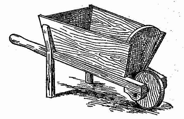
Fig. 213. A boy's wheel-barrow. Perspective view
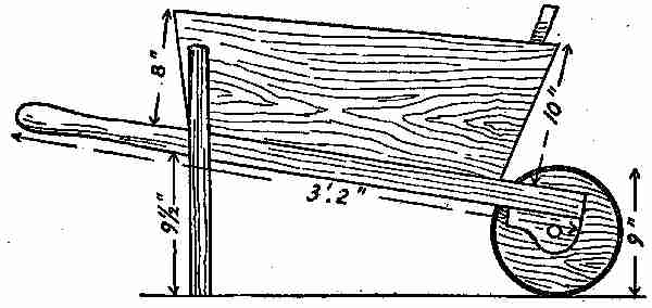
213 A. Boy's wheel-barrow. Side elevation
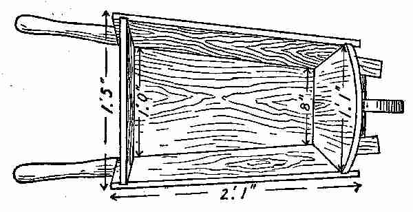
213 B. Finished plan
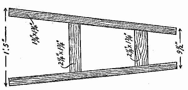
213 C. Plan of frame
The bottom, sides, and ends were about three-quarters of an inch thick. Good white and red pine were used for the purpose. The stiles and rails of the bottom framework were mortised and tenoned together as shown at Fig. 213; these may be just stubbed together, or the tenons of the rails can go right through the stiles. The most satisfactory job is to groove the sides and ends together, and put all together with oil paint in the joints. If the joints are painted before the framework of the barrow is put together, it will last for years; otherwise, being a boy's wheel-barrow, it would likely often be forgotten and left out in the rain, and the joints getting wet would hasten decay. Two coats of good oil paint, Indian red, will give it a very nice appearance. This barrow, while not intended for heavy work, is capable of carrying quite a load. The wheel was cut out of a piece of plank about 11⁄2 inches thick, hooped up with an iron tire made from heavy hoop iron. The axle was made of wood with a 3⁄4-inch round iron rod running lengthwise through it and projecting about three inches through on each end. The arbours or boxing, in which ran the ends of the round rod, were formed on the ends of the handle stiles, as may be seen in the illustration. The cost of all the materials for this really useful article was less than $1.50, all told.
VACUUM CLEANERS
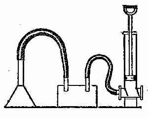
Fig. 214. Home-made vacuum cleaner
A single hand vacuum cleaner can be made from a powerful suction pump, as indicated in the sketch Fig. 214. This should be connected with a metallic box by means of a flexible armoured rubber hose, covered at the end with a piece of fine wire gauze to prevent large particles of dust, etc., being drawn into the pump. To another opening of the box should be fastened another flexible rubber tube, with a bell-shaped metal attachment at the end. The bell-shaped arrangement should be held closely to the carpet while the pump is in action. Within the box, the pipe to which the pump is attached should be bent upward, so that the rush of air shall not bring the dust with it; the object being to collect the dust in the box. A lid covers the box so that it can be emptied from time to time. The success of this arrangement depends on the strength of the pump; if it be a weak one, the inrush of air through the funnel will be so slight that the dust will not be raised.
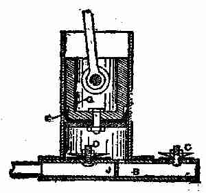
Fig. 215. Metallic vacuum cleaner
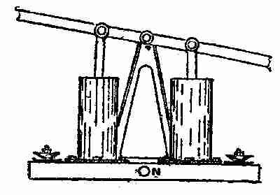
Fig. 216. Simple vacuum cleaner
Rotary pumps are not satisfactory for vacuum cleaners. The best type for this work is a plunger, having a large displacement, with a comparatively short stroke in proportion to the diameter. A suitable pump is shown in the accompanying illustrations. Fig. 214, shows the section of a single barrel, but should a greater supply be required, two barrels may be worked and connected as shown in Fig. 216. The pump is easily made, and of light construction. In Fig. 215, is a brass cylinder with a flange at the bottom; this may be made out of a length of 3-inch brass tube with a flange cut from 1⁄8-inch sheet brass. The barrel is 8 inches long. G is the plunger, which may be constructed as a piston; but in the drawing, it is adapted to the arrangement that is shown in Fig. 216. With a piston will be required a guide for the rod at the top of the cylinder. E is a hydraulic cup, its leather kept soft and pliable by oiling. B is the base, which is hollow, and may be built up in sheet metal. At the centre at J, the base is divided into two compartments, one side being the inlet to the pump from the dust box, and the other in communication with the outlet valve C. C and D are two valves with guards. The valves are discs of very soft and pliable leather, well saturated with grease, D being the inlet from the dust box, and C the outlet to the atmosphere. The drawing clearly shows the construction of the other parts. Fig. 216 shows two pumps fitted to one base and worked by a rocking lever; both pumps are in communication with the one inlet N. This arrangement of pumps is easy to work, portable, and well adapted to domestic purposes in cleaning carpets.
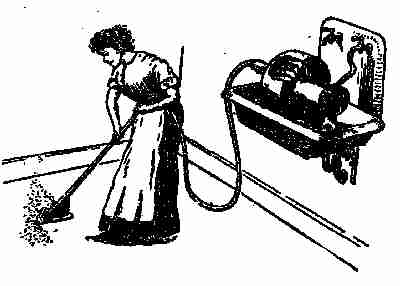
Fig. 217. A motor vacuum cleaner
Fig. 217, which is reproduced from The Scientific American, exhibits an ingenious form of vacuum cleaner. It has recently been patented, and consists of a suction-fan operated by a water-motor that may be attached to the ordinary kitchen faucet. A tube is connected with the chamber of the suction-fan, and this terminates in a suitable nozzle, or foot plate, which may be moved over a carpet or rug to draw out the dust and dirt. One of the advantages of this system is that dirt drawn up by the suction fan can be carried away with the water down the kitchen drain.
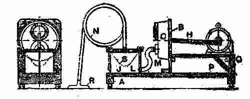
Fig. 218. Home-made power-driven vacuum cleaner
A good power-driven cleaner may be made at home, says Popular Mechanics, by following these directions: First take a good pine board, 1 inch thick, 1 foot wide, and 3 feet long, and nail to each end a 1-foot length of 2-inch by 2-inch pine, as shown at A, Fig. 218. Next a 3⁄4-inch board, 1 foot wide and about 1 foot, 3 inches long, should be fastened near the centre, and at right angles to the first board, as shown at B. Procure a tin pan measuring about 10 inches in diameter and 3 inches deep. This pan shown at C, must be fitted with two valves, which are the most important and difficult part of the work. Cut, from a smooth piece of pine, 1 inch thick, two discs, 5 inches in diameter, with a 3-inch hole in the centre of each. Obtain a sheet of packing rubber, 1⁄8 of an inch thick, and cut from it two discs, each 5 inches in diameter, and two 31⁄2 inches in diameter. One of the discs of wood should be fastened to the back of the pan at the top, as shown at D, Fig. 219, with one of the 5-inch diameter rubber discs placed between the tin and the wood, and both secured to the tin by a row of small bolts around the outside edge of the wood. A hole, 3 inches in diameter, can now be cut through the tin and rubber, using the hole in the wood as a guide. Two discs with a diameter of 31⁄4 inches should be cut from cigar box wood and fastened centrally on the 31⁄2-inch rubber disc. One of the latter pieces should be fastened by its top edge to the top edge of the 5-inch disc of wood, as shown in E. This forms a flap valve, and great care should be taken to see that the rubber disc covers the opening all the way around when the valve is closed, so that it will be air-tight. A spring will be necessary to quicken the action of this valve. This is best made by fastening a narrow strip of wood across the valve opening on the inside of the pan, as shown at F, and attaching a rubber band to the centre of the valve and to this stick. This completes the outlet or exhaust valve. Another valve must now be made in the same manner, and fastened to the bottom of the pan on the inside, as shown. This is the inlet valve, and works in the opposite direction to the outlet valve just described.
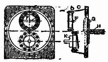
Fig. 219. Home-made, power-driven vacuum cleaner
Next procure a piece of leatherette about twelve inches in diameter, or large enough to cover the opening of the pan. This is to be used for the diaphragm. Cut a round hole about 8 inches in diameter in the upright piece B (Fig. 218), its centre about 7 inches from the top. From a piece of 1⁄2-inch pine, cut two discs 6 inches in diameter. Also secure a piece of hardwood H 1 inch by 1 foot 2 inches. The discs G should now be placed, one on each side of the leather diaphragm, exactly in the centre, and fastened to one end of the 1-foot 2-inch piece by means of a long screw. This piece H should exactly be in the centre of the diaphragm.
The pan can now be put in place. Set the diaphragm over the hole in the board B, the stick projecting through the hole. The pan is now placed over the diaphragm, and held by means of small bolts around the edge. The diaphragm between the wood and the tin acts as a gasket, and makes an air-tight joint.
Secure an air-tight tin about 8 inches in diameter and 12 inches high, and fasten it to the base board, as shown at J, Fig. 218. The cover of a coffee tin should now be soldered over the inlet valve, as shown at K, Fig. 219. Solder a hose connection in the centre of this cover, also one in the side of the tin, as shown at L, Fig. 218. Couple a short piece of hose M to these connections. The strainer S should be made of very strong and closely woven unbleached drill. Make it in the form of bag with a 1-inch hem at the top, and place it in the tin, as shown by the dotted line, the hem fitting closely over the inside edge of the tin. The cover of the tin is made from a flat pine board about one inch thick, and is held in place by two 1⁄4-inch rods fastened in the base board. These rods have thumb nuts on the top, which allow the cover to be readily removed or tightened down. It is best to place a rubber or leather gasket between the cover and the edge of the tin so as to make an air-tight joint.
An air-tight piece of garden hose can be used for the suction hose N, one end being fastened in the centre of the cover and the other to the brush or nozzle R, Fig. 218. It is best to buy this nozzle, as it would be rather expensive and unsatisfactory if home-made.
This machine may be driven by an electric motor of about 11⁄4 horse-power, which should be placed in the position shown in Fig. 218. The end of the connecting rod H is fastened to a crank on the motor shaft, and allowed to have about a one and one half inch stroke. The motor is wired up with a switch, P, and it would be best to connect to a rheostat, to allow the regulation of speed best suited to the machine. This can readily be determined after the machine is started. If an electric motor is not available, a small water motor will do equally well; or it may even be run by hand, by means of a long lever, fulcrumed at P.
The machine is now ready for using. First, however, test it all over for leakage, as its success depends on its being perfectly air-tight. As the motor revolves, the rod H is drawn forward, bringing with it the diaphragm. This creates a partial vacuum in the pan C, which opens the inlet valve, sucking the air through the suction hose and strainer, the air carrying with it the dust and dirt. The refuse is left in the strainer bag while the air goes on through the connecting hose and pan and outlet valve into the atmosphere. After the article being cleaned has been gone over thoroughly, care being taken to hold the nozzle against the material, the cover may be removed and the bag emptied.
IV MOTORS AND TYPE-WRITERS
MOTORS, GASOLENE AND STEAM—AUTOMOBILE FRAMES—THE MODERN TYPE-WRITER—DIRECTIONS FOR SECURING COPYRIGHTS.
There are two classes of heat engines in use; in one class the combustion takes place on the inside of the cylinder or generator, just as fire is applied to a tea-kettle, and the heat is transmitted by conduction through the metal walls to the part of machine doing the work. Motors and machines of this kind, are generally called "external combustion" engines, of which the steam engine is a prominent example.
Engines where the combustion takes place inside the machine itself, and acts directly on it, are engines of the second class, termed "internal combustion engines." The gasolene engine is of this type, and so are all gas and oil engines.
The principle of the motor-cycle engine, in its action, is similar to the regular automobile engine and the gas engine. All these are internal combustion or explosion engines; that is, their motive power is derived from the force exerted by the explosion of a gas while under compression, the compressed gas generally ignited by means of an electric spark. In the case of gasolene motors, the gas is obtained from the liquid gasolene, either by allowing air to be drawn through it or by spraying the spirit through a small hole, the latter being the method most generally used. A great quantity of air has to be mixed with the vapour before it will ignite. The amount that is required varies considerably, atmospheric conditions and the height above sea level causing variations in the demand. The action of the common gasolene engine is known as the "four-stroke-cycle," that is, there are four strokes of the piston for every impulse, one being a "power" stroke and the other three "duty" strokes, as it were. Each performs a certain operation that is necessary for the correct working of the engine. Some engines are worked on the "two-stroke-cycle" principle; in this case, there are only two strokes for each impulse. This type of engine has many disadvantages, and there are very few two-stroke engines in use for driving motor cycles.
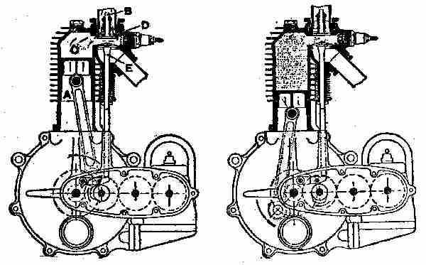
Fig. 220. Suction stroke begun Fig. 221. Compression stroke begun
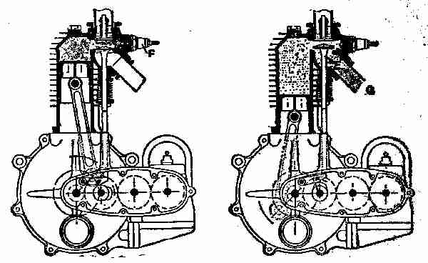
Fig. 222. Power stroke begun Fig. 223. Exhaust stroke begun
The principle of the "four-stroke-cycle" is shown in Figs. 220 to 223. In Fig. 220 the piston A is just beginning the downward stroke, and the valve B is opened by the pressure of the atmosphere, or by mechanical means. The piston in descending causes a partial vacuum in the cylinder head or top C, which allows the atmospheric pressure on the surface of the gasolene in the carburetor to force some of the liquid through the spray hole, thence through the inlet-valve opening D, into the compression space of the engine cylinder. The suction of the piston does not bring in the explosive mixture of gas and air; it is the pressure of the atmosphere that causes the mixture of gas and air to rush into the cylinder. Just before the piston is at the extreme end of the downward or outward stroke, the inlet valve B is closed by the spring shown, and the piston begins the first upward or "compression" stroke with both the inlet valve B and the exhaust valve E closed. The charge is being compressed when the piston is on its upward stroke, as shown in Fig. 221. Speaking generally, soon after the piston is over what is known as the "dead centre," and is about the position shown in Fig. 222, an electric spark is made to jump across two points of the sparking plug F; this ignites the mixture of gas and air (which is at a pressure of about 80 lb. per sq. in.), and the explosion causes the piston to descend on the power stroke. Just before the piston reaches the bottom of the power stroke, the exhaust valve E, Fig. 223, opens, and remains open during the upward stroke. The momentum of the flywheels, etc., carries the piston upward, and thus forces out the burnt gases through the exhaust opening G, and from there to the silencer. Immediately the piston begins its next downward stroke, the inlet valve opens, fresh air is drawn in, and the cycle of operations is repeated as before. The illustrations show a magneto gear driven by the engine.
These engines when properly arranged are made to do service as marine motors, and are then installed either horizontally or vertically. A vertical engine has been shown on previous pages, but perhaps a little further explanation may not be amiss. Engines for boats are made with one cylinder or with more, and there are many considerations which make an engine of two or more cylinders particularly desirable. It is a self-evident fact that when the limit of size of a single-cylinder is reached, it is necessary to add other cylinders if greater power is desired. Even for moderate or small powers, there are many advantages. Among these may be noted the fact that with the proper arrangement of cylinders the impulses may be made to occur at shorter intervals than with a single-cylinder engine. Thus with a two-cylinder engine, the cylinder may be so arranged that the impulses will occur twice for every revolution instead of once, as in a single-cylinder. This gives a more even turning effect to the shaft, and consequently steadier running, and it also requires a less heavy fly-wheel. The vibration is much less, as one set of working parts may be made to travel upward while the other is travelling downward, thus neutralizing the throw of each and lessening the vibration.
In case of the disablement of one cylinder, there is the chance of getting home on the remaining ones. The weight, power for power, of the multiple-cylinder engine is less than that of the single-cylinder engine, as the weight of the fly-wheel and other working parts is less.
While for marine work, single-cylinder engines have been built as large as eight or ten horse-power, they are so large as to be rather cumbersome and the practice now is to build engines of more than six horse-power with two or more cylinders. There are several firms who are making double-cylinder engines as small as four horse-power, which both as to weight and reliability are much superior to those of a single-cylinder.
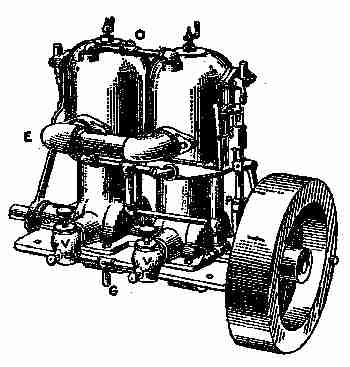
Fig. 224. Two-cylinder engine
The original method of constructing a multiple engine, and one which is still used by some builders, is simply to use two or more single-cylinder engines coupled together. This is a cumbersome method and takes up a great amount of space. The simplest method which can be recommended is that shown in Fig. 224. It consists of two single-cylinders mounted on a common base of special design, bringing the cylinders much nearer together than when a coupling is fitted to connect two separate engines—as the shaft can be made in one piece. This particular engine is of the two port type, two vaporizers V-V being used. The gasolene enters at G and branches to each vaporizer. The pump is shown at P with the discharge at W, piped with a branch to each cylinder. The cooling water outlet is at O. The exhausts are connected to a common pipe with the outlet at E. The igniting gear for each cylinder is independent and on opposite ends. By means of the lever L, which is connected to both igniting gears, the time of ignition is regulated and kept the same on both cylinders. This allows multiple-cylinder engines to be built with very few extra parts, as the cylinders, ignition gear, etc., are the same as in the single-cylinder engine.
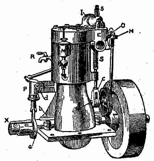
Fig. 225. Single-cylinder engine
A view of a representative single-cylinder engine is shown at Fig. 225. The cam shaft is located at a and is driven by the gears which are shown just in the rear of the fly-wheel. At c are the cam and the roller, which actuates the exhaust valve. The cam consists of a collar with a flat projection or toe upon its surface; the roller rests just above the surface of the collar, and is forced upward when struck by the projection. The roller is inserted to lessen the friction by rolling instead of rubbing. The valve stem extends upward into the valve chamber, and is encircled by the coiled spring e; the stem is guided by the guide at g. The exhaust is at E; I is the pipe leading from the vaporizer V to the inlet port in the valve chest. The inlet valve is directly below the spring S and is inverted, being held in place by the spring. The dome-shaped cap containing the inlet valve is removable for access to both valves. The complete cover is also removable. It will be observed that this engine has an open frame very similar to that of a steam engine, giving free access to the crank-pin and main bearings; the latter are shown fitted with oil boxes b instead of the grease cups, as there is no pressure tending to force the oil out along the shaft as in the two-cycle type. This open base not only makes the bearings more accessible, but renders it easier to lubricate them and keep them cool. At H is the ignition gear. P is the cooling water pump, run by the eccentric e. The suction is piped to d and the pump discharges through the pipe k into the cylinder. The outlet for the cooling water is at O; N is the cylinder oil cup for oiling the bore of the cylinder. The compression cock R is for relieving the compression at starting. The coupling at X is for attaching the propeller shaft.
In this engine, the cylinder, base and bolting flange are one casting, the upper half of the main bearing being removable for the insertion of the shaft. The cover is bolted on separately.
AUTOMOBILE FRAMES
The chassis for the single-cylinder, eight horse-power motor machine shown herewith is built on the principle of most frames, of any make and is typical of the majority of light motor car chassis at present in use.
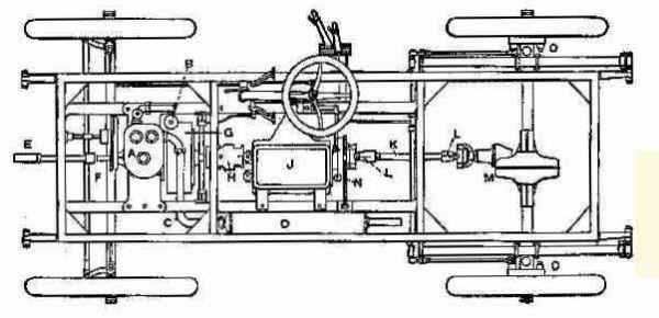
Fig. 226. Eight horse-power single cylinder chassis
A diagrammatic plan of the eight horse-power, single-cylinder chassis is shown in the accompanying illustration (Fig. 226) in which, A indicates parts enclosed, taking the mixture of gasolene and air from the float-feed spray carburetor B, which has an automatic air regulator. The purpose of this last device is to dilute the mixture when the engine has a light load and is inclined to race; generally speaking, this regulator serves to proportion the ingredients of the explosive mixture to the requirements of the engine. Current O for the ignition of the explosive mixture (ignition occurs once for every two revolutions of the fly-wheel), is supplied by an accumulator and intensified by a high-tension coil. The products of combustion pass through the exhaust pipe C to the muffler D, from which they pass to the atmosphere through a series of fine holes. The starting handle E makes a simple connection with the end of the motor shaft F when required. G is the fly-wheel. The drive from the engine is through a universal joint H to the change-speed gear J, the latter consisting of two trains of toothed wheels, a big wheel on the primary shaft gearing with a small one on the secondary shaft to give a high speed, and vice versa. From the change-speed gear, the drive is through a shaft K, having a universal joint L at each end, to the bevel gearing above the differential gear of the live rear axle. Bevel gears and the differential gear are all contained in the casings M. Three brakes are fitted, one operated by pedal, working on a drum N secured to the propeller shaft, the others operated by the side lever and working on drums O O, secured to the rear wheels. The change-speed gear gives three speeds forward and a reverse; the frame is of pressed steel; the rod and wheels are of the artillery type and carry 700 mm. by 85 mm. pneumatic tires. The gasolene tank holds 41⁄2 gallons, sufficient for 200 miles, and the lubricating oil tank holds 1 gallon, sufficient for 350 miles. Any beginner in motoring matters, who studies the diagram, will obtain a fair idea of the mechanism of the customary type of light car chassis.
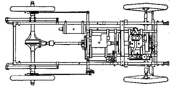
Fig. 227. Plan of chassis of light racing car—two-cylinder motor
A chassis, suitable for a 71⁄2 horse-power quick-speed, two-cylinder motor, is shown in Fig. 227.
It is not necessary to enter fully into the details of construction after describing such a typical gear-driven car as that at Fig. 226.
The frame A is of tubular steel, there are four semi-elliptic springs, and the artillery wheels have 28-inch by 3-inch tires. The two-cylinder engine B is one casting, with a large waterway covered by an inspection plate C. The bore is 3.5 inches, stroke 4-inches, cylinder capacity 76.9 cubic inches, and the piston displacement is 92.300 cubic inches per minute. A governor automatically throttles the inlet when the motor attempts to race, but by means of a lever the governor can be cut out and the motor accelerated from its normal speed of 1,200 revolutions per minute. The balanced crank has but a single throw; the water circulation is assured by a motor-driven pump, and there is a belt-driven fan behind the radiator. The commutator is easily accessible, being mounted on a bevel shaft lying in a sloping position and passing through the side of the crank chamber. Ignition is high tension with wide contact, the wiring being enclosed in a neat wooden casing. The change-speed gear D gives three speeds and a reverse, and its main bearings are fitted with ring lubricators. A pressure sight feed lubricator on the dash-board has three outlets, one to the engine, another to the main clutch, and a third to the driving pinion on the end of the propeller shaft. The brakes are of the usual kind. In Fig. 227, E is the carburetor, F the inlet and G the exhaust pipes, H the exhaust muffler, J the brake pedal, K the clutch pedal, L the band-brake on the propeller shaft, and M the internal expanding brakes on the wheel hubs. A shield is arranged under the front of the car to protect the mechanism from mud and dust. The weight of the car unladen is about 1,414 pounds, the wheel base is 731⁄2 inches, the track 46 inches, and the over-all dimensions are 111 inches by 60 inches. During a 600-mile trial this engine consumed 36 gallons, 6 pints of gasolene, this being at the rate of 1 gallon for every 16.9 car miles; .077 gallon was consumed every ten miles.
THE MODERN TYPE-WRITER
Every home of importance contains a writing machine of some kind, and these often require some little adjustment or "fixing." It is within the capacity of any bright boy to make these adjustments, or to do the little fixings, if he tries it earnestly.
The first marketable type-writer was introduced in the year 1875. No sooner had the type-writer acquired a commercial value, than the fire of inventive talent was awakened in Europe and America, and type-writer after type-writer appeared on the market—a few came to stay, but the many disappeared, either during the chrysalis or experimental stage, or shortly after it had been passed. Inventors and investors have learned that hasty innovations and untried experiments spell "failure" in the type-writer field, and only patient and careful study, backed by experience, tireless effort, and abundant resource, have a chance of success.
By the year 1888, there were six different kinds of machines in the market, to-day there are at least twenty, but the favourites seem to be, "The Remington," "Smith Premier," "The Underwood" and "The Oliver."
Modern type-writers may be defined as being tabulating, book recording, card indexing, and document writing machines. They are speedier and produce finer and more varied work than their predecessors.
The manner in which the type-writer performs its work is of the simplest. The type-writer may be considered as composed of three general parts, as follows:
The keyboard, by which the operation of the machine is directed.
The type mechanism, by which the desired letters are, one after the other, in any desired sequence, imprinted on the paper.
The carriage, which holds the paper in proper position for writing, and which, by its regular movements, provides for the spacing of letters and lines.
The Remington may be considered the pioneer of writing machines. In appearance the Remington No. 5 (introduced in 1888) is square, and strikes a novice as being somewhat complicated. It is only the multiplicity of parts, however, which creates this impression. The machine is not complex, the same parts being repeated over and over again. The action is simplicity itself. The machine is quite open on every side, so that its entire construction can easily be seen. There is a japanned iron frame enclosing and holding the working parts, consisting of a base, four upright posts, and a top plate. In front is a series of keys arranged in four banks, like the keys of an organ, each key representing the two characters, termed "upper" and "lower" case letters. These are connected with long light wooden levers, which, being depressed, communicate motion by means of a rod fastened to the lever of a type bar. At the end of each type bar is fixed the hard metal type representing the two characters. The type bars are arranged in a circle, therefore the point of percussion of the type on the paper is at a common centre. The inking is done by a ribbon, which travels automatically across the machine, winding and rewinding on and from spools.
The paper is inserted between two rollers; one of rubber, called the "paper cylinder," and the other of wood, called the "feed roll." The rollers are held together by two elastic india-rubber bands. As one revolves so does the other. The portion which holds these rollers is designated the "carriage." By a clever, yet simple piece of mechanism, this carriage is caused to travel, simultaneously with the return of the type or spacing bar, from right to left, the width of a letter at each movement across the machine. The carriage works on a sliding frame, and this sliding mechanism is controlled by two keys, which do not impress letters on the paper. These change the character of the printing keys, causing them to print capitals or small letters, numerals or other marks at will. Depress the key marked "upper case" and all the keys will print capitals; remove the finger and they all print small letters again. Moreover, the machine can be arranged to print capitals continuously by the mere raising of a lever, and quite independently of the "upper case" shift key.
To obtain an impression, the required key is struck lightly, and the type bar causes the type to strike against the ribbon, thus leaving an imprint on the paper held round the cylinder; the carriage moves automatically the width of the letter, and the operation is repeated until a word is completed. Then the "spacing bar" at the front of the machine is depressed at any point, thereby securing the requisite space between the words.
When the end of a line is reached, warning is given by the ringing of a bell, and then, by pulling out the lever at the right-hand side of the carriage and gently pressing to the right, the paper carriage is advanced into position to receive the next line. The distance between the lines and the width of the writing can be regulated. The paper carriage being hinged at the back allows of its being raised from the front by the hand, so that the line that has just been written can be inspected.
The motive power is imparted by an adjustable coiled spring, a thin leather strap being fastened to it and the carriage, and the uniform space is governed by two clutches working on a rack. This rack is fixed on a rocking shaft, and derives a swinging motion from a universal bar fixed beneath the light wooden key levers.
A small lever attached to the left of the carriage holds its movements under the control of the operator. Two scales are fixed on the machine, and these in conjunction with the pointer, permit of head-lines being centred, corrections made, etc.
In some machines, a special key and its accompanying mechanism is provided for each character or sign used—such are termed "complete" keyboard machines. In others, each key is made to represent the letters or signs—such are designated "single-shift" machines. Others, again, have two shift-keys, and each key represents not only a lower case (small) and an upper case (capital) letter, but a figure or other sign as well—such are known as "double-shift" machines.
The two classes of modern type-writers may be arranged into three groups, namely:
"Blind" writers, in which the writing remains hidden until exposed by manipulative effort of the operator. "Semi-visible" writers, which show only the last lines, or only expose the centre of the paper, hiding the writing at both ends of the line. "Visible" writers, which expose a character directly in front of the operator the instant it is imprinted; the character subsequently does not pass out of sight, by feeding behind a scale or bar, or other obstruction. This classification and grouping is for convenience only, and is in no way intended to denote superiority.
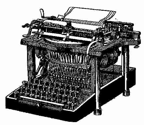
Fig. 228. Remington type-writer No. 7
With regard to the Remington, many changes of the details of construction, tending toward strength, durability, and a greater ease and convenience of operations, have been introduced into the machine, which have survived the severe test of time. This is especially the case with Remington No.7 (see Fig. 228). The most important of these valuable improvements are: An entirely new form of escapement, giving increased speed and an easy touch. The carriage is stronger and lighter, and steadier in all respects. The annoying rubber bands, which guide the paper around the platen have been discarded for a new form of paper guide, which may be adjusted to any desired point. The paper feed has been so arranged as to render it possible to write on wide or narrow paper, and this can be fed into the machine by a simple movement of the hand without lifting the carriage, and can be turned forward or backward at will. The ribbon movement is improved and works entirely automatically, reversing and giving a lateral movement. The marginal stops also are improved, and simple means provided for writing outside the margin whenever desired. There is a keyboard lock, locking the types at the end of the line, and thus preventing one letter being printed over another. A new variable line spacer is embodied, which makes it easier to write at any point on the paper, and prolongs the life of the platen for the reason that the type no longer strikes in unchanging grooves. An adjustable side guide for arranging the paper to any desired marginal indentation is a recent addition. A new two colour ribbon lever bearing a disc, which signals the color which the machine is adjusted to write is another recent addition.
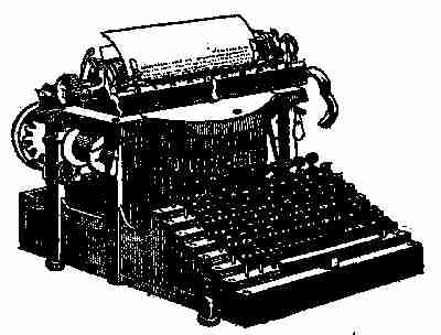
Fig. 229. Smith Premier No. 4
The Smith-Premier type (Fig. 229) has six models in the market and all nearly alike in their mechanism, differing only in the carriage arrangements, or the number of the characters. The machine is particularly simple in construction, and claims, by means of a very long and strong adjustable bearing, to have secured a perfect and permanent alignment. The type bars work on hardened steel bearings, 15⁄8 inches apart, and the type bars are the shortest of any on a "complete" keyboard machine. But the original and exclusive feature of the machine is the rocking shaft, which replaces the usual wooden or metal key lever. This consists of a circular rod, passing from the front to the rear of the machine—one rod for each key. Projecting from each shaft is a small bar, which is attached at the front end to the lower portion of the key stem. A similar projection is attached to the rod communicating with the type bar, and the result is that on the depression of the key the rocking shaft is made to revolve slightly, and so raise the free end of the type bar to the printing point. The type bar hangers are solidly riveted to the type ring. It will be seen that matters are so arranged that the amount of force to imprint the character is precisely the same in every case—a uniform, light and elastic touch. A very noticeable feature is its quietness in operation, due to the rigidity of its parts, and the fact that the ball-bearing principle is adopted wherever it can be used to advantage. It is also equipped with a circular brush, built into the machine, into which a handle can be immediately inserted, when, with a turn or two, the whole of the type can be cleaned.
The most striking recent development is the adoption of a three-coloured ribbon device. A simple movement of the lever in front of the machine brings the required colour into place ready for use. A two-colour or single colour ribbon may be employed. If desired the ribbon can be instantly shifted from the printing point for duplicating purposes. The ribbon reverses automatically, and it is attached to the spools with clamps—one on each spool, dispensing entirely with pins and tapes.
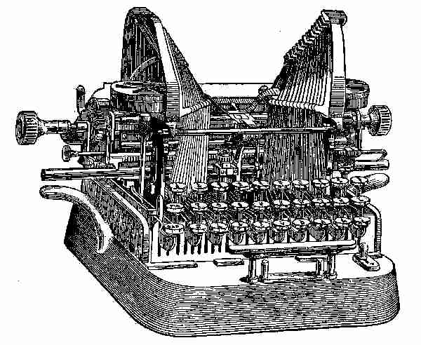
Fig. 230. The Oliver No. 3
The Oliver, Fig. 230, differs in mechanical principle from other machines. It has a wide U-shaped steel type bar, provided with a tool-steel axle as broad as the bar is long, and braced joints insuring the alignment without guides. The connection between the type bars and the key levers is direct and perpendicular. The type bars strike down on the platen in a line perpendicular to its plane, thus transmitting the maximum power with the minimum resistance, and further, maintaining the alignment with several sheets as with one. The type are of steel, and lie face upward—very convenient for cleaning. The keyboard is the "Universal," having twenty-eight keys with a "double" shift, giving eighty-four characters and the special model thirty-two keys, giving ninety-six characters.
The tension and depression of the keys are light and uniform. It may also be noted that the type blocks decrease in weight with the increase of length of type bar—necessary to secure a uniform stroke. The escapement mechanism is exceedingly simple and positive, and although very rapid is almost frictionless. The writing is semi-visible. The carriage is provided with three paper-feed rolls, thus ensuring a perfect feed of the paper down to the bottom edge of the sheet. It runs on anti-friction travellers on guide rails, ensuring an easy and steady motion. It is equipped with all the necessary devices. The line space mechanism operates automatically as the carriage is returned from the left to the right for a new line. The machine is compact and portable—weight about twenty pounds.
The parts of any of the machines now in the market, may readily be disconnected, but care must be taken by the novice in laying aside the parts so that they may be easily and correctly assembled. Repairs on the various parts may be made while out, and when made may be placed in situ. Any or all of the parts may be cleaned when the carriage is taken off. A little study of the machine when sitting before a person, will enable him to understand its mechanism, and when this is accomplished, cleaning and repairing can be done intelligently.
The tendency of the times is to employ the type-writer whenever possible. Special devices are from time to time invented to meet extended uses. The most important of recent applications is to office work for billing and book-keeping; this work alone has necessitated important modifications. In this direction, the tabulator calls for review. The lack of a practical method enabling tabular matter to be typed with a rapidity equal to that of the ordinary typing has long been felt to be a deficiency in type-writers. The invention of the tabulator has enormously increased the scope of the machine in this direction.
The tabulator is a device by means of which, figures or words can be written in columns, with out employment of the space bar or carriage release lever, or any adjustment whatever of the carriage by hand. By its use, the carriage may be set automatically at any point that may be required. At present this device is an accessory to most machines, but in the near future, it must form an integral part of all machines, and further, enable the carriage to be automatically placed in a proper position to write numbers in correct relation to each other in columns; that is, units under units, tens under tens, and so on. The built-in tabulators of to-day, with but two exceptions, are deficient in this respect. The tabulator in either form does not interfere with the use of the machine for other work, such as correspondence, etc.
The tabulator was followed by the introduction of a bi-chrome (two-coloured ribbon), and quite recently the Smith Premier Typewriter Company has advanced still further in this direction by introducing a tri-chrome (three-colour) ribbon. By a simple movement it is possible to vary the colour of the impression instantaneously, so that credits, marginal notes, footnotes, and underscoring may be indicated in red or other colour preferred. One-colour ribbons can be used if desired.
The machine embodying the parti-coloured ribbons and tabulator devices are generally known as "invoicing" machines, and by simple arrangements, every phase—not only of correspondence, but also of office and statistical work—can be accomplished, with an enormous saving of time. Items can be made on sheets, which may be taken from the machine with absolute certainty that when re-inserted, the subsequent entries will fall into their proper places.
Card Indexing.—For greater convenience in card indexing, special platens are obtainable, or the ordinary platens can be temporarily fitted with a metal clip. Both can be fitted to or removed from the machine in a few seconds, and the cards can be adjusted in an instant. The increasing use of the card file system for a wide variety of purposes lends special importance to the value of the type-writer for this class of work.
Interchangeable Carriages.—For years the thousand and one wide forms, statements, and blanks common in every business office, have been filled by the pen, the reason being that there was no machine practicable for both wide and ordinary work. The manufacturers of most of the modern type-writers now have models embodying interchangeable carriages, which enable any one possessing a machine with this improvement to have at the same time a set of carriages from the largest to the smallest, all of which can be used upon one machine. In one or two makes this is additional to interchangeable platens.
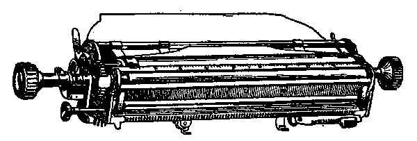
Fig. 231. Interchangeable carriage
Duplicators.—The value of a mechanical contrivance for the rapid and effective multiplication of copies of documents is fully recognized at the present time.
Duplicating machines have been on the market for several years. They will produce from one typescript original up to 3,000 copies, of any size, from a post card to a sheet of brief, every copy having the exact appearance of an original. While there are various makes and styles of duplicators, the main principle is the same throughout. The original is prepared by the now well-known stencil process; that is, writing the matter required with a type-writer on a sheet of waxed paper. The pressure of the type expels the wax out of the paper and leaves openings through which the ink can penetrate. In the Roneo rotary duplicator, a metal frame supports a cylinder of thin, perforated steel. On the outer surface of the cylinder is stretched a linen ink-pad, and over this is placed the stencil. The pad is inked by a rubber roller resting in an ink receptacle suspended between the two sides of the framework. By means of a simple lever this roller can be brought into contact with the cylinder, and ink is thus supplied as required. The cylinder is rotated by a handle. Paper fed into the machine is gripped by a rubber impression roller, which presses it against the stencil as the cylinder revolves, and the sheet perfectly printed, is then automatically discharged on the other side. The rotary can be fitted with three devices, namely a feeder, a simple contrivance, which automatically feeds the sheet into the machine, reducing hand labour to a minimum; an interlever, which automatically drops an interleaving sheet as each copy is printed—thus permitting of the use of highly glazed or very hard paper; a cyclometer for registering the number of copies. The rotary system is far superior to the hand duplicators in the matter of speed; such a machine will print ten copies while the hand device prints one. There is no lost motion, a copy being printed and discharged at every revolution.
Press Copying.—At the present time, there are four methods of letter copying in vogue, namely: (1) The letter-book method, damping sheets and screw press. (2) Roller process, water bath and drying drum. (3) Carbon paper. (4) The chemical letter copier.
The roller copies employ a water bath, and give but little if any improvement in the regulation of the degree of moisture. The copies are wound on a drying drum to prevent off-setting, and subsequently have to be cut apart for filing purposes.
The carbon process enables the answers to be filed with the original letter.
The modern chemical letter copier offers distinct advantages over other methods. It consists of a simple machine designed to carry a roll of specially prepared paper. The letter to be copied is laid on the feed board, the handle is turned, the sheet is fed automatically into the machine.
It will be noticed that a water bath and brush or damping sheets, are completely dispensed with; there is no "off-sheeting" and no drying drum. The copy may be either filed with the letter to which it relates, or placed, day by day, in a cover having the appearance of an ordinary letter-book; or two copies can be made of each letter—one for filing and the other for the book.
(1). A type-writer should be durable. Every part should be simple and strong and adapted to serve its purpose with the smallest degree of wear. Every mechanical movement must be definite, and incapable of incomplete performance. All wearing parts should be adjustable and interchangeable.
(2). It should possess absolutely "visible" writing. The common-sense way to write easily and speedily is to see what you are writing while you are writing it.
The writing should be performed in such a part of the machine as to be most readily seen during progress.
(3). The keyboard—on type bar machines in particular—should be that known as the "Universal," or "Standard" arrangement.
The keys on any style of keyboard should have a light and uniform depression, so that the machine may be operated with the minimum of fatigue.
(4). The types should present an even and regular appearance, termed "alignment." A type bar made of suitable material in the right way is the keystone of typewriter construction. In all machinery, there is some part on which falls the greatest strain and wear; consequently on the durability of that part rests the life of the machine. The devices used to secure alignment are numerous and ingenious. One machine depends on a wide pivoted bearing and a rigid type bar; another has a bearing composed of a continuous steel rod, with a type bar flexible while in motion, and made rigid at the printing point by means of guides; a third employs a wide pivotal bearing, a flexible type bar and an indispensable guide plate at the printing point; a fourth employs a compound type bar and an indispensable guide at the printing centre, and so on. Some have wide and adjustable bearings, to enable the wear to be taken up. These devices, however, are not the only essentials. The type bar hangers in machines embodying the pivotal principle need to be rigid and solidly fixed, while the paper carriage should be perfectly rigid and present a level and even platen surface for the type to strike against.
(5). The type should be capable of being easily and quickly cleaned, and in such a way as not to injure the type or soil the hands. A device should be embodied for rendering it impossible to batter the face of the type when the type bars are accidentally struck one against the other, and for preventing the type perforating or puncturing the platen.
(6). The mechanism controlling the movement of the carriage should act rapidly and uniformly, and its tension should be adjustable. The carriage should have a sure and regular paper feed and be capable of accommodating any smaller width of paper; also the margin regulators and bell trip should be easily and readily altered.
(7). The platen roll should be instantly interchangeable, thereby allowing of a soft substance platen being used for a single copy work and a hard one for manifolding. If the hard platen is of reduced diameter, more perfect alignment is secured on machines employing a complete circle of rigid type bars and a central top carriage.
(8). The line-spacing mechanism should be variable, and effected by one movement at all times; that is, the same movement that accomplishes the line feed should be utilized to return the carriage for a new line.
(9). The ribbon movement should consist of a reliable feeding mechanism, and allow of the fabric being quickly withdrawn, replaced, or adjusted. It should bring the whole surface in contact with the type, and also automatically reverse the endwise travel.
(10). The machine should be as noiseless in operation as possible. Machines differ very much in this particular. The employment of the guides to force the alignment introduces metallic contact, and consequent friction and noise.
COPYRIGHTS
Directions for Securing Copyrights, under the revised act of Congress, which took effect August 1, 1874.
(1). A printed copy of the title of the book, map, chart, dramatic or musical composition, engraving, cut, print, photograph, or a description of the painting, drawing, chromo, statue, statuary, or model or design for a work of the fine arts, for which copyright is desired, must be sent by mail or otherwise, prepaid, addressed: Librarian of Congress, Washington, D. C.
This must be done before publication of the book or other article. No entry can be made of a written title.
(2). A fee of fifty cents, for recording the title of each book or other article, must be enclosed with the title as above, and fifty cents in addition (or one dollar in all), for each certificate of copyright under seal of the Librarian of Congress, which will be transmitted by early mail.
(3). Within ten days after publication of each book or other article, two complete copies of the best edition issued must be sent, to perfect the copyright, with the address Librarian of Congress, Washington, D. C.
The postage must be prepaid, or else the publication enclosed in parcels covered by printed Penalty Labels, furnished by the Librarian, in which case they will come free by mail, according to rulings of the Postoffice Department. Without the deposit of copies above required the copyright is void, and a penalty of $25 is incurred. No copy is required to be deposited elsewhere.
(4). No copyright is valid unless notice is given by inserting in every copy published, on the title page or the page following, if it be a book; or if a map, chart, musical composition, print, cut, engraving, photograph, painting, drawing, chromo, statue, statuary, or model or design intended to be perfected as a work of the fine arts, by inscribing upon some portion thereof, or on the substance on which the same is mounted, the following words, viz: "Entered according to act of Congress, in the year——by——, in the office of the Librarian of Congress, at Washington," or, at the option of the person entering the copyright, the words: "Copyright, 19—, by——."
The law imposes a penalty of $100 upon any person, who has not obtained copyright, who shall insert the notice "Entered according to act of Congress," or "Copyright," etc., or words of the same import, in or upon any book or other article.
(5). Any author may reserve the right to translate or to dramatize his own work. In this case, notice should be given by printing the words "Right of translation reserved," or "All rights reserved," below the notice of copyright entry, and notifying the Librarian of Congress of such reservation, to be entered upon the record.
(6). Each copyright secures the exclusive right of publishing the book or article entered for the term of twenty-eight years. Within six months before the end of that time, the author or designer, or his widow or children, may secure a renewal for the further term of fourteen years, making forty-two years in all. Application for renewal must be accompanied by explicit statement of ownership, in the case of the author, or of relationship, in the case of heirs, and must state definitely the date and place of entry of the original copyright.
(7). The time within which any work entered for copyright may be issued from the press is not limited by any law or regulation, but depends upon the discretion of the proprietor. A copyright may be secured for a projected work as well as for a completed one.
(8). A copyright is assignable in law by any instrument of writing, but such assignment must be recorded in the office of the Librarian of Congress within sixty days from its date. The fee for this record and certificate is one dollar, and for a certified copy of any record of assignment one dollar.
(9). A copy of the record (or duplicate certificate) of any copyright entry will be furnished, under seal, at the rate of fifty cents each.
(10). In the case of books published in more than one volume, or of periodicals published in numbers, or of engravings, photographs, or other articles published with variations, a copyright is to be entered for each volume or part of a book, or number of periodical, or variety, as to style, title, or inscription, of any other article.
(11). To secure a copyright for a painting, statue, or model or design intended to be perfected as a work of fine arts, so as to prevent infringement by copying, engraving, or vending such design, a definite description must accompany the application for copyright, and a photograph of the same, at least as large as "cabinet size," should be mailed to the Librarian of Congress within ten days from the completion of the work or design.
(12). Copyrights cannot be granted upon Trade-marks, nor upon Labels intended to be used with any article of manufacture. If protection for such prints or labels is desired, application must be made to the Patent Office, where they are registered at a fee of $6 for labels and $25 for trade-marks.
(13). Every applicant for a copyright must state distinctly the name and residence of the claimant, and whether the right is claimed as author, designer, or proprietor. No affidavit or formal application is required.
Office of the Librarian of Congress.