PART I (continued 3)
Reading edition
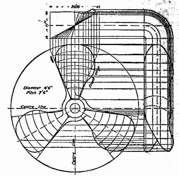
Fig. 42. Propeller lines complete
Lay out the propeller, as shown in Fig. 42, which will give the elevation of the blades, all being alike.
To find the area of a propeller blade, mark it off in parallel lines, say 3 in. apart, and note the width at the centre of each portion. Add the widths together, and divide by the number of widths. This will give the mean width, which must then be multiplied by the length of blade to obtain the area. If the measurements are all in inches, the result should be divided by 144 to give the area in square feet, and then be multiplied by the number of blades to give the total area.
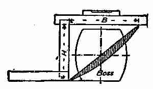
Fig. 43. Angle of propeller blade
To measure the pitch of a propeller, lay it down on a level surface, hold a straight edge level across centre of blade with a square up from the lower edge, as in Fig. 43. Measure the distance B and H and the radius R from the centre to the part where the measurement is taken; then B : 2wR :: H to pitch, P or P = 2wRH/B. The measurements may be made in more than one place and the average taken, as the blades are sometimes twisted slightly.
Scaling only from the drawing, P = 2wRH/B 2 × 3.1416 × 1.6 × 1/1.27 = 7.74, say 7 ft. 9 in. pitch, whereas the intended pitch was 7 ft. 6 in.
A good illustration of the use of the screw may be seen in the carpenter's auger, used for making or boring holes in wood. These tools are provided with a small tapered screw on their points, and this is followed by cutting edges and a larger spiral. The larger spiral is for the purpose of drawing up the chips or shavings. Another tool is made having two blades attached to the bottom of an iron bar formed like the blades of a propeller, which is sometimes employed for boring or digging post holes in clayey or soft soil. The machine is turned by a cross handle on top, and is frequently drawn up to bring out the soil until the hole is deep enough. The ordinary wood screw is one of the most useful of contrivances for fastening wood together, and for attaching to surfaces, hardware, ornaments, or other materials. The adhesive strength of nails is already shown, and the adhesive strength of wood screws, according to Bevan, is set down as follows:
WOOD SCREWS
The following are the thicknesses or diameters corresponding to the list numbers. Other thicknesses can be interpolated, each size varying in succession 1⁄64 in.—
No.0001 5101418 22273240
Thicknesses in parts of inches 1⁄323⁄641⁄16 1⁄8 3⁄16 1⁄45⁄16 3⁄8 7⁄16 1⁄2 5⁄8
An ordinary 2-in. wood screw, driven through a 1⁄2-in. board into hard wood, was found to be 790 lbs., and a force of about 395 lbs. was required to extract it from soft wood.
When screws are hard to drive or screw in place, a long screw-driver should be used, as screw-drivers with long handles seem to have a much greater leverage than short handled ones in driving screws home. Screws, however, are often split at the head, if care is not taken when using a long driver.
If a screw is rusted, hard to move or withdraw, it can be loosened by applying a hot iron to the head and making it hot. The heat expands the screw and, of course, makes the hole larger, and when the screw cools it contracts a trifle so that it may be withdrawn quite easily.
VII AEROPLANES
George and Fred were so much interested in the Caroline that they neglected to do some work Mr. Gregg had suggested, but a hint or two from him reminded them that sailing the new boat every day would get so monotonous it would cease to be a pleasure. Fred, therefore, set to work to put the new property in apple-pie order, by cleaning up the grounds, burning the rubbish, and tidying the place generally. Nick, not being needed longer, was allowed to go, with the promise that whenever a man was required about the place, he would be chosen. His departure left all the work to Fred and George, both of whom gladly accepted the duty.
The first thing was to set up three or four long benches on the river bank. These were built exactly in the same manner as the seats alongside the tables. Three short posts were let into the ground for each seat, and a good, sound plank spiked solid to their tops. One of the seats was made four or five inches lower than those at the tables, so as to accommodate the smaller children. The two boys did the work well, though they found it a little hard to dig the holes in the ground and saw off the posts. George's hands became a little blistered and sore, but his mother soon cured them, though she warned him against working too hard or too long at a kind of labour to which he was not accustomed.
After tea was over, it being a fine, warm, spring evening, the whole family went down to the river's edge to sit on the new seats and enjoy the view. Noticing the current of the river, Jessie questioned her father about its going one way sometimes, and then turning in the other direction. Her father explained that it was the movement of the tide that made the water flow against the stream at times, and that when there was no tide, the current took its natural course. This explanation did not seem to satisfy Jessie, and she asked why there were any tides. So Mr. Gregg promised to explain all that was known about tides to her in the near future. "I wish you would," said George, "and tell us about kites, balloons, and flying machines."
"Oh, yes," said the father, "I'll try to do that to-morrow night."
"I'm glad, father," said Fred, "as I want to try and make a model for George before the Fourth if I can, so he can have one to fly across the river that day, instead of fooling with fire-crackers and other dangerous fireworks."
"That's a good idea, Fred," said the father. "A model aeroplane, decorated with silk flags would give a great deal more real pleasure than firing off all the fire crackers in the state. It would be quite easy, now you have a boat, for one of you to be on this side of the river, the other on the opposite side, and to keep a number of little machines going to and fro across the water."
George seemed delighted at the prospect. Walter Scott had also been stricken with the aeroplane fever, and was busy making models, though, as yet, he had not finished any. Both Fred and George were anxious to hear all their father had to say concerning these machines, as they knew he would be thorough, and make it all plain. Mr. Gregg told the boys that to explain fully the theory and practice of building an aeroplane of any kind would take some time, but he would willingly give it for their benefit, and would discuss the subject of aeronautics at length so as to give them some pointers about the design and practical making of flying machines.
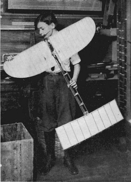
Copyright, 1911, by Underwood & Underwood, N. Y.
The Monoplane Model Complete "A Model Aeroplane, Decorated with Silk Flags Would Give a Great Deal More Pleasure Than Firing off All the Fire Crackers in the State"
On the following evening, Jessie did not forget to remind her father of his promise to tell them all about "air-ships and things," as she put it.
"All right, my dear," said Mr. Gregg, "I'll take you all into the 'lion's den' shortly after tea. But tell me, why is it you are so anxious to know all about 'air-ships and things'?"
"Oh! that's all right, papa; Fred is going to build a great big ship, as soon as he knows how, and he has promised to take me up to the clouds in it for a ride."
"Well, my dear, it will take some time to tell you all about these things but I will make an attempt. For ages man has wanted to fly, and the Greeks tell us of a mythical personage named Icarius, and another named Dædalus, who flew to the sun. There have been many attempts to fly, both with and without mechanical aid, but history gives us nothing definite on the subject until about the year 1785, when two Frenchmen, named Montgolfiers, built a balloon sixty feet high and forty-three feet in diameter, and filled it with heated air. Attached to the bottom was a light cage made of wicker-work, into which were placed a lamb, a duck, and a rooster. The balloon was cut from its moorings and rose to a height of over 1,400 feet so that these animals were the first that ever went up in a machine made by hands.
"The Montgolfiers attained considerable notoriety, and out of their experiments grew the present dirigible Zeppelin, which measures 446 feet in length, over 42 feet in diameter, and is capable of carrying eight able-bodied men a distance of over 900 miles. This great machine is charged with gas, and driven by four three-bladed propellers, which are run by two gas engines of 110 horse-power. This is simply a monster balloon, suspended in the air by 529 to 700 cubic feet of hydrogen, or coal gas, which is much lighter than ordinary air.
"It may be said there are four distinct kinds of flying machines, each unlike the other in construction and in principle. The first is the old-fashioned balloon which has an envelope or covering of some air-tight fabric, and is inflated with a light gas. To it is attached a framework of some kind called a Nacelle, that carries the aviator, the steering gear, and the necessary engines to operate the propeller or propellers.
"The second kind of flier is the aeroplane, which, as its name indicates, is supplied with 'air planes,' that give it the power of rising and falling at the will of the operator when the machine is in motion. These planes play a very important part in the successful operation of the machine, as I will explain later. The first type of machine is classed as a 'lighter-than-air' machine or a balloon, while the planes of all kinds are classed as 'heavier-than-air' machines. Among other types of 'fliers,' there is the helicoptere, which is raised by screws or propellers on vertical shafts. These revolve rapidly, and drive the machine upward, just as the propeller on the Caroline drives her forward when in rapid motion. Another type, nearly abandoned, is called the ornithoptere, or 'wing flyer.' These machines are built to operate like the wings of a bird, and are provided with the necessary contrivances to work the wings, both vertically and horizontally. This type, like the helicoptere, is not considered practicable, and is virtually abandoned, so that the field is now left altogether to the 'lighter-than-air,' and the aeroplane machines. I do not intend giving you any instruction regarding balloons, or dirigibles, as I think such is unnecessary, but will confine myself altogether to the discussion of aeroplanes.
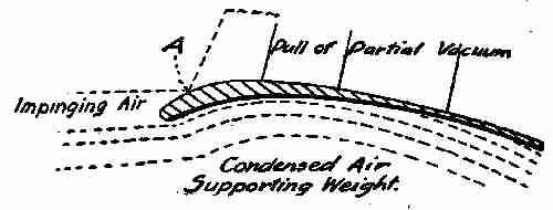
Fig. 44. Aero-curves
"It must not be supposed because of the name aeroplane, that the so-called plane is a real plane; it is not. The front edge of an air-ship plane must always be curved, as shown in Fig. 44, so that the air strikes the under surface and is forced under the plane, to buoy up the machine as it moves forward; or, to put it another way, there must be a current of air either natural or artificial on which the machine must float, or it will be drawn by gravitation to the earth. While we cannot see air or wind, we know from experience that it has great power, and for thousands of years ships have been propelled across the seas by this force, acting on sails of some kind. We know how difficult it is to travel against a high wind, and it is this quality in the air that makes it possible to travel through it. The resistance of the atmosphere makes it possible for the aviator to hold his machine suspended in opposition to the laws of gravity, and to drive it forward and upward by means of the revolving propeller acting against this resistance, the motor acting on the same principle and manner as the wheel or propeller of a boat when it is urged forward. If, as I have seen George do, we take a flat stone, a piece of slate, or flat metal, and throw it along the face of the river, in such a manner that its flat surface strikes the surface of the water, it will skim along, striking the water at intervals in its course, until the force given by the hand that threw it is exhausted, when it will drop and sink. The water, though lighter in equal bulk than the stone, is aided by the force given by the hand to buoy up the stone until the force is expended. The curve on the front edge of the planes, when the machine is in motion, really takes in more air than the space allowed for it under normal conditions, and it may be said to be compressed to some extent. If the wind be blowing in the 'teeth' of the machine, the resistance of the air will be greater, and the buoyancy of the machine increased. So, also, if the machine is travelling rapidly, the motion will increase the resistance and the buoyancy at the same time. The moment the propellers stop, gravitation grasps the machine, and if the planes are kept evenly balanced it will quietly and gently descend to the earth. You must particularly bear in mind that wind blowing in the face of a machine tends to hold it up, and that a machine flying rapidly makes its own wind, so that the results are the same.
"The curve on the front of the planes may be called an 'aero-curve,' and much of the success of the machine depends on this curvature of the planes, which gives to the inside of the plane a concave shape of a peculiar character, and to the outside a convex form.
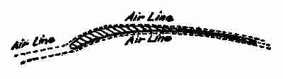
Fig. 44a. Maxim's aero-curve
"If you examine the rough drawing I made for you on the blackboard (Fig. 44) you will notice that the upper or convex curve is different from the under or concave one, and it is upon this difference in curvatures that many of the flying qualities of the machine depend. This little section showing the different curves is the one used by many of the successful aviators, though some prefer the form invented by Sir Hiram Maxim, shown in Fig. 44a, which does not differ very materially from the previous section shown. In all cases, however, the accepted plane is one of a curved vertical section in which the convex side is uppermost and the upper surface more curved than the lower. Although different authorities disagree as to why this shape of plane is best, all agree that it is so. Sir Hiram Maxim's theory is that the air follows both the upper and lower surfaces of the plane, as shown in Fig. 44a, while Phillips holds that the air follows the lower surface of the plane, and, striking the hump, shown at A, Fig. 44, is reflected off the upper surface of the plane, thus forming a partial vacuum on the upper surface, which gives an additional upward pull to the plane. There is, however, little doubt that most of the work is done by the force exerted on the lower surface of the plane.
"Another consideration that enters into the design of the plane is the aspect ratio, or the ratio between the depth of the plane fore and aft, and the width or span. Authorities do not agree about this latter consideration. A practical aspect ratio, one states, is 6 to 1, as, for instance, a plane 39 feet spread by 6 feet 6 inches in depth. In Santos Dumont's Demoiselle the aspect ratio is only 3 to 1. The ideal plane, however, would be a plane of great length and little depth, but this is impossible in the practical machine, as a plane of excessive length would greatly weaken the construction of the machine. Again, the different authorities do not agree as to the shape of the ends of the planes. Lanchester says that an efficient plane must be of rectangular form, and the Voisin and Curtiss planes are rectangular, whereas the wings of the Blériot and the Wright planes are decidedly curved at the tips.
"I will show in other illustrations the method of placing the planes on such machines, as made by Curtiss and some other noted aviators.
"I think I have said sufficient to give you a fair idea of the reason why an aeroplane can be made to navigate the air, but I have not told you how its direction can be controlled. No doubt, if the air were always still and not subject to change, there would be but little difficulty in controlling the direction of the machine, but, unfortunately, this is not the case, so provision has to be made to meet various changes as they occur. A downward current of air causes the plane to change its inclination to the horizontal, so that it will not support the weight, and the machine falls to the ground. To overcome this unsatisfactory state of things, small auxiliary planes are used to counteract the effect of varying air currents. They control the movements of the main planes so that they always bear the same inclination to the horizontal, and they are also used to elevate the machines so as to clear small obstacles. If any great increase in altitude is desired, the speed of the engine must be increased and the planes driven more rapidly through the air, thus giving them more lifting power.
"It may be that in a short time, additional balancing planes will not be necessary, as some other scheme may be invented that will regulate the balance of the aeroplane. Already an Australian inventor, called Roberts, has applied the gyroscope to the aeroplane in order to solve the problem of making it balance automatically. It exerts a balancing force equal to 300 pounds, placed 18 inches on either side of the centre of gravity. The gyroscope is driven by electricity, and controlled by a pendulum which swings right or left, according to the tilt of the aeroplane. Mr. Roberts is also working on a small aeroplane which is to be controlled by wireless telegraphy. His inventions are being tested by the British War Office. There are many other inventors on three continents busily employed in trying to solve the balance problem.
"A very important matter in the construction of the aeroplane is the position of the screw propeller. Sir Hiram Maxim advocates placing it at the rear of the planes, and this construction is carried out in the Wright, Curtiss, Voisin and Baldwin-McCurdy machines, while the tractor screw is used on the Blériot, Antoinette, and Roe fliers. Sir Hiram's theory is that if the screw is placed in front, the backwash strikes the machine, which offers a good deal of resistance to the passage of the air, and retards action; but if the propeller is placed in the rear, the resistance of the machine imparts a forward motion to the air with which it comes in contact, and the screw, running in air that is moving forward, has less slip, and is, therefore, more efficient than the tractor screw.
"While the construction of the aeroplane is yet in an experimental stage, it is progressing quite rapidly, and though no definite rules covering the whole ground of construction and management can yet be laid down, the following points may be well considered before any steps are taken in making or using any make of aeroplane: (1) That it is useless to construct the planes of flat vertical section, as much lift is lost in doing so, and they are best constructed after the manner shown in Figs. 44 and 44a. (2) That the most practical aspect ratio is about 6 to 1. (3) That the angle of incidence of the inclined planes ought to be somewhere between 1 in 10, and 1 in 20 (i. e., the angle by which they are inclined to the horizontal, the forward or entering edge of the plane of course being the higher). (4) That a reliable motor, one that is immune from involuntary stoppages, is absolutely essential to prevent accidents. (5) That automatic stability of the machine is the theory of aeronautics that all inventors should study most carefully.
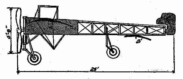
Fig. 45. Blériot monoplane
"The illustration I show here (Fig. 45) represents the monoplane in which the Frenchman, Blériot, crossed over the sea from France to England. The thick curved lines, shown at A, exhibit the main plane which gives the machine its name of "monoplane"—one plane—and B shows the rear auxiliary plane, which is also of curved section and curved ends. The plane A has an area of 150 square feet, and B has an area of 17 square feet, while the rudder C has an area of 41⁄2 square feet. The total length of the machine is 25 feet, the sweep of the rudder 6 feet 6 inches. The rudder is a plane, pure and simple, and may be constructed of any light material that is strong enough to stand a reasonable wind pressure. The planes must be covered on both sides with some light fabric, silk preferred, and all the framework made as light as possible, consistent with safety.
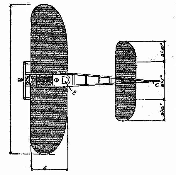
Fig. 46. Plan of Blériot machine
"The plan I show at Fig. 46 will give you a good idea of the form of this machine, if you were looking from above at it. E is the point where the aviator sits, and where the 30 horse-power engine is placed. The ends of the planes are rounded off, and the ends of the rear plane at DD, are made adjustable so that the machine may be made easier to manage when in motion.
"All engines used in aeroplanes are of the internal combustion type, made purposely for aerial flight, and are as strong and as light as it is possible to make them.
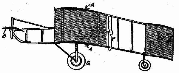
Fig. 47. Biplane
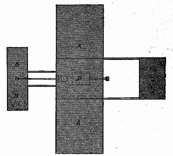
Fig. 48. Voisin biplane
"The biplane, or two plane machine, is fitted up on somewhat the same lines as the monoplane, having two planes one above the other, as I show you in Fig. 47. The dark portion A A, shows the positions and curvature of the planes. The plane B is called the elevator because it keeps up the head of the machine. C shows the tail with a single plane. D is the part containing the mechanism and the aviator's seat. E shows the vertical planes, made of some light fabric stretched over a bamboo frame. The propeller is shown at F, and it is about six feet in diameter. The two carrying wheels, shown at G G, are simply light bicycle wheels which tend to ease the landing of the machine when it comes to the earth. It will be seen that machines may differ in the style of construction and yet, so long as they contain the principles I have described, they will fly with more or less success. The illustration, (Fig. 48), shows the plan of the biplane, which is somewhat different in arrangement from the monoplane. This sketch is of the Voisin biplane and shows the tail-piece, something not used in machines of the Wright type. The Voisin machine is quite popular in Europe, particularly in France. It is not very difficult to construct or easy to control; at least, it has that reputation.
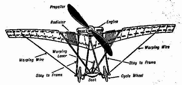
Fig. 49. The Santos-Dumont monoplane
"The Santos Dumont monoplane, Demoiselle, shown in Fig. 49, is said to be the smallest and lightest known practical machine, and there are no patents on it, the inventor having published sketches and drawings of all its details. Contrary to the usual plan, the aviator, in this machine, sits below the motor, so that the propeller blades cut across the line of sight; but as it revolves very rapidly the vision is not affected. The whole machine, when complete, weighs only about 250 pounds. Its length is about 20 feet and its total width over the planes 18 feet, and it is about 7 feet 6 inches high. It is quite easy to build, as the framework, or chassis, is fixed to a bent piece of ash or elm—like a sleigh runner—which answers very well, because when the machine begins to move the rear end rises first. If desired, the frame can be made so that the whole thing can be taken apart. Sockets, like those used on finishing rods, may be attached at the joints and junctions to hold the structure together. The two spars that constitute the main support of the planes are formed of ash, this having been found the best material for the purpose, as it is also for the making of the propeller blades. One of the spars should be fixed about nine inches from the front edge, and the other about twelve inches from the back. Bamboo cross pieces are fastened about nine or ten inches apart between the two main spars. All is covered with oiled silk, applied in two thicknesses. The area of the main plane is some 115 square feet, and that of the tail-piece about 50 square feet. To cover all this would require about 400 square feet of silk.
"I have heard it said that aeroplanes are hard to manage, difficult to drive, and extremely dangerous. This is not true entirely, but there is some truth in it. An amateur has to go through a 'course of sprouts' and must learn all about his machine before beginning to use it practically. Once he becomes master of it and can keep it well under control, he need not fear accidents, if he does not lose his head, nor venture out in half a gale. When we consider the number of experiments that have been made from time to time with imperfect machines, we find that fatal accidents have been very few, less, indeed, than the number recorded in the early stages of automobile history.
"I have been compelled to draw a number of the points I have given you from many sources, particularly from the writings of Messrs. Fetherstonhaugh and Lanchester, which does not detract from what I have told you, but rather guarantees its correctness.
"Well, children—it is getting late, but, before bidding you good-night, I think I should finish my talk on aeroplanes by showing you how to make a small model of a flying machine, if you are not too tired to listen further?"
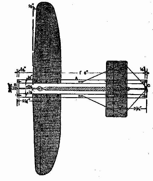
Fig. 50. A model aeroplane
"Please, father," said Fred, "do keep on." George, also, wanted to hear more, so Mr. Gregg decided to continue.
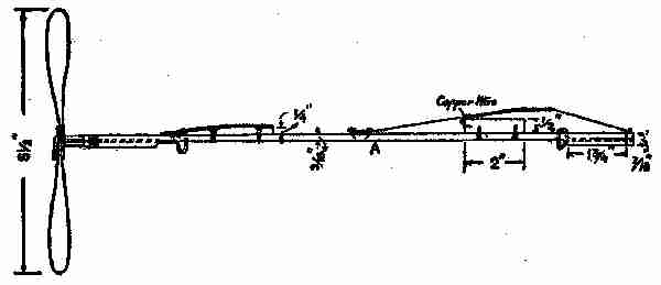
Fig. 51. Section model aeroplane
"I have given you an outline of the reason why an aeroplane can be made to rise from the ground and navigate the air; but I have not told you of all the kinds of machines that can be made to fly, for there are many others than those I have spoken of. One is the glider, which does not carry an engine, but, as its name indicates, glides along in the air at a distance not far from the earth. These are not capable of travelling very far and, therefore, are not likely to come into general use. They have to be started either by gliding off a high tower, by sliding down a hill or by being propelled by hand or towed by some rapidly moving machine. Some day, perhaps, a machine will be evolved on the same or similar lines as the glider, that can be propelled by natural forces, but the time is not yet. Beside the monoplane and the biplane, there is the triplane, constructed on the same lines as the other flying planes, that is to say, the three planes used on the machine are made the same as the planes on the others, each having a convex and concave side of different curvatures.
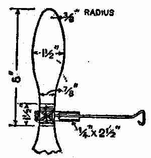
Fig. 52. Blade of propeller
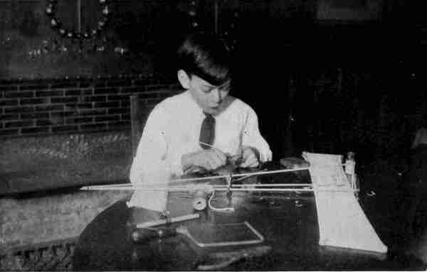
"The monoplane which I am about to describe and illustrate, and which I show in Figs. 50-51-52, can be easily and cheaply made, and can be guaranteed to fly, after a little experimenting to get the correct balance and angle of the planes. The frame A will first be treated. Get two pieces of yellow or white pine (the lightest and most easily procured wood), cut them to the shape shown, 1 foot 6 inches long, 1⁄2 inch by 13⁄16 inches in the middle, and thickened at the ends to take the screws from the end bars B and C (Fig. 50). Take great care to make them exactly alike. The end pieces B and C, which are 21⁄2 inches by 7⁄16 inch by 1⁄4 inch can then be screwed to the side pieces A, and a rectangular frame is the result. Should the screws split the wood in the slightest degree, new pieces must be made, as the plane is sure to get rough usage in falling on the ground a few times.
Photograph by Brown Brothers
Making an Aeroplane Model "If the Screws Split the Wood in the Slightest Degree, New Pieces Must be Made"
"The planes are also made of yellow pine. They must be exactly equal to one another in weight, one being right handed and the other left. The wood must not be more than 1⁄22 inch thick, and, if possible, even thinner. A large circular chip box will be the best thing from which to make these. Gum a piece of tracing cloth on top of the planes, and allow about 2 inches to overlap at the large ends, to twist and glue round the main frame when fixing. The cloth will fulfil two useful and necessary purposes. It will strengthen the planes and curve them to a very large extent. This curvature is essential to the flight of the machine. A wooden block curved to suit, and inclined at about 5 degrees, is fixed between the back planes and the frame.
"The front or small plane is 8 inches by 3 inches, and made in the same way as the others. It must be adjustable, and is, therefore, mounted on two wooden blocks, 2 inches by 1⁄4 inch by 1⁄2 inch and fastened by means of copper wire which acts as a hinge. Four silk cords are fixed to the movable end of the plane, two being fastened to nails at the rear end of the frame and two to the front, to hold the plane at any desired angle.
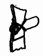
Fig. 53. Connections of propeller blade
"The propeller blades (Fig. 52) are made of thin aluminum. Two sheets are cut out the same size and shape, and placed with their ends overlapping (see Fig. 53). A piece of steel wire 1⁄16 inch in diameter is bent and placed between them to form the shaft. The whole is then fixed in a piece of light copper tube, which is slotted by means of a hack saw or fret saw to receive them. The blades are bound crosswise to the tube by means of thin wire or strong thread; then twisted to a pitch of about 6 inches. It is also advisable to place a washer between the copper tube and the end bar of the frame.
"This method of fixing the propeller blades is not the same as that shown in Fig. 50 but it is the better way.
"The drive for the propeller is elastic (a rubber band), which, when twisted and released, will rapidly revolve the shaft for a short time. The best kind to use is the gray variety, and when in the form of bands, say 3⁄8 inch by 1⁄16 inch by 6 inches, is ready for use without jointing. The wire carrying the elastic should be made so that the elastic is just in tension when untwisted.
"The monoplane, when complete, should be tested without the propeller until it will glide perfectly. The front of the plane will need weight added if there is a tendency to somersault; but if the back rises ahead of the forward end, more weight is necessary there. The best glide to be expected is about a 1 in 6 slope. The propeller should then be tried, and a flight of 50 or 100 feet, or more, should result. If there is a tendency to twist, owing to the side pull of the propeller, a screw should be fixed to the end of the plane to counteract it.
"A much longer flight can be given the model, if the spring is made so that the tension may continue a longer period. Sometimes a rubber attachment can be applied and twisted so that the propeller can be kept running long enough to carry the machine a much greater distance than here stated. The dimensions of all the parts of the machine are marked on the illustrations, so that you will find no difficulty whatever in making a model monoplane that will fly from the start. In the making of little models of this kind, you will encounter many things that will tax your skill and ingenuity, as amateur workmen.
"Now, children, I have told you all about aeroplanes that I intended, though I may take up the subject again, when I try to explain the recognized theory of flight, and the making and flying of kites."
VIII KITES, SUNDIALS, PATENTS
The next day, just as Mr. Gregg returned from his office, Fred, Jessie, and George landed on their new dock from the Caroline. They had been for a sail on the river, and Jessie was quite enthusiastic over the trip. "Fred was a real good captain. Why, papa, he let me steer the boat all by myself, and taught me so well I didn't have any collisions."
An hour or so later the boys, Jessie, and Mr. Gregg, retired to the den.
After questioning the boys regarding the previous talk, to discover if they remembered the main points, Mr. Gregg said he would now tell them something of kites and kite flying.
"The highest kite ascent yet recorded was made at the aeronautical observatory at Lindenburg, (Prussia) on November 25, 1905, 21,100 feet being attained. Six kites were attached to one another with a wire line of nearly 16,000 yards in length. The minimum temperature recorded was 13 degrees, F.; at starting the reading was 41 degrees. The wind velocity at the surface of the earth was eighteen miles an hour, and the maximum altitude it reached was fifty-six miles an hour. The previous height record by a kite was nearly 1,100 feet lower, and it had been reached from a Danish gunboat in the Baltic. These ascents were wonderful, for it is not an easy matter to train a kite higher than a given altitude, for several reasons. The higher a kite rises the more string it will require, and this tends to weight down the plane or kite.
The wind, too, acting on the string, tends to retard the upward flight and to cut short further ascent. When an ordinary kite reaches a height of 1,200 or 1,500 feet, it is doing very well; and few exceed this height. When Benjamin Franklin angled in the clouds for lightning, his kite did not attain an altitude of more than 1,000 feet, which was quite sufficient for the purpose he had in view. When Franklin flew his kite, he was so afraid of ridicule that he took a small boy with him to carry the kite and string, in order to prevent his neighbours from thinking he was going 'kite flying.' In these days when a man is seen flying a kite, people very naturally imagine him to be an aeronaut, studying the science for the purpose of improving or inventing a flying machine of some kind—for which there seems to be ample room.
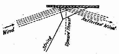
Fig. 54. Science of kite-flying
"The first thing a beginner in the science of aeronautics will want to know is, 'Why does the kite or machine lift itself off the ground?' If you take a kite and hold it in an inclined position, the wind on the lower side will have a tendency to blow it backward; but as it is held by the kite string, this movement is impossible, and so it is inclined to rise in the air (see Fig. 54). If we construct a large plane and equip it with a motor operating a screw which pushes or pulls the plane along through the air, the result is the same as if the plane were anchored, and the wind hits the lower surface of the inclined plane, thus forcing it up. Also, we find, within certain limits, the more you incline a plane the more lift or upward thrust will it give; but it will take more power to drive it through the air, and the faster the plane is driven through the air the less surface is required to support the weight. A matter of great importance in the construction is the shape of the plane, and the shape of the vertical section through the same. The shape of these planes has been explained in Figs. 43 and 44, and the reasons were given why these shapes were considered the proper ones for the purpose.
"It does not follow," said Mr. Gregg, "that all kites should have the same kind of a surface or plane, though the flat planes of the toys of our school days were all of the flat surface kind; these being of various shapes and sizes from the lozenge to the square, bow top, octagon, and many others, according to the whim or skill of the maker. One of the conditions of these planes or flat kites, was that each one must have at least one tail attached to the bottom of it. This tail was flexible, simply a piece of string having paper similar to 'curl papers' tied to it at intervals. The tail was a necessity, for without it the equipoise would be impossible. In China and Japan, where the natives have been kite-flying for more than twenty centuries, they make kites that fly and maintain the aerial equipoise without having tails hung to them, no matter whether the shape be that of a dragon, a lion, or an eagle.
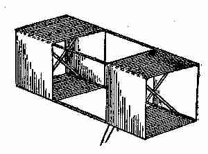
Fig. 55. Box kite
"A kite is simply an aeroplane on a small scale, and should be considered as such, as it has a fixed fulcrum in the belly band, a constant pressure when flying, and an angle which is varied in proportion to the load it may have to carry. The common kite is easily made, but it does not always fly as desired; for it seems almost impossible to make two kites that will fly in the same manner under similar conditions. Box kites are the most reliable, and not so very difficult to make, as you will discover by examining Figs. 55, 56, and 57 and following the directions I give you. First, procure four straight strips of light wood, preferably spruce, 2 ft. 6 in. by 3⁄8 in. by 1⁄8 in.; these dimensions should be full (see Fig. 55.) Obtain also four other pieces, each 1 ft. 71⁄2 in. long, but 1⁄16 in. wider and thicker than the foregoing, and halve their ends to a depth of 1⁄8 in. by 1⁄4 in., in order that when the false end A (Fig. 56) is tightly bound on, these cross sticks will firmly grip the long pieces edgewise, the sides of the cells being indicated by the dotted lines. The long sticks should be notched at a distance of 4 in. from their ends to receive the forks of the cross sticks.
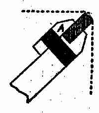
Fig. 56. Making a kite
"The width of the cloth or paper cells should be 8 in., and they should be separated by a distance of 1 ft. 1 in. or 1 ft. 2 in., their edges being bound with fine twine. The easiest way to make the cells is to cut two strips of the material, 10 in. wide and 4 ft. 81⁄2 in. long. Turn over the edges 1⁄2 in. along each side, and insert fine strong twine! If paper is used, glue the fold; if cloth, stitch the hem. When completed, either glue or stitch the ends of the strip with a 3⁄4 in. lap, so as to form a continuous band. By folding, divide this accurately into four equal parts and at each of the creases glue one of the long sticks edgewise (see Fig. 56). When dry, the whole can be put together and the flying line attached, without a bridle, as in Fig. 55. For additional clearness an enlarged detail of one end of the kite is shown at Fig. 57.
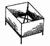
Fig. 57. Single box kite
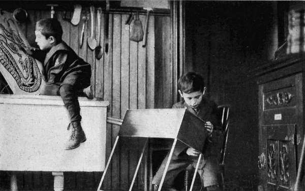
Photograph by Brown Bros
Making Kites "Box Kites Are the Most Reliable, And Not so Very Difficult to Make"
"It is advisable in all cases to make the cross pieces a trifle too long, to insure their straining the band tightly. They may also be shortened by cutting away the shoulder formed by the halving.
"These kites are easy to fly. Avoid an enclosed space, where the wind whirls in invisible eddies; having let out 20 yds. or 30 yds. of line, get some one to throw up the kite in the usual fashion. If several large kites are sent up in tandem, steel wire should be used.
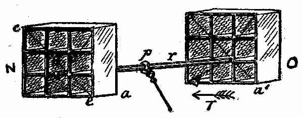
Fig. 58. Square cellular kite
"Another kind of a kite, known as the cellular kite is shown in Fig. 58. This is made by forming two square frames N. O., divided into nine compartments each and connected together by a light rod at r, the fulcrum or string being at P, the air pressure at T. The whole forms a good, strong kite, but it is not able to carry much weight, on account of the equipoise being self adjusted in accordance with the constant pressure and surface. The equipoise is due to the current being cut by the edges a a´, and diverted into the cellular divisions of each area. This being the case, any upward or downward tendency of a a´, would be counterbalanced by the effect on the other side and the kite would naturally adjust itself on the opposite side. We are not dependent upon any particular shape for obtaining a good serviceable kite—like the plane made kite, the cellular one may be of any shape. I show you one here, at Fig. 59, having a circular rim, with thin tubes inserted in such a manner that the current of wind will rush through when the machine is in the air. The two portions, A and B, are held together by a rod in a similar manner to the square kites, and the cord or fulcrum is fastened to the rod at R.
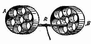
Fig. 59. Circular cellular kite
"A number of kites may be sent up at once, all attached to the same string, if properly adjusted. Here are six square cellular kites looped together, shown at Fig. 60. They may be made of any suitable size, but need not be all of one size, though each pair would be better if made the same size. They may be looped up, as shown, and the point S may be loaded lightly; it will help to steady the kite and keep it from swaying.
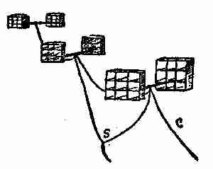
Fig. 60. Group of kites
"A peculiar kite, called 'a war kite,' is very popular in some parts of Europe, and in some parts of our country also. It is easily made and gives good results. It is on the principle of the 'cellular' or 'box' kite, being cubical or box-shaped, and, when used for carrying weights, usually has several cells built together, or several kites may be coupled when a heavy load, such as that of a man, is to be raised. These kites are made of light wood or cane covered with nainsook or fine cotton, and strengthened with cross pieces which hold the frames tight and keep the kite in shape. They can be taken to pieces and the covering material rolled up so that they occupy very little space. Two forms of box kites are shown in Figs. 61 and 62, and it will be seen that an attachment is made each side of the frame. This is fine steel wire, very light compared with its strength, wound on a drum by means of a small engine. Large kites of the ordinary form can be used for the same purpose, but their lifting power is not equal to that of the box kite. A small box kite is used for taking photographs, a camera being carried by a separate wire connection to the attachment wire, and the shutter released at the proper time by an ingenious arrangement, similar to the pieces of paper called 'messengers' which boys used to send up on the cords of ordinary kites. This kite is a little more expensive to make than most of those shown, but it gives an excellent result when properly handled.
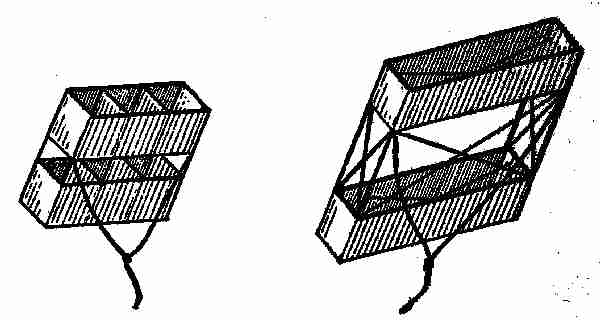
Fig. 61. Sextuple kite Fig. 62. War kite
"In making kites of any kind, the lightest materials consistent with sufficient strength, should be employed. The frames should be split bamboo or cane. The joints may be lashed together with fine wire or silk thread, and the envelope in each case should be fine silk or similar material that would be close, light, and strong. These qualities, in all sorts of kites and aeroplanes, are absolutely essential to accomplish the best results.
"Before leaving the subject of aeronautics, I think it would not be amiss to tell you something of bird flight. There are different modes of flying, just as men have different gaits in walking or running.
"Rapid wing movement does not always imply speed in flight, any more than does rapid leg movement imply speed in walking or running. With us it is the length of the stride that tells ultimately. What tells, correspondingly, in the flight of the bird is not known.
"Speaking broadly, long-winged birds are strong and swift fliers; short-winged birds are feeble in flight. When we consider that a cumbrous, slow-moving bird like the heron moves its wings twice per second when in flight, it is evident that many birds have a very rapid wing movement. Most small birds have it, combined with feeble powers of flight. The common wren and the chipping sparrow, for instance, have a flight like that of a young bird.
"What can give one more exquisite pleasure than to watch seagulls swooping round the edge of a cliff, to see them drift down wind with wings motionless, then suddenly dart downward, turn to meet the breeze, and beat up against it with all their ingenuity and skill?
"The beauty of a ship depends on the way it glides through the water. Watch a liner, and you can see that it is being driven by its screws, but look at a racing yacht: there is no sense of effort whatever. She seems to move like a bird, by natural means.
"Here is the secret of the beauty of the aeroplane. It seems to be completely master of the element in which it moves. It flies with no visible effort and at a little distance one could imagine it endowed with magic power, moving by natural force, like a bird.
"All the early attempts at flying were made on the theory of wing motion, and the failures resulting were doubtless due to careless study of what nature could teach. There was a great deal more to be learned from nature than from mathematics. An examination of the different types of birds testifies, among other things, to their rigid backs, and to the fact that nearly all their bones are hollow and have air cavities. An erroneous deduction had been drawn from this that the hollows were purely for the sake of lightness, and that the cavities were for hot air to make the bird light when it wanted to fly. The amount of lightness so obtained, however, was so small as not to be worth consideration. The passages are simply reservoirs for air, and they allow the bird more energy than a less freely breathing animal. The wing of the bird does a double duty: it is an aeroplane and a propeller combined. The valvular action has nothing at all to do with the flight. Some explanation of how a sparrow can rise from the gutter to the eaves may be seen by the difference in the construction of its wings from those of the swallow, which cannot rise from the ground like a sparrow, but has to get initial velocity. The swallow, however, has much more mastery over its movements in the air than the sparrow has. These, and many other things in connection with bird flight, under proper methods of scientific investigation, may show us the whole theory of aviation. I am inclined to think that scientific men will soon be able to solve the problem, and to give us better control of the coming aeroplanes, or even direct their flight by the aid of electric waves or other natural forces.
"In kite-flying, it is well to know something of the wind and its pressure, and, in this connection, the following short table will give some idea of the force exercised on objects in its path: A light air current presses 0.004 lbs. per square foot.
Light wind has a pressure of 0.125 lbs. per sq. foot
Light breeze 0.246 lbs. per sq. foot
Moderate breeze 0.406 lbs. per sq. foot
Strong breeze 2.00 lbs. per sq. foot
Moderate gale 2.98 lbs. per sq. foot
"This last should be the limit, as a kite or aeroplane of any kind will find it hard to manœuvre in a breeze stronger than a moderate gale. Of course, there are winds sometimes that have a velocity of 60 to 75 miles an hour, and a pressure of over 40 pounds to the square foot, but these would prove disastrous to any kind of a flying machine, if it was in action."
"Father," asked Fred, "how can one tell the velocity of the wind, without one of those expensive machines I see at the weather office, an anemometer, I think it is called?"
"I am glad," said the father, "that you have noticed those and other instruments for gauging and foretelling weather conditions. It is an indication that you keep your eyes open when you visit such places, and to learn by observation is almost as effectual as to obtain knowledge by experience. I have in mind a very simple contrivance you can make yourself, for measuring wind pressure from a couple of ounces to four pounds to the foot. I will make a sketch of it, which I am sure you will understand.
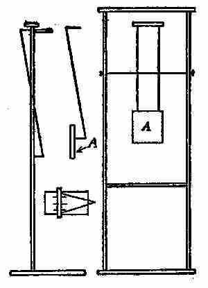
Fig. 63. Wind gauge
"It consists of a light pine or cedar wood frame on a strong stand, supporting on a centre two bent wires, carrying at one end a 3-in. square of thin wood, A, and on the other a thin bar of wood, to the centre of which is attached a fine string tied to a spring balance scaled to 1⁄8 of an ounce and up to 4 ounces (Fig 63). As the square of 3 inches is the 16th of a foot, each ounce on the spring is equal to 1 lb. pressure on the square foot. The latter balance slides in the V-frame at the back so as always to keep the square parallel to the face of the frame, whether the wind is strong or light, and the balance must be slidden in or out until the face of the square is so placed before registering the force of the wind. By attention to this it will register very truly up to 4 lbs., which is the extent of an ordinary spring balance. There is also a front view, a side view, and a bird's-eye view, also one of the bent wires and the 3-inch square. I think this requires no further explanation."
Fred was satisfied with the description of the register and promised to make one at an early date.
The following evening when they were all sitting on the river bank, Fred suddenly asked his father if it was difficult, or costly, to secure patents. He wanted to know, because he had been thinking of making a kite on a new principle—that of a funnel, and he was so sure it would prove a success that he would like to have it patented.
Mr. Gregg thought the scheme rather an ambitious one, but, while he could not see it as Fred did, he determined not to say anything that would be likely to discourage the boy. So he explained, as well as he could, the patent laws: "In order to apply for a patent it is necessary to file in the Patent Office at Washington, D. C., a petition, affidavit of invention, drawings, and specifications, all of which must be prepared in legal form and in accordance with official rules and practice of the office.
"This can best be done by a reliable attorney but an applicant should understand some of the requirements as well.
"The Patent Office does not require a model to be furnished in order to apply for a patent, but if the attorney is not near enough to see the one made by the inventor, then one should be sent him, unless good photographs and drawings can be supplied.
"Since the drawing attached to the specifications and claims is to be on a sheet of a special size, no attention need be paid to having the original sketches of a uniform size. When ready to apply for a patent, secure as much evidence as possible of the reliability of some attorney you have heard of and consult him about the matter, explaining as much as is necessary for him to prepare an outline that will suffice for a preliminary search through the records in the Patent Office to see that no interference will take place should the application be made.
"This usually costs $5.00, and an attorney often supplies copies of existing patents that look the most like the one in question.
"If it is thought that there will be no interference, the case is then prepared for the examiners, and the application duly made.
"The drawings should be made and lettered, so that the specifications can be written up, including the proper reference to the different parts.
"The drawings should be made upon paper stiff enough to stand in a portfolio, the surface of which must be calendered and smooth. The best kind is patent office bristol, though there is a style on the market printed with margin and headings all ready for use, but the surface is not of the best.
"The size of the sheet on which a drawing is made should be exactly 10 × 15 inches with margin lines one inch from all the edges, leaving a clear space of 8 × 13 inches.
"One of the smaller sides is regarded as its top, and measuring downward from the margin, or border line, a space of not less than 11⁄4 inches is to be left blank for the insertion of title, name, number and date, to be put in by the patent officials.
"All drawings must be made with the pen only, using the blackest India ink. Every line and letter, including the signature must be absolutely black.
This applies to all lines, however fine, to shading and to lines representing cut surfaces in sectional views. All lines must be clean, sharp, and solid, and they must not be too fine or crowded.
"Surface shading, when used, should be left very open. Sectional shading should be by oblique parallel lines, which may be about one-twentieth of an inch apart. Drawings should be made with the fewest lines possible consistent with clearness, for the drawings are subjected to photographic reduction, which decreases the space between the lines.
"Shading (except on special views) should be used only on convex and concave surfaces, and there sparingly, or it may be dispensed with if the drawing is otherwise well made.
"The plane on which a sectional view is taken should be indicated on the general view by a broken or dotted line.
"Heavy lines on the shade sides of objects should be used, except where they tend to thicken the work and obscure the reference letters.
"The light is always supposed to come from the upper left hand corner, at an angle of forty-five degrees.
"Imitations of wood or surface graining should not be attempted.
"The scale to which a drawing is made ought to be large enough to show the mechanism without crowding, and two or more sheets should be used if one does not give sufficient room to accomplish this end; but the number of sheets must never be increased unless it is absolutely necessary.
"Sometimes the invention, although constituting but a small part of a machine, has to be represented in connection with other and much larger parts. In a case of this kind, a general view on a small scale is recommended, with one or more of the invention itself on a much larger scale.
"Letters or figures may be used for reference, but they should be well made, and when at all possible should not be less than one eighth of an inch in height, that they may bear reduction to one twenty-fourth of an inch; or they may be much larger when there is sufficient space.
"Reference letters must be so placed in the close and complex parts of a drawing as not to interfere with a thorough understanding of the same, and to this end should rarely cross or mingle with the lines.
"The illustrations on pages of current topics under the head of new patents show the manner of putting in the reference lines from the letters to the part indicated.
"These are carried out some distance, but if placed on the face of the object where sectioned, a blank space should be left in the shading for the letter.
"If the same part of the invention appears in more than one view, it should always be represented by the same letter.
"Great care should be exercised in the matter of drawings, or they will be returned to the applicant, but, at his suggestion and cost, the officials will make the necessary corrections.
"The time required to procure an allowance of a patent averages from six weeks to two months.
"United States patents are granted for a term of seventeen years, and cannot be extended. The patent remains good whether the invention is worked or not, and no additional payments are required beyond the cost of first taking out the patent. Patents are not subject to taxation. Reissues of patents are granted whenever one is inoperative or invalid, by reason of a defective or insufficient specification, or by reason of the patentee claiming more than he had a right to claim as new, provided the error arose by inadvertence, accident, or mistake, without fraudulent intent. A fee of $30.50 must be forwarded upon application for patent.
"As stated before, a patent is obtained by a petition to the Commissioner of Patents accompanied by a description, including drawings and a model, when the invention will admit of these. A fee of $15 is required when the application is made, and a further fee of $20 when the patent is issued. Postage on model is at the rate of 1 cent per ounce.
"A patent for a design is granted to any person who has invented or produced any new and original design for the printing of woollen, silk, cotton, or other fabrics; any new and original impression, ornament, pattern-print, or picture to be printed, painted, cast, or otherwise placed on or worked into any article of manufacture; or any new, useful, and original shape or configuration of any article of manufacture, the same not being known or used by others before this invention or production thereof, or patented or described in any printed publication, upon payment of the duty required by law, and other required proceedings the same as in cases of inventions or discoveries. These are granted for three and one-half years, seven years or fourteen years, for which the respective fees of $10, $15, and $30 are paid the government.
"A caveat is a provisional protection to any person who has thought of an invention and desires the time to complete or perfect the same. It is procured at an expense of $10, and runs for one year with the permission of renewal from year to year.
"In Canada the patent office is a branch of the Department of Agriculture, and the Minister of Agriculture for the time being is the Commissioner of Patents.
"Any intending applicant for a patent who has not yet perfected his invention, and is in fear of being despoiled of his idea, may file in the patent office a description of his invention so far, with, or without plans, of his own will, and the Commissioner, on payment of the prescribed fee, shall cause the said document, which shall be called a caveat, to be preserved in secrecy, and, if application is made by any other person for a patent interfering in any way therewith, the Commissioner shall forthwith give notice, by mail, of such application to the person filing such caveat, who shall, within three months thereafter, if he wishes to avail himself of the caveat, file his petition, and take the other steps necessary on application for a patent. The application for the patent must be made within one year from the filing of caveat, otherwise the Commissioner is relieved from the obligation of giving notice.
"The following fees are payable: Full fee on patent for 18 years, $60.00; partial fee for 12 years, $40.00; partial fee for 6 years, $20.00; on filing caveat, $5.00; on registering assignment patent, $2.00; for copy of patent, with specification, $4.00.
"The disbursements for filing an application in Great Britain are $25.00; France, $20.00; Germany, $5.00, and $7.50 before issuing patent; Australia, $20.00; Russia, $75.00; British India, $20.00. The German and French patents cover not only Germany and France but their colonies also. The Russian patent extends to all of the Russian possessions.
"The disbursements for filing an application in the Australian states, namely, Queensland, Victoria, New South Wales, South Australia, Western Australia and Tasmania are $5.00 on filing the application, $10.00 on allowance of same, and $25.00 for preparation of the sealing of patent; New Zealand, $20.00; Mexico, $75.00; Natal, $50.00; Japan, $75.00; Jamaica, $150.00."
This talk on patents was quite interesting to Fred, and very instructive to George, and they thanked their father for it.
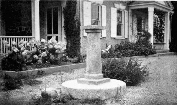
Photographs by C. M. D'Enville
A Sun Dial Made of Concrete An excellent illustration of the possibility which concrete offers in ornamental as well as practical construction. This sun dial, complete, cost approximately ten dollars, and may be duplicated by any clever boy. See formula for concrete on page 20.
"Boys," he said to them next morning, "why not try your hands on a sundial? You will find it easy to make, and if properly set up it will keep accurate time. There is a nice place for one near the bridge on the new grounds, as there is a stump there, the top of which can be cut off smooth, and it stands out full in the sun.
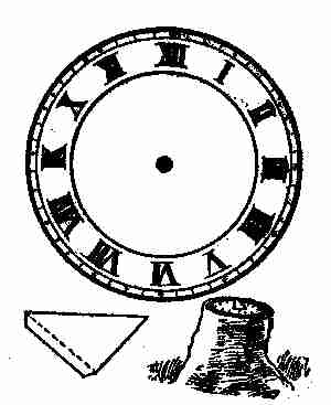
Fig. 64. Sundial
"Go to our jeweller in the city and get him to give you an old tin clock-dial, like the one shown in Fig. 64. If you cannot get one, make a dial out of cardboard yourself, printing the hours in ink. Slit the dial from the centre to a point directly underneath the number 12, if you have Arabic numerals on your dial.
"Then cut out a triangular blade or gnomon, like the one shown. If your dial is of tin, make the blade of tin, or cardboard if your dial is of cardboard.
"Insert the blade in the slit of the dial and secure it to the top of the stand you have selected—with tacks if your dial is cardboard, with small nails if it is tin. Then your sundial will be completed and ready for business.
"At 12 o'clock, there will be only the shadow of the thin edge of the blade over the dial, but as the sun moves, so will the shadow, so as to tell always the correct time of day. You will find this not only a useful but a quaint and artistic addition to the grounds, and not at all expensive."
"Papa," said George, "mamma wants a flower bed made in the front garden, and she would like to have it an oval or elliptical shape. I have promised to make it for her, but I do not know how to make the shape, and I wish you would tell me."
"Certainly, my boy, I will show you. It can be done easily with a string and two wooden pegs. Follow the lines I make on the blackboard. First we must decide on the length and width of the oval or rather ellipse required. Then draw two straight lines, A B and C D, Fig. 65, equal to the two axes, and bisect or halve each at right angles. Set off from C half the length of the great axis at E and F, which are the two foci of the ellipse. Take an endless string, as long as the three sides of the triangle, C E F, fix two pins or nails in the two foci, one at E and one at F. Lay the string around E and F, stretch it with a marker G, and it then will describe the desired ellipse.
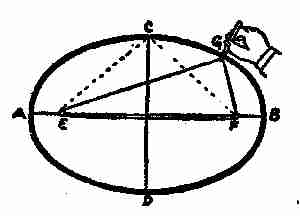
Fig. 65. Drawing an ellipse
"This is not at all difficult, and will answer for any kind of an ellipse, short or long, narrow or wide. This is called the "gardener's method." The main thing is to get the two points, E and F. This distance is always half of the long diameter A B, no matter what that may be, and this distance is then transferred by taking C as the starting point, measuring from there until the other point of measurement cuts the long diameter, as at E and F.
"The ellipse has many peculiar and useful qualities, which you will doubtless discover before long."
IX TIDES
Now, papa!" said Jessie the following evening, after Mr. Gregg and the family had strolled down to the river bank to enjoy the cool air, "you promised to tell me about the tides and the moon—when you could spare time. Haven't you got time now?"
"I may as well say all I intended now, my dear, and leave some other matters for future consideration. As this subject may tax your patience, I hope you, Fred, and George, will give me your earnest attention.
"In order to have a clear understanding of the movements of the tides and their supposed causes, you must know something of the moon's influence over them; as this knowledge will aid you very much in remembering what I am about to say.
"The earth is a globular body. One reason for this belief, among many others, is that sailors or others who go to sea soon observe that as they sail from shore, the lower portions of mountains, steeples or other high objects, are gradually lost sight of while the higher parts do not so soon disappear. Persons on shore first notice the upper portions of masts, and the smoke-stacks of approaching vessels, which would not be the case, if the earth were a plane, but is very easily accounted for, on the supposition of its being a sphere, as you can readily understand by looking at Fig. 66. Several navigators have sailed completely round the earth by continuing in the same direction, and coming at last to the same place from which they started. The earth, however, is not a perfect sphere but a spheroid like an orange; having its equatorial longer than its polar diameter or axis. It is flattened at the poles, and more protuberant at the equator. The diameter at the equator is 7,977 miles, and at the poles 7,940, a difference of 37 miles.
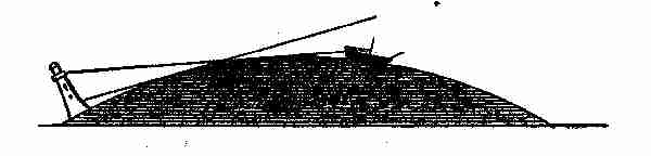
Fig. 66. Proof of earth's rotundity
"You know that the cause of day and night is the rotation of the earth on its own axis. It shows a large portion of its surface to the sun continually, or in other words, the sun is always shining on some portion of the earth's surface. You are also aware of the earth and its satellite, the moon, both being held in their orbits by the sun's attraction, the moon being further kept in her orbit by the attraction of the earth. Now the earth is composed of three main elements, air, water, and land, and if you consider, for a moment, that the daily rotatory movement of the earth is something like 1,000 miles an hour, this rapid speeding through space must have some effect on air and water in assisting or retarding their flow.
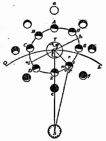
Fig. 67. Phases of the moon
"Nature has divided time, and man has named and subdivided it into years, months, and days. The natural month, however, does not consist of four weeks, nor is the natural year made up of the twelve calendar months given us by the almanac. A natural, or lunar, month is the time the moon takes to perform her journey round the earth, which is 27 days 7 hours, and 43 minutes; this is called the periodical month, while the average calendar or synodical month consists of 29 days 12 hours and 44 minutes. The light of the moon is borrowed from the sun, for if it were her own light, she would shine all the time and not be subject to her present phases. The moon is seen by means of the light which comes to it from the sun being reflected from it. Its changes, or phases, depend upon its relative position to the earth and the sun. When the moon is in opposition to the sun at A (Fig. 67) the lighted side is turned toward the earth, as A, and it appears full. When the moon is in conjunction at E with the sun, its dark side is turned toward us, and it is invisible, as at e. As it proceeds in its orbit, as at F, a small part of the light side is seen, and then we have what is called a new moon; and we continue to see more and more of the light side, as the moon approaches at G and H, to the state of opposition or full moon. The waning or decreasing of the moon takes place in the same manner, but in a contrary order. The earth must perform the same office to the moon that the moon does to us; and it will appear to the inhabitants of the moon (if there be any), like a very magnificent moon, being to them about thirteen times as large as the moon is to us and it will also have the same changes or phases. Hence it is evident, that one half of the moon is never in darkness, the earth constantly affording it a strong light, during the absence of the sun; but the other half has a fortnight's light and darkness by turns.
"The moon's orbit is elliptical, and she also rotates on her axis and takes the same time to circle the earth, consequently every part of the moon is successively presented to the sun, yet the same hemisphere is always turned to the earth. This has been discovered by observation with good telescopes. The length of a day and night in the moon is more than twenty-nine and a half days of ours; and while her year is the same length as ours, being measured by her journey around the sun with us, so she has but twelve days and a third in a year. Another remarkable circumstance is that the moon's hemisphere next the earth is never in darkness, for when it is turned from the sun, it is illuminated by light reflected from the earth in the same manner as we are lighted by a full moon. The other hemisphere of the moon however, has a fortnight's light and darkness by turns. If there are inhabitants in the moon, which is doubtful, the satellite will appear to them to be about thirteen times as large as the moon does to us, and when it is new moon to the earth, it is full earth to the moon.
"There are many things regarding our relationship to the moon that would be of interest, if I had time to explain them, such as eclipses, the moon's surface as seen through telescopes, its supposed influence on the weather, etc., but I fear too much moon might prove tiresome. Beside I have shown you sufficient to enable you to understand the relationship existing between the moon and the tides, generally accepted as the true theory.
"If we agree that the tides are occasioned by the attraction of sun and moon, more particularly the latter, we can readily understand their dependence on some known and determinate laws. Our almanacs published long in advance give the exact time of high water at any prominent port in the United States on the morning and afternoon for every day in the year; and seafaring men can tell you when the tide will be high or low, notwithstanding the fact that these movements are not fixed. They know from experience that the time of ebb and flow varies about three quarters of an hour each day.
"The first person who clearly pointed out the accepted cause of the tides and showed its agreement with the effects, was Sir Isaac Newton. He discovered a relationship between the moon and the tides, and by the application of his new principles of geometry, the attraction was made clear.
"The ocean, it is well known, covers more than one half the globe; and this large body of water is found to be in continual motion, ebbing and flowing alternately, without the least intermission. For instance, if the tide is now at high water mark, in any port or harbour which lies open to the ocean, it will presently subside, and flow regularly back for about six hours, when it will be found at low water mark. After this it will again gradually advance for six hours; and then recede in the same time to its former situation, rising and falling alternately twice a day, or in the space of about twenty-four hours. The interval between its ebb and flow is not precisely six hours, for there is a little difference in each tide; so that the time of high water does not always happen at the same hour, but is about three quarters of an hour later each day, for about thirty days, when it again recurs as before. For example, it is high water to-day at noon, it will be low water at eleven minutes after six in the evening; and, consequently, after two changes more, the time of high water the next day will be at about three quarters of an hour after noon; the day following it will be at about half an hour after one, the day following that at a quarter past two, and so on for thirty days; when it will again be found to be high water at noon, as on the day the observation was first made. This exactly answers to the motion of the moon which rises every day about three quarters of an hour later than upon the preceding one, and by moving in this manner round the earth, completes her revolution in about thirty days, and then begins to rise again at the same time as before.
"To make the matter still plainer; suppose, at a certain place, it is high water at three o'clock in the afternoon, upon the day of the new moon; the following day it will be high water at three quarters of an hour after three; the day after that at half an hour past four; and so on till the next new moon, when it will again be high water exactly at three o'clock, as before. By observing the tides continually at the same place, they will always be found to follow the same rule; the time of high water, upon the day of every new moon, being exactly at the same hour, and three-quarters of an hour later every succeeding day.
"The change of the tides is in such exact conformity with the motion of the moon that, independently of mathematical calculations, a thoughtful person would certainly be induced to look to her as their cause.
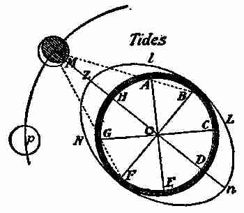
Fig. 68. Theory of the tides
"The waters at Z, on the side of the earth, A, B, C, D, E, F, G, H, next the moon M, (Fig. 68) are more attracted by the moon than the central parts of the earth, O, and the central parts are more attracted by her than the waters on the opposite side of the earth at n; and therefore the distance between the earth's centre and the waters on its surface under and opposite to the moon will be increased. Let there be three bodies at H, O, and D; if they are all equally attracted by the body M, they will all move equally fast toward it, their mutual distance from each other continuing the same. If the attraction of M is unequal, then that body which is most strongly attracted will move most quickly and will increase its distance from the other body. M will attract H more strongly than does O, by which the distance between H and O will be increased, and a spectator on O will perceive H rising higher toward Z. In like manner, O being more strongly attracted than D, it will move farther toward M than D does; consequently the distance between O and D will be increased; and a spectator on O, not perceiving his own motion, will see D receding farther from him towards N; all effects and appearances being the same, whether D recedes from O, or O from D.
"Suppose now there is a number of bodies, as A, B, C, E, F, G, H, placed round O, so as to form a flexible or fluid ring; then, as the whole is attracted toward M, the parts at H and D will have their distance from O increased; whilst the parts at B and F being nearly at the same distance from M as O is, these parts will not recede from one another; but rather by the oblique attraction of M, they will approach near to O. Hence, the fluid ring will form itself into an ellipse Z, n, L, N, whose longer axis n, O, Z, produced will pass through M, and its shorter axis B, O, F, will terminate in B and F. Let the ring be filled with fluid particles, so as to form a sphere round O; then, as the whole moves toward M, the fluid sphere being lengthened at Z and n will assume an oblong or oval form. If M is the moon, O the earth's centre, A, B, C, D, E, F, G, H, the sea covering the earth's surface, it is evident, by the above reasoning, that whilst the earth by its gravity falls toward the moon, the water directly below at B will swell and rise gradually toward her; also the water at D will recede from the centre, (strictly speaking, the centre recedes from D) and rise on the opposite side of the earth; whilst the water at B and F is depressed, and falls below the former level. Hence as the earth turns round its axis from the moon to the moon again in 243⁄4 hours, there will be two tides of flood and two of ebb in that time, as we find by experience.
"That this doctrine may be still more clearly understood, let it be considered that, although the earth's diameter bears a considerable proportion to the distance of the earth from the moon, yet this diameter is almost nothing when compared to the distance of the earth from the sun. The difference of the sun's attraction, therefore, on the sides of the earth under and opposite to him, will be much less than the difference of the moon's attraction on the sides of the earth under and opposite to her; and, for this reason, the moon must raise the tides much higher than they can be raised by the sun. The effect of the sun's influence, in this case, is nearly three times less than that of the moon. The action of the sun alone would, therefore, be sufficient to produce a flow and ebb of the sea; but the elevations and depressions caused by this means would be about three times less than those produced by the moon.
"The tides, then, are not the sole production of the moon, but of the joint forces of the sun and moon together. Or, properly speaking, there are two tides, a solar one and a lunar one, which have a joint or opposite effect, according to the situation of the bodies which produce them. When the actions of the sun and moon conspire together, as at the time of new and full moon, the flow and ebb become more considerable; and these are then called the spring tides. But when one tends to elevate the waters while the other depresses them, as at the moon's first and third quarters, the effect will be exactly the contrary: the flow and ebb, instead of being augmented, as before, will now be diminished; and these are called the neap tides.
"To explain this more completely, let Fig. 69 represent the sun, Z, H, R, the earth, and F and C the moon at her full and change. Then, because the sun S, and the new moon C, are nearly in the same right line with the centre of the earth O, their actions will conspire together, and raise the water above the zenith Z, or the point immediately under them, to a greater height than if only one of these forces acted alone. But it has been shown that when the ocean is elevated to the zenith Z, it is also elevated to the opposite point, or nadir, at the same time; and therefore in this situation of the sun and moon, the tides will be augmented. And again, whilst the full moon F raises the waters at N and Z, directly under and opposite to her, the sun S, acting in the same right line, will also raise the waters at the same point Z and N, directly under and opposite to him. Therefore, in this situation also, the tides will be augmented; their joint effect being nearly the same at the change as at the full; and in both cases they occasion what are called the spring tides.
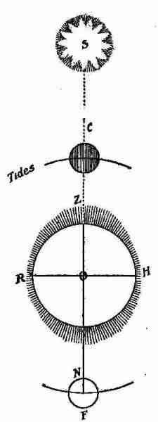
Fig. 69. Attractions of the moon
"On this theory, the tides ought to be highest directly under and opposite to the moon; that is, when the moon is due north and south; but we find that in open seas, where the water flows freely, the moon is generally past the north and south meridian of the place where it is high water. The reason is obvious; for though the moon's attraction were to cease altogether when she was past the meridian, the motion of ascent communicated to the water before that time would make it continue to rise for some time after; much more must it do so when the attraction is only diminished. A little impulse given to a moving ball will cause it still to move farther than otherwise it could have done; and experience shows that the day is hotter about three in the afternoon than when the sun is on the meridian, because of the increase made to the heat already imparted.
"Tides do not always answer to the same distance of the moon from the meridian at the same place, but are variously affected by the action of the sun, which brings them on sooner when the moon is in her first and second quarters, and keeps them back later when she is in her third and fourth; because, in the former case, the tide raised by the sun alone would be earlier than the tides raised by the moon; and in the latter case, later.
"The sea, being put in motion, would continue to ebb and flow for several times, even though the sun and moon were annihilated, and their influences at an end, on the same principle that if a basin of water is once agitated, the water will continue to move for some time after the basin is left to stand still. A pendulum, put in motion by the hand, continues to make several vibrations without any new impulse. When the moon is at the equator, the tides are equally high in both parts of the lunar day, or time of the moon's revolving from the meridian to the meridian again, which is 24 hours 50 minutes. But as the moon declines from the equator toward either pole, the tides are alternately higher and lower at places having north or south latitude. One of the highest elevations, which is that under the moon, follows her toward the pole to which she is nearest, and the other declines toward the opposite pole; each elevation describing parallels as far distant from the equator, on opposite sides, as the moon declines from it to either side; and consequently the parallels described by those elevations of the water are twice as many degrees from one another as the moon is from the equator; then increase their distance as the moon increases her declination, till it is at the greatest, when these parallels are, at a mean state, 47 degrees from one another; and on that day the tides are most unequal in their heights. As the moon returns toward the equator, the parallels described by the opposite elevations approach toward each other, until the moon comes to the equator, and then they coincide. As the moon declines toward the opposite pole, at equal distances, each elevation describes the same parallel in the other part of the lunar day which its opposite elevation described before. Whilst the moon has north declination, the great tides in the northern hemisphere are when she is above the horizon; and the reverse whilst her declination is south.
"In open seas, the tides rise to very small heights in proportion to what they do in wide-mouthed rivers, opening in the direction of the stream of tide. In channels growing narrower gradually, the water is accumulated by the opposition of the contracting bank—like a gentle wind, little felt on an open plain, but stronger and brisk in a street; especially if the wider end of the street is next the plain, and in the way of the wind.
"The tides are so retarded in their passage through different shoals and channels, and otherwise so variously affected by striking against capes and headlands, that in different places they happen at all distances of the moon from the meridian, consequently at all hours of the lunar day.
"There are no tides in lakes because they are generally so small that when the moon is vertical she attracts every part of them alike; and, therefore, by rendering all the waters equally light, no part of them can be raised higher than another. The Mediterranean and Baltic Seas suffer very small elevations, because the inlets by which they communicate with the ocean are so narrow that they cannot, in so short a time, receive or discharge enough to raise or sink their surface sensibly.
"Air being lighter than water and the surface of the atmosphere being nearer to the moon than the surface of the sea, it cannot be doubted that the moon raises much higher tides in the air than in the sea. Therefore many have wondered why the mercury does not sink in the barometer when the moon's action on the particles of air makes them lighter as she passes over the meridian. But we must consider, that as these particles are rendered lighter, a greater number of them are accumulated, until the deficiency of gravity is made up by the height of the column; and then there is an equilibrium, consequently an equal pressure upon the mercury as before; so that it cannot be affected by the aerial tides. It is probable, however, that stars seen through an aerial tide of this kind will have their light more refracted than those which are seen through the common depth of the atmosphere; and this may account for the supposed refractions of the lunar atmosphere that have been sometimes observed.
"You see now how the tides are caused; while there may be some influences at work other than those exerted by the sun and moon, the latter are the chief ones, so I will not attempt to explain any other.
"Here, on the Passaic River, we do not have excessive tides, as the highest on the coast near us seldom rise over ten or twelve feet. As a rule, tides rise highest and strongest in those places that are narrowest. In the Black Sea and the Mediterranean, the tides are scarcely perceptible, while at the mouth of the Indus, in the Bay of Fundy, and other places, they rise thirty or more feet at times. The general rise, however, in mid-ocean, is from eleven to twelve feet.
"The diameter of our moon is nearly 2,200 miles, and her distance from the earth is about 240,000 miles; so you see it is not her size, but her proximity to the earth that gives her so much influence over the tides; for the sun, which is many times larger than the earth and moon combined, because of its being some ninety-three millions of miles away, exerts only one sixth of the attraction on the earth that the moon does.
"These facts, children, should be remembered, as you may often be called upon to make use of them.
"Oh, papa!" said Jessie "how many wonderful things there are in this world."
"But I have not told you all, my dear. There is much more to learn, but I hope the knowledge you have now acquired will act as an incentive, and cause you to pursue this study further."
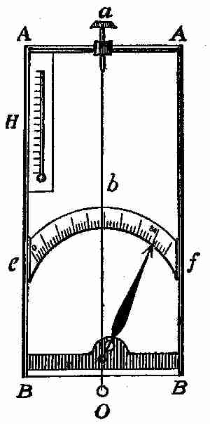
Fig. 70. Hygrometer
Next morning Fred asked his father to enlighten himself and George regarding the making of a few simple meters, such as barometer, hygrometer, and a thermometer. He also wished to know if it would be possible for him to make a boomerang. Mr. Gregg told him he would be pleased to help him, and that there would be no difficulty in making a boomerang if he went to work at it earnestly.
On the arrival of his father that evening, the subject was again introduced, and Mr. Gregg using the blackboard, laid out the following drawing and wrote the accompanying instructions.
"The best hygrometer of absorption is (according to Deschanel) that of De Saussure, consisting of a hair deprived of grease, which by its contractions moves a needle. When the hair relaxes, the needle is caused to move in the opposite direction by a weight which serves to keep the hair always tight as seen in the illustration, Fig. 70. The hair contracts as the humidity increases. In the accompanying illustration A A and B B represent the frame; e f, the scale; a, screw for tightening the hair; b, the hair; O, weight; H, thermometer.
Fig. 71. Index of Hygrometer
"A neater hygrometer, and one on the same principle, may be made by taking an old tooth powder box (as deep a one as possible, since the longer the string, the more sensitive it is), and boring a hole through the centre of the top and bottom. Paste a kind of dial in paper on the top of the box; take a piece of catgut, or small fiddle string, and push it up through the hole in the bottom and out at the one in the lid. Glue the bottom end immovably, and let the top end move freely: make a small index of a strip of whalebone (Fig. 71); bore a hole in the centre, and fix it on the catgut with glue. Wet the catgut, see which way it turns, and mark 'wet' and 'dry', accordingly on the dial.
"So much for the hygrometer. Now about that curious thing, the boomerang. If the following directions are closely adhered to, and the proper shape followed, a regular Australian boomerang will result. It is not difficult to make. Take a piece of hard wood, the natural shape of one of the segments of an ordinary wheel felloe, or bend in the wood; let it be 1⁄4 inch thick, shaped as at Fig. 72, to be held in the right hand at A, which shows the way the edges of the side facing the left hand must be bevelled off. It requires a slight curve on the flat side; so that, if on a table, each end would turn about 1⁄8 inch. It is then a part of a very fine pitch screw, in motion similar to a piece of slate jerked into the air, the sole difference being due to the slight curve in the back, which gives the screw motion, in conjunction with the forward and rotatory motion given by the hand. Sheet-iron would not do, as there would not be thickness to show the bevelled edge. The boomerang was made in the form of a cross, with four legs of equal length, bevelled, but it does not work as well as the regular form. You must be careful in throwing it as it may strike you on return."
Fig. 72. Boomerang
George asked his father to describe one and to explain its uses. Mr. Gregg told the boys that a boomerang, as used by the aborigines of Australia for a weapon or missile of war or in the chase, consisted of a flat piece of hard wood bent or curved in its own plane, and from 16 inches to 2 feet long. Generally, but not always, it is flatter on one side than on the other. In some cases the curve from end to end is nearly an arc of a circle; in others it is rather an obtuse angle than a curve, and in a few specimens there is a reverse curve toward each end. In the hand of a skilful thrower, the boomerang can be projected to a great distance, and made to ricochet almost at will. It can be thrown in a curved path, somewhat as a ball can be "screwed" or "twisted," and it can be made to return to the thrower, striking the ground behind him. It is capable of inflicting serious wounds.