PART II.—APPLICATIONS.
Reading edition

Section I.—Lettering, Bordering, and North Points.
Lettering.
—The lettering of a plan, map, or drawing of any kind, occupies a prominent and conspicuous position, and may be considered as forming an essential part of the drawing. It is, therefore, obvious that the character of the lettering, and the degree of finish introduced into its execution, will have an important influence on the general appearance of the drawing. Nothing detracts more from the value of a map, considered as a work of art, than a bad style of lettering, while, on the other hand, a well-chosen and well-executed style is both pleasing to the eye, and produces on the mind an impression of accuracy in the more important features of the work. Hence it is not merely desirable, but necessary, that the draughtsman should acquire the ability to form letters correctly and neatly, especially if he be engaged on topographical drawings, into which lettering enters very largely.
The formation of letters requires great attention and long practice. It is not a matter in which much assistance is to be derived from descriptions or written instructions of any kind; practice alone from good models will give the requisite skill. The difficulty of forming the letters correctly and of uniform dimensions may, however, be considerably lessened by using guide lines drawn in pencil, to be afterwards erased. Such lines are called construction lines, and the mode of employing them is shown in Plate 4. A careful study of this Plate will give the student a clear understanding of the use of these lines, which could not be imparted by pages of description. A reference to the letters B, E, and T, in connection with the construction lines will show most readily the nature and the degree of assistance afforded by the latter.
In making capitals, each letter must be sketched in pencil; the outline must then be drawn in ink with a firm and steady line, and afterwards filled up with the pen. In forming the small roman and italic letters, three construction lines are drawn, the lower two to limit the height of the ordinary letters, and the upper one to limit the height of such letters as d and l, and the capitals. The heavy parts of these letters are made at once by a bold pressure of the pen. The curved portions should be carefully distinguished from the straight. The letters a, c, g, o, s, &c., for example, are composed wholly of curved lines. They should be drawn symmetrically, and their width should be only a little less than their height. The round portion of the g should not quite reach to the lower line. A perfect regularity should be maintained throughout the letters, as the beauty of their appearance depends greatly on this. Care must also be taken, in italic writing, to keep the inclination the same everywhere. Manuscript lettering should be more extended than the clear roman or italic type, for crowding greatly mars its appearance.
The character of the letters employed should be in accordance with that of the drawing upon which they are to appear. Thus for engineering and mechanical drawings, there is nothing more suitable generally than the plain block letter. But on drawings of a more artistic and ornamental character, a more elaborate form of letter may and should be used. And of these elaborate forms, there will always be one more suitable than the rest to the particular character of the drawing. The choice of this form is a matter to be left entirely to the judgment and the taste of the draughtsman.
Another matter on which the draughtsman will have to exercise his judgment is the size of the letters employed. This must manifestly be in accordance, first, with the character of the object denoted, and, second, with the scale of the drawing. With regard to the former of these conditions, it is obvious that propriety will demand a larger letter for the city than the town, for the town than the village, for the village than the farm, and for the mansion than the gate-lodge. This propriety of relative importance must be everywhere observed. The different types of lettering are arranged in the order of importance as follows:—1, The upright capital; 2, the inclined capital; 3, the upright roman, or ordinary small type; and 4, the small italic. The draughtsman will have to exercise his judgment in suiting the size to the scale of the map, but the following Table may be taken as a general guide:—
Scale. Height of Upright Capitals. Height of Small Roman.
1⁄600, or one inch to fifty feet. Six-tenths of an inch. Twelve-hundredths of an inch.
1⁄2640, or two feet to a mile. Four „„ Eight „„
1⁄5280, or one foot to a mile. Three „„ Six „„
1⁄10560, or four inches to a mile. Two „„ Four „„
The thickness of the capital should be one-seventh of the height.
As far as practicable, the lines of lettering should be parallel to the base of the drawing. Frequently, however, cases will occur in which it will be desirable to letter in other directions and in curved lines. In writing along a curved or very irregular outline, the course of a river or the boundary of an estate, for example, an agreeable effect is produced by making the lines of lettering conform in some degree with the outlines against which they are written.
The arrangement of the letters in titles and the effective disposition of the words are also matters requiring great care and some taste. The design and the execution of the title afford another opportunity of enhancing the beauty of a drawing by a display of striking arrangement and appropriate ornamentation. Plates 7 and 8 show some useful models for plans, and Plate 25 contains some specimens of flourishes which may frequently be introduced with pleasing effect. The form which the title shall assume and the space which it shall occupy must be determined before beginning to put it upon the drawing. To avoid erasures, it is well to sketch roughly upon a piece of paper, a trial title, emendations in which can be easily made. When found satisfactory, draw a vertical centre line, which should pass through the middle letter of each line. Apply this centre line to the centre line of the title on the drawing, and lightly mark in with the pencil the position of each letter. When this method is not adopted, the middle letters should be put in first upon the centre line, and the others afterwards inserted from left to right, and from right to left.
In maps, the title may be placed outside the border if it consist of one line only, but if it occupy more than one line, it should be placed within the border. Generally, it should be placed in one of the corners of the map, and its size should bear some proportion to that of the map. The letters composing the name of the locality, which is usually the most important word, should not exceed in height three-hundredths of the length of the short side of the border. The letters of the other words will vary in size according to their relative importance.
Borders.
—Plain borders usually consist of two lines, the outer one heavy, and the inner one light. The heavy line should be equal in breadth to the blank space between it and the light line, and the total breadth of the border, that is, of the two lines and the space between them, should be one hundredth part of the length of the shorter side. Ornamental corners may be made to embellish a drawing considerably, and they afford some scope to the fancy and the taste of the draughtsman. Several examples of borders and ornamental corners will be found in the accompanying Plates.
North Points.
—The meridian or north and south line is an indispensable adjunct to every topographical drawing. When the extent of country represented is considerable, it is usual to make the top of the map the north, and in such a case the side border lines are meridian lines. Frequently, however, in plans, the shape of the ground does not admit of this arrangement, and then it becomes necessary to mark a meridian on some part of the map. This line is usually made a conspicuous one, and its north extremity is often ornamented with some fanciful device. The ornamentation of the meridian line should be in keeping with the rest of the map. Plate 9 contains several examples which may be adopted or modified as deemed desirable.
Section II.—Scales.
To all drawings which do not show the full size of the objects represented, it is necessary to affix the scale according to which the objects are drawn. Such a scale is called a scale of lengths or distances, because, by means of it, the distance from one point to another is ascertained. The scale of distances does not contain very minute subdivisions, and consequently is not suitable for use in constructing the drawing. For the latter purpose, another scale, similarly but more minutely divided, is employed, and is known as the scale of construction. A familiarity with the modes of constructing both of these scales should be early acquired by the young draughtsman.
Scales of Distances.
—One means of denoting the scale of a drawing is furnished by what is called its representative fraction, the denominator of which shows how many times greater the actual length is than that in the drawing. Thus a scale of 1⁄24 shows that 1 inch on the drawing represents 24 inches on the object; in other words, that the object is twenty-four times larger than the drawing. But in addition to this representative fraction, it is usual to affix a graduated straight line, termed a scale, for the purpose of conveniently measuring distances upon it. It is manifest that the unit of length in this scale must bear the same ratio to the real unit of length that a line in the drawing bears to the line which it represents. Thus if the representative fraction be 1⁄24, 1 inch on the scale will represent 2 feet.
Scales of distances are usually of such a length as to be a multiple of 10 linear units of some kind, as 100 miles, 50 chains, 20 feet; and this length should also be such as to allow of long lines being taken off at one measurement. To construct the scale, two light lines should be drawn at a suitable distance apart, and below the lower of these lines and at a distance from it equal to one-third of the space between them, a third and heavy line should be drawn. The primary divisions may then be made with the compasses in the following manner. Supposing the number of divisions to be five, open the dividers to what appears to be the fifth part of the line, and step this distance along the line; if the fifth step exceed or fall short of the end of the line, close or open the dividers 1⁄5 of the distance, and repeat the trial. This is the quickest and, for large divisions, the most accurate method of dividing a line. To render the divisions more distinct, draw a heavy line between the two light lines in alternate divisions. The left-hand division must be subdivided into the units or lesser measures of which it is made up. For example, if the primary divisions are each of 10 feet, the subdivisions will be feet; if they represent feet, the subdivisions will be inches, and so on. The subdividing should be performed in the following manner. Having erected a perpendicular of indefinite length from the left-hand extremity of the scale, take with the compasses from any scale the number of divisions into which it is required to divide the part. With this distance in the compasses, strike, from the first primary or zero division, an arc cutting the perpendicular, and join the point of intersection to the centre from which the arc is struck. Thus we shall have a right-angled triangle formed of the first primary division of the scale, the perpendicular and the radius, the latter being the hypothenuse (see Fig. 79). Mark on the hypothenuse the divisions to which it was made equal, and from the points of division let fall perpendicular lines upon the scale. These will divide the latter into the required number of equal parts. The length of the hypothenuse should be so chosen as to make an angle not greater than 50° with the base.
Fig. 79.
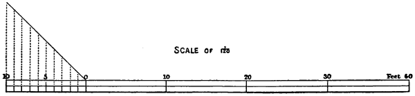
Larger illustration (19 kB).
The total length of the scale will be determined by the greatest length which it is required to read off at once, and in the following manner. Thus, let it be required to construct a scale of 1⁄24, = 1⁄2 inch to the foot, to show 12 feet. Here ·5 inch : x inches :: 1 inch : 12 inches; whence x = 12 × ·5 = 6 inches. This distance of 6 inches must, therefore, be set off upon the lines intended for the scale, and divided in the manner described above. Again, to construct a scale of 1⁄10560, = 6 inches to a mile, to show 100 chains. Since 6 inches represents 5280 feet or 5280⁄60 = 80 chains, the proportion becomes 6 : x :: 80 : 100; whence x = 600⁄80 = 71⁄2 inches. If the scale is 1⁄3960 = 16 inches to a mile, = 5 chains to an inch, and the distance to be shown is 30 chains, we have 1 : x :: 5 : 30; or x = 30⁄5 = 6 inches. In a scale of 10 yards to the inch, for example, the representative fraction is 10 × 3 × 12 = 1⁄360. So, on the contrary, 1⁄360 = 360⁄36 = 10 yards to the inch. Sometimes it is required to construct a comparative scale, that is, a scale having the same representative fraction, but containing other units. Thus suppose, for example, we have a Russian plan on which is marked a scale of archines measuring a length of 50 archines. It is required to draw upon this plan a comparative scale of yards, upon which a distance of 50 yards may be measured. The Russian archine = ·777 yard. Hence we have the proportion 50 : x :: ·777 : 1, whence x = 50⁄777 = 64·35 archines. Measure off this length from the Russian scale, and upon it construct the English scale in the manner already described. This scale may then be used to measure distances on the plan.
Amongst Continental nations, decimal scales are usually employed, which are far more convenient in practice than those involving the awkward ratios of miles, furlongs, chains, yards, feet, and inches. The decimal scale has also been adopted for the United States’ Coast Survey, the smallest publication scale of which is 1⁄30000; this is also the scale of the new map of France.
In choosing a scale, regard must be had alike to the purposes for which the drawing is intended, and to the nature and the amount of detail required to be shown. Thus a larger scale is required in plans of towns than in those of the open country; and the smaller and more intricate the buildings, the larger should the scale be. Also a plan to be used for the setting out of works should be to a larger scale than one made for parliamentary purposes.
The following Tables, given by Rankine in his ‘Civil Engineering,’ enumerate some of the scales for plans most commonly used in Britain, together with a statement of the purposes to which they are best adapted.
Horizontal Scales.
Ordinary Designation of Scale. Fraction of real Dimensions. Use.
1.— 1 inch to a mile 1⁄63360 Scale of the smaller Ordnance maps of Britain. This scale is well adapted for maps to be used in exploring the country.
2.— 4 inches to a mile 1⁄15840 Smallest scale permitted by the Standing Orders of Parliament for the deposited plans of proposed works.
3.— 6 inches to a mile 1⁄10560 Scale of the larger Ordnance maps of Great Britain and Ireland. This scale, being just large enough to show buildings, roads, and other important objects distinctly in their true forms and proportions, and at the same time small enough to enable the eye of the engineer to embrace the plan of a considerable extent of country at one view, is on the whole the best adapted for the selection of lines for engineering works, and for parliamentary plans and preliminary estimates.
4.— 6·366 inches to a mile 1⁄10000 Decimal scale possessing the same advantages.
5.— 400 feet to an inch 1⁄4800 Smallest scale permitted by the Standing Orders of Parliament for “enlarged plans” of buildings and of land within the curtilage.
6.— 6 chains to an inch 1⁄4752 - Scale answering the same purpose.
7.— 15·84 inches to a mile 1⁄4000 Scales well suited for the working surveys and land plans of great engineering works, and for enlarged parliamentary plans.
8.— 5 chains to an inch, or 16 inches to a mile. 1⁄3060
(Scale 8 is that prescribed in the Standing Orders of Parliament for “cross sections” of proposed railways, showing alterations of roads.)
9.— 25·344 inches to a mile 1⁄2500 Scale of plans of part of the Ordnance survey of Britain, from which the maps before mentioned are reduced. Well adapted for land plans of engineering works and plans of estates.
10.— 200 feet to an inch 1⁄2400 Scale suited for similar purposes. Smallest scale prescribed by law for land or contract plans in Ireland.
11.— 3 chains to an inch 1⁄2376 Scale of the Tithe Commissioners’ plans. Suited for the same purposes as the above.
12.— 100 feet to an inch 1⁄1200 Scale suited for plans of towns, when not very intricate.
13.— 88 feet to an inch, or 60 inches to a mile. 1⁄1080 Scale of the Ordnance plans of the less intricately built towns.
14.— 63·36 inches to a mile 1⁄1000 Decimal scale having the same properties.
15.— 44 feet to an inch, or 120 inches to a mile. 1⁄528 Scale of the Ordnance plans of the more intricately built towns.
16.— 126·72 inches to a mile 1⁄500 Decimal scale having the same properties.
17.— 30 feet to an inch 1⁄360 - Scales for special purposes.
18.— 20 feet to an inch 1⁄240
19.— 10 feet to an inch 1⁄120
Vertical Scales.
Ordinary Designation of Vertical Scale. Fraction of real Height. Horizontal Scales with which the Vertical Scale is usually combined. Exaggeration. Use.
from
1.— 100 feet to an inch 1⁄1200 1⁄15840 to 1⁄10560 13·2 to 8·8 Smallest scale permitted by the Standing Orders of Parliament for sections of proposed works.
2.— 40 feet to an inch 1⁄4800 1⁄4800 to 1⁄3960 10 to 8·25 Smallest scale permitted by the Standing Orders of Parliament for cross sections showing alterations of roads.
3.— 30 feet to an inch 1⁄360 1⁄3960 to 1⁄2376 11 to 6·6 - Scales suitable for working sections.
4.— 20 feet to an inch 1⁄240 1⁄3960 to 1⁄2376 16·5 to 9·9
The vertical scale, or scale of heights, is always much greater than the horizontal scale or scale of distances, and the proportion in which the vertical scale is greater than the horizontal, is called the exaggeration of the scale. This exaggeration is necessary, because the differences of elevation between points on the ground are in general much smaller than their distances apart, and would therefore, without exaggeration, be unapparent, and also because, in the execution of engineering works, accuracy in levels is of more importance than accuracy in horizontal positions.
Scales of Construction.
—Scales of construction are intended to afford means of measuring more minute quantities than scales of distances. Of the former there are two kinds, known respectively as the Diagonal and the Vernier scale. The diagonal is the more frequently employed. Its construction involves no peculiar difficulty, as it consists simply of an ordinary scale of distances, with the addition of a number of parallel lines crossed by other parallel lines drawn diagonally from the smaller points of division. An example will best show the construction and mode of using this scale. Suppose it to be required to construct a scale of 10 miles to the inch, showing furlongs diagonally; the scale to measure 50 miles. Here 1 : 10 :: x : 50, whence x = 5 inches. Divide this length of 5 inches into five equal parts, and the first part into tenths to show miles, in the manner already described for scales of distances. Then, since it is required to show furlongs or eighths of a mile, eight equidistant parallel lines must be drawn above the scale, at a convenient interval apart, as shown in Fig. 80. Produce the primary points of division to meet the top parallel; and from the last secondary point of division draw a line to the point in which the extreme primary division meets the top parallel. Draw from the other points of division, lines parallel to this one, and the scale will be complete. It will be seen that the inclined lines are the diagonals of the rectangular figures formed by the top and bottom parallels and vertical lines drawn from the smaller points of division.
Fig. 80.
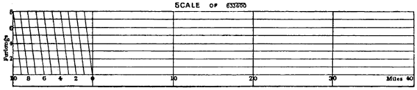
Larger illustration (31 kB).
To use this scale, suppose a length of 24 miles 5 furlongs is required. Place one leg of the dividers upon the point in which the fourth diagonal intersects the fifth parallel, and extend the other to the point in which the primary division marked 20 intersects the same parallel. In like manner, if the distance required be 33 miles 3 furlongs, it must be taken from the intersection of the third diagonal with the third parallel, to the intersection of the primary division marked 30 with the same parallel.
It is obvious that if a scale of feet showing inches diagonally be required, twelve equidistant parallel lines must be drawn instead of eight as in the foregoing example where furlongs are required. The diagonal scale possesses the important advantages of accuracy and distinctness of division which render it very suitable as a scale of construction. Another practical advantage is that it is less rapidly defaced by use than the other kinds, in consequence of the measurements being taken on so many different lines.
The construction of the vernier scale is similar to that of the graduated arcs of surveying and astronomical instruments. The principle of the vernier is as follows. If a line containing n units of measurement be divided into n equal parts, each part will, of course, represent one unit; and if a line containing n + 1 of these units be also divided into n parts, each part will be equal to n + 1n units; and the difference between one division of the latter and one of the former will be x + 1n - 1 = 1⁄n of the original unit. Similarly, the difference between two divisions of the one and two of the other will be 2⁄n of a unit, between three of the one and three of the other, 3⁄n, and so on. Hence, to obtain a length of x⁄n of a unit, we have only to make a division on one scale coincide with one on the other scale; the space between the two corresponding xth divisions from this on both scales will be the required length of 2⁄n of a unit. The same reasoning will evidently hold good if a length equal to n - 1 be taken.
Fig. 81.

Larger illustration (23 kB).
To show how the foregoing principle is applied in practice, we will take an example. It is required to construct a scale of 1⁄100 to show feet and tenths of a foot. Construct a scale in the ordinary way, and subdivide it throughout its whole length, as shown in Fig. 81; then each division will show one foot. Above the first primary division, draw a line parallel to the scale and terminating at the zero point. From the zero point, set off on this line towards the left a distance equal to eleven subdivisions, and divide this distance into ten equal parts. Now, as eleven divisions of the plain scale have been divided into ten equal parts on the vernier, each division on the latter will represent 11⁄10 = 1·1 of that on the former; and as the divisions of the plain scale represent feet, those of the vernier will represent 1·1 foot. Consequently, the distances from the zero of the scale to the successive divisions on the vernier are 1·1, 2·2, 3·3, 4·4, 5·5, 6·6, 7·7, 8·8, 9·9, and 11 feet. It will be seen that the divisions of the two scales are made to coincide at the zero point.
The mode of using this scale will be seen from the following example. Let it be required to take off a distance of 26·7 feet. From zero to the 7th division of the vernier is, as we have seen, 7·7 feet. Therefore, to ascertain how far to the right of zero we must go to obtain the distance of 26·7 feet, we must subtract 7·7 from that distance, which gives 19. Thus to take off the distance, one leg of the dividers must be placed on the 7th division of the vernier, and the other on the 19th division of the plain scale. If the distance to be taken were 27·6 feet, one leg of the dividers would have to be placed on the 6th division of the vernier, and the other on the (27·6) - (6·6) = 21st division of the plain scale.
To construct a scale to show feet and inches, make the vernier equal to thirteen divisions of the plain scale and divide it into twelve equal parts. Each of these divisions will then represent 13⁄12 = 11⁄12 of a foot.
Scales of construction may be purchased upon box-wood or ivory, but where great accuracy is important, it is best to lay down the scale upon some part of the drawing, as in such a case it expands and contracts with the drawing under the influence of moisture.
Examples of scales of distances will be found on Plates 8 and 9.
Section III.—Plotting.
The transference of the measurements determined by the survey from the field-book to the paper is termed plotting. The operations of plotting are very simple, and the ability to perform them properly may be acquired with a little practice. But their due performance demands the same extreme care and attention as that of the operations in the field, for it is obvious that the precautions taken to ensure accuracy in the latter may be rendered nugatory by inaccurate plotting. The angular instrument used in plotting is the protractor, and to ensure correct results this instrument must be accurately divided. When, however, the survey has been made without the aid of an angular instrument, the protractor is not required in laying down the results. In such a case, which frequently occurs in surveys of small extent, the lines, having all been chained and registered in the field-book, are laid down directly from the scale by means of an ordinary straight-edge and a pair of compasses. The several methods of plotting and the various operations involved have now to be considered.
Reference Lines and Points.
—The lines chained over in a survey and recorded in the field-book are not usually the actual lines existing on the ground, but imaginary straight lines chosen for the purpose of referring other lines and points to them. They are, therefore, appropriately termed reference lines, and all points situate in them to which other lines are referred, in other words, all points in a reference line in which other reference lines intersect it, are termed reference points. Reference lines are generally made to form triangles for facility of computation, and these triangles enclose the area to be surveyed. But to determine the details included within them, it is necessary to form other and smaller triangles within the larger ones first laid down. The latter are, therefore, distinguished as Primary and the former as Secondary triangles, and the lines of which they are composed are called primary and secondary reference lines.
Plotted Points.
—In laying down a line of definite length upon paper, the positions of its extremities are determined and marked by pencil dots; such dots, or rather the points indicated by such dots, are termed plotted points. The line is drawn by joining the plotted points.
To Plot Reference Lines and Points.
—To plot a reference line of a given length when the position of neither of its extremities is given, a light dot must be made upon the paper in a convenient part to indicate the position of one extremity. The pencil-point mark should be as light and well defined as possible, and hence it is essential that the pencil used should be hard, and always kept pared to a fine conical point. The scale must then be applied, in the direction of the line to be drawn, with its zero point coincident with the plotted point. The scale should be lightly but firmly held in this position with the left hand. The distance of the other extremity of the line must then be found upon the scale, and the eye placed directly over the line of the graduation; this is necessary to the correct placing of the point, and it is well to train the eye to trace accurately the prolongation of the line of graduation upon the paper. A dot must be placed in the prolongation of this line and close to the edge of the scale, to mark the position of the other extremity. The reference line is then to be drawn between these two plotted points with a sharp chisel-pointed pencil. Reference lines, like reference points, should be well defined, but drawn as fine and light as possible. The degree of fineness and lightness should be such that when the detail is finely but firmly outlined, the reference lines and points may not be visible, except on a close inspection of the surface.
To plot secondary reference lines, as, for example, a number of offset lines, apply the scale so that its edge may be parallel to and almost over the pencil trace of the primary line and its zero point coincident with the point at which the line begins. Care must always be taken to place the zero of the scale at the beginning of the line, and not at the end of it. At the distances recorded in the field-book as those at which the offsets were taken, plot upon the line, in the manner described above, the points indicating the extremities of the offset lines. All other points, such as stations and intersection of fences, roads, and streams, should be plotted at the same time. Around all stations, a light, hand-drawn circle should be placed, and intersections marked by small cross lines. This being done, place the offset scale so that the zero may coincide with the plotted point in the reference line and the edge be perpendicular to the line. To bring the edge into this position, the end of the scale should be placed parallel to the reference line; this is, of course, assuming the scale to be perfectly rectangular, as it ought to be. The other extremities of the lines may then be plotted in the same manner as those of the primary lines.
To illustrate the foregoing remarks, let it be required to plot the following portion of a field-book.
00 1346 or 000 Line 1.
75 1170
96 1000
05 650
66 400
00 000
Line 3. From 1946 last.

1946 00
1420 88
1200 144
1000 110
600 75
520 50
000 00
Line 2. From 2504 last.

2504 00
2000 65
1790 95
1610 115
1440 87
1220 110
1000
850 28
420 100
Line 1. 000 00 or 1346 Line 3.
Begin at south corner and range N.
Having laid down in a convenient part of the paper the beginning of Line 1, place the edge of the scale so that the zero may coincide with the plotted point and the edge be parallel to one of the meridians. Holding the scale firmly in this position, plot the distance 2504 links, and join the plotted points. Then, without removing the scale, plot upon this reference line the distances at which the secondary or offset lines were taken, that is at 420, 850, 1220, 1440, 1610, 1790, and 2000 links. In this case we have nothing but offsets; had there been stations or intersections of fences, roads, or streams, these would have had to be plotted at the same time, and distinguished by an appropriate mark. Line 2 begins at the end of Line 1, and returns on the left at an acute angle, as indicated by the arrow in the field-book. But as the magnitude of this angle is not known, the survey having been taken with the chain alone, the exact direction of Line 2 must be ascertained in the following manner. Take the length of the line in the compasses, and with this distance as a radius, strike an arc from the end of Line 1. Also with the length of Line 3 as a radius, strike an arc from the beginning of Line 1, at which point Line 3 closes, intersecting the former. The point of intersection will be the end of Line 2. Join this point to the end of Line 1, and plot the offset reference points upon this line in the manner already described for Line 1. Line 3 begins at the end of Line 2, and terminates at the beginning of Line 1; hence both extremities being determined, we have only to join these points, and to plot the offset reference points as before. Had a split line been taken for the sake of accuracy from the angle A C B to the base Line 1, the intersection of this line should have been plotted upon Line 1, and the position of the end of Line 2 found by striking an arc from this point also with a radius equal to the length of the split line. If the distances have been correctly measured in the field and correctly taken from the scale, the three arcs will intersect at the same point. If they do not so intersect, the error must be noted in an error-sheet, and corrected in the field before proceeding further. It may be remarked here that on account of the irregularities of the surface chained over, all measured lines are liable to be recorded a little too long. One link in ten chains may be allowed for this source of error. Assuming, however, that the primary reference lines “close” properly, the offset lines may be plotted in the manner already described, and the detail or boundary lines drawn in, which in the present instance are hedges. Fig. 82 shows the survey as laid down in the foregoing notes.
When the survey has been made with the aid of an angular instrument, the method of plotting the primary reference lines differs somewhat from the foregoing. In this case, the paper should be first covered with a number of parallel straight lines ruled about an inch and a half apart to represent magnetic meridians. The first station may then be marked upon one of these meridians in a convenient part of the paper. To lay down the first reference line, apply the protractor to this meridian with its centre point coincident with the plotted point, and from the bearing recorded in the field-book, lay off the given angle. Join the two plotted points and produce the line indefinitely; and upon this line lay off a distance equal to the length of the measured line. The second reference line must be drawn in the same manner, from the end of the first, by laying off from that point the recorded angle. But as the end of the first line will probably not fall upon a meridian, the protractor will have to be moved up to the point by means of a parallel ruler adjusted to the nearest meridian. A more convenient and a more accurate method, however, is to make the left of the drawing represent the north while plotting, and to use the T-square instead of the parallel ruler. All subsequent lines are plotted in the same way. Instead of covering the paper with meridians before commencing to plot, it may, in some cases, be found more convenient to draw with the set and T squares a short meridian through the point as required.
Fig. 82.
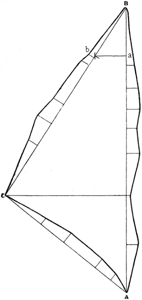
To lay down Fig. 82 in this manner, having fixed the first station A, the length of the first primary reference line A B may be laid off upon the meridian, because in this case the bearing being due north, the reference line will be coincident with the meridian. This done, the protractor is to be placed over the plotted point B and the second bearing laid down. Having plotted the length of this line in the point C, the third reference line C A will be determined both in length and direction by the plotted points C A, which should be joined and the line measured to ascertain whether its length corresponds with the measured distance. If these do not correspond, the angle must be replotted and the lengths laid off anew to discover the source of the error. Assuming, however, that the lines close properly, the offsets and other secondary points may be next plotted in the manner previously described.
Angles may be more accurately laid down by means of a table of natural sines and cosines and a linear scale than by means of a protractor. This is especially true when the angles are subtended by long lines, as, for example, lines of 3, 4, and even 6 feet. In such cases, a protractor is of little use. This mode of laying down angles is also convenient in some cases where angles have been taken, but some of the sides not measured. In using the table, it must be remembered that the radius of the sines and cosines is taken as unity; therefore, to find the sine and cosine for any other radius, the sine and cosine in the tables must be multiplied by that radius. To lay down the angle A B C in Fig. 82, the reduced cosine of the angle should be plotted from B in the point a, according to some scale. The scale length of the reduced sine should then be scribed from a, and the scale length of the radius scribed from B. A line drawn from B through the point of intersection of the scribes will lay down the angle corresponding to the sine and cosine in the table. Suppose the radius chosen to be 5 chains, the angle being 32° 30′. The cosine of 32° 30′ is ·8434, which multiplied by 5, the assumed radius, = 4·2170. Lay off this distance from B on the base A B. The sine of 32° 30′ is ·5373, which multiplied by 5, = 2·6865. From the point a, which is distant 4·2170 chains from B, with a radius equal to 2·6865 chains, describe an arc; and from the point B, with a radius equal to 5 chains, describe another arc. From B draw a line through the intersection of these arcs, and lay off upon it the measured length of 1946 links as recorded in the field-book.
If only the length of the base A B and the magnitudes of the angles A B C and B A C were given, the lengths of the sides B C and A C would have to be calculated by trigonometrical formulæ. This method of calculating the lengths of the sides of triangles and plotting them with the beam compasses, like chained triangles, is the most accurate for laying down the great or primary triangles of a survey.
When it is required to plot according to this principle a solitary angle, as, for example, that between a station line and the meridian, a circle should be drawn with as large a radius as practicable round the station at which the angle is to be laid down. The distance between the points at which the two lines enclosing the angle cut that circle is then found by multiplying the radius by the chord of the angle, that is, by twice the sine of half the angle.
It sometimes happens, particularly in extensive surveys, that all the angular points of some triangles cannot be plotted upon the same sheet of paper. In such cases, the plot of the outlying points and the sides of the triangles may be laid down in the following manner. Plot the intersected triangles independently and trace them on tracing paper. Then, having drawn a fine line upon both sheets to represent the sheet edge, lay the points on the trace corresponding to those already plotted on the first sheet down upon, and make them to coincide with, the latter. Secure the trace in this position and trace the sheet edge line upon it. The intersected lines may now be plotted on the fair sheet with a pricker at points outside the sheet edge line. Next apply the trace to the second sheet and make the sheet edge lines coincide. Having secured the trace in this position, the points and the intersected lines on this second sheet may be plotted upon the fair paper by means of the pricker.
To Plot Traverse Reference Lines.
—In plotting a traverse survey in which the angles have been measured from a fixed line of direction, the magnetic meridian, the direction of the lines may be all laid down at the first angular point. An example will best show the method employed in this case. It is required to lay down the traverse shown in Fig. 83.
Fig. 83.
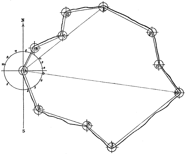
Larger illustration (75 kB).
In a convenient part of the paper draw the straight line N S to represent the magnetic meridian, and plot upon it the first station A. Set the protractor with its centre accurately placed over this point and its 360th and 180th divisions coinciding with the meridian. Holding the instrument securely in this position, lay off around it all the bearings as entered in the field-book, numbering them in the order in which they were taken. Against each of these numbers it is well to place the page of the field-book on which the measurement of the angle and the survey of the line are entered. The plotting must now be commenced by laying down the first line through the first bearing and determining its length from the recorded measurements. The direction of the second line has next to be transferred from the first station A to the extremity of the first line, or the second station B. This is accomplished by means of the parallel ruler, by placing the edge of the ruler through the plotted point and the point marked as bearing 2, and extending it till the same edge intersects the point B. A line is then to be drawn from this point and its length laid off from the field-book as before. The direction of the third line will then be transferred from the first angular point to the end of the second line, or station C, in the same manner. This will be continued for all the lines in the traverse, and if all the measurements have been correctly laid down, not only will the last line pass through the point A, but it will be of the same length as the chained line. Also the bearings taken from A to E and H will pass through these latter stations. These proof line bearings should be laid down at the same time as the reference line bearings, from which they should be distinguished by some sign. The directions of the reference lines should be consecutively transferred, and the length of each line should be plotted in its proper place before the direction of the next is transferred. To ensure the work closing properly, great care must be taken to plot the points accurately and to draw the pencil lines fine.
Fig. 84.
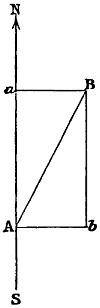
The degree of accuracy to be attained will depend in a great measure upon the extent of the traverse. With long lines the difficulties increase, and with a great number of angles the chances of error are multiplied. If the angles are carefully taken, it is probable that seconds have been read off in several instances, and these if neglected, especially upon long chain lines, may lead to an error of some importance. Also when the lines are long, the parallel ruler becomes practically useless, and some other system has to be adopted. One way of overcoming these difficulties is to draw a parallel to the first meridian through every third or fourth angle; in such a case, great care must be observed in drawing the parallels. A more easily practicable method, however, is to use the T-square in the manner already described. If the left-hand edge of the drawing board be made the north, the blade will determine meridional lines, and by laying the straight side of a semicircular protractor against the edge of the blade, its zero will be adjusted to the fixed line of direction. The first bearing having been laid down, the line is drawn and made the scale length of the chain line; the blade of the square is then pushed to the station thus found, and the next bearing set off. This operation is repeated until all the lines have been laid down. If the work closes properly, the plotting of the secondary lines may be proceeded with.
The most accurate method of plotting a traverse is by rectangular co-ordinates, or, as it is usually termed, Northings, Southings, Eastings, and Westings, because the position of each station is plotted independently, and is not affected by the errors committed in plotting previous stations. This method consists in assuming two fixed lines or axes crossing each other at right angles at a fixed point, computing the perpendicular distances or co-ordinates of each station from those two axes, and plotting the position of each station by means of the T and set squares and a linear scale. The meridian is usually made to represent one of the axes, and in this case the co-ordinates parallel to one axis will be the distances of the stations to the north or south of the fixed point, and those parallel to the other axis will be their distances to the east or west of the same point. Let N S, Fig. 84, represent the meridian, and A B the first bearing taken, and the first line measured. The angle in this case is N A B = θ. If θ is an acute angle, the second station B is to the north of the first station A; if it is an obtuse angle, B is to the south of A. If the angle θ lies to the right of the meridian, B is to the east of A; if to the left, to the west. Thus it will be seen that if the northernly and easternly directions are considered positive, the southernly and westernly directions will be negative. From the foregoing it is manifest that the co-ordinates of B are as follows:—
Northing A a = b B (or if negative, southing) = A B × cos. θ. Easting A b = a B (or if negative, westing) = A B × sin. θ.
To plot the point B, draw through the point A, with the aid of the T-square, a horizontal line. Multiply the chained length of the line A B by the sine of the angle N A B as entered in the field-book, and set off this distance along the horizontal line. From the point thus determined, erect, with the aid of the set square, a perpendicular, which will be parallel to the meridian. Multiply the chained length of A B by the cosine of the angle N A B, and set off this distance along the perpendicular line. The point thus determined will be the position of the second station B, which may then be joined to A by a straight line.
Fig. 85.
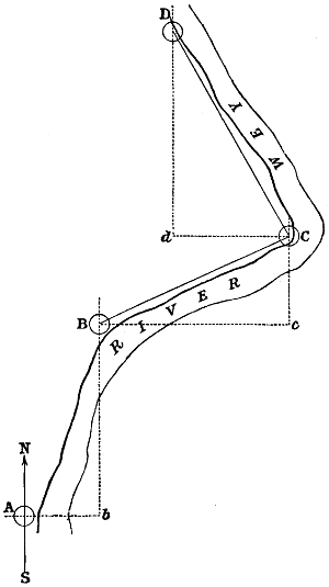
The mode of laying down the survey in Fig. 85 will now be obvious. Having determined the position of the second station B in the manner just described, draw a horizontal line through B and determine the third station C in the same way. The fourth station D being to the left of the meridian passing through C, c d is a westing and is to be considered as negative. Therefore the horizontal line through C must be drawn to the left of that station, and the station D determined in the same manner as the preceding stations.
The results of all these calculations should be entered in a book, in four columns, for northings, southings, eastings and westings respectively. Also in four other columns should be entered the total northing or southing, and easting or westing, of each station from the first station, computed by adding all the successive northings and subtracting the southings made in traversing to the station, the result being a northing if positive, and a southing if negative. The same treatment is applied to the eastings and westings. This affords a means of testing the accuracy of the work. It is also obvious that the position of the last or any station may be determined by this means without plotting the intermediate stations.
Let it be observed that both θ and sin. θ are positive or negative according as that angle lies to the east or to the west of the meridian; and that the cosines of obtuse angles are negative.
To Plot Detail.
—By “detail” is meant outlines or objects whether natural or artificial, such as fences, walls, rivers, canals, roads, lakes, water margins, beach marks, seas, or imaginary boundary lines. In plotting from the entries of measurements for detail, these measurements should be laid down upon the paper in the order and manner indicated in the field-book. The mode of plotting the perpendicular reference lines by means of which the position of the detail is fixed has already been fully described and illustrated. The proper connections for detail, as shown by the field-book, should be made by drawing a firm pencil line through the detail points with the aid of an offset scale adjusted successively to the adjacent points. All such connections should be clearly and elegantly made. When all boundaries, roads, and streams have been drawn and inked in, tracings should be taken in small portions of all that has been laid down for the use of the “examiner.” The duties of the examiner are to make on the ground the necessary corrections for omissions and detail in error; to give, in position and character, woods, water, marsh, commons, vegetable and geological features, and permanent artificial structures; and to furnish the descriptive names of places and things, or any other desirable information. The topographical character of mountains, marshes, bogs, rough pasture, woods and water, should be drawn in character on trace and tinted. If required, hill sketching should also be supplied on the examiner’s trace. On being returned to the office, the plotter should replot from the field notes the detail corrected, and transfer the details from the trace to the map.
To Plot Contours.
—The student who has made himself familiar with the methods of laying down angles, and plotting reference lines and points, will find no difficulty in laying down contour traces. When the contour points have been surveyed with the chain, the contour is obtained by drawing a free line of feature through the plotted points. But when the contour points have been surveyed by measuring magnetic angles to known points, such angles must be laid down at these points, and produced to meet in the contour point. The drawing of contours differs from the drawing of ordinary detail insomuch as each contour point is shown by a small dot, and each carrying point by a similar dot surrounded by a small hand-drawn circle to distinguish it. The former should be so plotted as to be distinguishable in the trace or contour line, which should be readily traceable, but not conspicuous. The line joining adjacent points should be true lines of feature. Colour is usually employed for these lines, and it is well to give them a broken or somewhat undefined character. When the French system is adopted, contour lines are drawn continuous, a broad but faint line of colour.
To Plot Sounded Points in Submerged Districts.
—When the angles have been measured on dry land with the theodolite, these angles should be laid down at the dry-land points, and the lines produced to meet in the sounded point. But when the angles have been measured on the water with a sextant, a station pointer is required. The arcs of the pointer should be adjusted to read the measured angles, and the instrument applied to the plotted points of the observed objects so as to bring the hair lines accurately to their respective object points. The sounded point may then be correctly plotted through the centre of the pointer. If the angles have been measured by the magnetic compass, that is, if the angles are those made with the magnetic meridian, the angles should be laid down at the plotted points of the observed land objects, and the lines produced to meet in the sounded point. Instead of the station pointer, a piece of tracing paper may be used in the following manner. Draw three straight lines radiating from one point so as to make with each other angles equal to the measured angles. Lay the paper on the plan and move it about till the three lines traverse the observed objects. The point from which they diverge will then mark the position of the sounded point, which may be plotted by being pricked off.
The sounded point determined by angles measured with the sextant may also be plotted by describing circles on the land-object lines as chords, to contain segmental angles equal to the measured angles. Such circles will intersect in the common land-object point and the sounded point. To plot the sounded point in this manner, requires the solution by construction of the problem, “to describe on a given line a segment of a circle that shall contain a given angle.” But this method is generally found too tedious in practice.
Errors and Error-sheets.
—There is a tendency, as we have previously remarked, for the measured lengths of lines to be a little too long, by reason of the irregularities of the surface. It is usual to allow for this source of error 1 in 1000 in fair open country, and 11⁄2 in 1000 in close country. When the measurements differ by an amount exceeding these limits, the pencil trace should not be drawn between the reference points, but the line should be entered on an “office error-sheet.” The error-sheet should show the number of the plot-sheet, the triangle, the book and page in which the measurements are entered, and the scale and measured lengths of the line. To ascertain the source of the error, other lines referenced to the reference point or points of the line in error should be plotted, and the apparent source should be entered on the error-sheet. If the lines referred to the same point be found to plot to another point in the reference line, the scale measurement of this point should also be entered. And if the reference point in error be not directly surveyed in the survey of their respective lines, the measurements for reference and the arithmetical reductions will have to be examined. Besides the office error-sheet, there should be a field error-sheet for each book and triangle, upon which should be entered the book, the page, and the line in error, and some indication of the source of the error. This sheet will be forwarded with the field-book to the surveyor for correction. The following are examples of a common and very good form of error-sheet, but it may be varied in many ways if thought desirable:—
Office Error-sheet.
Plotter’s Name Date
Book. Lines. Scale Measurement. Reference Points of Lines. Apparent Corrections. Triangles. Observations.
Page.
200 1953 1907 1118 1551 1651 Examine reference point and line.
23 2094 4020 4020
200 3000 3056 2814 1308 3056 Examine line.
28 4020 3082
200 1314 1323 1551 85 1651 Examine reference point and line.
42 4020 3028 4020
Field Error-sheet.
To A. B., Surveyor. Date
Book. Lines. Triangles. Observations.
Page.
Examine reference points and line.
200 1953 1651 Reference point (August 10th, 1874).
23 4020
200 3000 Examine line. Line 3056 (August 10th, 1874).
28
Examine reference points and line.
200 1314 1651 (August 12th, 1874).
42 4020
Corrected in the field, A. B.
To Plot Vertical Sections.
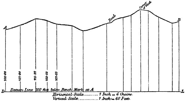
—In plotting a vertical section, a fine and firm horizontal line is first drawn to represent the datum line. The reference points are then plotted upon this line from the level-book by means of a linear scale, in the manner already described for plotting such points. The reference points to be plotted upon the datum line are the chain lengths entered in the field-book in the column headed Distances. These distances are the points at which the levels were taken, and between them, unless otherwise stated in the field-book, the ground is supposed to slope uniformly. Moreover, these distances are assumed to be measured horizontally, and therefore care must be taken to ascertain whether or not they were so measured in the field; if not, they must be reduced before plotting, or the section will be too long. Having plotted the reference points on the datum line, a perpendicular must be erected from each of them, and a length laid off upon this perpendicular equal to the vertical height above the datum line indicated by the entry in the column of the level-book headed Reduced Levels against the distance to which the perpendicular corresponds. To render the differences of altitude more apparent, these vertical distances are plotted to a much larger scale than the horizontal, as explained in a preceding Section. To erect the perpendiculars, the T and set square furnish the most convenient means. The detail points thus determined upon the perpendiculars represent the points in the surface of the ground at which the levels were taken, and by joining these points we obtain the surface line. An example will clearly show the method pursued. Let it be required to lay down the section from the following level-book:—
Back Sights. Fore Sights. Rise. Fall. Re- duced Levels. Dis- tances. Remarks.
feet. feet. feet. feet. feet. chains.
100·00 .. B.M. north-west corner of church tower.
16·41 9·37 7·04 .. 107·04 230
19·36 10·43 8·93 .. 115·97 465
16·42 19·36 .. 2·94 113·03 640
8·36 14·36 .. 6·00 107·03 794
9·37 12·49 .. 3·12 103·91 1030
11·64 19·76 .. 8·12 95·79 1200
19·46 9·32 10·14 .. 105·93 1564
17·64 13·62 4·02 .. 109·95 .. Centre of road at 123 links.
18·76 12·64 6·12 .. 116·07 1823
19·84 16·92 2·92 .. 118·99 1964
19·76 11·64 8·12 .. 127·11 2100 Forward station ☉ at corner of wood.
17·64 19·72 .. 2·08 125·03 2250
9·73 18·64 .. 8·91 116·12 2376
8·64 17·64 .. 9·00 107·12 2590
18·76 16·24 2·52 .. 109·64 2700
231·79 222·15 49·81 40·17
222·15 40·17 100·00
9·64 9·64 9·64 Difference between datum and last reduced level, or height of B above A.
Fig. 86.
Larger illustration (54 kB).
Draw the datum line D L, Fig. 86, and set off along it the distances 230, 465, 640, 794, &c., links; these points will be the reference points for the perpendiculars. Erect a perpendicular from each of these points, and lay off, to a suitable scale, upon these lines successively the vertical heights 100, 107·04, 115·97, 113·03, 107·03, &c. The points thus determined will be the surface detail points, and by joining these we shall obtain the surface line. Then will A D L B represent a section of the ground between A and B. A description of objects on the surface worthy of notice should be written over such objects.
In working sections, where great accuracy is required, larger scales are employed, and the levels are taken at more frequent intervals. Thus, in a railway working section, for example, the levels are taken at every chain’s length, and also over every little undulation in the surface of the ground. In preparing such sections, vertical lines are drawn in blue at every chain’s length up to the surface of the ground from the datum line, and on each vertical is written the reduced height above datum from the column of reduced levels in the level-book.
Sections, especially working sections, are usually drawn upon ruled, or, as it is called, “section” paper, the nature of which we have already described. This method, which was introduced by Mr. Brunel, possesses many practical advantages, inasmuch as it obviates the necessity of plotting the “distances” and erecting perpendiculars, the latter already existing. It also greatly facilitates the computation of the contents of a given section. Its chief defect lies in the difficulty of making the horizontal lines coincide when joining the sheets end to end. Of course scales are not required upon section paper.
To lay down Gradients.
—The method of laying down the gradients of railways and roads usually adopted in practice consists in applying one end of an extended silken thread to the section at the point in which the road commences, and the other end in such a position that the thread may cut the profile of the earth’s surface so as to leave equal portions of space above and below the thread, as nearly as can be judged by the eye. The cuttings from the parts above the thread will then furnish sufficient materials to form the embankments in the spaces below. This is called “balancing” the cuttings and embankments. When the first gradient has been determined in this way, it may be found unfavourable to the second in respect to the extent of cuttings and embankments; in such a case it must be modified to suit the requirements of the latter. In this way the gradients must be modified successively until the compound result evidently gives a minimum of cuttings and embankments, due regard, of course, being had to the limits imposed by the nature of the case, both with respect to the ruling gradient and the proper heights for bridges.
To Plot a Section from a Contour Map.
—The mode of plotting a section from a contoured plan was explained when treating of contour lines. The contour map used for this purpose should give the features of the surface configuration in sufficient detail without serious error. Having drawn a line of section on the map and a datum line upon the fair paper for the vertical section, the points in which the section line intersects the contours should be measured on the scale of the map from a zero point in that line, and the measurements plotted upon the datum line. Perpendiculars should then be drawn through these plotted points, and on these perpendiculars the reduced altitudes of their respective contour points should be plotted. A line drawn through these surface plotted points will be the surface line. When the horizontal scales of the map and the section are the same, the contour plane lines may be drawn on the paper for the section parallel to the section line on the map, and perpendiculars raised to intersect them from the points on the map in which the section line intersects the contours, in the manner previously described. The points of intersection with the parallel lines will be the surface contour points in the vertical section. For practical purposes, the parallel lines and the perpendiculars are only temporarily drawn in pencil until the surface trace shall have been obtained and drawn in ink, with the datum line.
Section IV.—Civil Engineers’ and Surveyors’ Plans.
In the preceding Sections the manner of laying down plans has been fully described and the principles involved in the operations minutely explained. It now only remains, therefore, to direct attention to certain matters relating to the preparation of plans, which are necessitated by the circumstances of particular cases.
Civil engineers’ plans usually consist, if we except harbour surveys, of a representation, to a rather large scale, of long and narrow tracts of country through which it is proposed to construct a means of communication, such as a railway, a road, or a canal. They do not differ essentially from other plans, the survey being taken in the ordinary way, and the plan laid down according to one or other of the methods described in the preceding Section. The width of railway surveys varies from five to twenty chains, at the option of the engineer. An important matter demanding careful attention is to survey, plot, and number all fields and other enclosures, houses and other buildings situate within the limits of deviation, that is, the boundaries of the space beyond which it is not proposed to deviate the line of railway. The object of numbering every separate enclosure, road, building, or other object on the plan, is that they may be the more readily described in a book prepared for that purpose and called the Reference Book. Parish and county boundaries are shown by dotted lines, as explained in a former Section. Frequently it is necessary, in consequence of the smallness of the scale adopted for the plan, to give enlarged drawings of certain portions. In these cases, whenever practicable, the enlarged plan should be placed directly under or over the small plan to which it refers, as such an arrangement is not only more pleasing to the eye, but is far more convenient for reference than one in which there is no relation of position between the two plans. The proposed railway should be represented by a full and heavy line, and the limits of deviation shown by strong dotted lines. The names of the different parishes through which the line passes should be conspicuously written, and the name of the county placed at the top of each sheet; the sheets also should be distinctly numbered. It is not usual to distinguish different kinds of fences on plans of engineering projects, as on estate plans to a large scale; on the former it is sufficient to distinguish between fenced and unfenced lines of division of land, marking the former by plain, and the latter by dotted lines. It is almost needless to remark that a scale of distances should accompany every plan.
The section should be drawn to the same horizontal scale as the plan, and the exaggeration of the vertical scale should be such as to show distinctly the irregularities of the surface. The horizontal datum line of the section should have marked on it a scale of distances corresponding with those marked along the centre line of the plan, in order that corresponding points on the plan and the section may be readily found, and great care should be taken that horizontal distances on the plan and on the section exactly agree. Cross sections are longitudinal sections of existing lines of communication which the proposed work will cross; they may cross the centre line of the proposed work either at right angles or obliquely. Cross sections may also be required where the ground slopes sideways; in general they should be ranged accurately at right angles to the centre line, and they should be plotted without exaggeration, that is, their vertical and horizontal scales should be the same as the vertical scale of the longitudinal section. All cross sections should be plotted as seen by looking forward towards them along the centre line.
To distinguish the nature of the soils passed through, sections are frequently coloured, as shown in Plate 21. The information given by this means concerning the character of the strata is of very great value to the engineer or to the contractor, inasmuch as it enables them to predicate with some degree of certainty the amount of labour that will be required in executing the proposed work. It is, therefore, highly important that the draughtsman correctly represent the character of the strata. The conventional modes of representing these features are shown on Plate 20, which should be carefully studied and copied.
It is necessary that the engineering draughtsman should be acquainted with the “Standing Orders” of Parliament relating to the preparation of plans and sections, in order that he may fulfil the conditions therein laid down. And as most of the important details involved by the exigencies of practice in the preparation of such plans and sections are prescribed by these Standing Orders, we will give so much of them as relates directly to the matters under consideration; by so doing, the details will be clearly and fully described, and the requirements of the law concerning them authoritatively made known.
Nature of the Documents required.
—“In cases of bills relating to engineering works, a plan and also a duplicate thereof, together with a book of reference thereto, and a section and also a duplicate thereof, as hereinafter described, shall be deposited for public inspection at the office of the clerk of the peace for every county, riding or division in England or Ireland, or in the office of the principal sheriff clerk of every county in Scotland, and where any county in Scotland is divided into districts or divisions, then also in the office of the principal sheriff clerk in or for each district or division in or through which the work is proposed to be made, maintained, varied, extended or enlarged, or in which such lands or houses are situate, on or before the 30th day of November immediately preceding the application for the bill.”
“In the case of railway bills, the ordnance map, on the scale of one inch to a mile, or where there is no ordnance map, a published map, to a scale of not less than half an inch to a mile, or in Ireland, to a scale of not less than a quarter of an inch to a mile, with the line of railway delineated thereon, so as to show its general course and direction, shall, on or before the 30th day of November, be deposited at the office of the clerk of the peace, or sheriff clerk, together with the plans, sections, and book of reference.”
“In cases where the work shall be situate on tidal lands within the ordinary spring tides, a copy of the plans and sections shall, on or before the 30th day of November, be deposited at the office of the Harbour Department, Board of Trade, marked ‘Tidal Waters,’ and on such copy all tidal waters shall be coloured blue, and if the plans include any bridge across tidal waters the dimensions as regards span and headway of the nearest bridge, if any, above and below the proposed new bridge, shall be marked thereon, and in all such cases such plans and sections shall be accompanied by a published map or ordnance sheet of the country, over which the works are proposed to extend, or are to be carried, with their position and extent, or route accurately laid down thereon.”
“In the case of railway bills, a copy of all plans, sections, and books of reference, and the aforementioned published map with the line of railway delineated thereon so as to show its general course and direction, is required to be deposited at the office of the Board of Trade, and at the Private Bill Office of the Houses of Parliament; and in cases where any portion of the work is situate within the limits of the Metropolis, a copy of so much of the plans and sections as relates to such portion of the work is required to be deposited at the office of the Metropolitan Board of Works. Also a copy of so much of the plans and sections as relates to each parish in or through which the work is intended to be made, or in which any lands or houses intended to be taken are situate, together with a copy of so much of the book of reference as relates to such parish, is required to be deposited with the parish clerk of each such parish in England, with the school-master of each such parish in Scotland, and with the clerk of the union within which such parish is included in Ireland.”
Plans.
—“Every plan required to be deposited shall be drawn to a scale of not less than four inches to a mile, and shall describe the line or situation of the whole of the work (no alternative line or work being in any case permitted), and the lands in or through which it is to be made, maintained, varied, extended or enlarged, or through which every communication to or from the work shall be made; and where it is the intention of the parties to apply for powers to make any lateral deviation from the line of the proposed work, the limits of such deviation shall be defined upon the plan, and all lands included within such limits shall be marked thereon; and unless the whole of such plan shall be upon a scale of not less than a quarter of an inch to every one hundred feet, an enlarged plan shall be added of any buildings, yard, courtyard or land within the curtilage of any building, or of any ground cultivated as a garden, either in the line of the proposed work or included within the limits of the said deviation, upon a scale of not less than a quarter of an inch to every one hundred feet.”
“In all cases where it is proposed to make, vary, extend or enlarge any cut, canal, reservoir, aqueduct or navigation, the plan shall describe the brooks and streams to be directly diverted into such intended cut, canal, reservoir, aqueduct or navigation, or into any variation, extension or enlargement thereof respectively, for supplying the same with water.”
“In all cases where it is proposed to make, vary, extend or enlarge any railway, the plan shall exhibit thereon the distances in miles and furlongs from one of the termini; and a memorandum of the radius of every curve not exceeding one mile in length shall be noted on the plan in furlongs and chains; and where tunnelling as a substitute for open cutting is intended, such tunnelling shall be marked by a dotted line on the plan.”
“If it is intended to divert, widen or narrow any turnpike road, public carriage road, navigable river, canal or railway, the course of such diversion, and the extent of such widening or narrowing shall be marked upon the plan.”
“When a railway is intended to form a junction with an existing or authorized line of railway, the course of such existing or authorized line of railway shall be shown on the deposited plan for a distance of eight hundred yards on either side of the proposed junction, on a scale of not less than four inches to a mile.”
Book of Reference.
—“The book of reference to every such plan shall contain the names of the owners or reputed owners, lessees or reputed lessees, and occupiers of all lands and houses in the line of the proposed work, or within the limits of deviation as defined upon the plan, and shall describe such lands and houses respectively.”
Sections.
—“The section shall be drawn to the same horizontal scale as the plan, and to a vertical scale of not less than one inch to every one hundred feet, and shall show the surface of the ground marked on the plan, the intended level of the proposed work, the height of every embankment and the depth of every cutting, and a datum horizontal line, which shall be the same throughout the whole length of the work, or any branch thereof respectively, and shall be referred to some fixed point (stated in writing on the section), near some portion of such work, and in the case of a canal, cut, navigation, turnpike or other carriage road or railway, near either of the termini.”
“In cases of bills for improving the navigation of any river, there shall be a section which shall specify the levels of both banks of such river; and where any alteration is intended to be made therein, it shall describe the same by feet and inches, or decimal parts of a foot.”
“In every section of a railway, the line of the railway marked thereon shall correspond with the upper surface of the rails.”
“Distances on the datum line shall be marked in miles and furlongs, to correspond with those on the plan; a vertical measure from the datum line to the line of the railway shall be marked in feet and inches, or decimal parts of a foot, at each change of the gradient or inclination; and the proportion or rate of inclination between each such change shall also be marked.”
“Wherever the line of the railway is intended to cross any turnpike road, public carriage road, navigable river, canal or railway, the height of the railway over or depth under the surface thereof, and the height and span of every arch of all bridges and viaducts by which the railway will be carried over the same, shall be marked in figures at every crossing thereof; and where the roadway will be carried across any such turnpike road, public carriage road or railway, on the level thereof, such crossing shall be so described on the section; and it shall also be stated if such level will be unaltered.”
“If any alterations be intended in the water level of any canal, or in the level or rate of inclination of any turnpike road, public carriage road or railway, which will be crossed by the line of railway, then the same shall be stated on the said section, and each alteration shall be numbered; and cross sections in reference to the said numbers, on a horizontal scale of not less than one inch to every three hundred and thirty feet, and on a vertical scale of not less than one inch to every forty feet, shall be added, which shall show the present surface of such canal, road or railway, and the intended surface thereof when altered; and the greatest of the present and intended rates of inclination of such road or railway shall also be marked in figures thereon; and where any public carriage road is crossed on the level, a cross section of such road shall also be added; and all such cross sections shall extend for two hundred yards on each side of the centre line of the railway.”
“Wherever the extreme height of any embankment, or the extreme depth of any cutting, shall exceed five feet, the extreme height over or depth under the surface of the ground shall be marked in figures upon the section; and if any bridge or viaduct of more than three arches shall intervene in any embankment, or if any tunnel shall intervene in any cutting, the extreme height or depth shall be marked in figures on each of the parts into which such embankment or cutting shall be divided by such bridge, viaduct or tunnel.”
“Where tunnelling, as a substitute for open cutting, or a viaduct as a substitute for solid embankment, is intended, the same shall be marked on the section.”
“When a railway is intended to form a junction with an existing or authorized line of railway, the gradient of such existing or authorized line of railway shall be shown on the deposited section, and in connection therewith, and on the same scale as the general section, for a distance of eight hundred yards on either side of the point of junction.”
Besides the information thus written on the plan, it is useful to the engineer, though not prescribed, to have the levels of important points either written or shown by means of contour lines, especially when the plan is to be used in selecting a line of railway. The results of trial pits and borings may also be written on the plan, and the estimated cost of each part of the work placed opposite to its position on the paper.
Working Sections.
—For working sections the horizontal scale adopted is usually three or four chains to the inch, and the vertical scale 30 or 40 feet to the inch. A working section should show the level of the ground, the level of the proposed work, and the height of embankment or depth of cutting at every point of the ground where the level has been taken, these quantities being found by calculation, not by measurement on the paper. The position and levels of all “bench marks” should also be clearly indicated. At every crossing of road, river or stream of any kind, should be inserted some remark respecting the work to be constructed, with a reference to the number of the working drawing prepared. The latter may be a special drawing, as for a bridge, or a general drawing, as for a level crossing and gates. The results of boring should also be shown on the working section. As soon as the works of construction have been determined upon, notes should be inserted from the working drawings, or other sources, of the angles of skew at which the line crosses roads or streams, the spans of arches on the square and on the skew, the rise of the arch, the depth of the arch stones, and of the puddle, if any be used, and, if the works be on an inclined plane, the rise or fall from centre to centre of the piers. Similar memoranda should also be made of girder bridges, culverts, and other works occurring along the line. To all working drawings the acting engineer always affixes his signature.
Besides an acquaintance with the “Standing Orders,” the engineering and surveyor’s draughtsman should possess a knowledge of the Regulations of the Local Government Board, for these have to be complied with in the preparation of plans relative to main sewerage, drainage, and water-supply. These Regulations are as follows.
Boundary Maps.
—In cases in which a special district is proposed to be formed for the adoption of the Local Government Act, a map must be submitted, accompanied by a written description of the proposed boundary, designated by letters from point to point, commencing from a fully and clearly defined point on the north side of the map marked by the letter A and a written description, then proceeding eastward by natural or other well-defined features, until the description closes upon the point started from. The name of the proposed district must be printed on the map, with the area in acres. The population and the number of houses, with the rate of increase as ascertained at the two last decennial periods upon which the census was taken, must be given, and a duplicate or tracing of the map furnished.
Maps for Division into Wards.
—A map of the entire district must, in this case, be submitted, with the main boundary distinctly defined, and the name of the district clearly printed thereon. The proposed division into wards must be by lines, clearly defined on the map of the district; brooks, roads, footwalks, streets, fences, or other easily recognizable lines of division may be adopted. Such lines must be defined on the map by a margin of colour. The proposed boundary-lines must be described in the same manner as in the boundary map, and the name or number of the ward, with the relative areas, population, and rateable value must be given. A duplicate map or a tracing must be deposited at the Local Government Act Office for future reference.
Plans of Proposed Works.
—It is in all cases necessary, upon application being made by Local Boards for the Secretary of State’s sanction to a loan for the execution of works, that plans, sections, detailed estimates, and specifications be submitted with the application, accompanied with the information relative to area, population, number of houses, and rateable value of the district required for boundary maps. Tracings of such plans and sections, and copies of the estimates and specifications must be sent in for filing at the Local Government Act Office.
General Plan.
—A general plan exhibiting the area which will be affected by the proposed works must be laid down to a scale of not less than two feet to a mile. It should have figured upon it the levels of the centres of all the streets and roads at their intersections and angles, and at every change of inclination; also, where a district is near the sea, it should show the high and the low tide level of the sea, and where there is a river, the summer and the flood-water levels should be recorded. Permanent bench marks having reference to the surface levels should be cut on public buildings, or other permanent and suitable objects, throughout the district, and clearly marked on the plan. Sections should accompany this plan, upon which the levels of the cellars should be shown. Such a plan may be used for showing the lines of main-sewers and drains, lines of water-pipes, and gas-mains. The lines of main-sewers and drains should have the cross-sectional dimensions and the gradients distinctly marked upon them. The dimensions of water and gas pipes should also be shown in figures or in writing.
Detailed Plan.
—A detailed plan for the purposes of house-drainage, paving, the sale and purchase of property, or other purposes of a like character, must be constructed to a scale of not less than ten feet to a mile. Upon this plan must be exhibited all houses and other buildings, bench marks, the levels of streets and roads, of cellars, of the sea at high and low tide level, and the summer and the flood level of rivers. Three feet by two feet will be a convenient size for the sheets of this plan, and by representing the marginal lines of the sheets upon the general plan, and numbering the sheets to correspond, the general plan will become a very useful index.
As it may occasionally be desired to carry out works piecemeal, with a view to save the time which would be occupied in the preparation of a complete plan from actual survey, it is sufficient in the first instance to furnish a general plan of streets and roads only, with the surface levels and those of the deepest cellars, and the proposed scheme of works shown thereon, after which the works can proceed in sections. But with each separate application for sanction to a loan, a correct plan and section or sections should be submitted, accompanied by detailed estimates and specifications. It must, however, be understood that the complete plan of the entire district must be proceeded with, so that, when the works are finished, the Local Board and the office of the Local Government Act may possess a proper record.
Mining Plans.
—The plotting of mining surveys is performed in the same manner as the surface traverse surveys already described. Before proceeding to lay down the plan, it is well to divide the paper into squares of 10 chains side, or 10 acres area, by two sets of lines crossing each other at right angles, one of which sets should represent meridians. This operation should be performed with scrupulous care; and to ensure accuracy, beam compasses should be used to lay off the divisions. The lines should be finely drawn in colour to distinguish them from other lines to be put upon the drawing. Care must be taken to get the plan fairly upon the paper, so that the conformation of the outline or boundary to the edges of the paper may have a pleasing effect to the eye; and the direction of the meridians must be determined according to this condition. By having the plan thus divided into squares of 10 acres each, the quantity of ground worked out may be approximatively estimated at any time by inspection, and the total quantity may be readily computed in the same manner. Besides dividing the plan itself in this way, it will be found extremely useful to have a sheet of tracing paper, or better, tracing cloth, divided into squares of 316·228 links side, or 1 acre area, in black lines; each of such squares being subdivided into 4 by lines in colour, to show quarters of an acre. To find the area of any portion of exhausted or of unworked ground, it is only necessary to lay this divided sheet over such portion and to count the squares and quarters included in it.
By reason of the variations of the magnetic meridian, the date of a survey should always be written on the plan; and as the plan of underground workings is laid down piecemeal as the workings progress, often extending over a period of many years, care must be taken to reduce all bearings to the original meridian. Unless these matters are strictly observed, serious errors may result.
When two or more veins of mineral are being worked one above the other, and are placed upon the same plan, they are distinguished by means of colour. It matters not what colours are employed for the several separate workings so long as they are distinct from each other. Also the mode of applying the colour, whether with the brush or with the pen, is entirely a question of taste. It may, however, be observed that as mining plans are constantly being added to, it is very difficult to avoid a patchy appearance when the colour is laid on with the brush. Plate 33 shows the manner in which mining plans are got up.
Estate and Town Plans.
—Plans of estates and towns, including as they do only a limited area and requiring great distinctness of detail, are laid down to a large scale; for the form and character of the detail are, on such plans, of equal importance with its position. With such a scale as is required in these cases, it is possible, not only to clearly distinguish natural and artificial features, but to introduce means of producing pictorial effect into their representation. The nature of these means may be seen in the examples of plans appended to this work.
The manner of showing the various kinds of fences has been already described. Trees are usually shown in elevation for the sake of artistic effect; but care must be taken to give them such dimensions as will accord with the scale of the drawing. Houses and other buildings are shown in plan of the correct form, and washed for distinction in light red for dwelling-houses, dark grey for outhouses, and light grey for public buildings. Dark grey is also used for all wooden and iron buildings to distinguish them from those constructed of the ordinary materials, brick and stone. But besides such distinctions, others are needed to indicate the character of natural features and artificial constructions. These are obtained either by showing the object roughly in elevation, or by some purely conventional means. The signs of this character that are likely to be frequently required on estate plans are shown on Plate 15. The manner of representing water, which has been described in a preceding Section, will be found illustrated in detail on Plate 11. Plates 10 and 14 show various kinds of trees; in this form they may be introduced very effectively into plans of estates.
The several stages which a plan passes through in the office are shown on Plate 2. If the plan is to be coloured, the colouring must be done before the lettering is put on. Plate 3 shows a plan lightly coloured, as used by surveyors, solicitors, and others; and Plate 17 shows a finished plan in colour. The methods of laying on the colours and the principles involved in the operations have been fully described and explained in a former Section. In Plate 13 is given a town plan showing a proposed street improvement. Such a plan must be laid down to a large scale, and the details in and near the part affected must be drawn in clearly and accurately. The uncoloured portion represents the plan as prepared for lithographing. When pink colour is used to show the proposed street, the buildings should be coloured in black by a light wash of Indian ink. Yellow or any other bright tint may be used for the proposed street, the object being merely to distinguish it clearly. Existing streets should be coloured in yellow ochre, except when that colour is used for the proposed street, in which case burnt sienna may be used.
The Plates relating to this Section are Nos. 2, 3, 10, 11, 13, 14, 15, 17, 19, 20, 21, and 33.
Section V.—Map Drawing.
The principles and practice of map drawing, being in the main identical with those of ordinary plan drawing, have been generally explained and described in the preceding Sections. In the present Section, therefore, we have only to direct attention to such details as belong especially to the former class of topographical representations. These details relate chiefly to the selecting of objects and features on the surface of the ground whose character entitles them to special notice, and therefore to distinct delineation; to the practical methods of sketching such objects and features in the field, and to the means and the manner of reproducing them on the finished map. The first and the last of these questions have been treated by Mr. James in his Handbook of Topography, and the second by Lieut. R. S. Smith of the United States’ Army, in so concise and yet so complete a manner that we have not hesitated to avail ourselves of their labours rather than attempt to offer any instructions of our own. The following is, therefore, worthy of respectful attention.
Single Stroke Streams.
—In inking in streams, begin at the source and draw downwards towards yourself, increasing the pressure on the pen as you descend. The use of the steel pen in drawing single stroke streams is very objectionable. Even soft steel pens are apt to cut the surface of the paper, and in sharp bends it is quite impossible to ensure an even width of line with the best yet made; by re-inking, much time is lost, and frequently a rough jagged line is the result. The common quill pen finely pointed will work well on any sort of paper.
Double Line Streams and Rivers.
—In maps of a small scale from 8 to 32 miles to the inch, it is usual to darken the north-western bank, supposing the light to fall from the N.W. corner of the map; but on maps of a large scale it is usual to attend strictly to the height of the banks, and the draughtsman should carefully represent the exact nature of each bank on his field-sketch or plane-table sheet.