PART I.—THE ESSENTIAL ELEMENTS.
Reading edition

Section I.—The Drawing Office and its Furnishings.
There are few occupations so dependent for their correct performance upon minute matters of detail as that of the draughtsman. Things apparently the most trivial are sufficient to render inaccurate or to mar the appearance of the otherwise most carefully and skilfully executed design, and as the value of a drawing depends wholly upon its accuracy and its appearance, it is obvious that such matters of detail, however trivial they may be in themselves, demand careful attention. We have, therefore, deemed it desirable to preface our remarks on Plan and Map Drawing with a brief description of the instruments and materials required, and of the mode of using them which experience has shown to be the best.
The Drawing Office.
—The first essentials of a room for drawing in are—that it shall be quite free from damp and be well lighted. The position of the windows is a matter of some importance, and though persons have largely to accommodate themselves to circumstances in this respect, it is desirable to know what are the most suitable conditions, in order that they may be complied with as far as circumstances permit. Skylights are unsuitable, because the light entering from above is liable to be intercepted by the body, and especially by the hands of the draughtsman; besides which, the light from a skylight is seldom sufficient. For the same reasons, a window placed very high in the room is objectionable. When possible, a western aspect is to be preferred, as the light from this direction is less variable and lasts later in the day than from other directions. Blinds of some kind are necessary to modify the light when the sun shines directly upon the window. Gaslights should be situate about 3 feet above the drawing table, and there should be two burners, placed not less than 2 feet apart, as otherwise the hands and the instruments will cast shadows which will prevent fine lines and points from being seen.
The drawing table should be placed under the window; it should have a breadth of about 2 feet 6 inches, and its height should be 3 feet 8 inches at the back and 3 feet 6 inches at the front. The front edge should be rounded over.
Dusters and means for washing the hands must also be provided, as it is requisite to frequently dust the paper and the instruments, and to keep the hands perfectly clean.
Instruments.
—All drawing instruments should be of the best workmanship, for it is impossible to obtain accuracy with imperfect tools, and they must be kept in order by careful handling. For all kinds of drawing, compasses of three sizes are required, the ordinary compass, the bows, and the spring bows. The best compasses are those which are sector-jointed. The points should be kept sufficiently sharp not to slip on the paper, but not so sharp as to readily penetrate it. It is also important that the points be thin and round, as otherwise, when several arcs have to be struck from the same centre, the compass leg is apt to make a large hole, which is utterly destructive of accuracy. The pencil leg should be kept exactly equal in length to the steel leg, for true circles cannot be drawn when one leg is shorter than the other. In removing the movable leg, care should be taken to draw it straight out, as nothing spoils the instrument so soon as wrenching the leg from side to side. In using the compasses, the instrument should be held lightly between the thumb and the forefinger only. It should not be pressed upon the paper; but it should rest equally upon both points. If the weight of the hand be thrown upon the instrument the points will penetrate the paper. Care should also be taken to bend the joints so as to keep both legs perpendicular to the paper. If attention be not given to this matter, the steel leg will make a large hole in the paper, and the ink leg will make a ragged line, because only one of the nibs will touch.
Next in importance to the compass, and of more frequent use, is the drawing pen. The draughtsman should possess at least two of these instruments, one for fine, and another for medium lines. When the proper opening of the nibs for fine lines has once been obtained, it is desirable not to change it; the pen can always be cleaned by passing a piece of drawing paper between the nibs. The cleaning of the pen should be carefully attended to; it should never be put away without having every particle of dried ink removed from it; and frequently, while in use, it should be wiped out to remove the dust, which is constantly settling in it, as well as the particles of lead that are taken up from the paper. The ink is supplied by breathing between the nibs and dipping them in the liquid, or by means of a camel’s hair brush. When the latter method is adopted, care should be taken to protect the brush from the dust floating in the atmosphere of the room.
After considerable wear, the drawing pen will require setting. The operation of setting requires some judgment and considerable practice, and is one of those mechanical niceties which it is difficult to describe. Generally it will be found advantageous to have the pen set by an instrument maker. As, however, this resource is not always at hand, it is desirable that the draughtsman should be able to set his own pen. The following description of the operation given by W. Binns, in his admirable work on Projection, is the best we have seen. “The nibs must be precisely of the same length, rounded in two directions, and as sharp as it is possible to make them without producing to the touch a sensation of cutting, and without scratching the surface of the paper when drawing a line, which is generally the case when one nib is longer than the other. This irregularity may be detected by placing alternately the sides of the pen at an acute angle with the forefinger, and slipping the edge of the nail over the point, when the difference in length will be at once perceived; and it may be reduced by drawing a few lines, as it were, on a turkey stone, with the pen applied to the edge of a set square in the same manner as if drawing lines upon paper, but with this difference, that during the longitudinal motion of the pen the handle must be turned over in a circular manner, so as to give a rounded form to the point of the pen. If the pen be now held with the point directed towards the eye, and gently moved about so as to catch the angle of reflexion, a bright speck on one or both nibs will be observed, which must be reduced by rubbing the pen to and fro upon the stone, giving at the same time a slight rotary motion to the handle, which must be held at an angle of about 20° with the face of the stone: the point of the pen being examined from time to time, and the process of reducing the bright specks continued until the point is as fine as can be used without cutting or scratching the paper. If at this stage the two nibs are of the same length, a perfectly solid and fine line can be drawn. The beginner, however, must not be disappointed if sixty minutes are thus expended before he can produce a satisfactory result; whereas two minutes in the hands of a practitioner would suffice.”
The instrument most frequently in the hands of the draughtsman is the lead pencil. These are required of various degrees of hardness, but for lines that are to be ruled an H H is the best. The most suitable qualities of lead are those which are the most easily rubbed out; these qualities are sometimes gritty, but this defect is more than compensated by the facility with which a line may be removed from the paper. There is some art in cutting a pencil properly. If the point is intended for sketching, it should be cut equally from all sides, so as to produce a perfectly acute cone. But for line-drawing a flat or chisel point should always be used. This point is much stronger, and will last much longer than the cone point. To produce the chisel point, first cut the pencil from two sides only with a long slope, and afterwards cut the other sides away only just sufficiently to round the first edge a little. This side wood is needed both to afford a support to the lead, and to show in what direction the point stands. To avoid breaking the lead, the knife should be held at an acute angle with it. A point cut in this manner may be kept in order for some time by rubbing it upon a fine file or upon a piece of glass-paper or fine sandstone.
Of the other instruments used in drawing, nothing need be said in this work, as their use presents no difficulties. It may, however, be well to remark that no straight-edge employed for ruling lines should be less than a fourteenth of an inch thick, for if the edge be very thin, it will be impossible to prevent the ink from escaping from the pen on to it.
Materials.
—The drawing papers known as Whatman’s are the best prepared of any obtainable, and they are almost universally employed. Of these there are two kinds, the smooth and the rough; the former is technically called not paper, and is the more suitable for mechanical and architectural drawings; the rough is more effective for perspectives and Gothic elevations. A third kind is known as the hot-pressed, but as it does not take colour so well as the not and the rough, it is not often used. The various sizes are indicated by their names, which are the following:—
Antiquarian 53 × 31 inches.
Atlas 34 × 26 „
Columbier 34 1⁄2 × 23 1⁄2 „
Demy 20 × 15 „
Double Elephant 40 × 26 3⁄4 „
Elephant 28 × 23 „
Emperor 68 × 48 „
Imperial 30 × 22 „
Medium 22 3⁄4 × 17 „
Royal 24 × 19 1⁄4 „
Super Royal 27 1⁄2 × 19 1⁄4 „
The sizes considered best, and almost universally used for engineering and architectural drawings, are the elephant, the double elephant, and the imperial. If smaller sizes are required, the half or quarter sheet is used. Antiquarian has generally a good surface to draw upon, and it is preferred by some architects. The atlas is also a very good paper. Besides the foregoing, there is the machine-made or cartridge paper, which is very commonly employed for detail drawings. It has not so good a surface as the other kinds, nor is it so white; its chief advantage is found in its dimensions, it being made uniformly 53 inches wide and continuous. Hence the exact length required may be obtained. For large plans and competition drawings, either cartridge or emperor paper is used.
Paper that is to receive an elaborate drawing must be stretched and glued to the board. This operation is one requiring a little skill and some practice to perform successfully. The following is the best manner of proceeding. The sheet to be strained is laid face upward upon the board, and a wet sponge is passed rapidly along the margins, and then across the face, including the margins, until the whole surface is sufficiently and uniformly wetted. The object of wetting the margins first is to prevent cockling by allowing them a longer time to expand in than the middle of the paper. The sheet must now be left for about ten minutes, or until the wet gloss has entirely disappeared. The process of glueing to the board is as follows. A straight-edge is laid along one end of the sheet, and about 3⁄8 of an inch of the margin is turned up against it, and glued by means of a brush. The margin is then turned down and rubbed quickly with a knife-handle or, still better, a paper-knife. The opposite end of the sheet is next pulled outwards and glued in the same way, and the same method is afterwards applied to the top and bottom margins. Some draughtsmen prefer to glue down the adjoining edges, but generally it will be found that laying down successively opposite edges will give more satisfactory results. The contraction of the paper in drying should leave the face quite flat and solid. During the process of drying, it is important to keep the board in a perfectly horizontal position, as otherwise the water will gravitate towards the lower side and soften the glue, and as the sheet will dry unequally, the lower edge will break away.
The thinner the glue used the better, and for this reason the best quality should be obtained, and care should be taken to keep the water supplied that is lost by evaporation. When it becomes necessary to replenish the glue-pot, the cake should be soaked in cold water for at least eight hours.
The removal of a drawing from the board presents no difficulty. A pencil line is drawn along the margin at a sufficient distance from the edge to be clear of the glue, and a pen-knife is guided along this line by a straight-edge not used for drawing.
As duplicates of drawings, especially if they be working drawings, are usually tracings, tracing paper is an important material in every drawing office. It is too well known to need a description. It is sold in various sizes, and of various prices, but the most usual sizes are 30 × 20 inches, and 40 × 30 inches, the price of the former being 3d. and that of the latter 6d. a sheet. It may also be purchased in continuous lengths of 24 yards, 42 inches wide, for about 8s., or if extra stout, 16s. A much less expensive mode of obtaining tracing paper is to make it one’s self. Common silk or tissue paper may be purchased in quantities at less than a halfpenny a sheet of the ordinary size. This may be prepared by placing a single sheet at a time flat upon a board or other smooth horizontal surface, and applying a mixture of boiled linseed oil and turpentine. This mixture should be composed of one part of oil to five of turpentine, and it should be applied with a small sponge. One coating is sufficient, and it should not be put on too thickly. Each sheet as prepared should be hung over a string stretched across the room to dry, and when all the clear oily marks have entirely disappeared, it will be ready for use. Five gills of turpentine and one of oil is enough for two quires of double-crown tissue paper. That tracing paper is best which is toughest, most transparent, and most free from greasiness. The continuous papers are more economical than those in sheets, because just the quantity required can always be taken from the roll. For durability, tracing cloth is to be recommended; it is sold in continuous lengths of 24 yards, and it may be had from 18 inches to 41 inches in width. That known as “Sager’s vellum cloth” is of excellent quality, both for transparency and strength.
Some kinds of drawings, such as specifications for Letters Patent, plans upon deeds, &c., have frequently to be made upon parchment. Special kinds of parchment can be obtained for these purposes. There is a kind made which is quite transparent, and which can be purchased cut to the Patent Office regulation size. As parchment has always a more or less greasy surface, before commencing to ink or to colour, it should be pounced over with pouncet of finely-powdered French chalk. Besides this precaution, it will be necessary to add a little ox-gall to the ink or colour.
Blacklead and carbonic paper are used to transfer a drawing. The former is prepared by rubbing thin paper over with a soft block of Cumberland lead; the latter by painting one side of the paper with lamp-black ground to perfect fineness in slow drying oil. Carbonic paper is used for coarser work than blacklead paper. Both may be purchased, properly prepared, at a trifling cost. The drawing to be copied is laid over the sheet of paper which is to receive the copy, with a sheet of the blacklead or carbonic paper interposed, and a tracer is passed with a light pressure over the lines. This method is mostly used to reproduce a drawing from a tracing, to obtain a finished copy from a rough draught that has become soiled and marked in designing, or to avoid errors or small alterations in the first drawing.
A very convenient kind of paper for small working drawings, or for sketching to scale, is that known as sectional paper. This is paper ruled into small squares to a given scale with pale ink. The spaces in ordinary use are 1⁄10, 1⁄8, 1⁄6, 1⁄5, and 1⁄4 inch. Thicker lines are drawn either to mark off the inches or to count the spaces in tens. With this paper, the scale may be dispensed with, as the eye is capable of subdividing the spaces with sufficient accuracy for practical purposes. Sectional paper is much used for sections of railway cuttings and embankments, as it affords a ready means of calculating the contents. It is also made up into sketching books and architects’ pocket-books, for which purposes it is peculiarly convenient.
Indian ink is used for all kinds of geometrical drawings. Being free from acid, it does not corrode the steel points of the instruments, and it preserves its colour unchanged. It is difficult to get the genuine ink, but even that, as it is imported from China, varies considerably in quality. For line-drawing, that is the best quality which will wash up least when other colours are passed over it. This quality is ascertained in the trade, though not with absolute certainty, by breaking off a small portion. If it be of the right quality, it will show a very bright and almost prismatic-coloured fracture.
The ink is prepared for use by rubbing it with water on a slab or in a saucer. The saucer should be quite smooth inside, so as not to abrade the ink. When mixed to the requisite thickness, which may be ascertained by drawing a line with a common pen, it should be covered to protect it from the particles of dust floating about the room. Ink should be rubbed up perfectly black, for pale ink makes the boldest drawing look weak. But after it has become black, any further mixing will only injure it by rendering it viscid. It is best to use it immediately after it is mixed, for if re-dissolved, it becomes cloudy and irregular in tone. The addition of a little ox-gall will make it flow more freely from the pen.
For erasing Cumberland lead-pencil marks, native or bottle indiarubber is sufficient; but for other kinds of pencils, fine vulcanized indiarubber is better. This, besides being a more powerful eraser, possesses the important quality of keeping clean, as it frets away with the friction of rubbing, and thus presents a continually renewed surface. Vulcanized rubber is also very useful for cleaning off drawings.
Precautions and Remarks.
—It is essential to the good appearance of a drawing that the paper be preserved perfectly clean. The hands especially should be kept as much as possible from resting on it, as the perspiration makes it greasy, and when once it has acquired this defect, clear, sharp lines become impossible. A sheet of clean paper should be constantly interposed between the draughtsman’s hands and the drawing upon which he is working. Brown or printed paper is unfit for this purpose, as the former is either greasy or tarry, and the latter is apt to soil from the printed matter. White paper can be had of large size, or, if necessary, several sheets may be pasted together.
To prevent risk of smearing the lines when inking in, it is well to begin at the top of the drawing and to work downwards, also from the right to the left for vertical lines. The ink slab or saucer should be kept on one side and never in front of the drawing. Should a drawing get a grease spot, it may be removed by the application of a hot smoothing iron to a piece of clean blotting-paper laid over the spot, but not sufficiently to be coloured over.
Great care should be taken to correctly place the centre lines of a drawing; these lines should be drawn very fine and distinct. In working drawings the centre lines are of great importance, as the dimensions are always measured from them; in such cases it is customary to draw them in red or blue colour. In all cases where a plane figure is symmetrical with respect to a given line, whether the line exists in the figure or may be considered as existing in it, that line should be drawn first, and such a line is known as a centre line.
The centres of all arcs should be marked for the ink compasses at the time the arc is struck by the pencil, by placing a small hand-drawn circle around it. It is also necessary to mark distinctly by short intersecting straight lines the exact points at which the arc begins and ends. When a number of concentric circles have to be struck, the smaller ones should be struck first, as it is more difficult when the hole in the paper becomes enlarged to draw a small circle than a large one.
Whenever it is practicable, lines should be drawn from a given point rather than to it; and if there are several points in one of which two or more lines meet, the lines should be drawn from that one to the others; thus, for example, radii should be drawn from the centre to the points in the circumference of a circle. When a point has to be determined by the intersection of circular arcs or straight lines, these should not meet at an angle less than 30°. In dividing a line into a number of parts, instead of setting off the part repeatedly along the line, it is better to set off a convenient multiple of the given part, and subdivide it; that is, to work from the whole to the parts, rather than from the parts to the whole. This is an important principle in surveying as well as in plan drawing, and in the construction of scales it ought always to be observed.
Ink lines should never be erased with a knife, nor should an ink-eraser be used, especially if the drawing is to be coloured. A needle point will take out a short line in a way that leaves little trace of the error. A very good means of taking out a line is furnished by a piece of Oakey’s No. 1 glass-paper folded several times until it presents a round edge; the application of this leaves the surface of the paper in a much better condition for drawing upon than it is left in by the knife. When the drawing is to be coloured, it is best to wash out a wrong line with a small hard brush, and to slightly sponge over the place through a hole of the requisite size cut in a scrap of drawing paper, to save the other parts of the drawing. When a line has been drawn a little beyond the point at which it should terminate, it will generally be found better to avoid erasure by laying a little Chinese white over the line with a fine sable-brush. Sometimes, when erasures are unavoidable upon a drawing that is to be coloured, it will be found expedient to take the surface off the whole of the paper with glass-paper, the colour will then flow equally.
In copying from a tracing, it is well to put a sheet of drawing paper underneath the tracing, for it not only shows up the lines more distinctly, but it prevents the dividers from tearing the drawing while taking off measurements.
Before commencing a drawing, a cutting-off line should be drawn all round the sheet clear of the glued portion. The portions outside of this line are useful to try the drawing pen upon before drawing a line, or for trying a tint when colouring. Care should be taken not to leave too narrow a margin, for nothing detracts more from the appearance of a good drawing. For a drawing occupying a space of 1 foot or 15 inches square over all, there should be a margin of at least 5 inches all round, with the border line from 11⁄2 to 2 inches from the cut-off line. Other sizes should be in proportion. This rule is given by Maxton in his ‘Engineering Drawing,’ who also has the following remarks on cutting off and preserving drawings. “The opposite side should never be cut first, for if so cut, upon nearly completing the cutting of the third side the paper undergoes contraction, and the fourth side pulling against it, is apt to snap off the remaining inch or so, and generally in towards the sheet, seldom in the margin on the outside of the cutting-off line. The sheet should be cut off all round, taking care, by applying the knife-blade under the edge of the sheet, that it is free from the board before proceeding to cut off the side or end adjoining. When the sheet has been removed, the strips of drawing paper left on the board should be simply sponged over two or three times, and they will peel off easily.
“For preserving a rolled drawing, a common substitute for string, and one less likely to crease the drawing, is made as follows:—Take a strip of drawing paper from 11⁄2 to 2 inches wide and an inch longer than the circumference of the rolled drawing. About half an inch from each end make incisions, at one end in the middle and one-third of the breadth across, and at the other end at the sides, each one-third of the breadth across. Fold in these sides, so that they may pass through the incision in the opposite end of the strip; on being opened again after they have passed through, the whole will form a hoop, which, when slipped over the drawing, will keep it secure.”
As cartridge paper is not always suitable, it sometimes becomes necessary to join the smaller sizes end to end. To do this neatly the edges should be cut straight, and a straight-edge laid upon the paper, allowing 3⁄8 inch to project beneath it. This portion of the paper should then be rubbed down with sand or glass-paper until the outer edge is quite thin. The edges of both sheets to be joined must be treated in this way, and covered with a thin coating of gum. Having placed these edges in contact, a strip of paper 11⁄2 or 2 inches wide should be laid upon the joint, and well rubbed with the handle of a paper-knife. If the paper thus joined has afterwards to be stretched on a board, it should be done while the joint is damp. In sponging the paper, care must be taken not to go over the joint.
In joining sheets of tracing paper, the joint should never be made more than 1⁄4 inch broad. The gum used for this purpose should be very thin, and a strip of drawing paper should be placed upon each side of the joint until it is quite dry. It is a good plan to roll the joined sheet upon a roller with the joint in a line with the roller and the strips infolded over the joint. When left to dry in this position, the joint will be perfectly smooth.
Drawings have frequently to be mounted on stretchers, and the operation of mounting is one requiring some care and practice. Generally it will be found more convenient to purchase the stretcher ready made complete; but when this is not done, care must be taken to have the frame made of sufficient strength to resist the tension of the paper when dry. The sides and the ends of a stretcher, 8 or 9 feet long, should be 4 inches broad and not less than 7⁄8 inch thick, and for any length above 18 inches there should be one or more bars across. A frame 6 feet long should have two cross-bars dividing the length into three equal parts, and they should be of such a thickness as not to come up flush with the sides and ends by about 1⁄8 inch. The inner edges on the face of the latter should be rounded down to the level of the cross-bars, and the same degree of rounding should be given to the edges of the cross-bars themselves. This is necessary to prevent the edges from showing a soiled mark on the paper. When the frame has been thus prepared, the linen or calico should be spread out on some flat surface and the frame laid upon it face downwards. The ends of the linen should then be pulled over and nailed to the back; next, the middle of the sides should be pulled over and fixed in the same way. The intermediate spaces are afterwards tacked down by placing a tack alternately on opposite sides, care being taken to pull the linen tight and smooth before inserting the tack. It is a good plan to fold the edge, as the double thickness will hold the tacking better than if single.
To mount the paper on the stretcher, it should be laid face downwards upon a clean flat surface, which will be all the better if covered with a clean cloth, and sponged with clean water. When the water has soaked in, apply with a flat brush some cold flour paste, and, if necessary, remove all knots or particles of gritty matter, as these would prevent the paper from lying close to the linen. The addition of a little alum to the paste improves its adhesive property, and also tends to make the drawing less stiff when dry. When a good coating of paste has been well distributed over the paper, place the stretcher upon the paper and rub the back of the linen well; then turn the stretcher over and rub down the edges of the paper. Air-bubbles between the linen and the paper may be got rid of by puncturing the spot with a fine needle and rubbing it down. Paper thus mounted may be drawn upon nearly as well as when stretched on a board. To give an edge for the T-square, a strip of wood with parallel edges may be temporarily nailed on.
Some drawings, such as large plans of estates, have frequently to be varnished. This operation requires some skill, and can be satisfactorily accomplished only by a practised hand. The process generally adopted is to stretch the drawing upon a frame, and to give it three or four coats of isinglass size with a flat broad brush, taking care to well cover it each time, and to allow it time to dry between each coat. The best varnish is Canada balsam, diluted in oil of turpentine. This requires to be put on evenly in a flowing coat with a fine flat brush, and to be left in a warm room free from dust until it is thoroughly dry. The drawing must be in a perfectly horizontal position while the size and the varnish are being applied. In drawings to be varnished, thick lines, such as shade lines, and chalky colours should never be put on before sizing, as they are apt to blot during the process.
Should a fir drawing-board get accidentally dented, an application of water to the part will, within certain limits, bring it up to its proper level.
Section II.—Geometrical Problems.
To bisect a given Straight Line.
—Let A B (Fig. 1) be the given line. From A and B, with any radius greater than 1⁄2 A B, draw arcs cutting each other in C and D; then the line joining C D will bisect the line A B as at E.
Fig. 1.
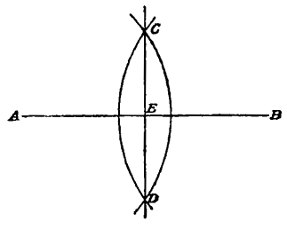
Fig. 2.
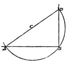
Fig. 1.
Fig. 2.
To erect a Perpendicular to a given Straight Line.
—Let it be required to erect a line perpendicular to the point B (Fig. 2) in the line A B. From any point C above the line, with radius B C, describe an arc as A B D; join A C and produce the line until it cuts the arc in D, and join D B; then will D B be perpendicular to A B.
Fig. 3.
To divide a Line into any number of equal parts.
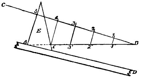
—Let it be required to divide the line A B (Fig. 3) into five equal parts. From B, at any angle, draw B C, and on the line B C lay off five equal parts, 1, 2, 3, 4, 5; then take a set square E, and make one of the sides containing the right angle coincide with the points A and 5, and to the other side apply a straight-edge D; then by passing the set square along the edge of the straight-edge and drawing lines from the points 4, 3, 2, 1, through the line A B, we shall have the line A B divided into five equal parts through the points 1′, 2′, 3′, 4′.
To draw a Line making, with another line, a given Angle.
—Let it be required to draw a line making with the line A B (Fig. 4) an angle of 35°. From a scale of chords, which will be found on most scales supplied with a set of instruments, take off 60°; from the point A, with this distance for radius, describe an arc C D; lay off on this arc the distance of 35° taken from the same scale of chords; from A draw a line through this point. Then will the line A E make with the line A B an angle of 35°. The same result may be more readily arrived at by means of a protractor. If the centre point of the protractor be placed on the point A and its base made to coincide with the line A B, we can from its circumference prick off the distance of 35°, and a line drawn from A through the point thus found will make, with the line A B, the required angle of 35°.
Fig. 4.
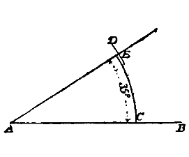
Fig. 5.
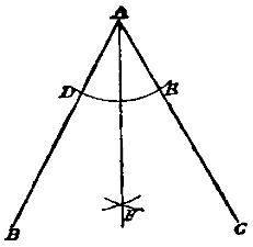
Fig. 4.
Fig. 5.
To bisect an Angle.
—Let B A C (Fig. 5) be the angle which it is required to bisect. From A, with any radius, describe an arc cutting the lines A B and A C in D and E; from D and E, with the same or any other radius, describe arcs cutting each other in F, and from A draw a line through F; this line will bisect the angle as required.
Fig. 6.
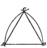
Fig. 7.
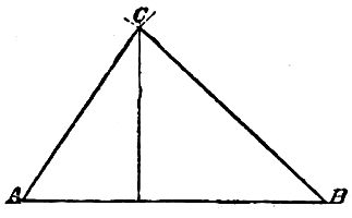
Fig. 6.
Fig. 7.
To construct an Equilateral Triangle on a given base.
—Let A B (Fig. 6) be the given base. From A and B, with radius A B, describe arcs cutting each other in C; join A C and C B, which will complete the required triangle.
To construct a Triangle, the lengths of the Sides being given.
—Let it be required to construct a triangle whose sides shall be equal respectively to 6, 5, and 4. Lay down the base A B (Fig. 7), making it equal to 6 divisions of the scale; from A with radius equal to 4 divisions, and from B with radius of 5 divisions of the scale describe arcs cutting each other in C; join A C and C B, which will complete the required triangle.
Fig. 8.
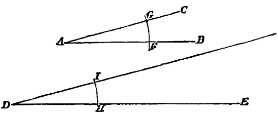
To construct an Angle equal to a given angle.
—It is required to draw a line making with the line D E (Fig. 8) an angle equal to that contained by the lines B A C. From A, with any radius, draw an arc F G, and from D, with the same radius, draw the arc H I, and make H I equal F G; then a line drawn from D through I will make, with the line D E, an angle equal to the angle B A C.
Fig. 9.
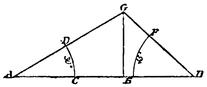
To construct a Triangle, the length of the base and the angles at the base being given.
—It is required to construct a triangle whose base shall equal 1 inch, and the angles at the base be 30° and 45° respectively. Having made the base A B (Fig. 9) of the required length, make the angles at A and B of the required magnitude in the manner already described (see Fig. 4), and the continuation of these lines meeting in the point G will complete the construction of the required triangle.
Fig. 10.
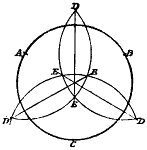
To describe a Circle which shall pass through three given points.
—Let A B C (Fig. 10) be the points through which it is required to draw the circle. From each of these points, with any radius, describe arcs cutting each other in D and E; join the points D and E, and the point where these lines intersect will be the centre from which to describe the circle which will pass through the points A B C as required.
Fig. 11.
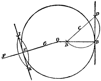
To draw a Tangent to a circle.
—I. Let B (Fig. 11) be the point from which it is required to draw the tangent. Draw the radius O B, and at B erect a perpendicular (see Fig. 2); then will the line B D be a tangent to the circle. II. It is required to draw a tangent from the point E in the same circle. Draw the radius O E extending beyond the circumference to F, and make E G equal to E F. From F and G, with any radius, describe arcs cutting each other in H and I; then a line drawn through these points will be a tangent to the circumference at E.
Fig. 12.
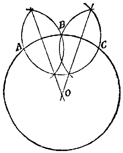
To find the Centre of a circle.
—From any point in the circumference, as B, (Fig. 12), describe an arc cutting the circumference in A and C, and from A and C, with the same radius, describe arcs cutting the first arc in two points; through the points of intersection draw lines to the interior of the circle, and the point O where these lines intersect will be the centre of the circle.
Fig. 13.
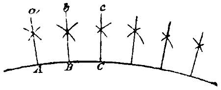
To draw lines which shall be Radii of a circle, the centre being inaccessible.
—Having laid off on the circumference of the arc, the distances apart of the radii, as A, B, C, &c. (Fig. 13), from each of these points, with radius greater than a division, describe arcs cutting each other as at a, b, c, &c., join A a, B b, C c, &c., and the lines so drawn will be radii of the circle as required.
Fig. 14.
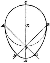
To construct an Oval, the width being given.
—Draw the line A B (Fig. 14) equal to the width, and bisect A B by C D (see Fig. 1). From the point of intersection E, with radius E A or E B, describe the circle A C B F, and from A and B through F, draw the lines A G and B H. From A, with radius A B, describe the arc B G, and from B, with the same radius, describe the arc A H; also from F, with radius F G or F H, describe the arc G D H, which will complete the required oval.
Fig. 15.
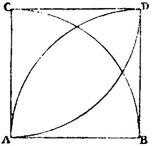
To construct a Square on a given line.
—Let A B (Fig. 15) be the given line. At A erect a perpendicular (see Fig. 2), and from A, with radius A B, describe an arc cutting the perpendicular in C; also from B and C, with the same radius, describe arcs cutting each other in D; join C D and B D, which will complete the required square.
Fig. 16.
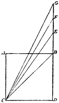
To construct a square that shall be a Multiple of any given square.
—Let A B C D (Fig. 16) be the given square, and let it be required to construct a square that shall contain 2, 3, 4, &c., times its surface. Draw the diagonal B C, then the square described on B C will be double the square A B C D. Lay off D E, equal to B C, and draw C E; then the square described on C E will be three times the square A B C D. In the same manner lay off D F, equal to C E, and the square described on C F will be four times the square A B C D; and so for any multiple of the square A B C D.
Fig. 17.
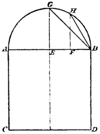
To construct a square that shall be equal to 1⁄2, 1⁄4, &c., of any given square.
—Let A B C D (Fig. 17) be the given square. On A B, as a diameter, describe the semicircle A G B, and erect at the centre E the perpendicular E G. Draw G B, which will be the side of a square equal to one-half of A B C D. Lay off B F, equal to one-fourth of A B, and erect the perpendicular F H; then the square described upon H B will be equal to one-fourth of A B C D. In the same manner a square may be constructed equal to any part of A B C D.
Fig. 18.
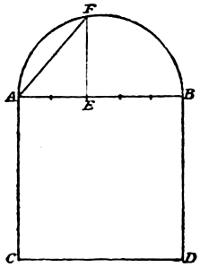
To construct a square that shall be in any Proportion to a given square.
—Let A B C D (Fig. 18) be the given square. It is required to construct a square which shall be to A B C D as 2 is to 5. Upon the side A B as a diameter describe the semicircle A F B, and divide the line A B into five equal parts. At the second point of division erect the perpendicular E F and join A F; the square described upon A F will be to the given square A B C D as 2 is to 5.
Fig. 19.
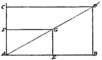
To construct, upon a given base, a Rectangle, which shall be similar to a given rectangle.
—Let A E F G (Fig. 19) be the given rectangle. It is required to construct upon the base A B, one that shall be similar to A E F G. Produce A E and lay off the given base from A to B; draw the diagonal A G and produce it indefinitely. Erect a perpendicular to A B at B, and from the point D where it intersects the diagonal produced, draw D C perpendicular to A F produced. Then A B C D will be similar to A E F G. All rectangles having their diagonals in the same line are similar.
Fig. 20.
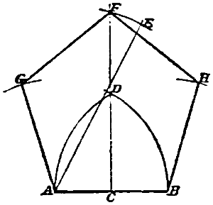
To describe a regular Pentagon on a given line.
—Let A B (Fig. 20) be the given line. Bisect A B at C, draw C F perpendicular to A B, and make C D equal to A B. Draw A D and produce it indefinitely; make D E equal to half A B. From A as a centre, with A E as a radius, describe an arc cutting the perpendicular C D in F; and from A F and B as centres, with radius A B, describe arcs cutting each other in G and H; join A G, B H, F G and F H; then A G F H B will be the pentagon required.
Fig. 21.
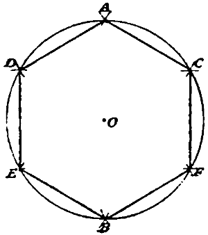
To describe a regular Hexagon.
—With a radius equal to the length of one side of the required hexagon, describe a circle (Fig. 21), and set off the same radius round the circumference of the circle, which will be thus divided into six equal parts. Join the points thus found, and the required hexagon will be completed as A B C D E F.
Fig. 22.
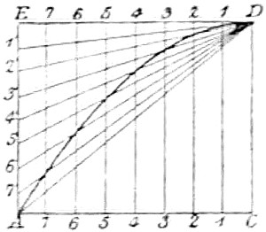
To draw a Parabola, the base and height being given.
—Let C A (Fig. 22) equal half the base, and C D the height. From the point D draw D E parallel and equal to A C, and from the point A draw A E parallel and equal to C D. Divide D E and A E similarly, making the end E of A E correspond to the end D of E D. Through 1, 2, &c., in DE draw 1, 1; 2, 2, &c., parallel to D C. Join D to the several points 1′, 2′, &c., in A E. The parabola will pass through the points of intersections of these lines with the verticals drawn from D E to C A.
Fig. 23.
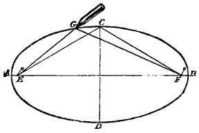
Fig. 24.
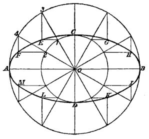
Fig. 25 a.
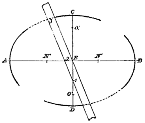
Fig. 25 b.
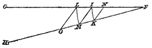
Fig. 23.
Fig. 24.
Fig. 25 a.
Fig. 25 b.
To draw an Ellipse.
—I. By means of a piece of string and pins. Place the diameters A B and C D (Fig. 23) at right angles to each other, and set off from C half the major axis at E and F; then will E and F be the two foci in the ellipse. Fix a pin at E and another at F; take an endless string equal in length to the three sides of the triangle E F C and pass it round the pins, stretch the string with a pencil G, which will then describe the required ellipse. II. From the centre O (Fig. 24) describe a circle of the diameter of the minor axis of the required ellipse. From the same centre, describe another circle with a diameter equal to its major axis. Divide the inner circle into any number of equal parts as 1, 2, &c., and through these points draw radii cutting the outer circle in 4, 3, &c. From 1, 2, &c., draw horizontals, and from 3, 4, &c., draw perpendiculars cutting each other in E F, &c.; the curve traced from C through the points C E F A, &c., will complete the curve of the required ellipse. III. Let A B (Fig. 25 a) be the major and C D the minor axis of the required ellipse. On any convenient part of the paper draw two lines F G, F H (Fig. 25 b) at any angle with each other. From F with the distance E C or E D, the semi-axis minor, describe an arc cutting the lines F G, F H, in I and K; and from F with the distance E A or E B, the semi-axis major, describe the arc L M. Join I M, and from L and K draw lines parallel to I M, cutting F G, F H, in N and O. From A and B (Fig. 25 a) set off the distance F N (Fig. 25 b) in points N′, and from these points as centres, with F N as radius, describe an arc of about 15° on each side of the major axis. From C and D (Fig. 25 a) set off on the minor axial line the distance FO (Fig. 25 b) in points O′, and from these points as centres, with radius FO, describe arcs of about 15° on each side of the axis C D. To obtain any number of intermediate points take a slip of paper (Fig. 25 a) and mark upon one edge, with a sharp-pointed pencil, 1, 3, equal to the semi-axis major, and 2, 3, equal to the semi-axis minor. If the slip of paper be now applied to the figure and moved over it in such a manner that the point 2 is always in contact with the major axis, and the point 1 in contact with the minor axis, the outer point 3 will describe a perfect ellipse, any number of points in which can be marked off as the “trammel” is moved into successive positions.
For this last method, which in practice is by far the best, we are indebted to Binns’ ‘Orthographic Projection.’
Fig. 26.
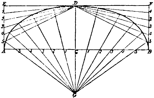
To construct a Semi-Elliptical Arch.
—The span A B (Fig. 26) and rise C D being given, divide C A and C B into any number of equal parts. Through the point D, draw E F parallel to A B, and from the points A and B erect the perpendiculars A E and B F. Divide A E and B F similarly to C A and C B. Produce C D and make C G equal C D. From D draw lines to the points 1, 2, 3, &c., in the lines A E and B F; also from G draw lines through the points 1, 2, 3, &c., in the line A B, and produce these lines until they cut those drawn from D to the corresponding numbers in A E and B F. Through the points thus obtained draw the curve of the ellipse.
Fig. 27.
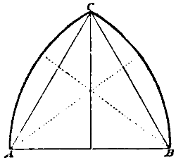
To draw the Gothic Equilateral Arch.
—From the points A and B (Fig. 27), with radius A B equal to the span, describe the arcs B C and A C. By joining C to A and B we obtain an equilateral triangle from which this arch derives its name.
Fig. 28.
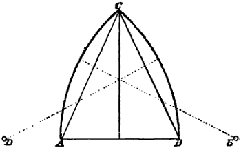
To draw the Gothic Lancet Arch.
—In this arch, the centres E and D (Fig. 28) from which the arcs are struck, are situate outside of and in a line with the points of springing A and B; thus it is constructed on an acute-angled triangle, as will be seen by joining C to A and B.
Fig. 29.
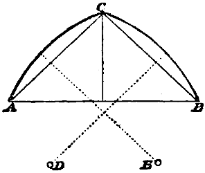
To draw the Gothic Obtuse Arch.
—This arch, called sometimes the Drop-Arch, is constructed on an obtuse-angled triangle; the centres E and D (Fig. 29) being situate below and within the points of springing A and B.
Fig. 30.
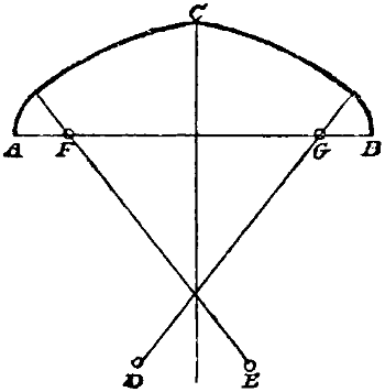
To draw the Gothic Tudor Arch.
—On the line of springing A B (Fig. 30), take any two points as F and G, so that A F is equal to G B. Draw F E and G D cutting each other on the bisecting line through C; from F and G, with radius F A or G B, describe the short arcs, and from E and D, with radius E C or D C, describe the arcs meeting in C.
Fig. 31.
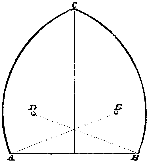
To draw the Moorish Horse-Shoe Arch.
—The centres E and D (Fig. 31) from which the arcs forming this arch are struck, are situate above and within the points of springing A and B. One of the most graceful forms of this arch is obtained when the height of the points E and D above the line of springing and their distance from the bisecting line through C are equal to one-third of the span A B.
Fig. 32.
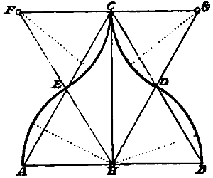
To draw the Gothic Ogee Arch.
—The most pleasing form of this arch is that constructed on an equilateral triangle, in the following manner. Having drawn the equilateral triangle A B C (Fig. 32), draw F G parallel to A B. Bisect the sides A C and C B and produce the bisecting lines to F G and H, which will complete the triangle F G H similar and equal to the triangle A B C. From H, with radius H A or H B, describe the arcs A E and B D, and from F and G, with the same radius, describe the arcs E C and C D.
Fig. 33.
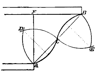
Fig. 34.
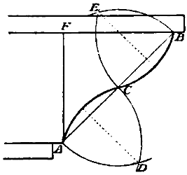
Fig. 33.
Fig. 34.
To draw the Roman Cyma Recta and Cyma Reversa.
—Join A B (Fig. 33) and bisect A B in C. From the points C and B, with the distance B C, describe arcs cutting each other in E; and from A and C, with the same radius, describe arcs cutting each other in D; from D, with the same radius, describe the arc A C, and from E describe the arc C B. The projection of the upper end of the curve over the under, as F B, is generally equal to the height, A F, of the moulding. The same description applies to the Cyma Reversa (Fig. 34) letter for letter.
Fig. 35.
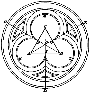
To draw the Gothic Trefoil.
—Having drawn the equilateral triangle A B C (Fig. 35), bisect the angles and produce the bisecting lines D E F which will bisect the sides of the triangle in G H I. From A B and C as centres, with radius A H or A I, equal to half the side of the triangle, describe the arcs K L M, and those concentric with them, and from the centre O of the triangle describe the outer circles and concentric arcs, which will complete the figure.
Fig. 36.
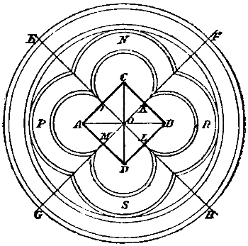
To draw the Gothic Quatrefoil.
—Draw the square A B C D (Fig. 36); bisect the sides of the square at I K L M and produce the bisecting lines to E F G H. From the angles A B C D of the square as centres, with radius A I or A M equal to half the side of the square, describe the arcs P N R S, and draw the outer concentric arcs. The circles, completing the figure, are drawn from the centre O of the square.
Fig. 37.
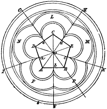
To construct the Gothic Cinquefoil.
—Having drawn the regular pentagon A B C D E (Fig. 37), bisect the angles and produce the bisecting lines to F G H I K, which will cut the sides of the pentagon in a, b, c, d, e. From A B C D and E as centres, with radius A a or A b, equal to one-half of the side of the pentagon, describe the arcs L M N P R, and draw the outer concentric arcs and those concentric with them. The circles are drawn from the centre O of the pentagon, as in the preceding example.
Section III.—Lines, Dots, and their Combinations.
All kinds of drawings are made up of lines and dots; these are the constituent parts, the materials which the draughtsman has to employ. It is therefore essential that he should make himself acquainted with their various forms and uses, and familiar with those means of producing them which experience has shown to be the best, before commencing the study of the principles by which the representation of an object is delineated. And moreover, it is desirable that he should acquire a familiarity with the operations required in the delineation of isolated objects, previously to making any attempt to place them in combination for the purpose of producing a complete drawing. The student will, therefore, do well to study carefully and to practise diligently the forms and examples given in this Section.
Straight and Curved Lines.
—All straight lines, however short, should be ruled, whether they be drawn with the pencil or the pen. Pencil lines, which are intended to serve merely as guides to the pen, should be drawn lightly, as otherwise it will be difficult to rub them out without injuring the ink. They should also be drawn a little beyond the point at which the line is required to terminate, because the intersection of the lines at that point makes it more distinctly visible, and there is, consequently, less danger of passing beyond that point or of stopping short of it when inking in. It is very important not to stop short of the required length when ruling a straight line with a pen, for it is extremely difficult to lengthen the line subsequently without leaving the join visible. An accurate line cannot be drawn unless the point of the pencil or the pen be kept close up to the rule, and to do this the top should be inclined a little outward. Before inking in a line that has been drawn in pencil, the indiarubber should be passed lightly over it, to remove the particles of lead adhering to the paper, for if these particles are allowed to remain, they get between the nibs of the pen and prevent the ink from flowing freely. The chief difficulties in ruling a straight line with the pen are, to keep it of a regular thickness throughout, and, when numerous parallel lines have to be drawn, to keep them at equal distances apart. To draw an even line, a first requisite is that the pen be in good condition. Frequently it will be found when drawing fine lines that the pen ceases to mark before the end of the line is reached, and as we have already said, it is very difficult to join a line without leaving visible traces of the operation. To remedy this defect, the pen must be reset as described in Section I. If a very hard pencil has been used, or if the pencil has been pressed heavily upon the paper, the pencil line will lie in a groove in the paper, and as the nib of the pen will not touch the bottom of this groove, the line drawn will be ragged. Another cause of unevenness is unduly pressing the pen against the rule; this pressure closes the nibs, and besides producing an irregularity in the thickness of the line, is very apt to cause a blot by forcing out the ink, which adheres to the rule when brought into contact with it. To prevent this, care should be taken to press the pen very lightly against the edge of the rule. A pen is manufactured by Stanley, of Holborn, London, which has the back nib much stiffer than the other, so that all danger of defect from this cause is removed by the construction of the instrument. To ensure a good line, the pen should rest lightly upon the paper, and the handle of the pen should make the same angle with the paper from the beginning to the end of the line. A considerable amount of practice is required to accomplish this, and to acquire the habit, the same attention should be given to the pencil as to the pen. The ability to draw a number of parallel lines at equal distances apart without measuring requires considerable training of the eye, and this training can be obtained from practice alone. This ability must be acquired before anything further is attempted, and the student who spends a good deal of time in its acquisition may have the satisfaction of knowing that while he is going through this somewhat monotonous practice, besides exercising himself in drawing accurate lines, he is acquiring a correctness of eye and a power of hand that will be of incalculable service to him later.
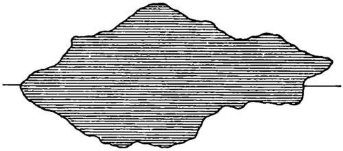
The straight line, besides being used for the outlines of regular objects, is employed conventionally for various purposes. When it is required to show an object in section, the part in section is covered with straight and parallel lines drawn at an angle of 45° and at equal distances apart, as in Fig. 38. To represent standing water, as ponds and lakes, horizontal straight lines are drawn parallel to each other and at equal distances apart over the surface, as shown in Fig. 39.
Fig. 38.
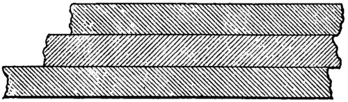
Fig. 39.
Curved lines, when arcs of circles, are drawn by the compasses. Other curves are drawn by hand through points previously found. To draw the curve correctly through these points, unless they be very numerous, a knowledge of the nature of the curve is necessary, which the draughtsman should in all cases endeavour to obtain. When the curved line is long, it is usually inked in with the drawing pen, with the aid of an instrument called the French curve, or cardboard moulds cut for the purpose; but for short lines an ordinary fine-pointed steel-pen point, or better, a good quill is used. In general, all lines drawn by hand should be drawn towards the body, as a better command of the pen can be obtained in that direction than in any other. In inking in curves by this means, the draughtsman should proceed continuously along the pencil-drawn line by partly repeated touches with the pen point, so held that the divided points of the pen may follow partly in the same track. Each touch should be made about one-thirtieth of an inch in length, and it should begin and end fine. Each succeeding touch must begin half its length back, so that the line is advanced by one-sixtieth of an inch. In map drawing all irregular lines are drawn in this way. Tracing maps will afford the student excellent practice in this mode of using the pen.
Fig. 40.
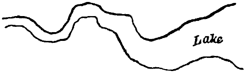
Lines of uneven thickness.
—Though generally a line is required to be of even thickness throughout, cases sometimes occur in which a variation in the thickness may be made to express some feature or quality of the landscape. The usual application of this kind of line is to mark the outline of rivers, lakes, and ponds, as shown in Fig. 40. The drawing of such a line presents no difficulty; the increased thickness is produced by going over those parts of the line again with the pen. Care must, however, be taken not to make a sudden increase in the breadth of the line, but to begin and end imperceptibly.
Fig. 41.
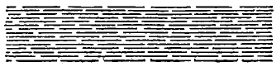
Fig. 42.
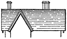
Fig. 41.
Fig. 42.
Fig. 43.
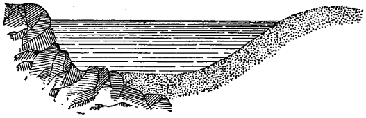
The Broken Line.
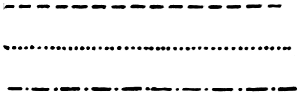
—The broken line, shown in Fig. 41, is of frequent occurrence in all kinds of drawings. In architectural and engineering drawings it is usually employed in roofs, as in Fig. 42, and for water in sections, as in Fig. 43. It is also used in combination with other lines for various purposes. In drawing a succession of broken lines, care must be taken not to allow the break in one line to be immediately over that in another. The effect may be varied considerably by increasing or diminishing the extent of the break. As in section lining, the lines should be at regular intervals apart, and be all of the same degree of fineness. Broken lines are sometimes used upon the face of stone buildings, instead of marking in the joints and etching or colouring. In such a case the breaks are long, and the lines widely spaced.
Fig. 44.
The Dotted Line.
—Of still more frequent occurrence is the dotted line. There are two kinds of dotted lines, distinguished by the shape of the dot, and known as the long and the round dotted line. These are shown in Fig. 44, as well as a combination of the two.
The round dotted line is of very general application. In architectural and mechanical drawings, it is used to distinguish hidden parts, and to mark the path of a moving piece in a machine. In plans, it is used to show the position of proposed works, to denote the walks through pleasure grounds and gardens, to indicate lines chained over in surveying, and frequently for other purposes, at the pleasure of the draughtsman. The long dotted line is employed to mark the boundaries of a township, the navigable channel of a river or creek, and in large-scale maps to show farm and bridle roads, footpaths, and the divisions of land among different tenants. The combination of the long and round dotted lines is used for the boundaries of a parish. Another combination of two round and one long dots, or sometimes of three round and one long, is used to denote proposed railways, canals, roads, and other similar works.
To draw a good dotted line requires some care. The difficulty lies in keeping the dots at equal distances apart, and in making them equal in size; and unless both these conditions are fulfilled, the line will not present a pleasing appearance. To obviate this difficulty, an instrument is sold by mathematical instrument makers, called the dotting or wheel pen. But it requires very great care in using, as otherwise it frequently happens that the ink escapes from it and spoils the drawing. For this reason, its use has been generally abandoned by draughtsmen. But if the instrument were better constructed and carefully handled, it might be made to do good service.
Fig. 45.
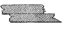
Fig. 46.
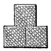
Fig. 45.
Fig. 46.
Fig. 47.
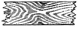
Fig. 48.
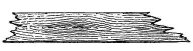
Fig. 49.
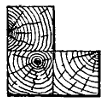
Fig. 48.
Fig. 49.
Combinations of Straight, Broken, and Dotted Lines.
—Combinations of the foregoing lines are used for various purposes. Some draughtsmen employ alternate, full, and dotted lines, to denote wood in section, as in Figs. 45 and 46; when wood is used in combination with iron or other metal, this is a very good way of distinguishing it. Wood-graining, though not made up of straight, broken, or dotted lines, yet partakes somewhat of the nature of all three kinds, and may therefore be introduced here. Oak-graining is shown in Fig. 47, and fir-graining in Fig. 48. The former is executed with the drawing pen, and requires some care and practice; the latter is most readily done with a common pen or a crow-quill. End wood is grained as shown in Fig. 49. The spring bows are very suitable for drawing in the circles, as a certain degree of turn to the nut will open the ink leg to the required distance after drawing each circle. A few broken wavy lines, called shakes, radiating from the centre, produce a good effect. When several pieces of end wood come together, the centres in each should not be in the same relative position.
Fig. 50.
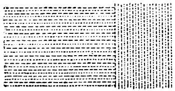
Cultivated land is represented by alternate broken and dotted lines, suggesting furrows, as shown in Fig. 50. For the sake of variety, these lines are put in in sets, and in different directions, one set being usually parallel to one side of the enclosure. The lines are first ruled in continuously with the pencil, and the broken and dotted lines afterwards drawn in over them by hand. The portions of the broken lines must in this case be short, and the breaks still shorter. The dots must be fine and close together; they are made by touching the paper with the point of the pen, and immediately lifting it off without dragging it over the paper. All round dots must be made in this way.
The Wavy Line.
—The wavy line is very important in topographical drawings, as it is employed to represent running water, and frequently large bodies of standing water to which motion is communicated by the wind, as lakes and the sea. These rippled lines are intended to represent the ripples in the water, a purpose which they fulfil in a very pleasing manner. They must, however, be well executed, or the pleasing effect will not be produced. The operation of drawing these lines is usually regarded by the draughtsman as a tedious and an uninteresting one. But such ought not to be the case, for there is ample scope in it for the exercise of the taste and the judgment, and in proportion to the taste displayed and the judgment exercised, will be the effect of the work when executed.
Fig. 51.
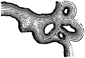
Fig. 51 shows the manner of employing these lines. In representing water by this means, the lines should be drawn from the shores towards the middle of the stream or lake, and never from the middle outwards, for if the latter mode of proceeding be adopted, the proper graduation of the spaces between the lines becomes impossible. The shore line, or outline of the water, should be a moderately thick line, and of uniform thickness throughout. The first shading line may be of nearly the same thickness as the shore line, and it must be drawn as near to it as possible. Also this shade line, as well as all subsequent ones, must follow exactly all the windings of the shore line; this is essential to a correct expression. To effect this with accuracy, care should be taken to make the space between the shore and the shade line a fine white line. The second shade line must be drawn a little finer than the first, and at a slightly increased distance from it. This gradual diminution of the thickness of the lines, and increase of the spaces, must be continued to the middle of the current. The last line in the middle of a piece of water must always return to itself. When the shading lines meet the margin of the drawing, they should terminate in it, that is, they should be drawn out to the margin as though they had been continued beyond and cut off.
These lines require to be drawn clean, and to do this the hand must be kept steady. This steadiness may be obtained by taking a very short hold of the pen, and resting the middle finger upon the paper. The lines, as we have already said, should be drawn towards the body, the drawing being turned about as required to facilitate this, and the last line drawn must be always kept on the left of the one being drawn. By this means the last line and the point of the pen are kept constantly in sight. It is also important that the lines should be completed successively, rather than that several should be carried on at once, because if the latter mode of working be adopted, the eye is apt to become confused by the different intervals, and an uneven distribution of the lines is the result. A principle to be attended to is that every line shall return to itself, spirals being altogether inadmissible. The distance of the lines apart and their thickness are expressive of the character of the object; thus, in a small pond, for example, they will be fine and close together; in a large pond or a lake they will be thicker and more widely spaced; and in the open sea they will be made to present a bold appearance by increasing still more their thickness and the distance between them.
Fig. 52.
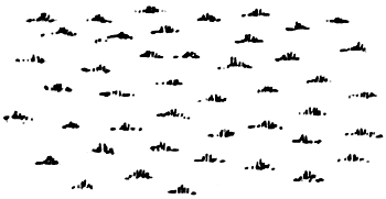
Grass-land.
—Various combinations of lines and dots are used, conventionally, to represent certain natural features of common occurrence. As far as convenient execution will allow, these signs are made to resemble the objects denoted. Thus the sign for grass-land consists of groups of short lines, arranged like tufts of herbage, as shown in Fig. 52. Each tuft is composed of five or seven lines converging towards a point situate below the base, the middle line being the longest, and the outside ones mere dots. In drawing these groups, the base must be kept quite straight, and parallel to the base of the drawing whatever the shape of the enclosure may be. Beginners usually experience considerable difficulty in keeping the base straight, the tendency being to make it curved. Great care is needed to distribute the groups evenly over the paper, and to avoid the appearance of being in rows, for the latter arrangement is destructive of that natural aspect which this sign otherwise possesses.
Fig. 53.
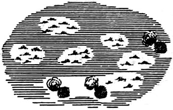
Swamps and Marshy Ground.
—As the surface of marshy ground consists of water and grass, a combination of the signs for these objects is employed to represent it. An illustration of this is given in Fig. 53. The lines representing the water should always be ruled parallel to the base of the drawing, and they should be grouped in an irregular manner so as to leave small islands interspersed throughout the locality. These islands should be covered with grass, and to show them out more distinctly, there should be nothing but water immediately around them. The division between the land and the water should be sketched in lightly before proceeding to rule in the lines. Sometimes dotted lines are used for the water, but full lines are to be preferred. The addition of a tree here and there improves the appearance of a drawing. A distinction is frequently made between a swamp and a marsh by watering the former more extensively than the latter. In drawing in marsh land, care should be taken to make the fineness of the lines in accordance with the scale of the map, as otherwise an offensive appearance will be produced. This caution applies equally to all signs.
Fig. 54.
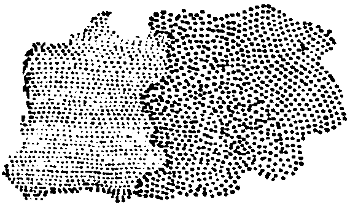
Sand and Gravel.
—Sand and gravel are represented by dots, the dots being made larger for the latter than for the former, as shown in Fig. 54. Simple as the operation of filling in these dots is, it is one that requires some degree of care. Beginners are apt to mar the appearance of their drawings by inattention in this respect. The dots should be made in the manner already described when speaking of the dotted line, that is, the point of the pen should be brought slowly down upon the paper, and lifted without dragging it; and no dot should be made without a deliberate intention respecting its position. All arrangement in rows must be carefully avoided. In sand-hills, the slopes should be made darker than the level parts by placing the dots closer together. Mud in tidal rivers may be represented by very fine dots placed close together.
Fig. 55.
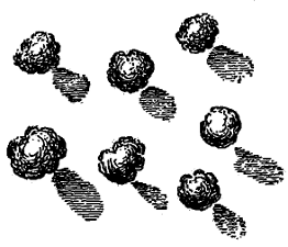
Fig. 56.
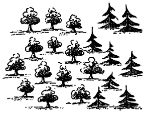
Fig. 55.
Fig. 56.
Woodland.
—Trees are generally shown in plan (as in Fig. 55). The outline is circular in character, and, to have a good effect, it should be made up of simple curves firmly drawn; small indentations should be avoided as bad. A few touches of the pen are given on the interior and towards the shadow. The latter is cast by parallel rays of light inclined 45° to the horizon, and is detached from the outline of the tree. When the scale is large, the shadow will be elliptical in form, but in small scales it will become a simple circle. In representing woodland, the trees and masses of trees should be disposed in every possible variety of position, care being taken, however, to avoid all regular figures and arrangements in lines. In parks and gardens, where the arrangement of the trees is artificial, it is usual to represent a grove in a rectangular form. Orchards are shown by placing single trees with their shadows at the points of intersection of two sets of equidistant parallel lines drawn at right angles to each other. These lines are drawn in pencil and afterwards erased. Some draughtsmen prefer to draw trees in elevation, as shown in Fig. 56. This method allows the various kinds of trees to be distinguished on the plan, and gives scope to artistic skill.
Fig. 57.
Uncultivated Land.
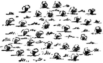
—Uncultivated land, other than woodland, is represented by drawing bushes in plan, similar to trees, but of smaller dimensions, and mixing tufts of grass with them, as shown in Fig. 57.
Fig. 58.
Contour Lines.
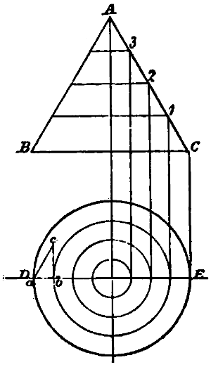
—Suppose a cone A B C (Fig. 58) cut at regular vertical intervals apart by a series of horizontal planes 1, 2, 3. The intersections of these planes with the surface of the cone will give lines upon that surface; and it is obvious that the cone may be represented in plan by the projection of these lines, as shown in the figure. To obtain this projection, draw the horizontal line D E, and from the apex of the cone and from the intersections of the cutting planes let fall vertical lines. From the point where the line from the apex meets the line D E as a centre, with radii equal to the distances from this point to those where the lines from the sections meet D E, describe circles. These circles will be the horizontal projections of the lines on the surface of the cone produced by the cutting planes; and these lines are called contour lines. Also it is obvious that, from the plan of the cone so obtained, we may as readily project the elevation, provided we know the vertical distance apart of the sections denoted by the contour lines. To obtain the elevation, we have only to draw horizontal lines at the given distance apart, and from the points in D E erect perpendiculars to meet them. Lines drawn through the points of intersection will give the elevation of the cone. To find the inclination of the surface of the cone, upon a b, a portion of the normal D E, as a base, erect a perpendicular b c, equal in height to the distance of the sections apart, and join a c. The hypothenuse a c then represents that portion of the surface of the cone which is included between the two contour lines, and of which the angle of inclination is b a c. The space between two contour lines is called a horizontal zone.
The cone being a regular figure, its contour lines are circles. For irregular figures, the contour lines will be irregular curves. The regular inclination of the surface of the cone causes the projections of the contour lines to be at equal horizontal distances apart. But when the inclination varies, the horizontal distance between the contour lines also varies, the distance decreasing as the inclination increases. Thus the method of representing objects in plan by contour lines, not only gives the correct form of the object, but shows the relative inclination of every portion of its surface. This may be clearly seen in Figs. 59 and 60, the former of which is a representation in plan by contour lines of an irregularly shaped object, and the latter an elevation of the same object projected from the plan.
Fig. 59.
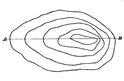
Fig. 60.
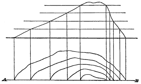
The system of representation by contour lines is generally adopted by topographers to distinguish and define the variation of the surface of the ground in regard to hill, valley, and plain. By intersecting a mountain, for example, by a sufficient number of horizontal planes, its correct form may be delineated, and the declivity of its surface accurately shown. The relative declivity of any portion of its surface is indicated by the difference in the horizontal distance of the curves apart; and by constructing a triangle upon a normal to the upper curve in the manner already described for the cone, the absolute slope at any point between any two curves may be readily determined. The ground is supposed to slope uniformly from one curve or contour line to the next. Such, however, is rarely the case; but provided the curves are taken at frequent intervals, the error is of no practical importance. Hollows are represented in the same way; and whether the representation is that of a hill or a hollow, is known from the other parts of the map. Thus, if Fig. 59 represent a hill, the vertical projection will be as shown in Fig. 60; but if it denote a hollow, the outer curve must be projected highest, and the vertical section will be Fig. 60 inverted. In practice the contour lines are numbered, the number of any contour indicating its height above a plane of reference called a datum plane. The vertical distance of the contour lines apart varies with the character of the ground and the object of the survey; but it is seldom less than 25 feet. The lines are obtained by the surveyor by fixing a number of points on the same level by means of instruments.
Section IV.—Colours.
The preceding Section treats exclusively of representation by lines and dots, or that mode of delineating objects and natural features known as line or pen drawing. There is, however, another mode of representation by means of colours that is fast coming into general use. This latter mode is far more expressive than the former, and, besides affording a wider scope for artistic effect, shows with greater distinctness and precision the character of the object represented. For these reasons it is almost always adopted for plans of estates and geological sections, and also very frequently for other kinds of topographical as well as for engineering and mechanical drawings. The colours used for this purpose are not applied in the way the artist applies them; but they are laid on in thin washes to produce a faint tint rather than a body of colour. The process is called tinting or flat-washing, and though it cannot be described as a work of art, considerable practice and skill are requisite to execute it properly.
Flat-tints.
—A drawing to be coloured must be previously stretched and gummed to the board, in the manner described in Section I. Unless the paper be prepared in this way, it will remain blistered after being wetted by the laying on of the tints. The lines of the drawing must be very fine, and the ink, though black, should not be thick. Great care should be exercised in drawing in the outlines, that there be always a piece of clean paper between the hand and the drawing, for the least degree of greasiness will prevent the colours from working freely. Should the surface of the paper, however, from inattention to this matter, or from accident, become slightly greasy, the defect may be partially remedied by adding a little prepared ox-gall to the water with which the colours are mixed. When all the outlines have been drawn in and the pencil lines erased, the drawing is prepared for the colouring by being washed. The washing is effected by passing a soft sponge well saturated with clean water gently and rapidly over the surface. The purpose of this washing is twofold; first, to remove those portions of the ink which a wet brush would detach from the paper in laying on the colours, and which, by becoming mixed with the tint, would injure its purity; and second, to damp the surface of the paper in order to prevent the colour from drying too rapidly. The latter is an important matter, for if the tint which is being applied dries quickly, it is impossible to unite the edges properly, and the tint, especially if the surface be large, will have a cloudy and blotchy appearance. As the operation of washing renders the paper too wet to immediately receive the colour, it must be allowed to remain in a perfectly horizontal position for a short time to dry, and during this time any tendency to dry unequally must be corrected by means of blotting-paper. While the paper is drying, the tints may be prepared.
To ensure satisfactory results, care must be taken in the preparation and preservation of the tints. They should never be made by artificial light, and a sufficient quantity should be made at first to cover all the portions required, as it is very difficult to match a tint exactly. When a drawing is several days in hand, it is best to prepare a fresh tint for every coat, for the colours will change in the course of a day or two, even if protected from the light. A few drops of water should be added now and then, to make up for the loss by evaporation, especially in warm weather. Tints left to dry upon the palette should never be wet up again for use, but they should be washed clean out and a fresh tint made; if this precaution be not attended to, the colour will not be pure. When a tint is to be mixed, the end of the cake of colour should be moistened and allowed to soften for a minute or two, as this will cause it to rub smooth and free from fragments. The palette should then be moistened and the end of the cake rubbed gently and evenly upon it till a sufficient quantity of colour has been obtained, which may be added to the requisite quantity of water by means of a brush. A precaution necessary to be observed is never to rub one colour down upon another, as it will probably be laid aside to dry with the other colour on it. The brush used should be as large as the nature of the work will allow, and it should be of the best sable hair; the quality is judged by the length of the hair, the longest and stiffest being the best. Draughtsmen frequently do all their work with a couple of sable brushes attached to one holder, one being for colour and the other for water; in this case the brushes should be of different colours to prevent mistakes.
The art of laying on a flat-tint consists in allowing the coloured water to flow equally over the paper, which thus becomes uniformly tinged. To facilitate this, the surface of the drawing should be inclined towards the draughtsman at an angle of about five degrees during the process of laying on the colour. Having taken as much colour on the brush as it will safely carry without dropping, the operation of applying it should be begun in the upper left-hand corner, the brush being carried along towards the right, so as to make the colour lie neatly along the upper outline. The brush should then be struck unhesitatingly from right to left and from left to right alternately, so as to bring the colour down in horizontal bands or stripes, taking care not to pass the brush a second time over the same surface during the same wash, and to control it neatly within the proper limits. If the surface of the paper be in this way kept well wetted with the colour, or if, in other words, a flow of colour be kept in motion with the point of the brush, the tint can be carried on with perfect continuity. It is important to keep as nearly as possible the same quantity of colour in the brush until the lower outline is nearly reached, when the quantity must be diminished so as to finish at the lower outline without a great excess of tint, for the excess must be taken up by a damp brush. No accumulations should be allowed to take place anywhere, as on drying, these places would show a darker tint. When the colour has once flowed over the surface, the tint is finished, and must not, as we have said, be touched a second time, for any attempt to remedy defects while the colour is drying will only make them worse. Generally it will be found that the more quickly a tint is laid on, the better is its appearance. A little practice will enable the student to lay on a wash in the proper manner, but to keep within the outlines is a matter of greater difficulty and one that requires some dexterity in the handling of the brush. If the boundary should be exceeded, a finger of the left hand should be instantly applied to brush the colour back. Though the foregoing directions can be followed strictly only on large surfaces, the principles involved in them must in every case be observed.
The alternate or double tint consists of two colours applied alternately, their edges being made to blend into each other. The application of the double tint involves no particular difficulty. Having prepared two tints of equal intensity and provided a brush for each, lay on one of the colours at the upper outline of the figure, and before this dries, take the brush charged with the other colour, and run round its edge, allowing them to blend together. Repeat the first tint in the same manner, and continue the tints alternately till the surface is covered. The forms of the masses of each colour should be varied, and not made in stripes or spots, but irregularly clouded.
All flat-tints should be made very light, and intensity of colour should be produced by repeating the wash. As every surface looks better with two washes than with only one, the strength of the tint should be such as to allow two coats to be laid over the lightest parts. If the colours have been laid on too dark, or the general effect be uneven and disagreeable, the defect may be remedied by sponging. This operation should be performed with a close-grained 6-inch sponge, and be commenced at the upper end of the inclined board. A basin of clean water having been provided, and an empty basin to receive the dirty water from the sponge, first moisten all the white surface of the paper to prevent the tint taken off by the sponge from adhering to it; then, having filled the sponge with water, pass it gently to and fro across the sheet. Press out the dirty water into the basin, refill the sponge, and repeat the operation until hardly any tint comes off. Sponging after five or six coats have been laid on generally improves the appearance of a drawing; it softens down asperities, and makes the tints blend into each other; the surface of the paper also takes the tints more readily after sponging.
Small defects may frequently be remedied by a process called stippling. This consists in making a number of dots with the point of a brush containing an almost imperceptible quantity of colour. The process, though a tedious one, produces a very beautiful effect, similar to that of dotted engravings. Excesses beyond the boundary lines may be washed out with the water-brush, and the stains removed by a piece of clean blotting-paper. White spots left in a tint may be filled up, after the tint is dry, with the point of the brush; but care must be taken not to touch beyond the edges of the tint, as that would double the intensity at the edges and produce a ring.
All flat surfaces in a drawing should be lighter or darker, in accordance with their distance from the eye. In laying on flat-tints when the surface is not in shade, it must be borne in mind (1) that all surfaces which are parallel to the plane of the picture, and therefore equally distant from the eye, should receive a tint of uniform intensity; (2) that those surfaces which are farthest from the eye should receive the darkest tint; and (3) that surfaces which are inclined to the plane of the drawing should receive a tint of varying intensity, the depth of the tint increasing as the surface recedes from the eye. When the surfaces are in shade, the converse of these rules holds good.
Conventional Colours.
—In representing objects by means of colours, the natural colours of the objects are in some cases adhered to; and in others, for the sake of greater distinctness, a conventional colour is adopted. In engineering, architectural, and mechanical drawings, the latter mode is nearly always resorted to, while in plans of estates the former is very frequently employed. Unfortunately, practice is not uniform among draughtsmen in the conventional use of colours; but the following Table shows the colours mostly employed, and represents the general practice.
Carmine or crimson lake For brickwork in plan or section to be executed.
Prussian blue Flintwork, lead, or parts of brickwork to be removed by alterations.
Venetian red Brickwork in elevation.
Violet carmine Granite.
Raw sienna English timber, not oak.
Burnt sienna Oak, teak.
Indian yellow Fir timber.
Indian red Mahogany.
Sepia Concrete works, stone.
Burnt umber Clay, earth.
Payne’s grey Cast iron, rough wrought iron.
Dark cadmium or orange Gun metal.
Gamboge Brass.
Indigo Wrought iron—bright.
Indigo, with a little lake Steel—bright.
Hooker’s green Meadow land.
Cobalt blue Sky effects.
And some few others occasionally for special purpose.
Sections are represented either by lines of the colour drawn with the pen or the point of the brush, or by a darker shade of the colour. In mechanical drawings, sections are frequently shown by ink lines drawn over the colour.
In plans and maps, as we have said, some attempt is made to give the true appearance of things. As this—which may be called the natural mode of representation—allows more scope for artistic skill than the conventional, a great deal must be left to the judgment and the taste of the draughtsman. But there are general principles and features that may be laid down and described, and such are the following:—
Water.
—For water, a flat-tint of pure indigo is used. To produce the clear, transparent effect of water, there should be two coats of the tint, which, to allow of this, must be very light coloured.
Grass-land.
—For grass or cleared land, a flat-tint of green is employed. This tint is composed of indigo and gamboge, and should be of a lively hue, which may be produced by giving predominance to the gamboge. Care must always be taken in preparing greens for maps and plans, that the blue be kept subordinate to the yellow; for a predominance of the former colour produces a cold quality, which is utterly destructive of that natural appearance it is intended to give. The intensity of the tint for this and for other purposes should be such as to distinguish it clearly from others, and to allow somewhat for fading, without masking any of the details of the drawing; and it must be clear and transparent. We may here remark that all tints which are much extended should be balanced, that is, no one should obtrude itself upon the eye by its relatively too great intensity.
Marsh.
—Marsh and swamp are represented, as in line drawing, by a combination of the signs for water and grass-land. The tints are laid on horizontally, that is, parallel to the base of the drawing. They are not, however, laid on in bands or strips across the drawing, but are made to project in irregular points from each side, with here and there a long and narrow patch to represent an island. The land should cover a larger portion of the space than the water, and it should be washed in first, care being taken to make the white spaces left for the blue colour resemble the green in form, which spaces should project their horizontal points into the green as the latter projects its points into the white. The outer limits of a marsh should consist of an outline of projecting green points. The land portion of the marsh is finished by drawing a light shading line of indigo and burnt sienna along the lower edge of the green. This line must be drawn upon the edge and not against it upon the white space. In washing in the water, care must be taken not to overlay the edges of the green. A good effect is produced by introducing a tree here and there upon the land.
Sand and Gravel.
—Sand is shown by a flat-tint of yellow ochre. Sand and gravel are represented by dotting the flat-tint with burnt sienna by means of the point of the brush held in a vertical position. Stones and rocks in sand should be first outlined with the pen in burnt sienna and sepia in equal proportions, and afterwards filled in with the brush with the same colour.
Mud.
—In the survey of rivers, creeks, and coasts, it frequently becomes necessary to show tracts of mud between the lines of high and low water. For this purpose a flat-wash of sepia or Indian ink may be used dotted with Indian ink of greater intensity. The dots in this case must be very minute and thinly placed, and they should be evenly distributed. A fine-pointed pen will be found more effective in putting in these dots than the point of the brush.