Chapter XI · CONSTRUCTION
Reading edition
118. Elements.—The principal elements in construction are: labor, materials, tools, and transportation. The lack of or inadequateness of any one of these detracts from the effectiveness of the others. The engineer should assure himself of the completeness of his plans or those of the contractor on each of these points. The disposition of labor and the handling of materials to obtain the largest amount of good with the least expenditure of money and effort are problems which must be solved by the engineer or the contractor during construction.
Work of the Engineer
119. Duties.—The duties of the engineer during construction consist in giving lines and grades; inspecting materials; interpreting the contract, specifications and drawings; making decisions when unexpected conditions are encountered; making estimates of work done; collecting cost data; making progress reports; keeping records; and in guarding the interests of the City.
120. Inspection.—In the inspection of workmanship and materials, the engineer is assisted by a corps of inspectors and assistants who act under his direction. The duties of the inspector are to be present at all times that work is in progress and to act for the engineer in enforcing the terms of the contract, the details of the drawings, and the tests applicable to the workmanship and materials that he is delegated to inspect. He should have a copy of the contract, or that portion of it which pertains to his work, available at all times. He should examine all materials as they are delivered on the job and see that rejected materials are removed at once. An ordinary recourse of some foremen will be to place rejected material to one side until a brief absence of the inspector will present the opportunity for the use 234of the rejected material. The methods to be followed in the inspection of materials and workmanship should be such as to discover discrepancies between the specifications and the materials delivered or the work done. Other duties of the inspector are: to record the location of house connections or to drive a stake over them for subsequent location by the engineer; to see that plugs are put in the branches left for future house connections; to inspect the workmanship in the making of joints in pipe sewers; to protect the line and grade stakes from displacement; to check the size, depth, and grade of sewers and elevations of special structures, etc.
Dishonest and unscrupulous workmen have many tricks to get by the inspector. These tricks are best learned by experience as no academic list can impress them properly on the memory. The position of the inspector is not always enviable. He must hold the respect of the workmen, of the contractor, and of the engineer. To do this he must not be unreasonable or arbitrary in his decisions, but when a decision is once made he must be firm in following up its enforcement. He must be careful not to give directions whose fulfillment he cannot enforce, nor for which he cannot give adequate reason to his superiors. His integrity must never be questioned. He must not allow himself to become under obligations to the contractor by the acceptance of favors he cannot return except at the expense of his employer, yet at the same time he must not appear priggish by the refusal of all favors or social invitations. In brief he must be friendly without being intimate, independent without being aloof, and firm without being arbitrary.
The engineer must support his inspectors in their decisions or discharge them if he cannot.
121. Interpretation of Contract.—In interpreting the contract, specifications and drawings, the engineer is supposedly an impartial arbiter between the interests of the city and the contractor. His decisions, as to the meaning of the contract, must be founded on his engineering judgment, and should aim to produce the best results without demanding more from the contractor than, in his honest opinion, it is the intention of the contract to demand. However conscientiously he may attempt to remain impartial, and in spite of the honesty of the contractor, his position, as an employee of the city will almost invariably cause him 235to favor the city in his decisions on close points. The experienced contractor knows this and fixes his bid accordingly, the personality of the engineer sometimes acting as an important factor in the amount of the bid. The situation arises through the character of the contract, and not through a lack of moral integrity on the part of anyone concerned.
122. Unexpected Situations.—When unexpected or uncertain conditions are encountered in construction the engineer should visit the spot at once and should advise or direct, according to the terms of the contract, the procedure to be followed. Such conditions may be the encountering of other pipes, quicksand, rock, etc. Each case is a problem in itself. Water, gas, telephone and electric wire conduits can be moved above or below the sewer being constructed with comparative ease. Other sewers, if smaller, may be permitted to flow temporarily across the line of the sewer under construction and finally discharge into the completed sewer, or one sewer must be made to pass under the other, either as an inverted siphon or by changing the grade of one of the sewers. Rock, or other material for which a special rate of payment is allowed, must be measured as soon as uncovered in order to avoid delaying the work or losing the record of the amount removed. When quicksand is met special precautions must be taken to safeguard the sewer foundation and to insure that the sewer will remain in place until after the backfilling is completed. These precautions are described in Art. 135.
123. Cost Data and Estimates.—Cost account keeping and the making of monthly or other estimates are closely connected. Cost accounts are of value in estimating the amount of work done to date, and in making preliminary estimates of the cost of similar work. Although the engineer is not always required to keep such accounts, they are usually of sufficient value to pay for the labor of keeping them. Under some contracts the contractor’s accounts are open to examination by the engineer. Usually, however, he must depend on reports from the inspectors for information concerning the man-hours required on different pieces of work, and on his own measurements of materials used and his knowledge of their unit costs, in order to make up an estimate of total cost.
The measurement of a completed structure and a summary of the materials used in its construction may act as a check on the use of proper materials as called for in the contract. For example, 236if it is known that 2,000 bricks are required for the construction of a manhole and if only 15,000 have been used in the construction of ten manholes, it is probable that some or all of the manholes have been skimped. Similar conditions may show in the proportions of concrete, backfilling in tunnels, sheeting to be left in place, etc.
The statement of a few principles of cost accounting, and the illustration of a few blanks in use should be sufficiently suggestive to lead a resourceful engineer in the right direction.[79] Costs should be divided into four general classifications: labor, materials, equipment, and overhead. Labor should be subdivided under its several different classifications arranged in accordance with rates of pay. The number of laborers under each classification and the amount of work done per day should be recorded. Fig. 86 is an example of a form which may be used for such a purpose.
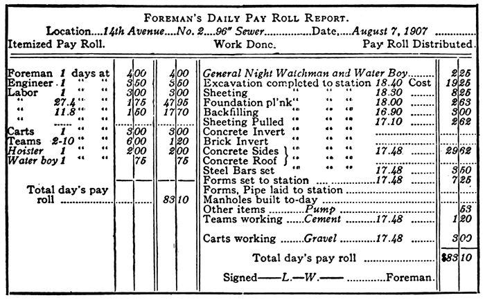
Fig. 86.—Foreman’s Daily Payroll Report. From Engineering and Contracting, 1907.
Materials may be recorded as they are delivered on the job, as they are used, or in both cases. Measurements are usually easier to make at the time of delivery, but records made at the time 237materials are used are more serviceable. For example, 100 barrels of cement may be delivered on a job in November, 50 of them are used before the job freezes up and the other 50 are held over until spring. It would be misleading to charge 100 barrels used in November. Fig. 87 is a form in use for an inspector’s report on materials. The total cost must be made up in the office from these records and a knowledge of unit costs.
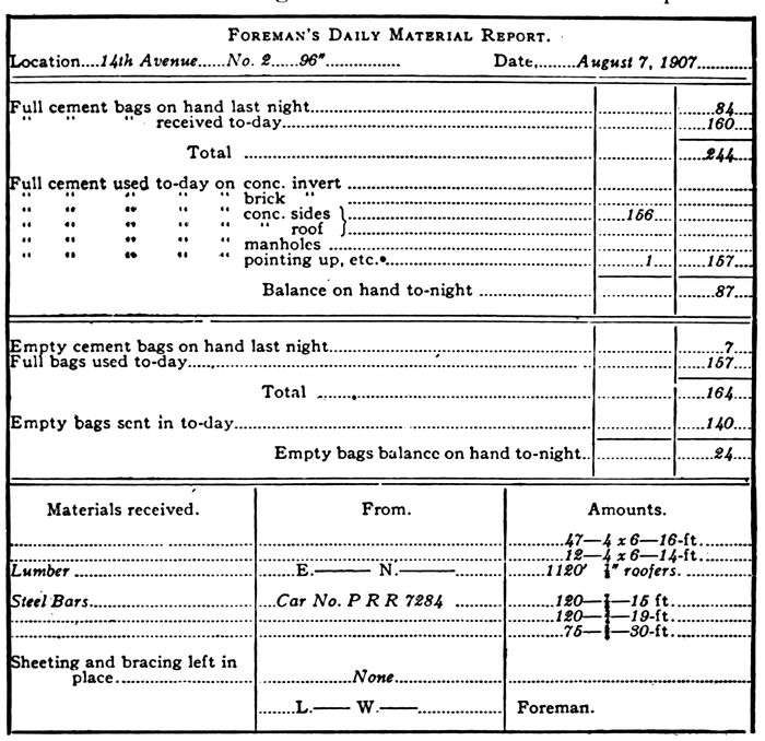
Fig. 87.—Foreman’s Daily Material Report. From Engineering and Contracting, 1907.
Equipment consists of tools, animals, machinery, and apparatus used in construction. Only equipment that is actually used should be charged to the job and a credit should be made at the completion of the job for the fair value of the equipment remaining after the completion of the work.
Overhead charges include the expense of the office force, superintendence, and miscellaneous items such as insurance, rent, 238transportation, etc., which cannot be charged to any particular portion of the work but are equally applicable to all portions. It happens frequently that many jobs are handled in the same main office. The division of overhead becomes more difficult and is frequently arranged on an arbitrary basis, e.g., each job may be charged the proportion of overhead that its contract price bears to the total contract prices being performed under that office. This rule may be modified when it becomes evident that some job is taking distinctly more than its share of the overhead.
Estimates of work done in any period can be made with the above data in hand by subtracting the total costs of the work up to the beginning of the period from the total costs up to the end of the period. Fig. 88 shows a sample blank from the final estimate sheets used at Scarsdale, N. Y.
124. Progress Reports.[80]—These are kept by the engineer in order that he may see that the work is progressing as called for in the contract, and any portion which is lagging behind without reason may be pushed. Such reports are most useful when the information is expressed graphically, as the eye quickly catches points where the work is falling behind schedule.
125. Records.—The contract drawings are supposed to show exactly where and how construction is to be done. Due to unexpected contingencies changes occur, of which a record should be made and preserved. These records may be kept in a form similar to the contract drawings, or if the changes are not extensive, they can be recorded on the original contract drawings. The location of house and other connections should be recorded in a separate note book available for immediate consultation. The engineer should keep a diary of the work in which are recorded events of ordinary routine as well as those of special interest and importance. This diary should be illustrated by photographs showing the condition of the streets before and after construction, methods of construction, accidents, etc. Such accounts are of great value in defending subsequent litigation and their existence sometimes prevents litigation. A contractor may wait a year or so after the completion of a piece of work until the engineer and other city officials have broken their connection with the city. Suit is then brought against the city and unless good records are available the administration may be forced to buy the claimant off or may elect to enter court, only to be beaten.
239
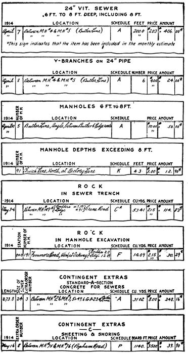
Fig. 88.—Samples of Cost Record Forms. From Engineering and Contracting, 1909.
240
Excavation
126. Specifications.—The following abstracts have been taken from the specifications on Excavation by the Baltimore Sewerage Commission as illustrative of good practice. In conducting the work the contractor shall:
... remove all paving, or grub and clear the surface over the trench, whenever it may be necessary and shall remove all surface materials of whatever nature or kind. He shall properly classify the materials removed, separating them as required by the Engineer; and shall properly store, guard, and preserve such as may be required for future use in backfilling, surfacing, repaving or otherwise. All macadam material removed shall be separated and graded into such sizes as the Engineer may direct and materials of different sizes shall be kept separate from each other and from any and all other materials.
All the curb, gutter, and flag-stones and all paving material which may be removed, together with all rock, earth and sand taken from the trenches shall be stored in such parts of the carriageway or such other suitable place, and in such manner as the Engineer may approve. The Contractor shall be responsible for the loss of or damage to curb, gutter and flag-stones and to paving material because of careless removal or wasteful storage, disposal, or use of the same.
... When so directed by the Engineer the bottom of the trench shall be excavated to the exact form of the lower half of the sewer or of the foundation under the sewer.
The bottom width of the trench for a brick or concrete sewer shall be ... not less in any case than the overall width of the sewer, as shown on the plans. In case the trench is sheeted this minimum width will be measured between the interior faces of the sheeting as driven, but in no case shall bracing, stringers, or waling strips be left within any portion of the masonry of the sewer except by permission of the Engineer; and such braces, stringers and waling strips shall not, in any case, be allowed to remain within the neat lines of the masonry as shown on the plans. In case that the distance between faces of the sheeting is less than that called for by the width of the 241sewer to be laid in the trench, the Engineer may direct the sheeting to be drawn and redriven, or otherwise changed and altered; or he may direct that the sewer be reinforced in such manner and to such an extent as he may deem necessary without compensation to the Contractor, even though such narrower trench was not caused by negligence or other fault on the part of the Contractor.
Trenches for vitrified pipe shall be at all points at least six inches wider in the clear on each side than the greatest external width of the sewer, measured over the hubs of the pipe.... Bell holes shall be excavated in the bottoms of trenches for vitrified pipe sewers wherever necessary.
Not more than three hundred feet of trench shall be opened at any one time or place in advance of the completed building of the sewer, unless by written permission of the Engineer and for a distance therein specified....
The excavation of the trench shall be fully completed at least twenty feet in advance of the construction of the invert, unless otherwise ordered.
During the progress of construction the Contractor will be required to preserve from obstruction all fire hydrants and the carriageway on each side of the line of the work.
The streets, cross-walks, and sidewalks shall be kept clean, clear, and free for the passage of carts, wagons, carriages and street or steam railway cars, or pedestrians, unless otherwise authorized by special permission in writing from the Engineer. In all cases a straight and continuous passageway on the sidewalks and over the cross walks of not less than three feet in width shall be preserved free from all obstruction.
Where any cross walk is cut by the trench it shall be temporarily replaced by a timber bridge at least three feet wide, with side railings, at the Contractor’s expense. The placing of planks across the trench without proper means of connection or fastenings, or pipe or other material, or the using of any other makeshift in place of properly constructed bridges, will not be permitted.
This is equally applicable to certain wagon bridges to be fixed upon by the Engineer, on the basis of traffic requirements.
In streets that are important thoroughfares or in narrow streets the material excavated from the first one hundred feet of any opening or from such additional length as may be required, shall upon the order of the Engineer, be removed by the Contractor, as soon as excavated. The material subsequently excavated shall be used to refill the trench where the sewer has been built.
242The preceding specifications are applicable to open-trench excavation. Rigid restrictions are placed about tunneling because of the greater difficulty of doing good work, the greater danger to life and property and the possibility of later surface subsidence if the backfilling is done improperly. A common clause in specifications is:
All excavations for sewers and their appurtenances shall be made in open trenches unless written permission to excavate in tunnel shall be given by the Engineer.
127. Hand Excavation.—Earth excavation by pick and shovel is the simplest and most primitive mode of excavation. Only small jobs are handled in this manner in order to save the investment necessary in machines or the expense of hiring and moving one to the work. The tools used in the hand excavation of trenches are: picks, pickaxes, long-handled and short-handled pointed shovels, square-edged long- and short-handled shovels, scoop shovels, axes, crowbars, rock drills, mauls, sledges, etc. The excavating gangs are divided up into units of 20 to 50 men under one foreman or straw boss, and among the men may be a few higher priced laborers who set the pace for the others. Each laborer on excavation should be provided with a shovel, the style being dependent on the character of the material being excavated and the depth of the trench. In stiff material and deep trenches requiring the lifting of the material in the shovel, long-handled pointed shovels should be used. In loose sandy material loaded directly into buckets short-handled, square pointed shovels are satisfactory. Picks are used in cemented gravels or where hard obstructions prevent cutting down with the edge of the shovel. Very stiff but not hard material can be cut out in chunks with a pickaxe and thrown from the trench or into a bucket with a scoop shovel. Scoop shovels are also useful in wet running quicksand. The number of picks, axes, crowbars, and other tools must be proportioned according to the material being excavated. Under the worst conditions of excavation in a hard cemented gravel it may be necessary to provide each man with a pick as well as a shovel, whereas in sand only a shovel is necessary. Two or three crowbars, axes, a length of chain, two or three screw jacks, etc., are provided per gang in case of an unexpected encounter with an obstruction in the trench, such as a boulder, a tree stump, a length of pipe, etc.
243In laying out the work the foreman marks the outlines of the trench on the ground by means of a scratch made with a pick, chalk marks, tape, or other devices. These marks are measured from offset or center stakes set by the engineer. Center stakes are less conducive to error but are more likely to be disturbed before use than are offset stakes, but careless foremen make more errors with offset than with center stakes. The inspector should assist or be present at the laying out of the trench. After the trench has been laid out each laborer should be given a certain specific portion of it to dig and this portion is marked out on the ground. In this way a check can be kept upon the performance of each laborer and the knowledge of this fact tends to a uniformly better performance. The amount of work that can be performed by one man with a pick and shovel is as shown in Table 49. Some men may exceed these rates, many will not attain them. The allotted task must be gaged on the character of the ground in order that the tasks may be equal and a spirit of competition fostered. The hard worker will set the pace for the lazy man. Some contractors have adopted the expedient of dismissing laborers for the day as soon as the allotted task is done.
TABLE 49
Amount of Material Moved by One Man with a Pick and Shovel
(From H. P. Gillette)
Material Cubic Yard per hour
Hardpan 0.33
Common earth 0.8 to 1.2
Stiff clay 0.85
Clay 1.00
Sand 1.25
Sandy soil 0.8 to 1.2
Clayey earth 1.3
Sandy soil (frozen) 0.75
The opening of the trench may be facilitated by breaking ground with a plow. In hard ground or on paved roads it may be necessary to cut through the surface crust with a hammer and drill, although in some cases a plow can be used successfully. Frozen ground can be thawed by building fires along the line of the trench, or greater economy may be achieved by placing steam pipes along the surface with perforations about every 18 inches 244and either boxing them on the top and sides or burying them in the frozen earth with a covering of sand. Another arrangement is to blow steam into a line of bottomless boxes in which each box is about 8 feet long. Holes are left in the top of the boxes into which the pipe is shoved, and after its withdrawal the holes are covered. Blasting of frozen earth is sometimes successful but cannot be resorted to in built up districts where it is unsafe unless properly controlled. Once the frost crust is broken through it can be attacked from below and frequently broken down by undermining.
A laborer cannot dig and raise the earth much more than to the height of his head, and preferably not quite so high, without tiring quickly. After the trench has passed a depth of 4 feet he cannot throw the earth clear of the trench. An additional laborer is needed then at the surface to throw the earth back. He should shovel the earth from a board platform placed at the edge of the trench as a protection to the bank. When the trench passes the 6–foot depth a staging is put in about 4 feet from the top on which the lowest laborer piles his materials. It is then passed up to the surface by a second laborer on the staging, and a third laborer on the surface throws the material back clear of the trench. Stagings are put in about every 5 or 6 feet for the full depth of the trench.
When the trench has come within half the diameter of the pipe of the final grade, if the material is sufficiently firm, the remainder of the trench should be cut to conform to the shape of the lower half of the outside of the pipe, with proper enlargements for each bell.
128. Machine Excavation.—On work of moderately large magnitude excavation by machine is cheaper than by pick and shovel alone. In comparing the cost of excavation by the two methods all items such as sheeting, pipe laying, backfilling, etc., should be included, since these items will be affected by the method of excavation. The cost of setting up and reshipping the machine must be included as this is frequently the item on which the use of the machine depends. Because of the cost of setting up and shipping, which must be distributed over the total number of yards excavated, the cost per cubic yard of excavating by machine varies with the number of cubic yards excavated. The point of economy in the use of a machine is reached when the cost by hand 245and by machine are equal. For all work of greater magnitude, excavation by machine will prove cheaper.[81] Items favoring the use of machinery which may cause its adoption for small jobs are: its greater speed, reliability, ease in handling, economy in sheeting, economy in labor, and small amount of space needed making it useful in crowded streets. Continuous bucket machines, drag lines, and occasionally steam shovels are not adapted to conditions where rocks, pipes and other underground obstacles are frequently met.
The following problem is an example of the work necessary in making a comparison of the relative economy of machine and hand excavation:
It is assumed that a man can excavate 15 feet of trench 30 inches wide and 8 feet deep in 10 hours. He receives 55 cents per hour for his work. A machine costing $10,000 has a life of 6 years. It can be kept busy 150 days in the year. When operating it costs $1.25 per hour for the operator, fuel and repairs. It will excavate 800 linear feet of 30 inch trench to a depth of 8 feet in 10 hours. It is assumed that capital is worth 10 per cent on such a venture and that the sinking fund will draw 10 per cent. If the cost of moving and setting up the machine is $1,800, how many cubic yards of excavation must there be to make excavation by machine economical? Costs of sheeting, pumping, etc., are assumed to be the same for machine or hand work.
Solution.—For hand work the man excavated 1.11 cubic yard per hour at 55 cents. The relative cost of hand excavation is then 50 cents per cubic yard.
The cost of machine work will be divided into: interest on first cost; operation and repairs; and sinking fund for renewal. The interest on the first cost of $10,000 at 10 per cent is $1,000 per year. The machine works 1,500 hours in the year. Therefore the cost per hour is $0.67.
The sinking fund payment, as found from sinking fund tables or the accumulation of $10,000 in. 6 years, is $1,300 per year or per hour for 1,500 hours is $0.87.
The cost of operation per hour is given as $1.25.
The total cost per hour is therefore $2.79.
The machine excavated 59.3 cubic yards per hour which makes the cost, exclusive of moving, equal to $0.47 246per cubic yard. In order to equalize the cost of machine and hand excavation the cost of moving the machine must be divided among a sufficient number of cubic yards so that the cost per cubic yard shall be 3 cents. The cost of moving is given as $1,800. This amount divided among 60,000 cubic yards equals 3 cents per cubic yard. Therefore the job must provide at least 60,000 cubic yards of excavation in order that the use of the machine shall be justifiable from the viewpoint of economy alone.
129. Types of Machines.—Machines particularly adapted to the excavation of sewer and water pipe trenches are of four types: (1) continuous bucket excavators; (2) overhead cableway or track excavators; (3) steam shovels; and (4) boom and bucket excavators. Other types of excavating machinery can be used for sewer trenches under special conditions. Machines are ordinarily limited to a minimum width of trench of 22 inches. Between widths of 22 inches and 36 inches the limit of depth for the first class of machines is about 25 feet. For other types of machines there is no definite limit, though the economical depth for open cut work seldom exceeds 40 feet.
130. Continuous Bucket Excavators.—Continuous bucket excavators are of the types shown in Figs. 89 and 90. The buckets which do the digging and raising of the earth may be supported on a wheel as in Fig. 89 or on an endless chain as in Fig. 90. The support of the wheel or endless chain can be raised or lowered at the will of the operator so as to keep the trench as close to grade as can be done by hand work. In some machines the shape of the buckets can be made such as to cut the bottom of the trench, in suitable material, to the shape of the sewer invert. In operation, the buckets are at the rear of the machine and revolve so that at the lowest point in their path they are traveling forward. The excavated material is dropped on to a continuous belt which throws it on the ground clear of the trench, into dump wagons, or on to another continuous belt running parallel with the trench to the backfiller, by means of which the excavated material is thrown directly into the backfill without rehandling. The body of the machine supporting the engine travels on wheels ahead of the excavation and is kept in line by means of the pivoted front axle. When obstacles are encountered the excavating wheel or chain is raised to pass over the obstacle, and allowed to dig itself in on the other side.
247
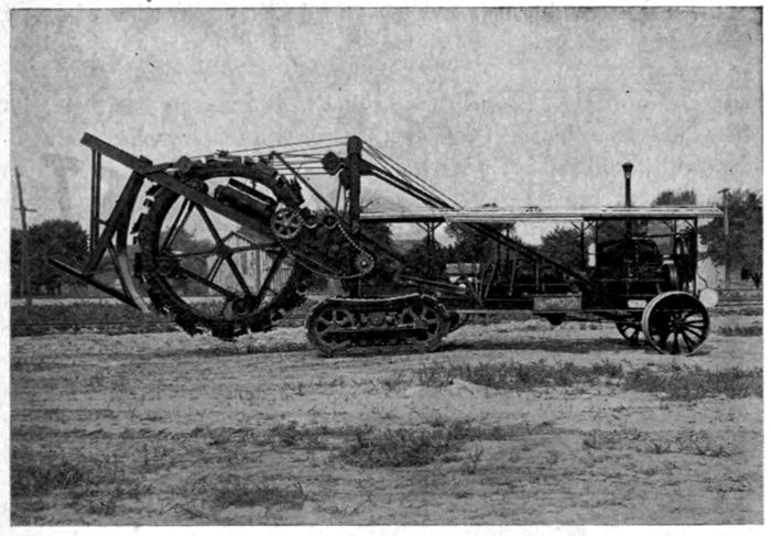
Fig. 89.—Buckeye Wheel Excavator. Courtesy, Buckeye Traction Ditcher Co.
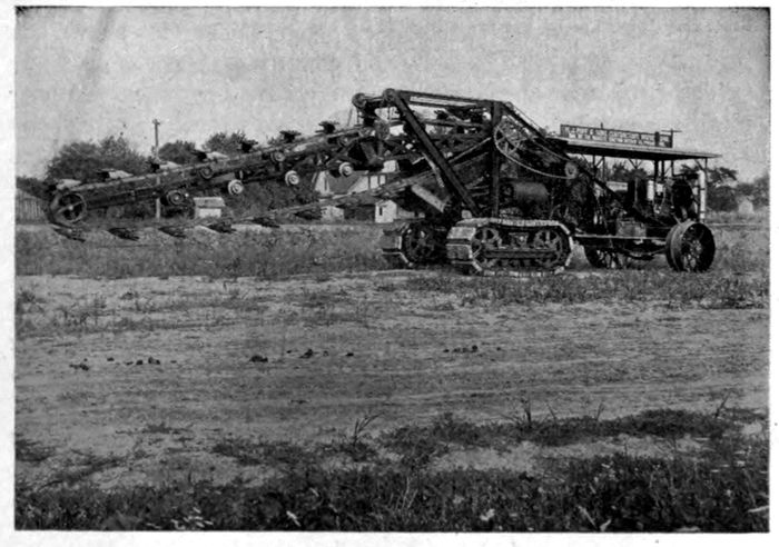
Fig. 90.—Buckeye Endless-chain Excavator. Courtesy, Buckeye Traction Ditcher Co.
248
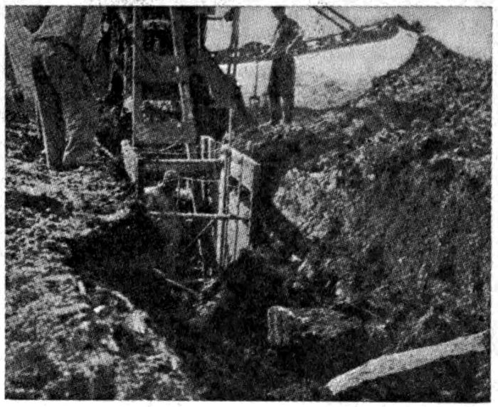
Fig. 91.—Movable Sheeting Fastened to Traction Ditcher. From Eng. News-Record, Vol. 82, 1919, p. 740.
Wheel excavators are not adapted to the excavation of sewer trenches over 3 to 4 feet in width and 6 to 8 feet in depth. The endless-chain excavators are suitable for depths of 25 feet with widths from 22 to 72 inches, and due to the arrangement permitting buckets to be moved sideways they will cut trenches of different widths with the same size buckets. This is an advantage where there are to be irregularities in the width of the trench such as for manholes or changes in size of pipe. With excavating machines pipe can be laid within 3 feet of the moving buckets and the trench backfilled immediately, thus making an appreciable saving in the amount of sheeting. In the construction of trenches for drain tile at Garden Prairie, Illinois, the sheeting was built in the form of a box or shield fastened to the rear of the machine and pulled along after it as is shown in Fig. 91.
The performance of this type of excavating machine under suitable conditions is large. A remarkable record was made by Ryan and Co. in Chicago,[82] with an excavating machine. 1338 feet of 32–inch trench were excavated to an average depth of 8½ feet in 7 hours, or an average of 160 cubic yards per hour. More could have been accomplished if it had not been for delays in supplies. Another crew at Greeley, Colorado,[83] with a Buckeye endless-chain ditcher weighing 17 tons and costing $5200, averaged 232 cubic yards per day for 300 days, and the cost was 10.7 cents per cubic yard. A 15–ton Austin excavator can be expected to remove 300 to 500 cubic yards per day.
The cost of operation of the machines is made up of items listed in Table 50. The figures given are merely suggestive.
249
TABLE 50
Cost of Operating Ditching Machine
Per Day Total
Labor:
1 Operator at $150 per month $6.00
1 Assistant Operator at $120 per month 4.00
4 laborers at 4.00 per day 16.00
$26.00
Fuel:
20 Gallons of gasoline at 28 cents 5.60 5.60
Miscellaneous:
Oil, waste, etc. 1.20
Repairs and maintenance 10.00
Interest, 6 per cent on $10,000 for 150 days 4.00
Depreciation, 200 working days per year and an 8 year life 11.11 26.31
Total cost per day $57.91
TABLE 51
Comparison of Cost of Hand Excavation and Machine Excavation with Continuous-bucket Excavator
Hand Work Per Day, Dollars Machine Work Per Day, Dollars
Foreman 4.00 Engineer 4.00
Timberman 3.00 Fireman 2.50
Helper 2.50 Coal 5.00
4 Laborers at $2.00 80.00 Team 4.00
Foreman 4.00
Pipe layer 3.00
Helper 2.50
2 Teams backfilling 8.00
2 Helpers 4.00
Interest, depreciation and repairs 10.00
Total 95.00 Total 54.50
250In making a comparison of the cost of hand and machine excavation the figures given in Table 51 are from “Excavating Machinery” by McDaniel, who quotes the cost of machine excavation from the manufacturers of the Parsons machine issued as the result of several years’ experience with their excavator. In the comparison the hand crew is assumed to dig 315 linear feet of trench 28 inches wide by 12 feet deep in a day of 10 hours. This assumes that each man will excavate 7 cubic yards per day. The machine is assumed to excavate 250 feet of the same trench. The comparison indicates that an excavator will work at about 50 per cent of the cost of hand excavation, if the cost of moving the machine is not included.
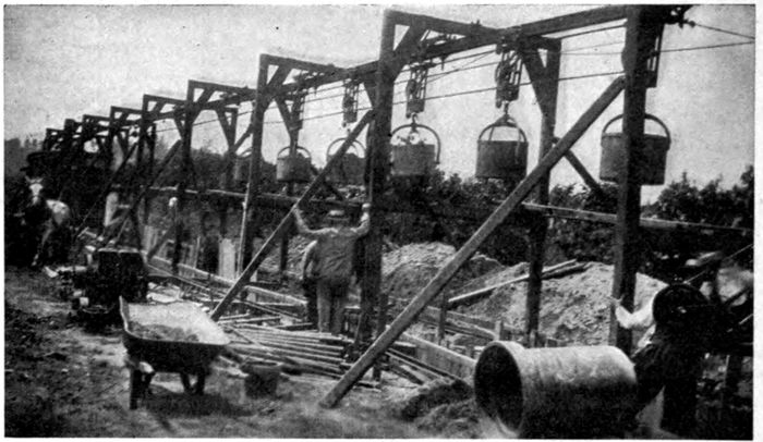
Fig. 92.—Carson Excavating Machine on Trench Excavation in South Milwaukee. Courtesy, Mr. C. F. Henning.
131. Cableway and Trestle Excavators.—Cableway and trestle excavators are most suitable for deep trenches and crowded conditions. They should not be used for trenches much less than 8 feet in depth. They differ from the continuous bucket excavators in that the actual dislodgment of the material is done by pick and shovel, the excavated material being thrown by hand into the buckets of the machine. A machine of the Carson type is shown in Fig. 92. The machine consists of a series of demountable frames held together by cross braces and struts to form a semirigid structure. An I beam or channel extending the length of 251the machine is hung closely below the top of the struts. The lower flange of this beam serves as a track for the carriages which carry the buckets. All the carriages are attached to each other and to an endless cable leading to a drum on the engine. This cable serves to move the buckets along the trench. The buckets are attached to another cable which is wound around another drum on the engine and serves to lower or raise all the buckets at the same time. In operation there are always at least two buckets for each carriage, one in the trench being filled and the other on the machine being dumped. There should be a surplus of buckets to replace those needing repairs.
The machines may be from 200 to 350 feet in length, and the number of buckets which can be lifted at one time varies from one to a dozen or more. On trenches over 5 to 6 feet in width a double line of buckets is sometimes used. The entire machine rests on rollers and straddles the trench. It is moved along the trench by its own power, either by gearing or chains attached to the wheels, or by a cable attached to a dead-man ahead.
The Potter trench machine differs from the Carson in that only 2 buckets are used at a time and these are carried on a car which travels on a track on top of the trestle. The movement of the buckets and the car are controlled by 2 dump men who ride on the car and who can raise or lower the buckets independently.
The organization needed to operate these machines is: a lockman who locks and unlocks the buckets on the cable, a dumper, as many shovelers as there are buckets on the machine, and an engineman who is usually his own fireman. From 50 to 400 cubic yards of material can be excavated in a day with one of these machines, dependent on the character of the material and the depth of the trench. H. P. Gillette in his Handbook of Cost Data reports that about 190 cubic yards were excavated per day with a Potter machine. The machine was 370 feet long. Six ¾-yard buckets were used, 4 in the trench and 2 on the carrier. The trench was 10½ feet wide and 18 feet deep in wet sand and soft blue clay. The organization consisted of an engineman, a fireman, 2 dumpmen on the carrier, and from 17 to 21 excavating laborers depending on the kind and the amount of the excavation. In general the capacity of such machines is limited by the amount of material which can be shoveled into them by hand.
252132. Tower Cableways.—These are essentially of the same class as the trestle cableway machines. They differ in that the carriage supporting the buckets travels on a cable suspended between 2 towers instead of on a track supported on a trestle. As a rule only one bucket is handled in the machine at a time. They are used in sewer work only in exceptional cases as the towers must be taken down and re-erected each time that there is an advance in the trench greater than the distance between the towers.
133. Steam Shovels.—The use of steam shovels for the excavation of sewer trenches is becoming more prevalent because of their growing dependability and durability as compared with other machines, their adaptability for small trenches, and the relatively large number of widely different uses to which they can be put. In excavating a trench the shovel straddles the trench and runs on tractors, wheels, or rollers on either side of it. The shovel cuts the trench ahead of it. As a result it is difficult to set sheeting and bracing close to the end of the trench while the shovel is operating. Steam shovels are therefore not suitable for excavation in unstable material, unless the sheeting is driven ahead of the excavation. It is only in the softest ground that ordinary wood sheeting can be driven ahead of the excavation. Steel sheet piling is more suitable for such use. Fig. 93[84] shows a shovel at work on a trench in Evanston, Illinois.
Shovels are equipped with extra long dipper handles to adapt them to trench excavation. The dipper handle in the picture is longer than the standard for this type of machine. The method of supporting the shovel can be seen in the picture under the machine and the method of bracing and of finishing the trench by hand work are also shown. The excavated material is taken out in the shovel and dropped on the bank or into wagons.
The limiting depth to which trenches can be excavated by steam shovels is about 20 to 25 feet, where the trench is too narrow for the shovel to enter. Wider trenches are cut in steps of about 15 feet, the shovel working in the trench for additional depths. Shovels are now made to cut trenches as narrow as a man can enter to lay pipe. The greatest width that can be cut from one position of the shovel is from 15 to 40 feet, dependent on the size of the shovel. Occasionally a combination of a drag line 253and a steam shovel can be used, as on the construction of the Calumet sewer in Chicago. On this work the first step was cut by a steam shovel. It was followed by a drag line resting on the step thus prepared, and excavating the remaining distance to grade. The depth of the trench in this work averaged about 25 to 30 feet.
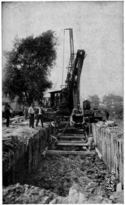
Fig. 93.—Steam Shovel at Work on Sewer Trench for North Shore Intercepting Sewer, Evanston, Illinois.
Steam shovels are rated according to their tonnage and the capacity of the dipper in cubic yards. Both are necessary as the size of the dipper is varied for the same weight of machine, dependent on the character of the material being excavated. For rock the dipper is made smaller than for sand. Gillette in his Hand Book of Cost Data gives the coal and water consumption of steam shovels as shown in Table 52. The performance of steam shovels is recorded in Table 53. The conditions of the work have a marked effect on the output of the shovel. A shovel in a thorough cut, i.e., in a trench just wide enough for the shovel to turn 180 degrees but too narrow to run cars or wagons along side of it, will perform less than one-half of the work that it can perform in a side cut, i.e., where the cars can be run along side the shovel which turns less than 90 degrees.
254
TABLE 52
Coal and Water Consumption by Steam Shovels
(From Handbook of Cost Data, by H. P. Gillette)
Weight in tons 35 45 55 65 75 90
Dipper, cubic yards 1¼ 1½ 1¾ 2 2½ 3
Coal, tons per 10 hour day ¾ 1 1¼ 1½ 2 2¼
Water, gallons per 10 hour day 1500 2000 2500 3000 4000 4500
TABLE 53
Performance by Steam Shovels
Weight in Tons Dipper Cubic Yards Depth of Cut, Feet Width of Cut 10–Hour Performance Cost in Cents, per Cubic Yard Authority Remarks
25 1 9 36 in. 85 22.6 R. T. Dana Eng. Rec., 69:581 1
25 1 8 35 in. 96 23.5 do. 2
70 2 26 16 ft. 569 6.7 do. 3
30 1 15–18 60 in. 300 A. B. McDaniel Excavating Machinery 4
15 ⅝ 14 134 ft. 400 Eng. Cont’r, 8–25–09 5
8 36 Very wide 16 yd. cars Marion Steam Shovel Co. 6
55 296 H. P. Gillette’s Cost Data 7
65 2¼ 280 do.
Greater than 78 in. 700 30.6 G. C. D. Lenth, Eng. News-Record, 85:22 8
Remarks:
1.
One runner at $5.00, one fireman at $2.31, two laborers at $1.70 each, supplies at $4.50, and interest and depreciation on 200 days per year, $4.00. Total per day, $19.21. Material, clay and gravel.
2.
Average of 11 jobs with the same shovel.
3.
Cost per day, one runner at $5.00, one crane-man at $3.60, one fireman at $2.00, 7 roller men at $1.50 each, supplies $9.00 and interest and depreciation on $9000 at 200 days per year $8.00. Total, $38.10.
4.
Hard clay.
5.
Stiff clay for the basement of a building in Chicago.
6.
Stripping ore. This is a maximum record. The average was about three hundred and twenty 16 cubic yard cars per day.
7.
Blasted mica-schist.
8.
General average.
255134. Drag Line and Bucket Excavators.—A drag line excavator is shown in Fig. 94. The back of the bucket is attached to a drum on the engine by means of a cable passing over the wheel in the end of the long boom. The front of the bucket is attached by another cable directly to another drum on the engine. In operation the bucket is raised by its rear end and dropped out to the extremity of the boom. It is then dragged over the ground towards the machine, digging itself in at the same time. When filled the bucket is raised by tightening up on the two cables, swung to one side by means of the movable boom, and dumped.
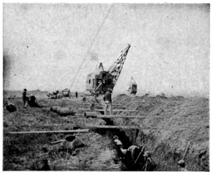
Fig. 94.—Drag Line at Work on Trench for Drain Tile.
Drag line excavators will perform as much work as steam shovels under favorable conditions. They are less expensive in first cost and operation, and are equally reliable but they are not adapted to the more difficult situations where steam shovels can be used to advantage. Drag lines are suitable only for relatively wide trenches in material requiring no bracing, and in a locality where relatively long stretches of trench can be opened at one time.
The bucket excavator differs from the drag line in that the bucket can be lifted vertically only and the types of buckets used in the two types of machine are different. The bucket may be self filling of the orange-peel or clam-shell type, or a cylindrical container which must be filled by hand. A drag line can be 256easily converted into a boom and bucket excavator. Boom and bucket excavators are well adapted to use in deep, closely braced trenches and shafts.
135. Excavation in Quicksand.[85]—A sand or other granular material in which there is sufficient upward flow of ground water to lift it, is known as quicksand. Its most important property, from the viewpoint of sewer construction, is its inability to support any weight unless the sand is so confined as to prevent flowing of the sand, or unless the water is removed from the sand.
Excavation in quicksand is troublesome and expensive and is frequently dangerous. The material will flow sluggishly as a liquid, it cannot be pumped easily, and its excavation causes the sides of the trench to fall in or the bottom to rise. The foundations of nearby structures may be undermined, causing collapse and serious damage. These conditions may arise even after the backfilling has been placed unless proper care has been taken. The greatest safeguard against such dangers is not only to exercise care in the backfilling to see that it is compactly tamped and placed, but to leave all sheeting in position after the completion of the work.
The ordinary method of combating quicksand and in conducting work in wet trenches is to drive water-tight sheeting 2 or 3 feet below the bottom of the trench, and to dewater the sand by pumping. When dry it can be excavated relatively easily. A more primitive but equally successful method is to throw straw, brickbats, ashes, or other filling material into the trench in order to hold the excavation once made, or this may supplement the attempts at pumping, or the wet sand may be bailed out in buckets. Successful excavation in quicksand requires experience, resourcefulness. and a careful watch for unexpected developments. The well points described in Art. 142 are used for dewatering quicksand.
136. Pumping and Drainage.—Ground water is to be expected in nearly all sewer construction and provision should be made for its care. Where geological conditions are well known or where previous excavations have been made and it is known that no ground water exists it may be safe to make no provision for encountering ground water. Where ground water is to be expected 257the amount must remain uncertain within certain rather wide limits until actually encountered.
In order to avoid the necessity for pumping, or working in wet trenches it is sometimes possible to build the sewer from the low end upwards and to drain the trench into the new sewer. The wettest trenches are the most difficult to drain in this manner as the material is usually soft and the water so laden with sediment as to threaten the clogging of the sewer. It is undesirable to run water through the pipes until the cement in the joints has set. This necessitates damming up the trench for a period which may be so long as to flood the trench or delay the progress of the work. If it is not possible to drain the trench through the sewer already constructed the amount of water to be pumped can be reduced by the use of tight sheeting.
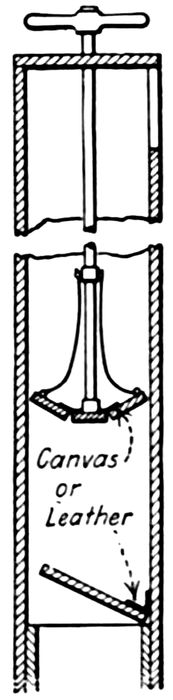
Fig. 95. Improvised Trench Pump.
Pumps for dewatering trenches must be proof against injury by sand, mud, and other solids in the water. For this purpose pumps with wide passages and without valves or packed joints are desirable. The types of pumps used are: simple flap valve pumps improvised on the job, diaphragm pumps, jet pumps, steam vacuum pumps, centrifugal pumps, and reciprocating pumps. All are of the simplest of their type and little attention is paid to the economy of operation because of the temporary nature of their service.
137. Trench Pump.—A simple pump which can be improvised on the job is shown in section in Fig. 95. Its capacity is about 20 gallons per minute but its operation is backaching work. It is inexpensive, quickly put together and may be a help in an emergency. It is to be noted that the passages are large and straight, that there are no packed joints, and that the velocity of flow is so small that it is not liable to clogging by picking up small objects.
258
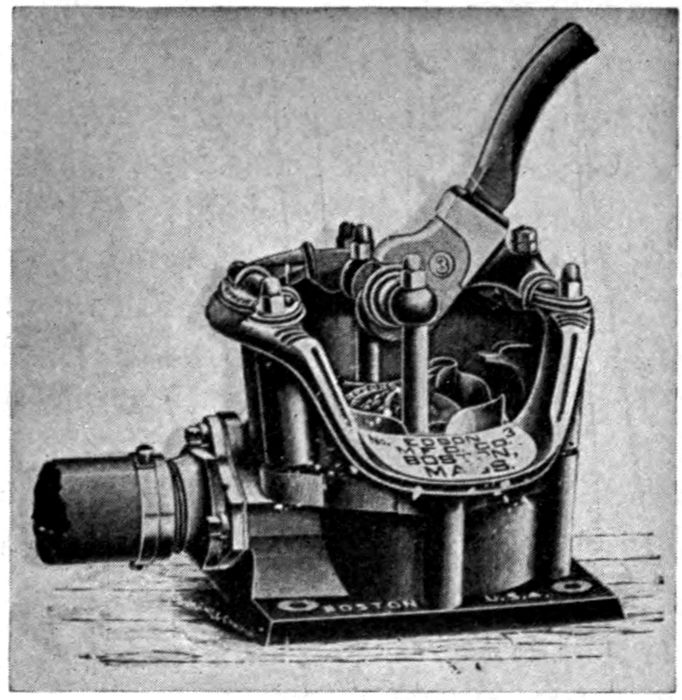
Fig. 96.—Diaphragm Pump Courtesy, Edson Manufacturing Co.
138. Diaphragm Pump.—The type of pump shown in Fig. 96 is the most common in use for draining small quantities of water from excavations. It is known as the diaphragm pump from the large rubber diaphragm on which the operation depends. The pump is made of a short cast-iron cylinder, divided by the rubber diaphragm or disk to the center of which the handle is connected. The valve is shown at the center of the disk. As the diaphragm is lifted the valve remains closed, creating a partial vacuum in the suction pipe and at the same time discharging the water which passed through the valve on the previous down stroke. When the valve is lowered the foot valve on the suction pipe closes, holding the water in place, and the valve in the pump opens allowing the water to flow out on top of the disk to be discharged on the next up stroke. Table 54 shows the capacities of some diaphragm pumps as rated by the manufacturers. The smaller sizes are the more frequently used and are equipped with a 3–inch suction hose with strainer and foot valve. They are not adapted to suction lifts over 10 to 12 feet. Where greater lifts are necessary one pump may discharge into a tub in which the foot valve of a higher pump is submerged.
TABLE 54
Capacities of Diaphragm Pumps
Diameter of Cylinder, Inches Diameter of Suction, Inches Length of Stroke in Inches Capacity per Stroke, Gallons
6 3 4 0.49
8½ 4 6 1.47
9[86] 2½ 0.75
12½[86] 3 1.25
259
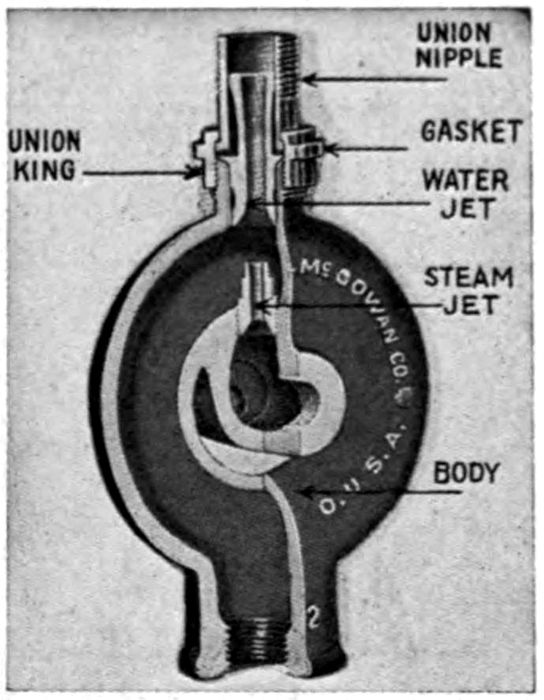
Fig. 97.—McGowan Steam Jet Pump. Courtesy, The John H. McGowan Co.
139. Jet Pump.—The simplicity of the parts of the jet pump is shown in Fig. 97. It has a distinct advantage over pumps containing valves and moving parts in that there are no obstructions offered to the passage of solids as well as liquids through the pump. It is not economical in the use of steam, however. It operates by means of a steam jet entering a pipe at high velocity through a nozzle. This action causes a vacuum which will lift water from 6 to 10 feet. The lower the suction lift, however, the greater the efficiency of the work. The sizes and capacities of jet pumps as manufactured by the J. H. McGowan Co. are shown in Table 55.
TABLE 55
Capacities of Jet Pumps
(J. H. McGowan Co.)
Size of Pump and Suction Pipe, Inches Discharge Pipe, Inches Steam Pipe, Inches Capacity, Gallons per Minute Approximate Horse-power Required
¾ ½ ⅜ 8 2
1 ¾ ½ 15 3
1¼ 1 ½ 20 4
1½ 1¼ ¾ 30 6
2 1½ ¾ 40 8
2½ 2 1 50 10
3 2½ 1 60 15
4 3½ 1¼ 85 25
140. Steam Vacuum Pumps.—This type of pump depends on the condensation of steam in a closed chamber to create a vacuum which lifts water into the chamber previously occupied by the 260steam and from which the water is ejected by the admission of more steam. The best known pumps of this type are the Pulsometer, manufactured by the Pulsometer Steam Pump Co., the Emerson, manufactured by the Emerson Pump and Valve Co., and the Nye Pump, manufactured by the Nye Steam Pump and Machinery Co.
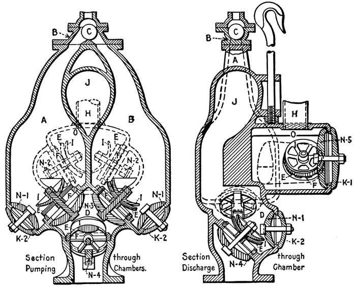
Fig. 98.—Pulsometer Steam Vacuum Pump.
A section of a Pulsometer is shown in Fig. 98. It consists of two bottle-shaped chambers A and B with their necks communicating at the top and each opening into the outlet chamber O through a check valve. Steam is admitted at the top and enters chamber A or B according to the position of the steam valve C as shown. This steam valve is a ball which is free to roll either to the right or left and forms a steam-tight joint with whichever seat it rests upon. In normal operation chamber A would be filled with water as the steam enters the cylinder. At the same time a check valve at the top opens to admit a small quantity of air which forms a cushion insulating the steam from the water, reduces the condensation of the steam, and serves as a cushion 261for the incoming water on the opposite stroke. The pressure of the steam depresses the surface of the water without agitation and forces the water through the check valve F into the discharge chamber O. When the water falls to the level of the discharge chamber the even surface is broken up and the intimate contact of the steam and water condenses the former instantaneously. This forms a vacuum in chamber A which, assisted by a slight upward pressure in chamber B caused by the incoming water, immediately pulls the ball C over to the other seat and directs the steam into chamber B. The vacuum in chamber A now draws up a new charge of water through the suction pipe into the chamber.
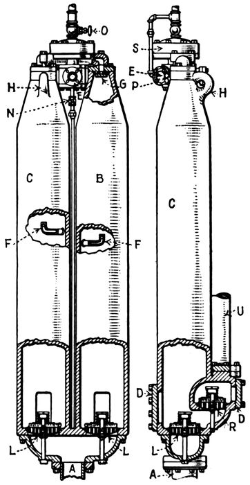
Fig. 99.—Emerson Steam Vacuum Pump.
A section of the Emerson pump is shown in Fig. 99. The pump consists of two vertical cylinders B and C. Each chamber has a suction valve L at the bottom, opening upward from a common chamber from which the discharge pipe U extends. On the top of each chamber is a baffle plate G which operates to distribute the steam evenly to the two chambers and to prevent it from agitating the surface of the water in the chambers. A condenser nozzle F is connected with the bottom of the opposite chamber by a pipe into which a check valve opens upward. As the pressure in the chamber alternates water will be injected through F into the opposite chamber and condense the steam therein, promptly forming a vacuum. An air valve P admits a small quantity of air while the chamber is filling with water, the air acting as an insulating cushion as in the Pulsometer. Valve O, just above the top connection S is used to regulate the amount of steam that 262enters the pump. The top connection S has two ports, one leading to each chamber. An oscillating valve enclosed in it admits the steam through these ports to the two chambers alternately. This valve is driven by a small three-cylinder engine, the crank shaft of which extends into the top connection in the center of the bearing on which the valve oscillates. A positive geared connection is made between the valve and the engine and so arranged that the engine will run faster than the valve.
The action of these pumps consists of alternately filling and emptying the two chambers. They will continue operation without attention or lubrication so long as the steam is turned on. In view of the simplicity of their operation and make-up, their ability to handle liquids heavily charged with solids, and their reasonable steam consumption these pumps are widely used for pumping water in construction work. They have an added advantage that no foundation or setting is required for them as they can be hung by a chain from any available support.
These pumps are manufactured in sizes varying from 25 to 2500 gallons per minute at a 25–foot head, and with a steam consumption of about 150 pounds per horse-power hour. They reduce about 4 per cent in capacity for each 10 feet of additional lift. They will operate satisfactorily between heads of 5 to 150 feet, with a suction lift not to exceed 15 feet. Lower suction lifts are desirable and the best operation is obtained when the pump is partly submerged. The steam pressure should be balanced against the total head. It varies from 50 to 75 pounds for lifts up to 50 feet, and increases proportionally for higher lifts. The dryer the steam the lower the necessary boiler pressure.
141. Centrifugal and Reciprocating Pumps.—The details of these pumps, their adaptability to various conditions, and their capacities are given in Chapter VII. The centrifugal is better adapted to trench pumping as it is not so affected by water containing sand and grit, but for clear water, high suction lifts and fairly permanent installations, reciprocating pumps can be used with satisfaction.
142. Well Points.—In dewatering quicksand a method frequently attended with success is to drive a number of well points into the sand and connect them all to a single pump. Figure 100 shows a well point system used on sewer work in Indiana. The well points are 3 feet apart and are connected to a 2½-inch header 263which in turn is connected to six Nye pumps, each with a capacity of 200 gallons per minute for a lift of 50 feet. The number and size of well points and pumps to use will depend on conditions as met on the job. On a piece of work in Atlantic City[88] the equipment consisted of two complete outfits each comprising one hundred 1½ inch by 36–inch No. 60 well points, one hundred 6–foot lengths of rubber hose, about 600 feet of suction main, one hundred valved T connections, and a 7 × 8–inch Gould Triplex Pump with a capacity of 200 gallons per minute, belted to a 7½ horse-power motor.
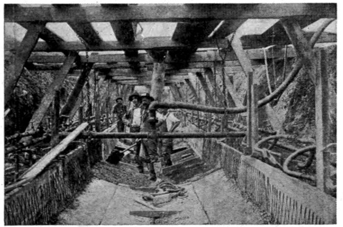
Fig. 100.—Well Points Pumped by Nye Steam Vacuum Pump.
143. Rock Excavation.—A common definition of rock used in specifications is: whenever the word Rock is used as the name of an excavated material it shall mean the ledge material removed or to be removed properly by channeling, wedging, barring, or blasting; boulders having a volume of 9 (this volume may be varied) cubic feet or more, and any excavated masonry. No soft disintegrated rock which can be removed with a pick, nor loose shale, nor previously blasted material, nor material which may have fallen into the trench will be measured or allowed as rock.
Channeling consists in cutting long narrow channels in the rock to free the sides of large blocks of stone. The block is then loosened by driving in wedges or it is pried loose with bars. It is a method used more frequently in quarrying than in trench excavation 264where it is not necessary to preserve the stone intact. In blasting, a hole is drilled in the rock, and is loaded with an explosive which when fired shatters the rock and loosens it from its position.
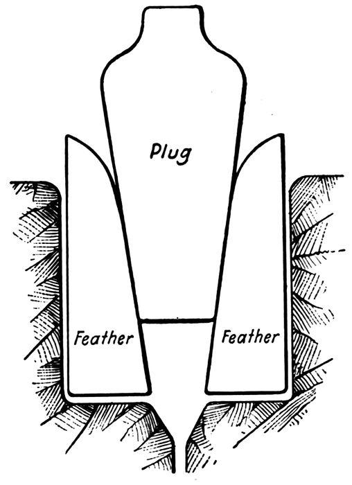
Fig. 101.—Plug and Feathers for Splitting Rock.
In drilling rock by hand the drill is manipulated by one man who holds it and turns it in the hole with one hand while striking it with a hammer weighing about 4 pounds held in the other hand, or one man may hold and turn the drill while one or two others strike it with heavier hammers. In churn drilling a heavy drill is raised and dropped in the hole, the force of the blow developing from the weight of the falling drill. Hand drills are steel bars of a length suitable for the depth of the hole, with the cutting edge widened and sharpened to an angle as sharp as can be used without breaking. The drill bar is usually about ⅛th of an inch smaller than the diameter of the face of the drill.
Wedges used are called plugs and feathers. They are shown in Fig. 101 which shows also the method of their use. The feathers are wedges with one round and one flat face on which the flat faces of the plug slide.
144. Power Drilling.—In power drilling the drill is driven by a reciprocating machine which either strikes and turns the drill in the hole, or lifts and turns it as in churn drilling, or the drill may be driven by a rotary machine which is revolved by compressed air, steam, or electricity. There are many different types of machines suitable for drilling in the different classes of material encountered and for utilizing the various forms of power available.
A jack hammer drill is shown in Fig. 102. In its lightest form the drill weighs about 20 pounds and is capable of drilling ⅞-inch holes to a depth of 4 feet. Heavier machines are available for drilling larger and deeper holes. The same machine can be adapted to the use of steam or compressed air. When in use the point of the drill is placed against the rock and a pressure on the 265handle opens a valve admitting air or steam. The piston is caused to reciprocate in the cylinder, striking the head of the drill at each stroke. The drill is revolved in the hole by hand or by a mechanism in the machine. A hollow drill can be used by means of which the operator admits air or steam to the hole, thus blowing it out and keeping it clean. These machines have the advantage of small size, portability and simplicity. They can be easily and quickly set up and the drills can be changed rapidly. Their undesirable features are the vibration transmitted to the operator and the dust raised in the trench.
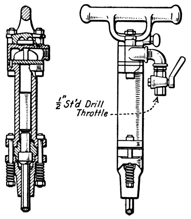
Fig. 102.—Jack Hammer Rock Drill.
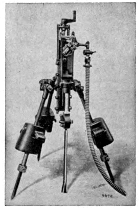
Fig. 103.—Tripod Drill.
A type of drill heavier and larger than the jack hammer drill is shown in Fig. 103. It requires some form of support such as a tripod, or in tunnel work it can be braced against the roof or sides. Some data on steam and air drills are given in Table 56. The effect of the length of the transmission pipe, temperature of the outside air, pressure at the boiler or compressor, etc., will have a marked effect on the amount of steam or air to be delivered to the drill. Compressed air is affected more than steam by these outside factors, but it has an advantage in that as it loses in pressure it increases in volume so that the loss of power is not so marked. Gillette states:
266We may assume that a cubic foot of steam will do practically the same work in a drill as a cubic foot of compressed air at the same pressure, because neither the steam nor the air acts expansively to any great extent in a drill cylinder, due to the late cut-off. This being so ... one pound of steam is equivalent to nearly 30 cubic feet of free air ... all at the same pressure of 75 pounds per square inch. If a drill consumes at the rate of 100 cubic feet of free air per minute ... it would therefore consume 240 pounds of steam (at 75 pounds pressure) per hour.... Where not more than three or four drills are to be operated, probably no power can equal compressed air generated by gasoline. It will require 12 horse-power to compress air for each drill, hence 1½ gallons of gasoline will be required per hour per drill while actually drilling.
TABLE 56
Data on Rock Drills
(From H. P. Gillette)
Diameter of cylinder in inches 2¼ 2½ 2¾ 3⅛ 3¼ 3⅜
Length of stroke in inches 5 6 6½ 6⅝ 6⅝ 7¼
Length of drill from end of crank to end of piston 36 43 50 50 50 52
Depth of hole drilled without change of bit, inches 15 20 24 24 24 24
Diameter of supply inlet. Standard pipe, inches ¾ ¾ ¾ 1 1 1¼
Approximate strokes per minute with 60 pound pressure at the drill 500 450 375 350 325 300
Depth of vertical hole each machine will drill easily, feet 6 8 10 14 16 20
Diameter of holes drilled, inches ¾ to 1½ as desired
Diameter of octagon steel, inches ¾ to ⅞ ⅞ to 1 1 to 1⅛ 1⅛ to 1¼ 1⅛ to 1¼ 1¼ to 1⅜
Best size of boiler to give plenty of steam at high pressure, horse-power 6 8 8 9 10 12
Best size of supply pipe to carry steam 100 to 200 feet, inches ¾ ¾ ¾ 1 1 1¼
Weight of drill unmounted, with wrenches and fittings, hot boxed, pounds 128 190 265 315 385 390
Weight of tripod, without weights, not boxed, pounds 80 160 160 160 210 275
Weight of holding down weights, not boxed, pounds 120 270 270 285 330 375
Cubic feet of free air per minute required to run one drill at 100 pounds 92 104 126 146 154 160
For more than one drill, multiply the value in the above line by the following factors: For 2 drills, 1.8; 5 by 4.1; 10 by 7.1; 15 by 9.5; 20 by 11.7; 30 by 15.8; 40 by 21.4; 70 by 33.2.
267Since gasoline air compressors are self regulating, when the drill is not using air very little gasoline is burned by the gasoline engine driving the compressor. A gasoline compressor possesses other very important economic advantages over a small steam-driven plant. First, there is the saving in wages of firemen and second, there is the saving in hauling and pumping of water and the hauling of fuel. The cost of gasoline is often less than the cost of coal for operating a small plant.
An electric drill[89] operated on the principle of the solenoid does away with motor, valves, pipes, vapor, freezing, and other difficulties attendant on the use of steam or air.
The rates of drilling in different classes of rock are shown in Table 57. Frequent changes of drills and relocation of tripods will materially reduce the performance of a drill, for as much as 45 minutes may be lost in making a new set up. In this the jack hammer drills show their advantage as no time is lost in a set up.
TABLE 57
Rates of Rock Drilling
Rates in Feet per Ten-hour Shift. Vertical Holes 10–20 Feet Deep.
(From Gillette)
Hard Adirondack granite 48
Maine and Massachusetts granite 45–50
Mica-schist of New York City. Possible 60–70
Mica-schist of New York City. Average 40–50
Hard, Hudson River trap rock 40
Soft red sand stone of Northern New Jersey 90
Hard limestone near Rochester, N. Y 70
Limestone of Chicago Drainage Canal 70–80
Douglass, Indiana, syenite. Difficult set ups 36
Canadian granite on Grand Trunk R. R 30
Windmill point, Ontario limestone:
3⅝-inch drills 75
2¾-inch drills 60
2¼-inch drills 37
145. Steam or Air for Power.—The choice between steam or air is dependent on the conditions of the work. Steam is undesirable in tunnels on account of the heat produced. In open cut 268work it is at a disadvantage because of the loss of power due to radiation from the hose or pipe. The life of the hose is not so long as when air is used, escaping steam causes clouds of vapor which obscure the work, and serious burns may occur due to hot water thrown from the exhaust. It is advantageous since leaks may be easily discovered and remedied, it requires less machinery than air, and it is sometimes less expensive. With compressed air, gasoline or electric motors can be used for operating the compressors.
TABLE 58
Rock Blasting
(From Gillette)
Character of Material Powder Used per Hole Depth of Hole, Feet Distance Back of Face, feet Distance Hole to Hole, feet
Limestone of Chicago Drainage Canal 40 per cent dynamite 12 8 8
Sandstone 200 pounds black powder 20 18 14
Granite 2 pounds 60 per cent dynamite 12 1½ 4½ to 5
Pit mining, Treadwell, Mine, Alaska 12 2½ 6
146. Depth of Drill Hole.—The depth of the hole is dependent on the character of the work. The deepest holes can be used in open cut work where the shattered rock is to be removed by steam shovel. The face can be made 10 to 15 feet high. The depth of the hole in center cut tunnel facings are from 6 to 10 or even 12 feet. In the bench the depth is equal to the height of the bench. In narrow trenches where the rock is to be removed by derrick or thrown into a bucket by hand, the hole should be sufficiently deep to shatter the rock to a depth of at least 6 inches below the finished sewer. Frequently shooting to this depth at one shot cannot be done due to the built up condition of the neighborhood or other local factors. The depth of the hole in trench work should not much exceed the distance between holes. Deep holes 269are usually desirable as a matter of economy in saving frequent set ups, but the holes cannot be made much over 20 feet in depth without increasing the friction on the drill to a prohibitive amount.
147. Diameter of Drill Hole.—The diameter of the hole should be such as to take the desired size of explosive cartridge. The common sizes of dynamite cartridges are from ⅞ inch to 2 inches in diameter. In drilling, the diameter of the hole is reduced about one-eighth of an inch at a time as the drill begins to stick. This reduction should be allowed for, and experience is the best guide for the size of the hole at the start. In general the softer or more faulty or seamy the rock, the more frequent the necessary reductions in size of bit.[90] For hard homogeneous rock the holes can be drilled 10 feet or more without changing the size of the drill bit.
148. Spacing of Drill Holes.—The spacing of holes in open cut excavation is commonly equal to the depth of the hole. The character of the material being excavated has much to do with the spacing of the holes. The spacing, diameter and depth of holes used on some jobs is shown in Table 58. Gillette states:
It is obviously impossible to lay down any hard and fast rule for drill holes. In stratified rock that is friable, and in traps that are full of natural joints and seams, it is often possible to space the holes a distance apart somewhat greater than their depth, and still break the rock to comparatively small sizes upon blasting. In tough granite, gneiss, syenite, and in trap where joints are few and far between, the holes may have to be spaced 3 to 8 feet apart regardless of their depth for with wider spacing the blocks thrown down will be too large to handle with ordinary appliances. Since in shallow excavations the holes can seldom be much further apart than one to one and one-half times their depth we see that the cost of drilling per cubic yard increases very rapidly the shallower the excavation. Furthermore the cost of drilling a foot of hole is much increased where frequent shifting of the drill tripod is necessary.
The common practice in placing drill holes is to put down holes in pairs, one hole on each side of the proposed trench; and if the trench is wide one or more holes are drilled between these two side holes[91] but in narrow trench 270work, such as for a 12–inch pipe, one hole in the middle of the trench will usually prove sufficient.
The holes are spaced about 3 feet apart longitudinally. After the holes have been completed they should be plugged to keep out dirt and water.
Sheeting and Bracing
149. Purposes and Types.—Sheeting and bracing are used in trenching to prevent caving of the banks and to prevent or retard the entrance of ground water. The different methods of placing wooden sheeting are called stay bracing, skeleton sheeting, poling boards, box sheeting, and vertical sheeting. Steel sheeting is usually driven to secure water-tightness and if braced the bracing is similar to the form used for vertical wooden sheeting.
150. Stay Bracing.—This consists of boards placed vertically against the sides of the trench and held in position by cross braces which are wedged in place. The purpose of the board against the side of the trench is to prevent the cross brace from sinking into the earth. The boards should be from 1½ × 4 inches to 2 × 6 inches and 3 to 4 feet long. The cross braces should not be less than 2 × 4 inches for the narrowest trenches and larger sizes should be used for wider trenches. The spacing between the cross braces is dependent on the character of the trench and the judgment of the foreman. Stay bracing is used as a precautionary measure in relatively shallow trenches with sides of stiff clay or other cohesive material. It should not be used where a tendency towards caving is pronounced. Stay bracing is dangerous in trenches where sliding has commenced as it gives a false sense of security. The boards and cross braces are placed in position after the trench has been excavated.
151. Skeleton Sheeting.—This consists of rangers and braces with a piece of vertical sheeting behind each brace. A section of skeleton sheeting is shown in Fig. 104 with the names of the different pieces marked on them. This form of sheeting is used in uncertain soils which apparently require only slight support, but may show a tendency to cave with but little warning. When the warning is given vertical sheeting can be quickly driven behind the rangers and additional braces placed if necessary. The sizes of pieces, spacing and method of placing should be the same as 271for complete vertical sheeting in order that this may be placed if necessary.
152. Poling Boards.—These are planks placed vertically against the sides of the trench and held in place by rangers and braces. They differ from vertical sheeting in that the poling board is about 3 or 4 feet long. It is placed after the trench has been excavated; not driven down with the excavation like vertical sheeting. An arrangement of poling boards is shown in Fig. 105. This type of support is used in material that will stand unsupported for from 3 to 4 feet in height. Its advantages lie in that no driving is necessary, thus saving the trench from jarring; no sheeting is sticking above the sides of the trench to interfere with the excavation; and only short planks are necessary.
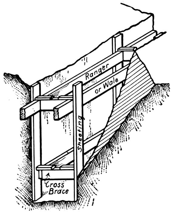
Fig. 104.—Skeleton Sheeting.
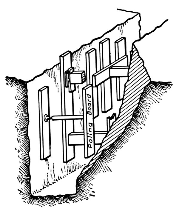
Fig. 105.—Poling Boards. Showing Different Types of Cross Bracing.
The method of placing poling boards is as follows: Excavate the trench as far as the cohesion of the bank will permit. Poling boards, 1½ inch to 2 inch planks, 6 inches or more in width, are then stood on end at the desired intervals along each side of the trench for the length of one ranger. The poling boards may be held in place by one or two rangers. Two are safer than one but may not always be necessary. If one ranger is to be used it is placed at the center of the poling board. After the poling boards are in position the rangers are laid in the trench and the cross 272braces are cut to fit. If wedges are to be used for tightening the cross braces, the cross braces are cut about 2 inches short. If jacks are to be used the braces are cut short enough to accommodate the jacks when closed, or adjustable trench braces may be used as shown in Fig. 106. The use of extension braces saves the labor of fitting wooden braces. With everything in readiness in the trench, the cross brace is pressed against the ranger which is thus held in place. The wedge or jack is then tightened holding the poling boards and cross brace in position.
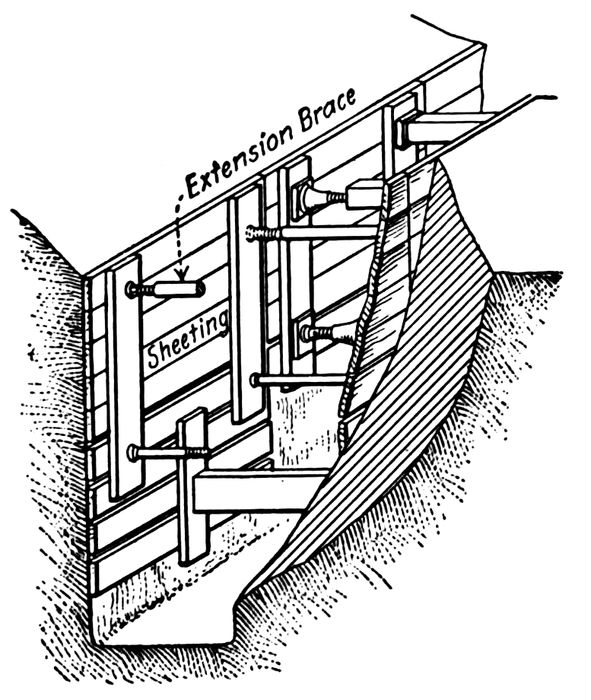
Fig. 106.—Box Sheeting. Showing Different Types of Cross Bracing.
153. Box Sheeting.—Box sheeting is composed of horizontal planks held in position against the sides of the trench by vertical pieces supported by braces extending across the trench. The arrangement of planks and braces for box sheeting is shown in Fig. 106. This type of sheeting is used in material not sufficiently cohesive to permit the use of poling boards, and under such conditions that it is inadvisable to use vertical sheeting which protrudes above the sides of the trench while being driven. This sheeting is put in position as the trench is excavated. No more of the excavation than the width of three or four planks need be unsupported at any one time. In placing the sheeting the trench is excavated for a depth of 12 to 24 inches. Three or four planks are then placed against the sides of the trench and are caught in position by a vertical brace which is in turn supported by a horizontal cross brace.
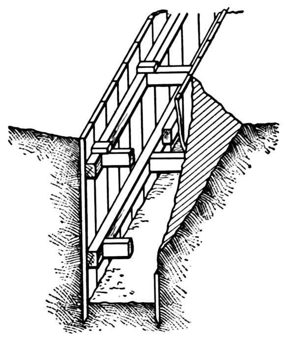
Fig. 107.—Vertical Sheeting.
154. Vertical Sheeting.—This is the most complete and the strongest of the methods for sheeting a trench. It consists of a system of rangers and cross braces so arranged as to support a solid wall of vertical planks against the sides of the trench. An arrangement of complete vertical sheeting is shown in Fig. 107. This type can be made nearly water-tight by the use of matched boards, Wakefield piling, steel piling, etc. Wakefield piling is made up of three planks of the same width and usually the same 273thickness. They are nailed together so that the two outside planks protrude beyond the inside one on one side, and the inside one protrudes beyond the two outside ones on the other side as shown in Fig. 108. The protruding inside plank forms a tongue which fits into the groove formed by the protruding outside planks of the adjacent pile.
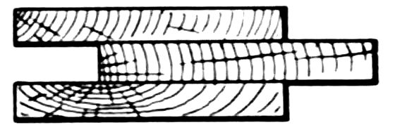
Fig. 108.—Wakefield Sheet Piling.
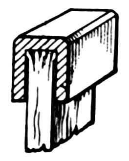
Fig. 109. Section through Malleable Steel Driving Cap.
In placing vertical sheeting the trench is excavated as far as it is safe below the surface. Blocks of the same thickness as the sheeting are then placed against the bank at the middle and at the ends of two rangers on opposite sides of the trench. The ranger rest against blocks, and are held away from the sides of the trench by them. Cross braces are next tightened into position opposite the blocks to hold the rangers in place. After the skeleton sheeting is in place the planks forming the vertical sheeting are put in position with a chisel edge cut on the lower end of the plank, with the flat side against the bank. The planks should be driven with a maul, the edge of the plank following closely behind the excavation. In relatively dry work the driving of the plank is facilitated by excavating beneath the edge as it is driven. The upper end of the sheeting should be protected by a malleable steel or iron cap to prevent brooming of the lumber. A cap is shown in Fig. 109. A sledge hammer may be used for driving when the lumber is protected. If the sheeting is to start at the surface and is to be driven by hand, the first length should not exceed 4 feet unless a platform is erected for the driver. Succeeding lengths may be longer, the driver standing on planks supported on the cross braces in the trench. Steam hammers and pile drivers are sometimes used for driving sheeting.
274The framework of the sheeting should be placed with a cross brace for each end of each ranger and a cross brace for the middle of each ranger. If the ends of two rangers rest on the same cross brace an accident displacing one ranger will be passed on to the next and might cause a progressive collapse of a length of trench, whereas the movement of an independently supported ranger should have no effect on another ranger. The cross braces should have horizontal cleats nailed on top of them as shown in Fig. 107 to prevent the braces from being knocked out of place by falling objects. In driving vertical sheeting a vacant place will be left behind each cross brace corresponding to the original block placed to hold the ranger away from the bank. This is an undesirable feature in the use of vertical sheeting. It is ordinarily remedied by slipping in planks the width of the slot and wedging or nailing them against the convenient cross bracing. In extremely wet trenches, after all other pieces of vertical sheeting are in place, the original cleat behind the cross brace can be knocked out and a piece of sheeting slipped into this opening and driven. Care must be taken in this event not to drive the rangers down when driving the sheeting. If the bracing begins to drop, it should be supported by vertical pieces between the rangers and resting on a sill at the bottom of the trench.
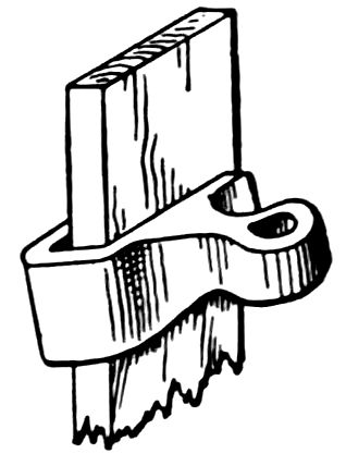
Fig. 110.—Steel Clamp for Pulling Wood Sheeting.
155. Pulling Wood Sheeting.—Wood sheeting is pulled after the completion of the trench by a device shown in Fig. 110. In wet trenches where the removal of the sheeting would permit a movement of the banks, resulting in danger to the sewer or other structures, the sheeting should be left in place in the trench. If sufficient saving can be made the sheeting is cut off in the trench immediately above the danger line, usually the ground water line. The cutting is done with an axe or by a power driven saw devised for the purpose.
156. Earth Pressures.[92]—The various theories of earth pressure are so conflicting in their conclusions as to be confusing. Rankine’s theory, the most frequently used, assumes that the pressure increases with the depth, whereas Meem’s theory[93] leads 275to an opposite conclusion. The discussion following Meem’s article is very illuminating. It indicates that no matter how good the theory, practical experience together with the use of generous sizes and close spacing are the best guides for bracing trenches and coffer dams. All are not possessed with the desired practical experience and some basis on which to commence work is essential. Another factor affecting computations of sizes based on theory is the tendency in practice to use the same size material for rangers and braces on any one job for all except very deep trenches and other special cases. Occasionally where there is an independent brace for each end of each ranger, the brace is made thinner, but is of the same depth as the ranger.
The application of Rankine’s theory of earth pressure to the computation of the sizes of rangers and braces will be shown. His formula for the active earth pressure against a retaining wall is:
P = wh cosθ cos θ − √cos2 θ − cos2 φ cos θ + √cos2 θ − cos2 φ
in which w =
the weight of earth in pounds per cubic foot;
h =
depth in feet at point at which pressure is to be determined;
θ =
the angle of surcharge, or the angle which the surface makes with the horizontal;
φ =
the angle of repose of the earth. Usually taken as 33°–41′ = 1½ horizontal to 1 vertical;
P =
the intensity of pressure in pounds per square foot on a vertical plane in a direction parallel to the surface of the ground.
In studying the pressures for trenches the surface of the ground will be assumed as horizontal and the formula reduces to
P = 1 − sin φ 1 + sin φwh.
157. Design of Sheeting and Bracing.—The trench shown in Fig. 111 is assumed to be constructed in moist sand weighing 110 pounds per cubic foot, with an angle of repose of 30 degrees. The material used for sheeting and bracing is yellow pine. The steps 276taken in the design of the sheeting and bracing for this trench are as follows:
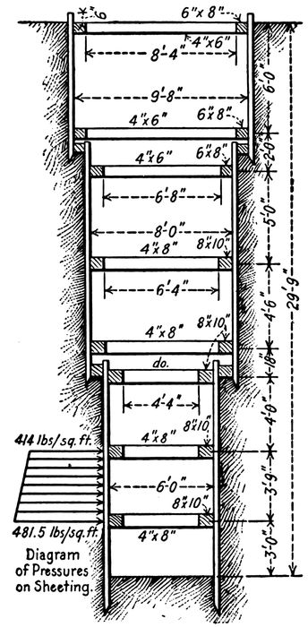
Fig. 111.—Diagram for the Design of Wood Sheeting.
1. Earth Pressure.—Substituting the units given in the data, in Rankine’s formula for earth pressures,
P = 36.7h.
Because the earth has been freshly cut and will not be kept open long enough to break up the cohesiveness of the banks it is customary to reduce the assumed pressure by dividing by 2, 3, or 4, according to the natural cohesiveness of the material. The cohesiveness of sand is not great, therefore the pressure will be assumed as one-half of the amount given by the formula, or
p = 18h.
2. Thickness of Sheeting and Spacing of Rangers.—It is desirable to use the same thickness of sheeting throughout the depth of the trench. Computations should therefore be commenced at the bottom of the trench where the pressures are the greatest and the thickest sheeting will be required. It is necessary to determine by trial a spacing for the rangers and a thickness of sheeting so that the sheeting is stressed to its full working strength. Having determined the thickness of the sheeting at the bottom, the remainder of the computations consists in determining the spacing of the rangers.
In the example the lower ranger will be assumed as 3 feet from the bottom of the trench and the distance to the next ranger as 4 feet.
277The intensity of pressure at 22 feet 9 inches is 409.5 pounds per square foot.
The intensity of pressure at 26 feet 9 inches is 481.5 pounds per square foot.
The distribution of pressures is shown by the diagram on Fig. 111. The maximum bending moment is slightly below the point midway between the rangers and for a 12–inch strip is 10,500 inch-pounds.
Assuming 3 inch sheeting the maximum fiber stress is:
f = Mc I = 10,400 × 1.5 × 12 12 × 27 = 568 pounds per square inch.
The working strength of yellow pine as given in Table 59, is 1200 pounds per square inch. Thinner sheeting should therefore be used.
TABLE 59
Working Unit Stresses for Timber
The most used value in the Building Codes of Baltimore, Boston, Cincinnati, Chicago, District of Columbia, and New York City
Wood Tension, lb. sq. in. Compression With Grain, lb. sq. in. Compression Across Grain, lb. sq. in. Transverse Bending, lb. sq. in. Shear With Grain, lb. sq. in. Shear Across Grain, lb. sq. in.
Yellow pine 1200 1000 600 1200 70 500
White pine 800 800 400 800 40 250
Spruce and Va. pine. 800 800 400 800 50 320
Oak 1000 900 800 1000 100 600
Hemlock 600 500 500 600 40 275
Chestnut 600 500 1000 800 150
Locust 1200 1000 1200 100 720
As published in American Civil Engineers Pocket Book.
Assuming 2–inch sheeting, the fiber stress is 1,300 pounds per square inch. This stress is too large. By reducing the ranger spacing slightly the stress can be brought within the required limits.
Assuming a ranger spacing of 3 feet 9 inches the depth to the upper ranger is changed to 23 feet and the maximum stress in the 2782–inch sheeting becomes 1,140 pounds per square inch, a satisfactory result. The results for the computations for the other ranger spacings are shown in Table 60. The spacing of the rangers at the sheeting junctions is controlled by convenience and is not computed so long as it is obviously safe.
3. Size of Rangers.—The rangers will be assumed as 16 feet long with two end cross braces and one intermediate cross brace for each ranger. Starting as before at the bottom of the trench.
The area of the panel below the ranger and between cross braces is 24 square feet.
The average intensity of pressure is 28.25 × 18 = 508.5 pounds per square inch.
The load transmitted to the ranger is 6,000 pounds.
Similarly the load transmitted to the ranger from the panel above is 6,890 pounds.
The total distributed load on the ranger is 12,890 pounds.
If b is the vertical dimension of the ranger and d is the horizontal dimension in inches, then from the beam theory, using f as 1,200 pounds per square inch, bd2 = M 200, in which M is expressed in inch-pounds. The maximum bending moment is
Wl 8 = 12,200 × 8 × 12 8 = 155,000 inch-pounds
Therefore, bd2 = 775.
An 8 × 10 inch beam will fulfill the conditions closely. Substituting these dimensions in the beam formula
f = Mc I = 155,000 × 5 × 12 8 × 1000
= 1,160 pounds per square inch tension in outer fiber. The results of the computations for other rangers are shown in Table 60.
4. Size of Cross Braces.—The cross braces act as columns. The dimensions of the cross braces are determined by trial in such a manner that the vertical dimension of the brace is equal to the vertical dimension of the ranger and the compressive stress in pounds per square inch is computed from the expression,
S ⪙ S1(1 − l 60d),[94]
279
TABLE 60
Computations for Sheeting and Bracing for Trench Shown in Fig. 111
Material is moist sand weighing 110 pounds per cubic foot, with an angle of repose of 30°. Lumber is yellow pine, with working stress as given in Table 59. Working stresses for columns given as S(1 − l 60d).
Sheeting 2 inches × 12 Inches Cross Braces
Depth Maximum Bending Moment, Inch-Pounds Maximum Fiber Stress, Pounds per Square Inch Depth and Description Total Load, Pounds Size, Inches Actual Intensity, Pounds per Square Inch Allowable Intensity, Pounds per Square Inch
23′–26.75′ 9100 1140 end at 26′ 9″ 6,445 4 × 8 202 784
19′–23′ 8800 1100 int. at 26′ 9″ 12,890 4 × 8 403 784
13′–17.5′ 8550 1070 end at 23′ 0″ 6,393 4 × 8 200 784
8′–13′ 7160 900 int. at 23′ 0″ 12,785 4 × 8 400 784
0′–6′ 3000 375 end at 19′ 0″ 3,930 4 × 8 123 784
int. at 19′ 0″ 7,860 4 × 8 240 784
end at 17′ 6″ 3,566 4 × 8 112 684
int. at 17′ 6″ 7,132 4 × 8 224 684
end at 13′ 0″ 4,385 4 × 8 137 684
int. at 13′ 0″ 8,770 4 × 8 274 684
end at 8′ 0″ 2,270 4 × 6 96 687
int. at 8′ 0″ 4,540 4 × 6 189 667
end at 6′ 0″ 1,344 4 × 6 60 584
int. at 6′ 0″ 2,687 4 × 6 112 584
end at 0′ 0″ 432 4 × 6 18 584
int. at 0′ 0″ 863 4 × 6 36 584
Rangers
Depth Area of Panel Below this Depth, Square Feet Intensity of Pressure, Pounds per Square Inch Total Load in Pounds Load Transmitted to the Ranger from the Size, Inches Maximum Bending Moment in Thousand Inch-Pounds Maximum Stress Pounds per Square Inch
Panel Below Panel Above Both Panels
26′ 9″ 24 508.5 12,200 6000 6890 12,890 8 × 10 155 1160
23′ 0″ 30 448 13,440 6545 6240 12,785 8 × 10 153 1150
19′ 0″ 32 378 12,100 5860 2000 7,860 8 × 10 94.3 708
17′ 6″ 12 328.5 3,942 1942 5190 7,132 8 × 10 85.6 636
13′ 0″ 36 274.5 9,880 4690 4080 8,770 8 × 10 105 790
8′ 0″ 40 189 7,560 3480 1060 4,540 6 × 8 54.4 850
6′ 0″ 16 126 2,020 960 1727 2,687 6 × 8 32.2 503
0′ 0″ 48 54 2,590 863 0 863 6 × 8 10.4 161
in which S =280
permissible crushing across the grain in a column whose length is greater than 15 diameters;
S1 =
unit working compressive strength of wood;
l =
length of the column;
d =
smallest dimension of the column;
l and d are in the same units.
The lower intermediate cross brace supports a length of 8 feet of the lower ranger on which the load has been found to be 12,890 pounds. The load on the end cross brace for the same ranger is one-half of this or 6,445 pounds. The length of each brace is 4 feet 4 inches. From Table 59, S1 is 1,000 pounds per square inch. From the column formula, S is 784 pounds per square inch.
A 4 × 8 inch cross brace is the smallest that is feasible. This is stressed only 12,890 pounds or 403 pounds per square inch, which is well within the permissible limits. The results of the other computations for cross braces are shown in Table 60.
158. Steel Sheet Piling.—This is coming into more general use with the increased cost of lumber and better acquaintance with its superiority over wood under many conditions. Although its first cost is higher than that of wood, the fact that with proper care it can be used almost an indefinite number of times renders it economical to contractors who may have an opportunity to make repeated use of it. The life of good yellow pine sheeting with the best of care may be as much as three or four seasons. With no particular care it will be destroyed at the first using. Fig. 112 shows various sections of steel piling used for trench sheeting. These forms are practically water-tight and aid materially in maintaining dry trenches. The piling can be made water tight by slipping a piece of soft wood between the steel sections when they are being driven, or by pouring in between the piles some dry material which will swell when wet. The piling is generally driven by a steam hammer and is pulled by attaching a ring through a bolt hole in the pile, or by grasping the pile with a clutch that tightens its grasp as the pull increases. An inverted steam hammer attached to the pile is sometimes used in pulling it. The impulses of the hammer together with a steady pull on the cable serve to drag out the most stubborn piece of piling.
281
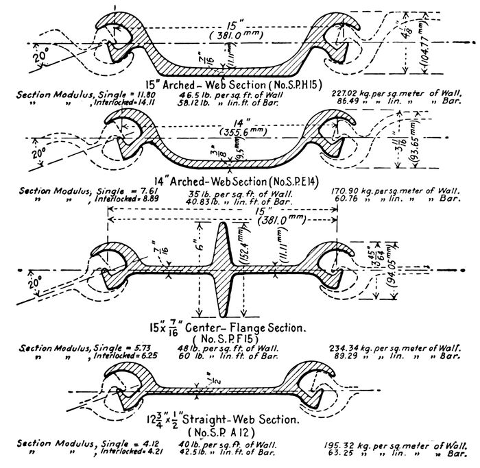
Fig. 112.—Sections of Lackawanna Steel Sheet Piling.
Line and Grade
159. Locating the Trench.—In order to locate a trench a line of stakes should be driven at about 50–foot intervals along the center line of the proposed sewer before excavation is commenced. Reference stakes or reference points to this line are located at some fixed offset or easily described point, or the stakes marking the center line of the trench may be driven at some constant offset distance one side of the trench, in order to avoid danger of loss or disturbance of the stakes. Grade or cut is seldom marked on the line of preliminary stakes, although the approximate cut may be indicated.
For hand excavation the foreman lays out the trench from these stakes. In machine work the operator guides the machine so as to follow the line of the stakes.
282160. Final Line and Grade.—After the excavation of the trench has proceeded to within a foot or two of the final depth, the grade and line are transferred to markers supported over the center of the trench. The markers are horizontal boards spanning the trench and held in position either by nails driven into stakes at the side of the trench, by nails driven into the sheeting, or by weights holding the boards on the ground. Two stakes driven in the ground at the side of the trench as shown in Fig. 113 are the common method of support. If the banks are too weak to stand under the jarring of the driving of the stakes, or pavement or other causes prevent their use the horizontal cross piece may be weighted down by bricks or a bank of earth. The cross pieces are located about every 25 feet along the trench and at any convenient distance above the surface of the ground. The nearer the ground the stronger the support but the greater the interference with work in the trench. The center line of the sewer is marked on the cross pieces after they are set, and vertical struts are nailed on them with one edge of the strut straight, vertical, and on the center line as shown in Fig. 1. The corresponding edge should be used on all struts in order to avoid confusion. The edge is placed in a vertical position by means of a plumb bob or carpenter’s level.
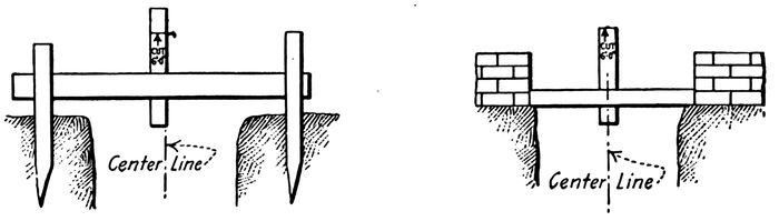
Fig. 113.—Methods for the Support of the Grade Line.
The cut to the invert of the sewer is recorded to an even number of feet where practicable by driving a nail in the upright strut so that the top edge of the nail is at the desired elevation above the sewer, or the upright is nailed with its top at the proper number of feet above the sewer invert. The cut is marked on the upright in feet, tenths, and hundredths from the recorded point to the elevation of the invert.
The inspector should watch these grade markers with care by sighting back along them to see that they are in line and have not 283moved. In quicksand or caving material the marks may move during the setting of the pipes and the levelman should be on the job constantly.