Chapter XI · CONSTRUCTION (continued 2)
Reading edition
When excavation is being done by machine the depth of the excavation is controlled by the operator who maintains a sighting rod on the machine in line with the grade marks on the uprights.
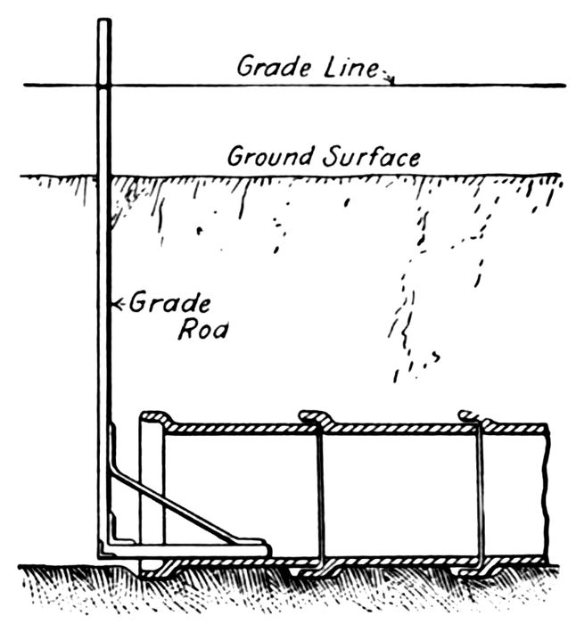
Fig. 114.—Diagram Showing the Use of the Grade Rod for Fixing the Elevation of a Sewer.
161. Transferring Grade and Line to the Pipe.—In transferring grade and line to the sewer a light strong string is stretched tightly from nail to nail on the uprights marking the line and grade. A rod with a right angle projection at the lower end, as shown in Fig. 114, is marked with chalk or a notch at such a distance from the end that when the mark is held on the grade cord the lower portion of the rod which projects into the pipe will rest on the invert. The pipe is placed in line by hanging a plumb bob so that the plumb bob string touches the grade and center line cord. These marks are taken only as frequently as may be necessary to keep the sewer in line. An experienced workman can maintain the line by eye for considerable distances. Measurements should never be taken to the top of the pipe in order to determine position and grade as the variations in the diameter of the pipe may cause appreciable errors.
The position and elevation of the forms for brick, concrete, and unit block sewers are located by reference to the grade line, or they may be placed under the immediate direction of the survey party, or by specially located stakes. For large sewers requiring deep and wide excavation the grade and line stakes are driven in the bottom of the trench about a foot above the finished grade. This requires the constant presence of an engineer who is usually available on work of such magnitude.
162. Line and Grade in Tunnel.—In tunnels, line and grade are given by nails driven in the roof, the progress of excavation or 284the shield being followed by eye and the forms set by direct measurement to the nails.
Tunneling
163. Depth.—The depth at which it becomes economical to tunnel depends mainly upon the character of the material to be excavated and on the surface conditions. In soft dry material with unobstructed working space at the surface, open cut may be desirable to depths as great as 35 or 40 feet. Tunnels are cut in rock at depths of 15 feet or less. In some very wet and running quicksand encountered in the construction of sewers for the Sanitary District of Chicago it was found economical to tunnel at depths of 20 feet and less. Crowded conditions on the surface, expensive pavements, or extensive underground structures near the surface may make it advantageous to tunnel at shallower depths than would otherwise be economical. Winter is the best season for tunneling as the workmen are protected from the elements and labor is more plentiful.
164. Shafts.—In sinking a shaft in soft material, the excavation is usually done by hand, the material being thrown into a bucket which is hoisted to the surface and dumped. The size of the shaft is independent of the size of the sewer and depends principally on the machinery which it is necessary to lower into the tunnel. Ordinarily a shaft 6 feet in the clear is satisfactory. A method of timbering a shaft is shown in Fig. 115. Because of the timbering the shaft must be started sufficiently large at the top to finish with the desired dimensions at the bottom. This excess size is sometimes obviated by driving the sheeting at an angle to maintain the same size of shaft from top to bottom.
In timbering a shaft as shown in Fig. 115 the upper frame is staked securely in position at the surface of the ground. This frame is composed of timbers fastened together in the form of a square with the ends of the timbers extending about 12 inches on all sides. The protruding ends are used to hold the frame in position. Excavation is begun inside the frame, and sheeting is driven around the outside of it as excavation progresses. Only two or three men can work advantageously at one time in these small shafts. The second frame is made up of the same size timbers, but all are cut off flush with the outside of the square. The 285outside dimensions of this frame are such as to allow sheeting to be slipped in between it and the sheeting already driven. The frame is lowered into position and supported from the upper frame by vertical struts nailed to it. The lower end of the sheeting already driven is held out from the lower frame by blocks of the thickness of the next length of sheeting. These blocks are removed as the next length of sheeting is placed and driven. The driving of the sheeting is facilitated by excavating beneath it as it descends.
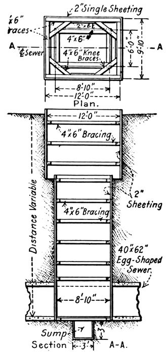
Fig. 115.—Section of Shaft Timbering. Abbot, Journal Western Society of Engineers, Vol. 22.
The sizes of sheeting and timbering should be computed on the same basis as that for trench sheeting except that for depths greater than 30 to 35 feet Rankine’s Theory is not applicable and judgment must be relied on for computing the sizes for deep shafts. In stiff dry material the pressures will change very little as the depth increases. Sheeting is needed in shaft excavation in rock only to protect the workmen from falling fragments, but in sand, particularly in quicksand and in wet ground, the pressures increase directly with the depth and the sheeting should be computed accordingly. Care must be taken to prevent the formation of cavities behind the sheeting, to fill them if formed, and to see that all pieces of the sheeting and bracing have a firm bearing. It is difficult to prevent the collapse of the shaft once the movement of earth against the sheeting has commenced.
Shafts are also sunk in soft ground by constructing a concrete or metal shell resting on a cutting shoe on the surface. The material inside is dug out and the shell sinks of its own or added weight. The first section of the shell may be from 5 to 10 feet long. As this section sinks other sections are added. This is called the caisson method. It is advantageous in wet ground and 286when the shafts are to be left as a permanent manhole. If a permanent shaft is to be left in an excavation being braced with wood, the permanent lining should follow within 20 to 30 feet of the shaft excavation. This is done to avoid the difficulty of maintaining a great length of temporary wood shaft with the danger of collapse, or of blocks or other objects falling on the workers below.
The distance between shafts is controlled by the depth and size of the tunnel, surface conditions, and the character of the material being tunneled. Except where surface conditions are crowded the shallower the cover to the tunnel the more frequent the shafts. The advantage of frequent shafts lies in the possibility of removing excavated material from the tunnel promptly, and in making ventilation of the tunnel easier. The saving made by the construction of numerous shafts must be balanced against the extra cost of the shafts. For the shallowest tunnels the shafts are seldom placed closer than every 500 feet.
165. Timbering.—After the shaft has been excavated to the proper grade the tunnel is struck out either by cutting through the wooden sheeting or by removing portions of the caisson lining. Practically all tunnels except those in solid rock must be framed to some extent. Some of the types of frames used in tunnel construction are shown in Fig. 116. Different combinations of these may be used in different classes of materials. In solid rock which remains firm on exposure no timbering is necessary. Where the roof only need be supported and the sides are strong enough to be used for support, a timber “hitch” or frame supported on the sides of the tunnel may be used. This is suitable for loose rock roofs with solid rock sides. Timbering such as is shown in the lower left hand corner of Fig. 116 becomes necessary in extremely soft, wet, or swelling material, where the bottom and sides as well as the roof tend to push in. The remaining frame in Fig. 116 shows a form frequently used and lying between the two extremes indicated. In wet tunnels a channel may be cut in the bottom below the sill for drainage purposes as shown in this form. The needle beam method of timbering is also shown in Fig. 116. This method of timbering is used mainly near the heading because of the speed and ease with which it can be installed, but it is undesirable because of the space occupied.
The distance between frames is dependent on the size of the 287tunnel and the character of the material. It is seldom greater than 6 feet and the frames are sometimes placed touching each other. The size of the timbering is a matter of experience and is generally determined by the judgment of the responsible person in charge of the construction as the result of observation during the progress of the work.
The sheeting between frames is called poling boards, or spiling or lagging according as it is sharpened and driven ahead of the excavation or placed after the excavation has progressed. The horizontal strips placed between the frames to keep them apart are called wales.
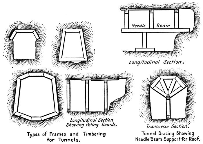
Fig. 116.—Types of Frames and Timbering for Tunnels.
In cutting out from the shaft in soft materials requiring support, where the width of the tunnel is the same or smaller than that of the shaft, a frame with a maximum width four thicknesses of sheeting less than the width of the tunnel is set up against the lining of the shaft. The vertical side pieces of the tunnel frame rest on the bottom frame of the shaft as a sill and are securely wedged into position. As the lining of the shaft at the top is cut away the top poling boards of the tunnel are slipped in between the cap of the first tunnel frame and the shaft frame immediately above 288it. The poling boards are driven with an upward pitch so that there may be room to slip the second length of boards between the next tunnel frame and the first length of boards. The placing of the side sheeting follows in a similar manner. Excavation is then started and the poling boards driven to keep pace with it. The next frame is placed in position and the previous sheeting or boards wedged out a sufficient distance to allow the advance lining to be slipped in when the wedges are removed. Waling pieces are nailed firmly between the frames to hold them in position. The various phases in the driving of a 12–foot sewer tunnel in Seattle are shown in Fig. 117.
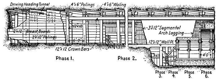
Fig. 117.—Stages of Sewer Tunneling. Eng. Record, Vol. 69, 1914, p. 195.
In soft or running material it may be necessary to protect the face of the tunnel by horizontal boards, called breast boards, wedged back to the last frame placed. The excavation is performed by removing one board at a time, excavating behind it and then replacing it in the advance position. The advance is made from the top downwards. This represents the method pursued in the most difficult material where wooden sheeting without a shield is used. The timbering during the advance may be modified in any manner that the character of the material will permit. The timbering may lag behind the excavation a distance of two or more frames, or it may be omitted altogether. Heavier timbering may be necessary in soft, slipping or shattered rock.
289
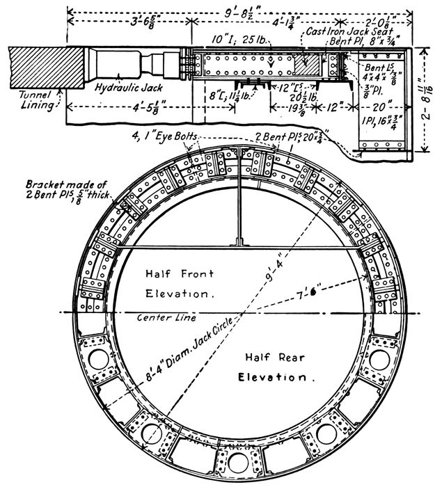
Fig. 118.—Shield for Driving Milwaukee Sewer Tunnel. Eng. News-Record, Vol. 80, 1918, p. 669.
166. Shields.—Shields are used in tunneling in soft wet material and are particularly suitable for work under air pressure. They are used in rock tunnels where water is anticipated or air pressure is used. The shields often save the expense and difficulty of timbering as the masonry of the sewer follows closely behind the shield. Fig. 118 shows the arrangement for a shield for tunneling in soft material in the construction of the Milwaukee sewers. The shield has an exterior diameter of 9 feet 4 inches and an overall length of 9 feet 8⅛ inches. The cutting edge section is 20 inches long. The shell is made of one inch plate to the back of the jack chambers and one-half inch plate in the tail. The shield is driven by ten 60–ton hydraulic jacks. The jacks 290are shown in position in the figure. These jacks rest against the finished tunnel lining and serve to consolidate it at the same time that they push the shield into the material to be excavated. The face of the tunnel is cut with a pick and shovel while the jacks are removed one at a time and a new ring of lining is put in place. The lining may be temporary timbering to receive the thrust of the jacks, but it is usually desirable that the permanent lining follow immediately behind the shield. Since the shield is larger than the outside of the lining the space left by its passage should be grouted immediately after it has passed.
167. Tunnel Machines.—Tunnel machines have been used successfully on sewer tunnels in soft materials, but not in rock.[95] The machines are of different types, but in general consist of a revolving cutting head, equipped with knives, and driven by an electric motor. The bearing on which the shaft for the cutting head rests is supported against the sides of the tunnel. The muck is carried away by means of a conveyor and dumped into muck cars without rehandling. Rapid progress can be made with these machines in suitable conditions.
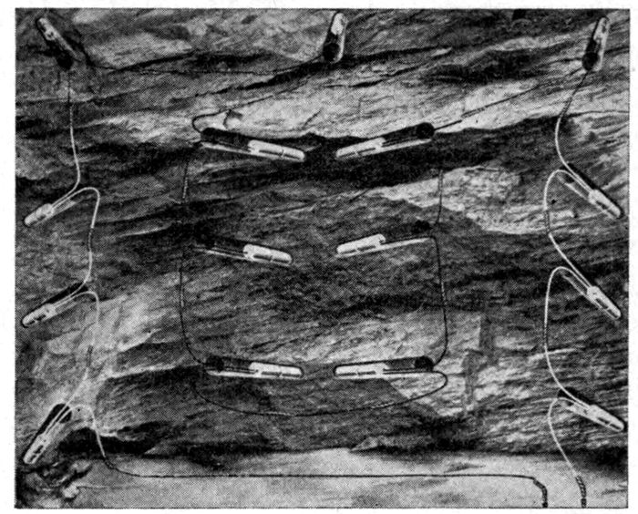
Fig. 119.—Method of Drilling and Loading Rock Tunnel Face. Courtesy, Aetna Power Co.
168. Rock Tunnels.—Tunnels in rock are advanced by drilling into the face as shown in diagrammatic form in Fig. 119. The 291holes near the center are driven in at an angle towards the center and to depths from 6 to 15 feet. The harder the rock the greater the angle with the tunnel. This is called the center cut. Other holes are driven near the outer edge of the tunnel and parallel to its axis. When fired, the wedge of rock between the center cut holes is thrown back into the tunnel and a delayed explosion then throws the sides into the hole thus made. A final delay thrusting shot throws the muck so formed away from the face of the tunnel. For tunnels up to 6 or 8 feet in height the entire bore is cut out in this fashion. For larger tunnels, the upper portion called the heading, is taken out in this way, and the remainder, called the bench, is taken out by drilling and blowing holes normal to the axis of the tunnel. The amount of powder necessary in the bench holes is much less than that required in the heading.
169. Ventilation.—No tunnel more than 50 feet long should be built without ventilation. A fair amount of air for ordinary conditions is 75 cubic feet of free air per minute per person in the tunnel, and double this amount for each animal. Where explosive gases are met, or under conditions where the tunnel is hot, five or six times as much air may be needed in order to cool the tunnel or to dilute the gases. In order that the air may be fresh and cool at the face of the tunnel where work is going on it should be conducted to the tunnel face in a pipe and blown out into the tunnel. Immediately following a blast at the face the current should be reversed so as to draw the poisonous gases out of the tunnel through the duct. The high pressure air line leading to the drills should be opened at the same time to create a current towards the face in order to accelerate the clearing of the air at the heading. The capacity of the air machines should be sufficient to exhaust four times the volume of the gases created by the explosion, in 15 minutes. This will ordinarily call for a capacity of about 4,000 cubic feet of free air per minute. If the same blower is to be used for exhausting the gases as for ventilation while work is going on, it should have a high overload capacity to care for this situation. The air line should be arranged to allow for reversal of flow.
The diameter of the air pipe should be determined by a study of the saving of the cost and operation of the air equipment compared to the increased cost of a larger pipe line. Other factors affecting the size of the pipe line to be used are: the available space in the tunnel, the temporary character of the installation, 292the use of the exhaust from high-pressure air machines for the purpose of ventilation, etc. Cast-iron, spiral-riveted galvanized sheet iron, and canvas pipes have been used for conducting low-pressure ventilating air.
Ventilation in tunnels working under air pressure is supplied from the compressors, and the air is delivered near the face of the heading, except that being used in the locks. In tunnels using air drills, the air for the drills is conducted through a separate pipe as it is not economical to compress the ventilating air to the pressure necessary to operate the drills.
170. Compressed Air.—Compressed air is used in tunnel work to prevent the entrance of water into the tunnel and to keep the work dry. The pressure of air used is closely that of the pressure of the ground water but in a large tunnel or a tunnel with a weak roof the pressure may be somewhat lower on account of the danger of blowing through the roof. It is evident that the water pressure cannot be balanced at the top and the bottom of the tunnel. To balance it at the bottom makes a blow out near the top more probable. To balance the pressure at the top may leave the bottom wet. Judgment and care must be exercised during construction and if the pressure is balanced at or near the bottom the roof must be carefully guarded by grouting and puddling with clay, or the surface, particularly if under water, may be covered with a clay bank. If the cavities in the tunnel lining are large, sawdust can be mixed with the grout to advantage, the mixture being pumped through holes in the roof by hand or power operated force pumps. “Blows” must be carefully guarded against as they endanger the lives of the workmen and threaten the loss of the tunnel. The pressure and volume of air supplied for some large subaqueous tunnels is shown in Table 61.
Labor under compressed air is arduous and dangerous with the best of safeguards.[96] Pressure more than about 43 pounds per square inch cannot be used and at this high pressure men cannot work more than four hours at a time. Little or no distress is noted at pressures less than 15 pounds.
293
TABLE 61
Volume and Pressure of Compressed Air in Tunnels
(American Civil Engineers Pocket Book)
Tunnel Maximum Distance High Water to Invert, Feet Minimum Cover in Feet Maximum Air Pressure, Pounds per Square Inch Average Air Pressure, Pounds per Square Inch Conditions and Cubic Feet of Free Air per Minute
City and South London 34 42 15 In water bearing-sand. 1660 cubic feet per minute per face. When grouted 1000 to 1300 cubic feet per minute per face
Blackwall 80 5 37 35 10,000 cubic feet per minute per face in open ballast for some time
Baker St. and Waterloo 70 18 35 28 In gravel, 3300 cubic feet of air per minute per face. Parallel tunnel 1650 cubic feet per min. per face
Greenwich 70 30 28 20 Average 83.5 per man per minute. Never less than 66.7
Battery, East River. N. Y. 94 12 42 26 In sand. Two working faces. Maximum 32,000
East River, N. Y., Penn. R.R. 93 8 42 27 Maximum for one face 25,000 cubic feet per minute for 24 hours. Capacity of plant for 8 faces, 80,400 cubic feet per minute
North River, N. Y., Penn. R.R. 98 20 37 26 Maximum in gravel 10,000 cubic feet per man per hour. Generally ranged between 1500 and 5000
Entrance and exit to the tunnel are gained through air locks. These are sheet iron cylinders concreted into the lining of the tunnel or shaft. Air-tight iron doors are provided at both ends, which open inwards towards the tunnel. On entering the lock from the outside the door to the tunnel is found tightly closed. The outside door is then closed by hand, the air valve is opened and air is admitted to the lock until the pressure on the lock side of the tunnel door equalizes that on the tunnel side and the tunnel door is swung open by hand. When the lock is open to the tunnel the pressure in the tunnel keeps the outside door closed. In order to leave the tunnel the process is reversed. Materials 294are passed through the lock by the lock tender or tenders who pass through the lock with the material if the pressure is low, or who manipulate the air outside of the lock if the pressure is high. If pressures of 30 to 40 pounds are being used, two or even three locks may be necessary.
Explosives and Blasting[97]
171. Requirements.—The desirable features in an explosive to be used in trenching and tunneling in rock are: (1) stability in make up so as not to deteriorate in strength or to become dangerous during storage, (2) imperviousness to ordinary variations in temperature and moisture, (3) insensibility to ordinary shocks received in transportation and handling, (4) not too difficult of detonation, (5) convenient form for transportation and loading and for making up charges of different weights, (6) the non-formation of poisonous gases when fired, (7) imperviousness to water and usefulness in wet holes, (8) power without bulk, etc.
172. Types of Explosives.—Explosives which fill some or all these requirements can be divided into two classes, deflagrating and detonating. A deflagration is an explosion transmitted progressively from grain to grain. A detonation is a sudden disruption caused by synchronous vibrations of a wave-like character. The deflagrating explosives are represented by gun-powders and contractors’ powders. They must be carefully tamped in the hole to develop their full power and they must be ignited by a fuse or flame. They are valueless in water or moist holes. These powders are used mainly for loosening frozen earth, soft sandstone, cemented gravels and similar materials where a thrusting action rather than a disruption is desired. The detonating explosives are most commonly represented by the dynamites. These are exploded by a shock usually caused by another explosive which has been ignited by a fuse or electric spark, and which is known as the “detonator.” Detonating explosives are more powerful than deflagrating explosives and are used in all but the softest materials.
295Gunpowder.—This is a mechanical mixture of sulphur, charcoal, and saltpeter generally in the proportions of 10 parts sulphur, 15 parts charcoal, and 75 parts saltpeter (sodium nitrate). It weighs about 62½ pounds per cubic foot and produces about 280 times its own volume in gas at a pressure of 4.68 tons per square inch at a temperature of 32 degrees F., which amounts to a pressure of approximately 38 tons per square inch at the temperature of explosion of 4,000 degrees F.
Blasting Powder.—This is a mixture of 19 parts sulphur, 15 parts charcoal, and 66 parts saltpeter. These powders are made in different size angular polished grains, from the size of a pin head to sizes just passing a ⅜ to ½ inch hole. The larger the grains the slower the action of the powder.
Nitro-Substitution Compounds.—These compounds are formed by the action of nitric acid on hydrocarbons. Triton, T.N.T., or trinitrotoluene, made famous during the war, is an example of these compounds. It is made by the successive nitration of toluene, a coal tar derivative. It melts at 80 degrees C., is very stable, and is of great explosive strength. It is manufactured in a convenient form, being compressed into blocks about 2 inches square by about 4 inches long with a specific gravity of about 1.5. The blocks are usually copper plated to protect the T.N.T. from moisture. The more dense it is the less its sensitiveness. It is also put up in crystalline form in cartridges like dynamite, in which condition it is practically equal to 40 per cent dynamite. It can be cut with a knife, pounded with a hammer, and will burn freely and slowly in small quantities in the open air without exploding. It is suitable for all but the hardest rocks. It creates poisonous gases on detonation which are quickly dissipated in the open air but which render it unsuitable for use in tunnel work.
Nitro-glycerine.—This is formed by the action of nitric and sulphuric acids on animal compounds such as gelatine or glycerine. Nitro-glycerine is a yellowish, oily, highly unstable explosive liquid with a specific gravity of about 1.6. It will burn quietly when ignited in the open air. It will freeze at 41 degrees F., and will explode at 388 degrees F., or on concussion at a lower temperature. It develops about 1,500 times its volume in gas, which due to the heat of combustion is increased to about 10,000 times its volume. It is a very dangerous explosive to handle, and is unsuitable for use in the liquid form.
296Blasting Gelatine.—This is made by soaking guncotton in nitro-glycerine. Gelatine dynamite is a combination of blasting gelatine and an absorbent. Forcite is a gelatine dynamite in which the blasting gelatine, forming 50 per cent of the compound, contains 90 per cent nitro-glycerine and 2 per cent guncotton; and the absorbent, forming the other 50 per cent of the compound, contains 76 per cent of sodium nitrate, 3 per cent sulphur, 20 per cent of wood tar, and 1 per cent of wood pulp.
Blasting gelatine is packed in a jelly-like mass in metal lined wooden boxes. It is less sensitive than straight dynamite and is one of the most powerful explosives known. It can be made up to equal 100 per cent dynamite. It is suitable for use in the hardest rocks and for subaqueous work as it is not affected by moisture. It is suitable for use in tunnels as the amount of carbon monoxide, peroxide of nitrogen, hydrogen sulphide and other dangerous gases is comparatively low when fully detonated. Gelatine dynamite[98] is sold as 30 per cent to 70 per cent dynamite, the actual percentage of nitro-glycerine being less than the nominal quantity given.
Dynamite.—The dynamites are made by soaking nitro-glycerine in some absorbent. If the absorbent is some neutral substance such as infusorial earth the combination is known as a true dynamite. The false or active dynamites are those in which the absorbent is also an explosive compound. The false dynamites form the best known contractors’ explosives. Among the materials mixed with the nitro-glycerine are: magnesium carbonate, sulphur, wood meal, wood pulp, wood fiber, wood tar, nut galls, kieselguhr, sawdust, resin, pitch, sugar, charcoal, and guncotton. The strength of dynamites is noted by the per cent of nitro-glycerine and nitro substitutes contained. Dualin and Hercules powder both contain 40 per cent nitro-glycerine. Dualin contains 30 per cent sawdust and 30 per cent potassium nitrate, but the Hercules powder, which is stronger, contains 16 per cent sugar, 3 per cent potassium chlorate, 31 per cent potassium nitrate, and 10 per cent magnesium carbonate.
Dynamite is the most common explosive used on construction work. It is supplied in cylindrical sticks wrapped in paper, the diameter of the sticks varying between ⅞ and 2 inches. They are about 8 inches long. Forty per cent dynamite is the common 297strength found on the market. It is suitable for ordinary work in all but very hard rocks or very soft material. Direct contact with water separates the nitro-glycerine from the base and is dangerous when the explosive is used in wet places unless it is fired immediately after the hole is loaded. It freezes at about 42 degrees F., or at even higher temperatures and in the frozen state it is highly dangerous, requiring powerful detonators for firing, but exploding spontaneously from a slight jar, or the breaking of the stick. Special low-freezing dynamites are made that will not freeze above 35 degrees F.
Ammonia Compounds.—Ammonia dynamite is a combination of nitro-glycerine, ammonium nitrate and such other ingredients as sodium nitrate, calcium carbonate and combustible material. This form of explosive is advantageous for underground work because, like gelatine dynamite, its explosion does not create large quantities of poisonous gases. It has a low freezing point and is relatively low in cost. It is seriously affected by moisture, however, and can not be used in wet places. Ammonium nitrate explosives which do not contain nitro-glycerine include 70 per cent to 95 per cent ammonium nitrate and some combustible material. Ammonal is a special type of this class formed by a mixture of ammonium nitrate, aluminum, and triton. All of these explosives are deliquescent, insensitive to shock, and are cheaper than the dynamites.
173. Permissible Explosives.—As specified by the United States Bureau of Mines explosives whose rapidity, detonation, and temperature of explosion will not ignite explosive mixtures of pit gases and air are known as permissible explosives. They include nitrate explosives, ammonia dynamite, and others.
Gunpowder, triton, picric acid, blasting gelatine, dynamite, guncotton, etc., are not classed as permissible explosives.
174. Strength.—The relative weights for equal strength of various explosives are given in Table 62.
298
TABLE 62
Relative Weights of Explosives with the Same Strength as a Unit Weight of 40 Per Cent Dynamite
Explosive Relative Weight
Picric acid 0.86
Gun powder (well tamped) 3.10
Straight dynamite, 15% 1.45
Straight dynamite, 20 1.33
Straight dynamite, 25 1.28
Straight dynamite, 30 1.18
Straight dynamite, 35 1.07
Straight dynamite, 40 1.00
Straight dynamite, 45 0.93
Straight dynamite, 50 0.86
Straight dynamite, 55 0.83
Straight dynamite, 60 0.78
Low-freezing dynamites are the same as straight dynamites
Smokeless powder, well tamped 0.74
Triton 0.86
Blasting gelatine 0.43
Gelatine dynamite, 30% 1.28
Gelatine dynamite, 35 1.21
Gelatine dynamite, 40 1.14
Gelatine dynamite, 50 1.04
Gelatine dynamite, 55 0.97
Gelatine dynamite, 60 0.90
Gelatine dynamite, 70 0.83
Ammonia dynamites are the same as gelatine dynamites.
Chlorates (sprengle) Rack-a-rock 1.33
Guncotton 0.72
175. Fuses and Detonators.—The explosion of gunpowder and other deflagrating explosives is caused by the direct application of a flame led to the charge by a powder fuse, or they may be fired by a blasting cap which is itself exploded by the heat from a fuse or an electric spark. The powder fuse is a cord made up of a train of powder securely wrapped in a number of thicknesses of woven cotton or linen threads and usually made waterproof. Ordinary fuse burns at about 2 feet per minute but there may be wide variations from this rate due to the quality of the fuse, moisture, temperature, or pressure. Moisture tends to retard the rate, pressure to increase it. Instantaneous fuse will burn at about 120 feet per second. It is distinguished from the ordinary safety fuse both by eye and touch due to the rough red braid with which it is covered. It is used in firing a number of charges simultaneously. Powder fuses are lighted by the application of a flame or smoldering torch to the freshly cut or opened end exposing the powder grains. Cordeau Bickford is lead tubing filled with triton, in which the flame travels at about 17,000 feet per second. This is also used for igniting charges simultaneously.
The detonation of an explosive is caused by the shock or heat of the explosion of a more sensitive substance which has been exploded by a powder fuse or electric spark. The common method of detonating explosive charges is by the firing of a blasting 299cap. These caps are copper cylinders, closed at one end, about 1½ inches long and ¼ to ⅜ of an inch in diameter, or larger. They contain a mixture of about 85 per cent fulminate of mercury and 15 per cent potassium chlorate held in place by a wad of shellac, collodion, or paper. The strength of detonators is based on the weight of fulminate of mercury and is designated as shown in Table 63.
TABLE 63
Strength of Blasting Caps
Blasting Cap, Commercial Grade Grains Fulminate of Mercury
3X or Triple 8.3
4X or Quadruple 10.0
5X or Quintuple 12.3
6X or Sextuple 15.4
7X or Number 20 23.1
8X or Number 30 30.9
Single strength 12.3
Double strength 15.4
Triple strength 23.1
Quadruple strength 30.9
The force of the explosion is markedly affected by the strength of the caps, the effect being greater for low-grade powders. For 40 per cent dynamite the explosion caused by a 5X cap is 15 per cent stronger than that caused by a 3X cap. For 60 per cent dynamite the difference is only 6 per cent. The deterioration of the caps will reduce the strength of an explosion noticeably. With straight dynamite, 3X caps are generally used, but with gelatine dynamite 6X or heavier caps must be used. Caps may be tested by exploding them in a confined space and noting the report and the effect on the shell. A full strength cap will tear the shell into minute pieces, while a deteriorated cap will merely tear it into three or four large pieces. An ordinary blasting cap is shown in Fig. 120 together with other equipment for blasting.
Firing by electricity is generally safer and more satisfactory than by the use of ordinary caps and powder fuses. The explosion is more certain and its exact time is under the control of the operator. Fig. 121 shows a section through an electric blasting cap or 300detonator, commonly called an electric fuse. Delayed action electric detonators are made by inserting a slow-burning substance between the platinum bridge and the detonating substance. The time of delay is controlled by the depth of the slow-burning substance. Delayed action detonators are useful in tunnel work where it is desired to explode the charge in three or four stages in order that the debris from one charge may be out of the way of the following, and that the forces of the explosions may not serve to nullify each other.
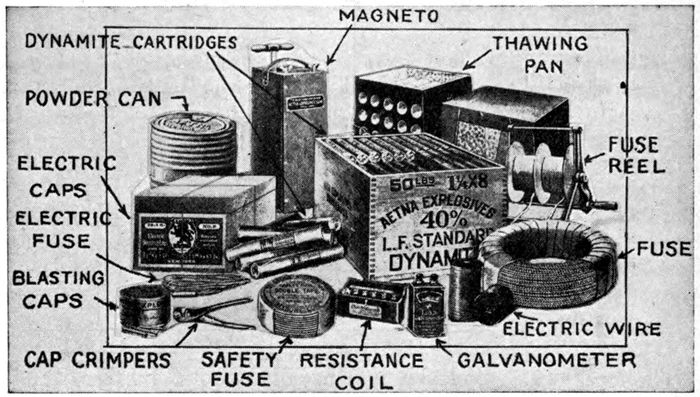
Fig. 120.—Blasting Supplies. Courtesy, Aetna Powder Co.
176. Care in Handling.—Some of the don’ts in the handling of explosives recommended by the U. S. Army Engineer Field Manual are: in the use of nitro-glycerine explosives of all kinds—
(a) Don’t store detonators with explosives. Detonators should be kept by themselves.
(b) Don’t open packages of explosives in a store house.
(c) Don’t open packages of explosives with a nail puller, pick or chisel. Packages should be opened with a hard wood wedge and mallet, outside of the magazine and at some distance from it.
(d) Don’t store explosives in a hot or damp place. All explosives spoil rapidly if so stored.
(e) Don’t store explosives containing nitro-glycerine so that the cartridges stand on end. The nitro-glycerine is more likely to leak from the cartridges when they stand on end than it is when they lie on their sides.
301(f) Don’t use explosives that are frozen or partly frozen. The charge may not explode completely and serious accidents may result. If the explosion is not complete the full strength of the charge is not exerted and larger quantities of harmful gases are given off.
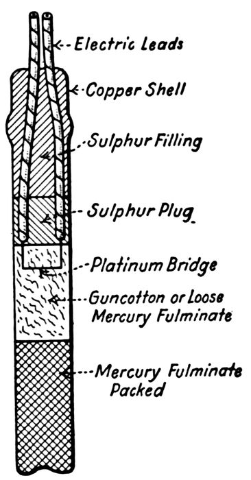
Fig. 121.—Electric Fuse. Full size.
(g) Don’t thaw frozen explosives in front of an open fire, nor in a stove, nor over a lamp, nor near a boiler, nor near steam pipes, nor by placing cartridges in hot water. Use a commercial or improvised thawer.
(h) Don’t put hot water or steam pipes in a magazine for thawing purposes.
(i) Don’t carry detonators and explosives in the same package. Detonators are extremely sensitive to heat, friction, or blows of any kind.
(j) Don’t handle detonators or explosives near an open flame.
(k) Don’t expose detonators or explosives to direct sunlight for any length of time. Such exposure may increase the danger in their use.
(l) Don’t open a package of explosives until ready to use the explosive, then use it promptly.
(m) Don’t handle explosives carelessly. They are all sensitive to blows, friction, and fire.
(n) Don’t crimp a detonator (blasting cap) around a fuse with the teeth. Use a cap crimper, which is supplied for this purpose.
(o) Don’t economize by using a short length of fuse.
(p) Don’t return to a charge for at least one-half hour after a miss fire. Hang fires are likely to happen.
(q) Don’t attempt to draw nor to dig out the charge in case of a miss fire.
Some of the positive rules in connection with the handling of explosives are: build the magazine on an earth foundation remote from any other structures, protect it with earth embankments that will direct the force of the explosion upwards, and build it of materials that will supply as few missiles as possible. Hollow tile brick, double-walled galvanized iron filled with sand, and similar constructions are satisfactory. The magazine may be 302heated by steam or hot-water pipes so located that explosives cannot come in contact with them, or by a cluster of incandescent bulbs, but if the explosives become frozen they must not be thawed out by turning on the steam or hot water. If powder or nitro-glycerine is dropped on the floor the magazine should be emptied, washed out with a hose and spots of nitro-glycerine scrubbed with a brush and a mixture of ½ gallon of wood alcohol, ½ gallon of water and 2 pounds of sodium sulphide. Frozen explosives may be thawed by spreading out on special shelves in a warm thaw house—not in the magazine proper, by burying in a manure pile so that the explosive may not become moistened, or more commonly by heating slowly in a water bath. This is a dry kettle in which the explosives are placed and covered. The kettle is then put in another containing water which is heated gently to about 120 degrees F. It should not be boiled.
In case of a miss fire, instead of digging out the old charge put a new charge on top of the old and fire the two simultaneously.
177. Priming, Loading, and Firing.—Priming is the act of placing the cap or detonator in the cartridge of explosive. The primer is either the cap or the cap and cartridge which are to be detonated by the fuse. If a cap and safety fuse are to be used the paper at the upper end of the cartridge is opened, a hole is poked in the explosive with the finger or a piece of wood, the cap and the attached fuse are pushed into the hole and gently embedded in the explosive so that the end of the cap is exposed sufficiently to prevent the fuse from igniting the dynamite directly. The paper is then folded up and tied firmly around the fuse with a piece of string. The result is shown in Fig. 122.
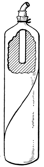
Fig. 122.—Dynamite Cartridge, Safety Fuse, and Cap.
In placing the fuse in the cap the end of the fuse is cut off square, and inserted in the open end of the cap, care being taken not to spill the loose grains of powder or to grind the fuse down on top of the cap. When the fuse is shoved firmly into place the upper portion of the copper cap is pressed or crimped with the cap crimpers shown in Fig. 120.
The number of primers to be used is dependent on the size 303and location of the charge, but in practically all sewer work only one primer is used to each hole. In bulky charges the primer should be placed near the center of the charge and the fuse so protected that it will not ignite the charge prematurely. In drill holes the primer is put in last with the cap end down.
In loading a hole, it is first pumped and cleaned out. This can be done satisfactorily with the end of a stick frayed out into a broom. Cartridges which very nearly fill the hole are dropped in one at a time and are pressed firmly together, with a light wooden tamping bar. They should not be pounded. After the primer is placed, a wad of clay or similar material is pressed gently into the hole against it and the hole is then filled with well-tamped clay. In tunnel work tamping is not so essential as an overcharge of powder is usually used and the time of tamping, which is worth more than two or three sticks of dynamite, is saved. In handling bulk explosives, such as gunpowder, they are poured into the hole, the fuse is set in the upper portion and the remainder of the hole is tamped with clay as for dynamite cartridges.
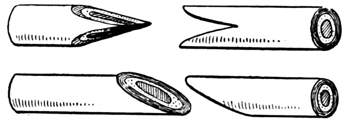
Fig. 123.—Methods for Cutting Safety Fuse for Splicing.
If a large number of charges are to be fired simultaneously with a safety fuse, the length of the fuse to each charge should be made equal or a safety fuse used to a common center and approximately equal lengths of instantaneous fuse or Cordeau Bickford used from there to the charge. In splicing the fuses for such connections they are cut diagonally as shown in Fig. 123 and bound together firmly with tape. Electric connections are particularly advantageous under such conditions as they avoid the dangers incidental to spliced fuses and are less expensive. In tunnel work simultaneous electric detonation is not desirable as the holes should be fired progressively: 1st, the cuts; 2nd, the relievers; 3rd, the backs; 4th, the sides; and 5th, the lifters. Different lengths of safety fuse, or delayed action electric fuses can be used for these delay shots.
In igniting a safety fuse an open flame such as that furnished by a match or candle is the most satisfactory. For electric fuses 304the current is generated by a magneto shown in Fig. 120. Pressing vigorously down on the handle closes the circuit and generates an electric current which heats the platinum bridges and explodes the charges. For the small number of charges used in ordinary construction they are connected in series so that if there is a broken connection anywhere no charge will be exploded. If many charges are to be fired and a line circuit is to be used, the final connection should not be made until just before the charge is to be fired in order to obviate the danger of stray currents firing the charge prematurely. Care should be taken to see that all connections are good and that there are no broken wires on the line.
178. Quantity of Explosive.—The quantity of explosive to be used can be determined satisfactorily only by experience on the job in question, as the factors affecting the necessary quantity are so diverse. The figures in Table 64 indicate the relative amounts needed under different conditions.
TABLE 64
Quantities of Explosives
Kind of Rock Drift in Feet Feet[99] of Hole Black[99] Powder, Pounds Dynamite[99], Pounds Grade of Dynamite, Per Cent Remarks
Limestone, Chicago Drainage Canal 12 0.40 0.75 40 Gillette
Limestone for crushing 6 1.00 0.70 40 Gillette
Limestone for cement 20 0.37 50 Gillette
Limestone, holes sprung 15 0.40 0.26 50 Gillette
Sandstone, side cut 20 0.10 1.0 0.10 40 Gillette
Sandstone, thorough cut 20 0.20 2.0 0.20 40 Gillette
Shale, soft side cut 24 0.08 0.7 0.03 40 Gillette. Open cut
Shale, hard thorough cut 24 0.20 1.5 0.10 40 Gillette
Granite for rubble 16 1.36 0.20 60 Gillette
Gneiss, New York City 12 1.33 0.60 40 Gillette
Gneiss, New York City 14 0.63 0.50 40 Gillette
Syenite, Treadwell Mine 12 1.70 0.67 40 Gillette
Magnetic iron ore 12½ 0.32 0.44 52 Gillette
Trap, seamy 14 0.35 0.20 75 Gillette
Trap, massive 17 1.00 0.70 40 Gillette
Granite, Grand Trunk 25 0.10 0.80 50 50% dynamite used to spring holes
Clay, rock and Gypsum Tunnel 1.00
Hard shale Tunnel 2.07 Grade varied ⅗ at 45%, ⅕ at 60%, some at 100%
Hard rocky slate Tunnel 1.60 3.57
Hard rocky slate Tunnel 1.46 3.57
Mill Creek sewer, St. Louis Tunnel 4.00 60 Mun. Eng’g. Vol. 52, p. 14
Pipe Sewers
179. The Trench Bottom.—It is customary to dig the bottom of the trench to conform to the shape of the lower 45 degrees to 90 degrees of the sewer if the character of the material will allow such construction. In soft material which will not hold its shape the sewer may be encased in concrete or a concrete cradle may be prepared for the pipe. In rock the trench is excavated to about 6 inches below grade and refilled with well-tamped earth so as to form a cradle giving bearing to 60 to 90 degrees of the pipe circumference. For large sewers to be constructed in the trench special foundations are sometimes built.
180. Laying Pipe.—Before the pipe is lowered into the trench the sections which are to be adjacent should be fitted together on the surface and the relative positions marked by chalk so that the same position can be obtained in the trench.
Small pipes are lowered into the trench and swung into position on a hook as shown in Fig. 124. Pipes up to 15 or 18 inches in diameter can be handled by the pipe layer and helper in the trench without assistance. Heavier pipes may be lowered into the trench by passing ropes around each end of the pipe. One end of the rope is fastened at the surface and the ropes are paid out by the men at the surface as the pipe is lowered. If the pipes have been fitted together and marked at the surface it is undesirable to use this method of lowering as the position in which the pipes arrive in the bottom of the trench can not be easily predicted. A cradle may be used for shoving the pipe into position as is shown in Fig. 125.
306
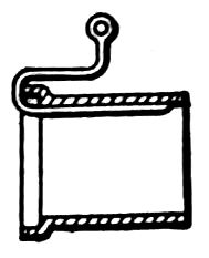
Fig. 124.—Hook for Lowering and Placing Sewer Pipe.
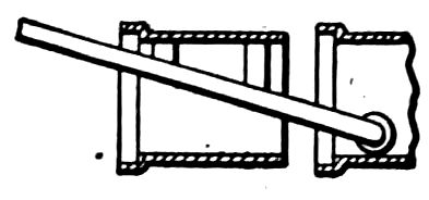
Fig. 125.—Cradle for Placing Sewer Pipe.
Pipes above 24 to 27 inches in diameter are too large to be handled from the side of the trench. A hook as shown in Fig. 124 is placed in the pipe so that it will be in the proper position when lowered. It is raised by a rope passing through a block at the peak of a stiff-legged derrick which spans the trench, or by a crane. If a derrick is used the rope passes to a windlass on the opposite side of the trench from the pipe. Mechanical power may be used for raising pipes too heavy to be raised by hand. The pipe is then lowered and swung into position while supported from the derrick. Excessive swinging is prevented by holding back on the guide rope as the pipe is raised and lowered.
Pipes are usually laid with the bell end up grade as it is easier to fit the succeeding pipe into the bell so laid and to make the joint, particularly on steep grades. The Baltimore specifications state:
The ends of the pipe shall abut against each other in such a manner that there shall be no shoulder or unevenness of any kind along the inside of the bottom half of the sewer or drain. Special care should be taken that the pipe are well bedded on a solid foundation.... The trenches where pipe laying is in progress shall be kept dry, and no pipe shall be laid in water or upon a wet bed unless especially allowed in writing by the Engineer. As the pipe are laid throughout the work they must be thoroughly cleaned and protected from dirt and water, no water being allowed to flow in them in any case during the construction except such as may be permitted in writing by the Engineer. No length of pipe shall be laid until the preceding length has been thoroughly embedded and secured in place, so as to prevent any movement or disturbance of the finished joint.
307The mouth of the pipe shall be provided with a board or stopper, carefully fitted to the pipe, to prevent all earth and any other substances from washing in.
181. Joints.—Pipes may be laid with open joints, mortar joints, cement joints, or poured joints. Open joints are used for storm sewers in dry ground close to the surface. Mortar and cement joints are commonly used on all sewers except in special cases. Cement joints are more carefully made than mortar joints and result in a greater percentage of water-tight joints. Poured joints are used in wet trenches where it is necessary to exclude ground water from the sewer.
A specification used in some cities for open joints is:
Pipes laid with open joints are to be laid with their inverts in the same straight line and shall be firmly bedded throughout their length on the bottom of the trench. No cement or mortar is to be used in the joints. Not more than ⅛ inch shall be left between the spigot end of the pipe and the shoulder of the hub of the pipe into which it fits. The joints shall be surrounded with cheese cloth, burlap, broken pipe, gravel or broken stone.
The purpose of the cheese cloth, etc., is to prevent fine earth from sifting into the pipe until the cheese cloth or other material has rotted away, by which time the earth has become arched over the opening.
Mortar joints are specified by Metcalf and Eddy as follows:
Before a pipe is laid the lower part of the bell of the preceding pipe shall be plastered on the inside with stiff mortar of equal parts of Portland cement and sand, of sufficient thickness to bring the inner bottoms of the abutting pipe flush and even. After the pipe is laid the remainder of the bell shall be thoroughly filled with similar mortar and the joint wiped inside and finished to a smooth bevel outside.
In some work a wood block or a stone is embedded in the mortar at the bottom of the joint to bring the spigot in place concentric with the next pipe.
Cement joints are specified in the Baltimore specifications as follows:
Cement joints shall be made with a narrow gasket of hemp or jute and cement mortar, and special care shall be taken to secure tight joints. The gasket shall be soaked 308in Portland cement grout and then carefully inserted between the bell and the spigot, and well calked with suitable hardwood or iron calking tools. It shall be in one continuous piece for each joint, and of such thickness as to bring the inverts of the two pipes smooth and even. The remainder of the joint shall be filled with cement mortar all around, on the bottom, top and sides, applied by hand with rubber mittens, well pressed into the annular space and beveled off from the outer edge of the bell to a distance of two inches therefrom, or to an angle of 45 degrees. The inside of each joint shall be thoroughly cleansed of all surplus mortar that may squeeze out in making the joint; and to accomplish this some suitable scraper or follower, or form shall be provided and always used immediately after each joint is finished.
Cement joints so made, form the most satisfactory joint for ordinary conditions and are the most frequently used. They are not always water-tight and can be penetrated by roots. Some roots are able to penetrate holes of almost microscopic size and to form growths in the sewer or to split the joints.
Poured joints are made by pouring some jointing compound, while in a fluid state, into the joint in which it hardens, thus sealing the joint. Water-tightness in sewer lines to exclude ground water has also been attempted by using the ordinary cement joint and surrounding the pipe with a layer of cement or concrete. This has not always been successful as it is difficult to obtain the proper class of workmanship in wet sewer trenches.
The requisite qualities of a poured jointing material are:
(1) It should make a joint proof against the entrance of water and roots.
(2) It should be inexpensive.
(3) It should have a long life.
(4) It should not deteriorate in sewage which may be either acid or alkaline.
(5) It should adhere to the surface of the pipe.
(6) It should run at a temperature below about 400° F., as too high temperatures will crack the pipe.
(7) It should neither melt nor soften at temperatures below 250° F. in order to maintain the joint if hot liquids are poured into the sewer.
(8) It should be elastic enough to permit slight movements of the pipes.
(9) It should not require great skill in using as it must be handled ordinarily by unskilled workers.
309The materials used for poured joints are: cement grout; sulphur and sand; and asphalt or some bituminous compound made of vulcanized linseed oil, clay, and other substances the resulting mixture having the appearance of vulcanized rubber or coal tar. The bituminous materials most nearly approach the ideal conditions.
Cement grout is made up of pure cement and water mixed into a soupy consistency. Its main advantages are its cheapness and ease in handling in wet trenches or difficult situations. The result is no better than a well made cement joint. There is no elasticity to the joint and a movement of the pipe will break it.
Sulphur and sand are inexpensive, comparatively easy to handle, and make an absolutely water-tight and rigid joint which is stronger than the pipe itself. It frequently results in the cracking of the pipe and is objected to by some engineers on that account. In making the mixture, powdered sulphur and very fine sand are mixed in equal proportions. It is essential that the sand be fine so that it will mix well with the sulphur and not precipitate out when the sulphur is melted. Ninety per cent of the sand should pass a No. 100 sieve and 50 per cent should pass a No. 200 sieve. The mixture melts at about 260° F. and does not soften at lower temperatures. For making a joint in an 8 inch pipe about 1½ pounds of sulphur, 1½ pounds of sand, ½ pound of jute, and 0.4 pound of pitch are used. The pitch is used to paint the surface of the joint while still hot in order to close up any possible cracks.
Among the better known of the bituminous joint compounds are: “G.K.” Compound made by the Atlas Company, Mertztown, Pa., Jointite and Filtite, manufactured by the Pacific Flush Tank Co., Chicago and New York, and some of the products of the Warren Brothers Co., Boston. These compounds fill nearly all of the ideal conditions except as to cost and ease in handling. They are somewhat expensive and if overheated or heated too long become carbonized and brittle. In cold weather they do not stick to the pipe well unless the pipe is heated before the joint is poured. On some work joints have been poured under water with these compounds, but success is doubtful without skillful handling. An overheated compound will make steam in the joint causing explosions which will blow the joint clean, 310and an underheated compound will harden before the joint is completed.
The materials should be heated in an iron kettle over a gasoline furnace or other controllable fire, until they just commence to bubble and are of the consistency of a thin sirup. Only a sufficient quantity of material for immediate use should be prepared and it should be used within 10 to 15 minutes after it has become properly heated. The ladle used should be large enough to pour the entire joint without refilling. There are other important points to be considered in pouring joints which can be learned best by experience.
The quantity of material necessary for making these joints, as announced by the manufacturers, is shown in Table 65.
TABLE 65
Quantity of Compound Needed for Poured Joints
Diameter of Pipe, in Inches Quantity of Material in Pounds per Joint
Standard Socket Deep and Wide Socket
Jointite Filtite G. K. Jointite Filtite G. K.
6 0.82 0.72 0.42 1.46 1.28 0.72
8 1.06 0.95 0.73 1.82 1.60 1.25
10 1.30 1.15 0.89 2.26 1.98 1.52
12 2.08 1.82 1.42 2.65 2.32 1.80
15 2.52 2.20 1.74 3.20 2.80 2.20
18 3.02 2.64 2.58 3.75 3.29 3.25
20 3.44 3.00 2.86 4.30 3.78 3 60
22 3.62 3.16 3.13 4.62 4.07 3.97
24 4.03 3.50 3.41 4.91 4.31 4.27
In making a poured joint the pipes are first lined up in position. A hemp or oakum gasket is forced into the joint to fill a space of about ¾ of an inch. An asbestos or other non-combustible gasket such as a rubber hose smeared with clay is forced about ½ inch into the opening between the bell and the spigot and the compound is poured down one side of the pipe through a hole broken in the bell, until it appears on the other side, and the hole 311is filled. Occasionally the non-combustible gasket is wrapped tightly around the spigot of the pipe and pressed or tied firmly to the bell. In pouring cement grout joints a paper gasket is used which is held to the bell and spigot by draw strings. Greater speed in construction and economy in the use of materials are obtained by joining two or three lengths of pipe on the bank and lowering them into the trench as a unit. The pipes are set in a vertical position on the bank with the bell end up, one length resting in the other. The joint is calked with hemp and poured without the use of the gasket. The joint should always be poured immediately after being calked so that the hemp can not become water soaked. The asbestos gasket should be removed as soon as possible after the joint is poured in order to prevent sticking with resultant danger of breaking of the joint when attempting to pull the gasket free.
One man can pour about 33 eight-inch joints, and two men can complete about 26 twelve-inch joints per hour on the bank where conditions are more or less fixed.
182. Labor and Progress.—The labor required for the laying of pipe sewers, exclusive of excavation, bracing and backfilling, consists of pipe layers and helpers. For pipes 24 to 27 inches in diameter or smaller one pipe layer and one or more helpers are necessary, dependent on the size of the pipe and the depth of the trench. For larger pipes two pipe layers can work economically each working on one-half of the pipe and making half of the joint. The speed of pipe laying is ordinarily limited by the speed of the excavation, but on a job in Topeka, Kan.,[100] where the average day’s progress with a machine excavator was 200 to 500 feet of trench per day, the pace was limited by the speed of the pipe laying gang. This gang consisted of two pipe layers in the trench and two helpers on the surface. The sizes of pipes handled were from 8 to 27 inches.
Brick and Block Sewers
183. The Invert.—In good firm ground the excavation is cut to the shape of the sewer and the bricks are laid directly on the ground, being embedded in a thick layer of mortar. After the foundation has been prepared and before the bricks are laid, 312two wooden templates, called profiles, are prepared, similar to that shown in Fig. 126, to conform to the shape of the inside and outside of the sewer. Each course of bricks is represented by a row of nails in the profile and each nail corresponds to a joint in the row. The two profiles are set true to line and grade. A cord is stretched tightly between the two lowest nails on opposite templates and a row of bricks is laid. The bricks are laid radially and on edge with their long dimension parallel to the axis of the sewer and with one edge just touching the string. As each one or two or three rows are completed the guide line is moved up to the next nails. When the bricks are laid on the ground all but large depressions are filled in with tamped sand or mortar by the masons. Approximately the same number of rows of bricks is kept completed on either side of the center line. The succeeding courses follow within three to five rows of each other, the only bond between courses being the mortar joint. This is called row lock bond and with few exceptions has been used on all brick sewers in the United States. As the sides of the sewer become higher during the construction, platforms must be built for the masons. These platforms are built of wood and rest directly on the green brickwork. They should be designed to spread the load as much as possible. The brickwork of the invert is continued up in this way to the springing line. As soon as one section is completed one profile is moved 10 to 20 feet ahead along the trench according to the standard length of sections, and set in position. The line is then strung from it to nails driven or pushed into the cement joints of the last completed section. Between work done on separate days the bricks are racked back in courses to provide a satisfactory bond.
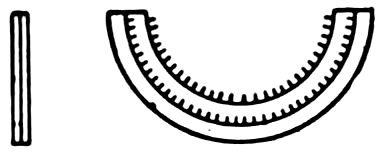
Fig. 126.—Profile for Brick Sewers.
In ground too soft to support the brickwork directly a cradle is prepared by placing profiles in position in the sewer and nailing 2–inch planks to these profiles, first firmly tamping earth under the planks. The bricks are laid in this cradle in a manner similar to that explained for sewers with a firm foundation. In still softer ground it may be necessary to construct a concrete cradle to support the bricks.
184. The Arch.—The arch centering consists of a wooden form made up of wooden ribs as shown in Fig. 127. The center 313conforms to the shape of the inside of the arch with allowance for the thickness of the lagging. The lagging is nailed on the ribs in straight strips parallel to the axis of the sewer. The center is supported on triangular struts resting against the sides and on the bottom of the sewer and is lifted into position by wedges driven between it and the support. The centers may be placed immediately after the completion of the invert, or a day or two may be allowed to pass to give the invert an opportunity to set. After the centers are fixed in place the arch brick are carried up evenly on each side and are pounded firmly into place. The center is usually, but not always “struck” immediately, and the arch brick are cleaned and pointed up from the inside. The outside is covered with a layer of ¼ to ¾ of an inch of cement mortar and may be backfilled to the top of the arch in order to maintain the moisture of the mortar during setting and to press the bricks of the arch together firmly. The centers are sometimes made collapsible so that they can be carried or rolled through the finished brickwork to the advanced position. In “striking” the centers the wedges are removed and the wings folded in.
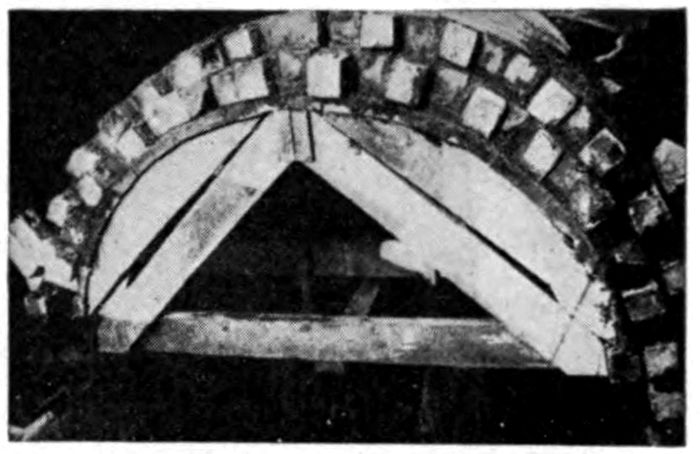
Fig. 127.—Centering for Brick Sewer.
In tunneling, the invert of the sewer is constructed in the same fashion as for open cut work. The arch centering is made in short sections and the bricks are put in position by reaching in over the end of the centering. All of the timbering of the tunnel is removed except the poling boards or lagging against which the bricks or mortar are tightly pressed, the boards being bricked in permanently.
185. Block Sewers.—Sewers made of unit blocks of concrete or vitrified clay are constructed in a similar manner to brick sewers. Fig. 128 shows the construction of a block sewer at Clinton, Iowa. In this sewer there are two rings; an inside one of solid blocks and an outside one of hollow blocks. Block sewers do not demand the skill in construction that is demanded by brick sewers, as the blocks are so cast that the joints are radial, whereas only experienced masons can lay bricks radially.
314
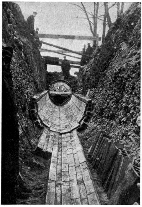
Fig. 128.—Segmental Block Sewer at Clinton, Iowa.
186. Organization.—The number of men employed on a brick or block sewer is proportioned according to the size of the sewer and the working conditions. The number of men working on different tasks usually bears the same ratio to the number of masons employed, regardless of the size of the work. These proportions are shown for different jobs, in Table 66.
TABLE 66
Organizations for the Construction of Brick and Block Sewers
Type of Work General Ratio on Basis of Four Brick Layers 15–foot, 5–ring Brick, Chicago 66–inch Circular Brick, Gary 84–inch Circular Brick, Gary 84– to 108–inch Sewer Brick in Detroit Tunnel 42–inch Lock-Joint Tile Block
Foreman 1 1 1 1 1 1
Brick layers 4 12 6 6 5 2
Helpers 2 11 3 3 1
Scaffold men 2 21 3
Brick tossers 2 7 15 2
Brick carriers 2 2 2
Cement mixers 2 6 6 5 1
Cement carriers 2 10 8
Form setters 1 3 3
Laborers 1 8 19 3 14 7
Source of Information Municipal Engineering, Vol. 54, p. 228 H. P. Gillette, Handbook of Cost Data
187. Rate of Progress.—In a general way it can be assumed that the laying of 1,000 bricks will require 3⅓ hours of the time of one mason, 10 man-hours for helpers and laborers, 2 barrels of cement, 0.6 cubic yard of sand, and about 10 feet board measure of centering. One thousand bricks will make about 2 cubic yards of brickwork. To the costs, as estimated on the basis of materials and labor, must be added about 15 per cent for overhead and an additional amount for the contractor’s profit. The number of bricks required in various size sewers is shown in Table 67. A mason can lay more bricks per hour in a large sewer than in a small one as there is a smaller percentage of face work, there is more room to work, and it is easier to lay the bricks radially. The number of bricks laid and the rate of progress on various jobs are shown in Table 68.
TABLE 67
Brick Masonry in Circular Sewers. Cubic Yards per Linear Foot
(From H. P. Gillette)
Diameter, Feet and Inches One Ring (4½ Inches) Two Ring (9 Inches) Three ring (13½ Inches)
2 0 0.103 0.240
2 6 0.125 0.280
3 0 0.147 0.327
3 6 0.169 0.371
4 0 0.191 0.415
4 6 0.213 0.458
5 0 0.234 0.501 0.802
5 6 0.256 0.545 0.867
6 0 0.278 0.589 0.933
6 6 0.633 1.000
7 0 0.677 1.063
7 6 0.720 1.128
8 0 0.763 1.193
8 6 0.807 1.260
9 0 0.851 1.325
9 6 0.895 1.390
10 0 0.938 1.456
Concrete Sewers
188. Construction in Open Cut.—In the construction of sewer pipe of cement and concrete one of two methods may be employed; 1st, to manufacture the pipe in a plant at some distance 315from the place of final use, or 2nd, to manufacture the pipe in place. The methods of the manufacture of cement and concrete pipe which are to be transported to the place of use are treated in Chapter VIII. The process of constructing the pipes in place is ordinarily used for pipes 48 inches or more in diameter. For smaller sizes, brick, vitrified clay, and precast cement pipes are usually more economical.
The preparation of the foundation of a concrete sewer is similar to that for a brick sewer. If the ground is suitable the trench is shaped to the outside form of the sewer and the concrete poured directly on it. In soft material which would give poor support to a sewer with a rounded exterior, the bottom of the trench is cut horizontal and a concrete cradle of poorer quality than that in the finished sewer is poured on the soft ground, on a board platform, on piles, or on cribbing supported on piles.
If the invert of the sewer is so flat that the concrete will stand without an inside form the shape of the invert is obtained 316by a screed or straight-edge which is passed over the surface of the concrete and guided on two centers, or on one center and the face of the finished work. The construction of a flat invert sewer at Baltimore is shown in Fig. 1. The center for the concrete is shown in the foreground. When the concrete for the next section is poured it will be smoothed to shape by a screed or straight-edge resting on the face of the finished concrete and the center. The center is shaped to conform to that of the finished concrete. It is firmly staked in position and acts as a bulkhead for the concrete as it is poured, as well as a guide for the screed.
317
TABLE 68
Rate of Progress on Brick Sewer Construction
(Based on 8–hour day)
Diameter of Sewer Shape Number Rings, Brick Number Masons Bricks per Mason per Day Number Laborers Feet Progress per Day Location Authority Remarks
7′ 0″ 8′ 11″ Circular and Oval 2½ 6 4710 39 60 Gary Gillette 9–hour day
4′ 0″ Circular 2 3 2500 36 Metcalf and Eddy General average
6′ 8″ Circular 3 arch 1 invert 18 62 Denver Gillette Concrete invert
2′ 9″ Egg 1 arch 2 invert 2 3 Springfield, Mass. Eng. Con., Jan. 16, 1907
5′ 6″ Circular 2 6 4570 35 110 Gary Gillette
6′ 6″ Circular 4 4800 Gillette Exceptional speed
2′ 9″ Circular 2 2 2080 5 13.9 Syracuse Gillette Tunnel 12–hour day
16′ 0″ Circular 5 8 5 cu. yd. 22 Chicago Gillette First year
16′ 0″ Circular 5 12 70–75 35 Chicago Gillette Second year
3′ 6″ Egg 2300 St. Louis Gillette
9′ 6″ Circular 3000 12.5 Chicago H. R. Abbott
3′ 6″ Circular blocks 2 13 30 Lock joint and tile. 10–hour day
318If inside forms are to be used they are made as units in lengths of 12 or 16 feet for wooden forms, and 5 feet for steel forms. The inside form is supported by precast concrete blocks placed under it and which are concreted into the sewer. It is held in position by cleats nailed to the outside form, to the sheeting, or wedged against the outside of the trench. In some cases, particularly where steel forms are used, the inside form is hung by chains from braces across the trench as is shown in Fig. 129. The form is easily brought to proper grade by adjustment of the turnbuckles and is then wedged into position to prevent movement either sideways or upwards during the pouring of the concrete. It may be necessary to weight the forms down to prevent flotation. Cross bracing in the trench which interferes with the placing of the form is removed and the braces are placed against the form until the concrete is poured. They are removed immediately in advance of the rising concrete.
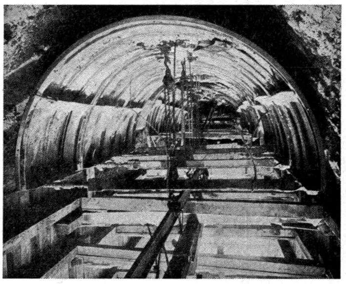
Fig. 129.—Blaw Standard Half Round Sewer Form, Suspended from Overhead Support. Courtesy, Blaw Steel Form Co.
The sewer section may be built as a monolith, in two parts, or in three parts. In casting the sewer as a monolith the complete full round inside form is fixed in place by concrete blocks and wires. The full round outside form is completed as far as possible without interfering too much with the placing and tamping of the concrete. The concrete is poured from the top, being kept at the same height on each side of the form, and tamped while being poured. The remaining panels of the outside form are placed in position as the concrete rises to them. An opening is left at the top of the outside arch forms which is of such a 319width that the concrete will stand without support. The casting of sewers as a monolith is difficult and is usually undesirable because of the uncertainty of the quality of the work. It has the advantage, however, of eliminating longitudinal working joints in the sewers which may allow the entrance of water or act as a line of weakness.
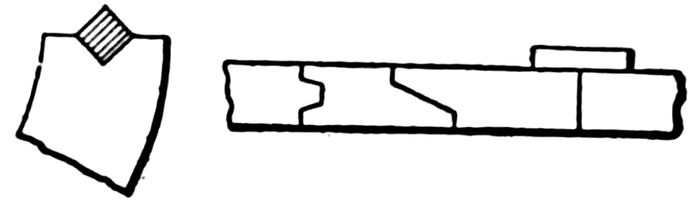
Fig. 130.—Construction Joints for Concrete Sewers.
If the sewer is to be cast in two sections the invert is poured to the springing line or higher. A triangular or rectangular timber is set in the top of the wet concrete as shown in Fig. 130. When the concrete has set the timber is removed and the groove thus left forms a working joint with the arch. After the invert concrete has set, the arch centering is placed and the arch is completed. This is the most common method for the construction of medium-sized circular sewers.
Large sewers with relatively flat bottoms are poured in two or three sections. First the invert is poured without forms and is shaped with a screed. About 6 inches of vertical wall is poured at the same time. This acts as a support for the side-wall forms. The side walls reach to the springing line of the arch and are poured after the invert has set. At the third pouring the arch is completed. The sewer shown in Fig. 1 is being poured in two steps, as the side walls are so low that they are poured at the same time as the invert. A transverse working joint similar to one of the types used in Fig. 130 is set between each day’s work.
The length of the form used and the capacity of the plant should be adjusted so that one complete unit of invert, side wall, or arch can be poured in one operation. The forms are left in place until the concrete has set. Invert and side-wall forms are generally left in position for at least two days, and in cold weather longer. The arch forms are left in place for double this time. For example if 20 feet of invert and arch can be poured in a day, 60 feet of invert form and 100 feet of arch form will be required. As the forms are released they must be moved forward through those in place. For this reason collapsible or demountable forms are necessary and steel forms are advantageous. Wooden arch forms are sometimes dismantled and carried forward in 320sections, but are preferably designed to collapse as shown in Fig. 131, so that they can be pulled through on rollers or a carriage.
189. Construction in Tunnels.—In tunnels the invert and side walls are constructed in the same manner as for open cut work. The tunneling, which acts as the outside form, is concreted permanently in place. The concreting of a tunnel by hand is shown in Fig. 132. If the work is to be done by hand the concrete is thrown in between the ribs of the arch centering and behind the plates or lagging, which are set in advance of the rising concrete. The lagging plates are 5 feet long which makes it possible to throw the concrete in place at the arch, and to tamp it in place from the end. A bulkhead and a well-greased joint timber are placed in position as the concrete rises.
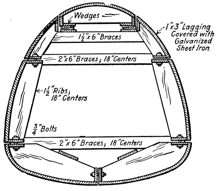
Fig. 131.—Section through a Collapsible Wood Form.
Pneumatic transmission of concrete is also used for filling the arch forms as well as the side walls and invert forms. In using this method the mixer may be placed at the surface or at the bottom of the shaft or other convenient permanent location which may be some distance from the form. The mixture is discharged into a pipe line through which it is blown by air to the forms. The starting pressure of about 80 pounds per square inch can be reduced after flow has commenced. In constructing the St. Louis Water Works tunnel the compressor equipment for moving the concrete had a capacity of 1,600 321cubic feet per minute at a pressure of 110 pounds. The tunnel is horseshoe shaped, 8 feet in height and with walls varying from 9 to 20 inches in thickness. The extreme travel of the concrete was 1,100 feet in an 8 inch pipe. The amount of air consumed at 110 pounds varied from 1.2 to 1.7 cubic feet of free air per linear foot of pipe. By the time the batch had been discharged the pressure had reduced to 25 to 40 pounds, depending on the length of the pipe. It is reported that a 6–inch pipe line would probably have given better results.
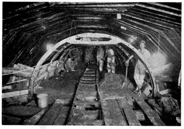
Fig. 132.—Ogier’s Run Intercepting Storm-Water Drain, Baltimore, Maryland. Placing concrete in Arch. The steel lagging of the forms is carried up in sections as the concrete is deposited. The drain is horseshoe shaped, and is 12 feet 3 inches high and 12 feet 3 inches wide.
The end of the concrete conveying pipe is provided with a flexible joint the simplest form of which can be made by slipping a section of pipe of larger diameter over the end of the transmission line. The concrete is deposited directly on the invert or into the side-wall forms and can be blown into the arch forms for 20 to 25 feet.
190. Materials for Forms.—The materials used in forms for concrete sewers are: wood, wood with steel lining, and steel alone. The first cost of wood forms is lower than that of steel but their life is relatively short. If the forms are to be used a number of times steel is more economical. With proper care 322and repairs steel forms will outlast any other material. Because of the increasing price of lumber and improvements in steel forms, wood forms are not frequently used. A common type of specification under which forms are used is:
The material of the forms shall be of sufficient thickness and the frames holding the forms shall be of sufficient strength so that the forms shall be unyielding during the process of filling. The face of the form next to the concrete shall be smooth. If wooden forms are used the planking forming the lining shall invariably be fastened to the studding in horizontal lines, the ends of these planks shall be neatly butted against each other, and the inner surface of the form shall be as nearly as possible perfectly smooth, without crevices or offsets between the ends of adjacent planks. Where forms are used a second time, they shall be freshly jointed so as to make a perfectly smooth finish to the concrete. All forms shall be water-tight and shall be wetted before using.
Any material in contact with wet concrete should be oiled or greased beforehand in order to prevent adherence to the concrete.
191. Design of Forms.—The design of forms for reinforced concrete work requires some knowledge of the strength of materials and the theories of beams, columns, and arches. Forms can be constructed without such knowledge but that they will be both economical and adequate is an improbability. The ordinary beam and column formulas are applicable to the design of forms. The maximum bending moment for sheeting and ribs is taken as wl2 8, where w is the load per unit length, and l is the length between supports. Sanford Thompson recommends that the deflection be calculated as wl3 128EI, in which E is the modulus of elasticity of the material, and I is the moment of inertia of the cross-section referred to the neutral axis. The horizontal pressure of the concrete against the forms has been expressed empirically by E. B. Smith,[101] as
P = H0.2R0.3 + 120C − 0.3S
in which P =323
lateral pressure in pounds per square inch;
R =
rate of filling forms in feet per hour;
H =
head of fill. Ordinarily taken as ½R, but in cold weather or when continuously agitated it may be as high as ¾R;
C =
ratio, by volume, of cement to aggregate;
S =
consistency in inches of slump.
Earlier investigators have usually concluded that the pressures were equal to those caused by a liquid weighing 144 pounds per cubic foot, but the tests of the United States Bureau of Public Roads, from which the above formula was devised, show the pressures to be decidedly below this amount under certain conditions.
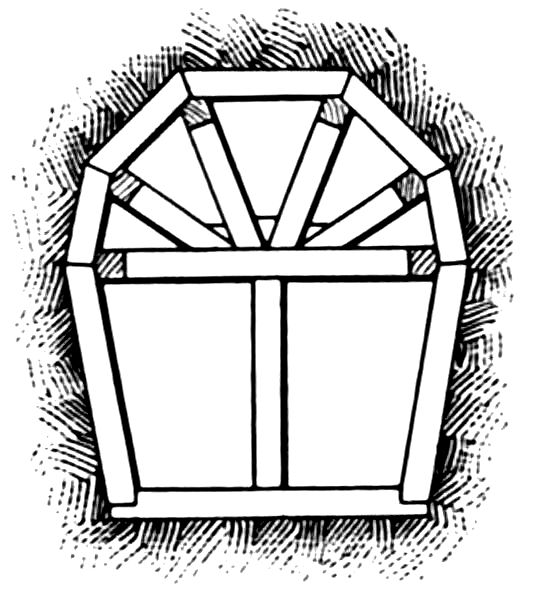
Fig. 133.—Centering for Large Forms.
With these units and formulas the design of the lagging becomes a matter of substitution in, and the solution of, the equations produced.[102] The forces acting on the ribs are indeterminate. No more satisfactory design can be made for the ribs than to follow successful practice, or what is seldom done, to determine the stresses in the forms by the application of one of the theories for the solution of arch stresses. The sizes of the lumber used in the ribs varies from 1½ × 6 inches to 2 × 10 inches, depending on the size of the sewer. If vertical posts are used at the ends to support the arch forms they are computed as columns taking the full weight of the arch. If the span is so wide that radial supports are used as shown in Fig. 133 the load at the center is assumed as one-fourth of the weight of the arch.
192. Wooden Forms.—Norway and Southern pine, spruce, and fir are satisfactory for form construction. White pine is satisfactory but is generally too expensive. The hard woods are too difficult to work. The lumber should be only partly dried as kiln-dried lumber swells too much when it is moistened, warping the forms out of shape or crushing the lagging at the 324joints. Green lumber must be kept moist constantly to prevent warping before use and when it is used it does not swell enough to close the cracks. The lumber should be dressed on the face next to the concrete and at the ends. Either beveled or matched lumber may be used for lagging. The joint made by beveled lumber shown in Fig. 134 is cheaper but less satisfactory than a tongued and grooved joint.
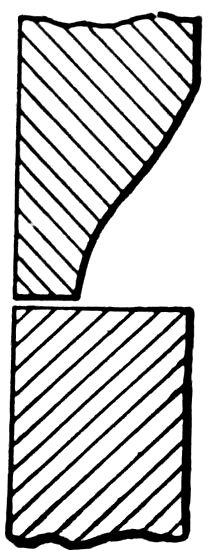
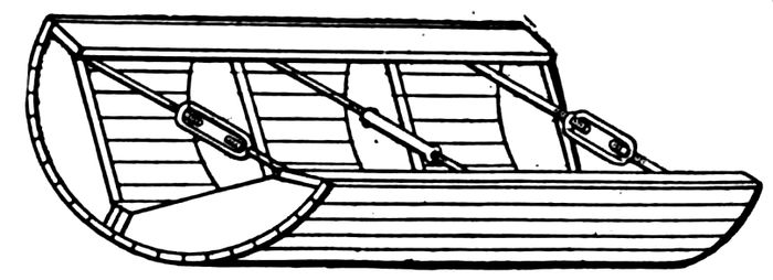
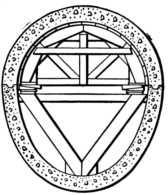
Fig. 134.—Beveled Joint for Wood Fords. Fig. 135.—Collapsible Wooden Invert Form for Concrete Sewers. Fig. 136.—Support for Arch Centering.
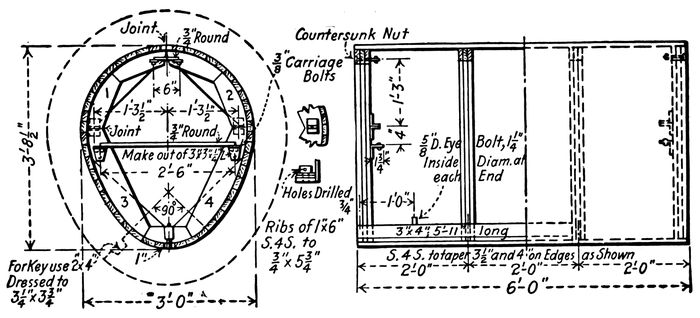
Fig. 137.—Wooden Forms Used in Tunnel, North Shore Sewer, Sanitary District of Chicago. Journal Western Society of Engineers, Vol. 22, p. 385.
Types of wooden forms are shown in Figs. 135 and 136 for use in sewers to be built as monoliths or in two portions. Fig. 137 shows the details of a built-up wooden form used in tunnel work for a 42½ inch egg-shaped sewer.
325193. Steel-lined Wooden Forms.—Sheet metal linings are sometimes used on wooden forms. They permit the use of cheaper undressed lumber, demand less care in the joining of the lagging, and when in good condition give a smooth surface to the finished concrete. Their use has frequently been found unsatisfactory and more expensive than well-constructed wooden forms because of the difficulty of preventing warping and crinkling of the metal lining and in keeping the ends fastened down so that they will not curl. Sheet steel or iron of No. 18 or 20 gage (0.05 to 0.0375 of an inch) weighing 2 to 1½ pounds per square foot is ordinarily used for the lining.
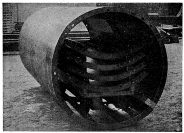
Fig. 138.—Blaw Standard Full Round Telescopic Sewer Forms, Showing Knocked-Down Sections Loaded on a Truck. Courtesy, Blaw Steel Form Co.
194. Steel Forms.—These are simple, light, durable, and easy to handle. The engineer is seldom called upon to design these forms as the types most frequently used are manufactured by the patentees and are furnished to the contractor at a fixed rental per foot of form, exclusive of freight and hauling from the point of manufacture. The forms can be made in any shape desired, the ordinary stock shapes such as the circular forms being the least expensive. The smaller circular forms are adjustable within about 3 inches to different diameters so that the same form can be used for two sizes of sewers. The same form can be used for arch and invert in circular sewers. Fig. 138 shows the 326collapsible circular forms and the manner in which they are pulled through those still in position. Fig. 129 shows a half round steel form swung in position by chains and turnbuckles from the trench bracing, and Fig. 139 shows the free unobstructed working space in the interior of some large steel forms.
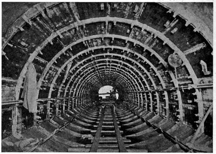
Fig. 139.—Interior of Steel Forms for Calumet Sewer, Chicago. Sewer is 16 feet wide. Note absence of obstructions. Courtesy, Hydraulic Steelcraft Co.
195. Reinforcement.—It is essential that the reinforcement be held firmly in place during the pouring of the concrete. A section of reinforcement misplaced during construction may serve no useful purpose and result in the collapse of the sewer. In sewer construction a few longitudinal bars may be laid in order that the transverse bars may be wired to them and held in position by notches in the centering and in fastenings to bars protruding from the finished work. This construction is shown in Fig. 1. The network of reinforcement is held up from the bottom of the trench by notched boards which are removed as the concrete reaches them, or better by stones or concrete blocks which are concreted in. Sometimes the reinforcement is laid on top of the freshly poured portion of the concrete the surface of which is at the proper distance from the finished face 327of the work. This method has the advantage of not requiring any special support for the reinforcement, but it is undesirable because of the resulting irregularity in the reinforcement spacing and position.
In the side walls the position of the reinforcement is fixed by wires or metal strips which are fastened to the outside forms or to stakes driven into the ground. Wires are then fastened to the reinforcement bars and are drawn through holes in the forms and twisted tight. When the forms are removed the wires or strips are cut leaving a short portion protruding from the face of the wall. The reinforcing steel from the invert should protrude into the arch or the side walls for a distance of about 40 diameters in order to provide good bond between the sections. The protruding ends are used as fastenings for the new reinforcement. The arch steel may be supported above the forms by specially designed metal supports, by small stones or concrete blocks which are concreted into the finished work; or by notched strips of wood which are removed as the concrete approaches them. Strips of wood are not satisfactory because they are sometimes carelessly left in place in the concrete resulting in a line of weakness in the structure. Metal chairs are the most secure supports. They are fastened to the forms and the bars are wired to the chairs. In some instances the entire reinforcement has been formed of one or two bars which are fastened into position as a complete ring. This results in a better bond in the reinforcement, requires less fastening and trouble in handling, but is in the way during the pouring of the concrete and interferes with the handling of the forms.
196. Costs of Concrete Sewers.—Under present day conditions a general statement of the costs of an engineering structure can not be given with accuracy. Only the items of labor, materials, and transportation that go to make up the cost can be estimated quantitively, and the total cost computed by multiplying the amount of each item by its proper unit cost obtained from the market quotations.
A summary of some of the items that go to make up the cost of a concrete sewer and the relative amount of these items on different jobs is given in Tables 69 and 70.
328
TABLE 69
Division of Labor Costs For the Construction of 96–inch Circular Concrete Sewer
Classification of Labor Classification of Work
Task or Title Number of men Total dollars per day Type of Work Dollars per foot
Superintendent 1 6.00 Excavation 1.80
Engineman 1 3.50 Sheeting and bracing 0.58
Hoister (engineman) 1 2.00 Bottom plank 0.17
Tag-men 2 3.30 Pulling sheeting 0.45
Earth diggers 10 16.50 Backfilling 0.33
On dump cars 2 3.30 Making and placing invert 1.17
Carpenter on bracing 2 3.00 Making and placing arch 1.54
Carpenters’ helpers 2 3.30 Laying brick in invert 0.29
Laying bottom 2 3.30
Moving pumps, etc. 2 3.30 Bending and placing steel in arch 0.20
Pulling sheeting 3 5.25
Mixing and placing concrete 16 26.40 Bending and placing steel in invert 0.09
On steel forms 3 5.25 Moving forms and centers 0.62
Water boy 1 1.00 Watchmen, water boy, etc. 0.62
Coal and oil 5.00
Total 90.40 Total 7.86
Notes.—Trench was 12½ feet wide and of various depths. At depth of 12 feet the cost of excavation was $1.61 per foot. From Engineering and Contracting, Vol. 47, p. 157.
Backfilling
197. Methods.—Careful backfilling is necessary to prevent the displacement of the newly laid pipe and to avoid subsequent settlement at the surface resulting in uneven street surfaces and dangers to foundations and other structures.
The backfilling should commence as soon as the cement in the joints or in the sewer has obtained its initial set. Clay, sand, rock dust, or other fine compactible material is then packed by hand under and around the pipe and rammed with a shovel and light tamper. This method of filling is continued up to the top of the pipe. The backfill should rise evenly on both sides of the pipe and tamping should be continuous during the placing of the backfill. For the next 2 feet of depth the backfill should be placed with a shovel so as not to disturb the pipe, and should be tamped while being placed, but no tamping should be done within 6 inches of the crown of the sewer. The tamping should become 329progressively heavier as the depth of the backfill increases. Generally one man tamping is provided for each man shoveling.
TABLE 70
Division of Costs For the Construction of Concrete Sewers
Gillette’s Handbook of Cost Data.
Item Location
Fond du Lac South Bend Wilmington Richmond, Indiana
Diameter in inches 30 66 53 54 48 42
Shape circular circular horseshoe circular circular circular
Plain or reinforced plain rein. rein. rein. rein. rein.
Cubic yards per foot 0.11 0.594 0.37 5″ shell 5″ shell 4″ shell
Daily progress, feet 47 24 to 36
Cost per foot, dollars 1.20 4.40 2.97 1.35 1.08 0.91
Per cent of total cost:
Labor 39.0[103] 33.5 33.0 17.1
Tools 1.5 11.5
Sand and gravel 12.4 15.5 18.9 19.3
Lumber 0.9
Water 0.7 11.5
Reinforcing 0.0 14.5 22.3
Cement 23.0 20.0 27.5 32.0[104]
Frost prevention 2.0
Forms 12.5 8.0 6.1 9.3
Engineering 8.0
Length of day, hours 8 10
Year of construction 1908 1906 Pre-war conditions
Above a point 2 feet above the top of the sewer the method pursued and the care observed in backfilling will depend on the character of the backfilling material and the location of the sewer. If the sewer is in a paved street the backfill is spread in layers 6 inches thick and tamped with rammers weighing about 40 pounds with a surface of about 30 square inches. One man tamping for each man shoveling is frequently specified. If no pavement is to be laid but it is required that the finished surface shall be smooth, slightly less care need be taken and only one man tamping is specified for each two men shoveling. On paved streets a reinforced concrete slab with a bearing of at least 12 inches on the undisturbed sides of the trench may be designed 330to support the pavement and its loads. This is of great help in preventing the unsightly appearance and roughness due to an improperly backfilled trench. On unpaved streets the backfill is crowned over the trench to a depth of about 6 inches and then rolled smooth by a road roller. In open fields, in side ditches, or in locations where obstruction to traffic or unsightliness need not be considered, after the first 2 feet of backfill have been placed with proper care, the remainder is scraped or thrown into the trench by hand or machine, care being taken not to drop the material so far as to disturb the sewer.
If the top of the sewer, manhole, or other structure comes close to or above the surface of the ground, an earth embankment should be built at least 3 feet thick over and around the structure. The embankment should have side slopes of at least 1½ on 1 and should be tamped to a smooth and even finish.
If sheeting is to be withdrawn from the trench it should be withdrawn immediately ahead of the backfilling, and in trenches subject to caving it may be pulled as the backfilling rises.
Puddling is a process of backfilling in which the trench is filled with water before the filling material is thrown in. It avoids the necessity for tamping and can be used satisfactorily with materials that will drain well and will not shrink on drying. Sand and gravel are suitable materials for puddling, heavy clay is unsatisfactory. Puddling should not be resorted to before the first 2 feet of backfill has been carefully placed. More compact work can be obtained by tamping than with puddling.
Frozen earth, rubbish, old lumber, and similar materials should not be used where a permanent finished surface is desired as these will decompose or soften resulting in settlement. Rocks may be thrown in the backfill if not dropped too far and the earth is carefully tamped around and over them. In rock trenches fine materials such as loam, clay, sand, etc., must be provided for the backfilling of the first portion of the trench for 2 feet over the top of the pipe. More clay can generally be packed in an excavation than was taken out of it, but sand and gravel occupy more space than originally even when carefully tamped.
Tamping machines have not come into general use. One type of machine sometimes used consists of a gasoline engine which raises and drops a weighted rod. The rod can be swung back and forth across the trench while the apparatus is being 331pushed along. It is claimed that two men operating the machine can do the work of six to ten men tamping by hand. The machine delivers 50 to 60 blows per minute, with a 2 foot drop of the 80 to 90 pound tamping head.