ON THE ARRANGEMENT OF GROUND CONDUCTORS.
Reading edition
In telegraphy, as well as in the question of lightning rods, attention has been but incidentally paid to the improvement of ground conductors, and this point has not been the object of that careful study that has been bestowed upon the establishment of aerial lines. It is only recently that the interest created by lightning rods has given rise to new forms of conductors differing from those formerly used. The publications of the Prussian Academy of Sciences of from 1876 to 1880 contain some information of special importance in regard to this. It is stated therein that the effect of ground conductors may be notably increased by the division of the earth plates and the use of metallic rods, without necessitating a greater output of material. These facts, however, have not as yet been put to profit in practice for the reason, perhaps, that the considerations, which have remained general, have not at once permitted of obtaining forms what could be employed with perfect knowledge of the results. This is what led Mr. Ulbricht, of Dresden, to make calculations for a few forms of conductors, and to test their approximate values. The results of these researches are printed in the Elektrotechnischen Zeitschrift for 1883 (p. 18).
The equations found show, in the first place, that there exist three means of obtaining a considerable effect, as regards the ground conductor, with a slight expenditure of material: The cylindrical electrode may be drawn out into the form of a bar or wire; the plate may be rendered narrow, and elongated in the form of a ribbon; and, besides, the annular plate may be enlarged in lessening the metallic surface.
Finally, a short, open cylinder with a vertical axis may be formed by curving a narrow plate or ribbon. It is not necessary to see the formula to recognize the fact that this cylinder must behave like a ribbon and a flat ring. The radius increasing, and the surface remaining constant, the resistance of the earth here likewise approaches zero.
As the resistance of the earth is inversely proportional to the diameter of the plates, the zero resistance can also be reached by dividing a plate ad infinitum. As the parts of the plate may be brought quite close to each other without perceptibly interfering with the action, a network has finally been reached by a division carried very far, yet limited, and by connecting the parts with one another by conducting cylinders.
If we seek to determine what forms of ground conductors are efficient and economical under given conditions, we shall have to begin by informing ourselves as to the choice of material to be used for the electrode, and shall then have to ascertain whether putting it in the ground will or will not necessitate much outlay. The most suitable material is copper, which may be used with advantage, in that it lasts pretty well underground, and that the facility which it may be worked permits of easily giving it more appropriate forms than those that can be obtained with cast iron, which is of itself less costly.
If the burying in the ground requires little or no labor, as when there exist ponds, rivers, and wells, or subterranean strata of water near the surface of the earth, elongated forms of conductors will be employed, such as the solid or hollow cylinder, the wire, the ribbon, the narrow ring, and the network. Plates approaching a square or circular shape are not advantageous. But if the ground has to be dug deeply in order to sink the conductor, the form of the electrode must be more condensed, and selected in such a way that the necessary action may be obtained with a minimum output of copper and labor. For great depths, and when the ground will permit of boring, an elongated and narrow cylinder will be used. Such a system, however, can only be employed when the cylinder is surrounded by spring water, since, without that, an intimate contact with earth that is only moist, cannot be obtained with certainty. In earth that is only moist and for moderate depths, preference may be given to an electrode laid down flat. The digging necessary in this case is onerous, it is true, but it permits of very accurately determining the state of the earth beneath and of obtaining a very perfect adherence of the electrode therewith. Two forms, the annular ribbon or the flat ring and the network, present themselves, according to calculations, as a substitute for copper plates, which are so expensive; and these forms are satisfactory on condition that the labor of digging be not notably increased. These forms should always have a diameter a little greater than that of the plate. The flat ring and the network, however, offer one weak point, which they possess in common with the plate, and that is, their dimensions cannot be easily adapted to the nature of the ground met with without a notable increase in the expense. Now, if the ground should offer a conductivity less than what was anticipated, and it were desired to increase the plate, say by one-third, it would be impossible to do so as a consequence of the closed form.
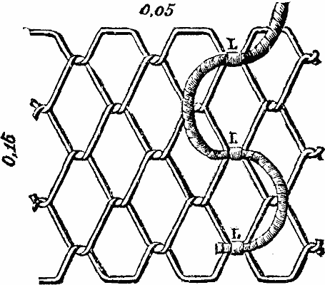
One important advantage is realized in this respect by combining the ring and the network in the form of a reticulated ring having a diameter of from 1 to 1½ meters. On cutting this ring at a given place and according to a certain radius we obtain the reticulated ribbon shown in the accompanying figure. The thickness of the wires is 2.5 mm., and their weight is 0.475 kilo. per meter. L, L, and L are the points at which the conducting cable is soldered. A reticulated ribbon of copper can be made in advance of any length whatever, and, according to local exigencies, it may be easily curved and given the form of a flat or cylindrical ring of varying width. Even though the ribbon has already been cut for a ring of given diameter, it may be still further enlarged by drawing it out and leaving a bit of the ring open, so as to thus obtain a nearly corresponding diminution in the resistance. Such a resistance may be still further diminished by rendering the ring higher, that is to say, by employing an annular cylindrical form.
After assuring himself, by experiments on a small scale, that calculation and observation gave concordant results for the flat ring, the author made an experiment on a larger scale with the annular network. For practical reasons he employed for this purpose a copper wire 2.5 mm. in diameter, which may be expected to last as long as one of iron plate 2 mm. in thickness. Calculation showed that in a ribbon 160 mm. wide, meshes 40 mm. in breadth were advantageous and favorable as regards rigidity. A reticulated ribbon like this, 4 meters in length, was made and formed into a flat ring having an external diameter of 1.42 m. and an internal one of 1.10 m. The resistance of this ring was found to be W = 0.3485 1/k, and that of a plate one meter square, W0 = 0.368 1/k.
As the conductivity of the earth is very variable, and as we cannot have an absolute guarantee that the ramming will be uniform, it seemed proper to make the measurements of the resistance by fixing the plate and the ring in succession to the lower surface of a small raft, in such a way that the contact with the water should correspond as well as possible to the suppositions made for the calculation. As a second ground conductor, a system of water pipes was used, and, after this, a lightning rod conductor, etc.
Repeated and varied experiments gave, for the calculation of the values of the resistances, equations so concordant that the following results may be considered very approximate.
The square plate had a resistance of 35.5 Siemens units, and the reticulated ring one of 32.5. From the first figure we deduce k = 1/91.12, that is to say, the specific conductivity of river-water is 1:91120000. Calculation, then, gives as the resistance of the earth in Siemens units:
CalculatedObserved.
Square plate. 33.5 33.5
Annular ring. 31.76 32.5
These figures prove the accuracy of the calculations that had been made in an approximate way.
The experiments were performed upon the Elba, above Dresden. Other experiments still had reference to the influence of immersion. In order to diminish polarization, only instantaneous currents from the measuring pile were employed. It was to be supposed that the current of water through which the bubbles of gas were removed from the electrodes would not have permitted of a notable resistance of polarization. Later measurements, made upon a ribbon buried, like the plates, in the earth, gave likewise most favorable results.
As a result of these experiments, the State railways of Saxony have, in such cases as were practicable, introduced the annular network of copper. There are some manufacturers, too, who seem desirous of adopting this system, although it has hardly emerged from the period of experiment. The pecuniary advantages that will result from an application of it ought, it would seem, to dispel a large proportion of the criticisms directed against the erection of lightning rods, from the standpoint of expense, and contribute to extend an arrangement which may be considered as a very happy one.
If we compare the square plate with the equivalent annular network, constructed as above indicated, and which should possess, according to the author an external diameter of 1.26 m. and of 3.45 m., we find that:
The square plate,1 mm. thickweighs 8.9 kilos.
"2 mm. thickweighs 17.8 kilos.
The annular networkweighs 1.64 kilos.
The cost of reticulated ribbon per meter amounts to about 4.4 francs, supposing it to be arranged as shown in the cut.
As term of comparison, we may admit that the following forms are nearly the equivalent of a horizontal, unburied plate one meter square.
Length.Diameter.
Vertical cylinderburied1.40 m.0.13 m.
""1.80 m.0.06 m.
Vertical bar"2.60 m.0.013 m.
Horizontal bar"5.20 m.0.013 m.
Horizontal flat ring 1.32 m. in external diameter, and 1.08 m. internal.
Horizontal network 1.01 m. square, and having meshes of the same size as those of the reticulated ribbon.
Horizontal reticulated ribbon 3 m. in length and of the structure described.
Horizontal annular ring 1.26 m. in external diameter, 0.94 m. internal.
In conclusion, let us meet an objection that might be made to the accuracy of the hypotheses that serve as a base to the preceding calculations, in cases where ground plates for lightning rods and not for telegraphs are concerned. Between the two ground plates of a telegraph line there is generally a distance such that the curves of the current undergo no deviation in the vicinity of one of the electrodes (the only part important for integrations) through the influence of the other. But it might be admitted that such would prove the case with a lightning rod in a storm, at the time of the passage of the fluid into the earth. The ground plate here is one of the electrodes, and the other is replaced by the surface of the earth strongly charged to a great distance under the storm clouds. If we suppose (what may be admitted in a good lightning rod) that there no longer occurs any spark from the point downward, the curves of the current, in starting perpendicularly from the ground plate, would be obliged to leave their rectilinear trajectory and strike the surface of the earth at right angles. When the electricity flows through a plane surface into an infinite body, it is only when such surface presents a very great development that the respective potentials decrease very slowly in the vicinity of the said surface. No notable modification occurs, then, in the curves of equal potential, in the vicinity of the ground plate through the action of this extended charge, nor consequently any modification in the curves of the current; but the electricity which spreads has but a short distance to travel in order to overcome the most important resistances.
The calculations of resistances given above have, then, the same value for discharges of atmospheric electricity.—Bull. du Musee de l'Industrie.