Part 2 — CASE HISTORY NO. 6 How Can We Repair an Orbiting Satellite?
Reading edition
E. Jared Reid Electrical Engineer—Member of Staff, Satellite Design Department
THE PROBLEM
It is hard enough to fix a new piece of scientific equipment when it goes out of order in the laboratory. And when the equipment is sailing around the earth a couple of thousand miles up in the sky a repair job ought to be impossible. But during the last two months of 1962 we found this not to be true at all. That was when the Telstar I satellite began to misbehave and eventually would not obey the commands we sent it from the ground. This presented us with a nice little problem: We had to find out exactly what was wrong with the satellite and then—the really tough job—devise a way to cure the trouble. We were able, finally, to do both these things, after a combination of logical deduction, trial-and-error experimentation, and laboratory testing—plus a certain amount of plain good luck. Our “cure,” unfortunately, turned out to be only a temporary one, for our patient had a relapse some weeks later. However, the story of how we went about doing our never-before-attempted task should give you an idea of the things you have to improvise in the laboratory when an experiment doesn’t work out exactly as you had planned.
79
The Telstar Command Circuit
As shown on pages 32 and 33, the operation of the Telstar I satellite was controlled by orders sent from the ground on a frequency of 123 megacycles. Fifteen different commands could be given to the satellite, each a coded signal made up of a series of ones and zeros. The signals, as you can see in the table below, turn on or off the radiation experiments, the telemetry, the communications equipment, and the orientation coil. These are important functions, and we wanted them to be going on when they were needed. But we did not want them to be operating continuously.
Command was the only Telstar I function that we felt had to be “redundant,” so two duplicate chains of components were provided. As you can see in the block diagram on the next page, the satellite has two radio receivers in parallel, so that one can operate if the other fails. There are also two command decoders, which take the pulse-coded signals from the receivers and translate their zeros and ones into usable instructions. In the command switching control, these instructions operate nine relays that turn on or off the power to all the electronic circuits except the command receiving chain, which operates continuously.
Telstar I’s telemetry unit reported back 112 measurements every minute over the 136-megacycle frequency. These told both what the satellite encountered in space and the condition of the satellite’s own components—as indicated by a variety of different sensors. The telemetry also gave a check on whether the commands sent to the satellite were actually obeyed.
The Fifteen Telstar Commands
COMMAND FUNCTION
A Turns on traveling-wave tube filament voltage
B Turns on traveling-wave tube helix and collector voltages; energizes all transistor circuits associated with communications experiments
AA Turns off traveling-wave tube helix, collector, and filament voltages; de-energizes transistor circuits
C Turns on traveling-wave tube by applying anode voltage
CC Turns off traveling-wave tube anode voltage
D Turns on telemetry and energizes radiation experiment circuits
DD Turns off telemetry and de-energizes radiation experiment circuits
E Turns on current in orientation torque coil
EE Turns off current in orientation torque coil
F Connects telemetry encoder No. 1 to circuit
FF Connects telemetry encoder No. 2 to circuit
SS Performs duties of AA, CC, DD, EE, and FF; de-energizes 136-mc beacon transmitter and removes all load from storage battery
S Connects storage battery back into the circuit and energizes the 136-mc beacon transmitter
T1 Turns off command receiver and decoder No. 2 for 15 seconds, so that command receiver and decoder No. 1 can be tested
T2 Turns off command receiver and decoder No. 1 so that No. 2 can be tested
80
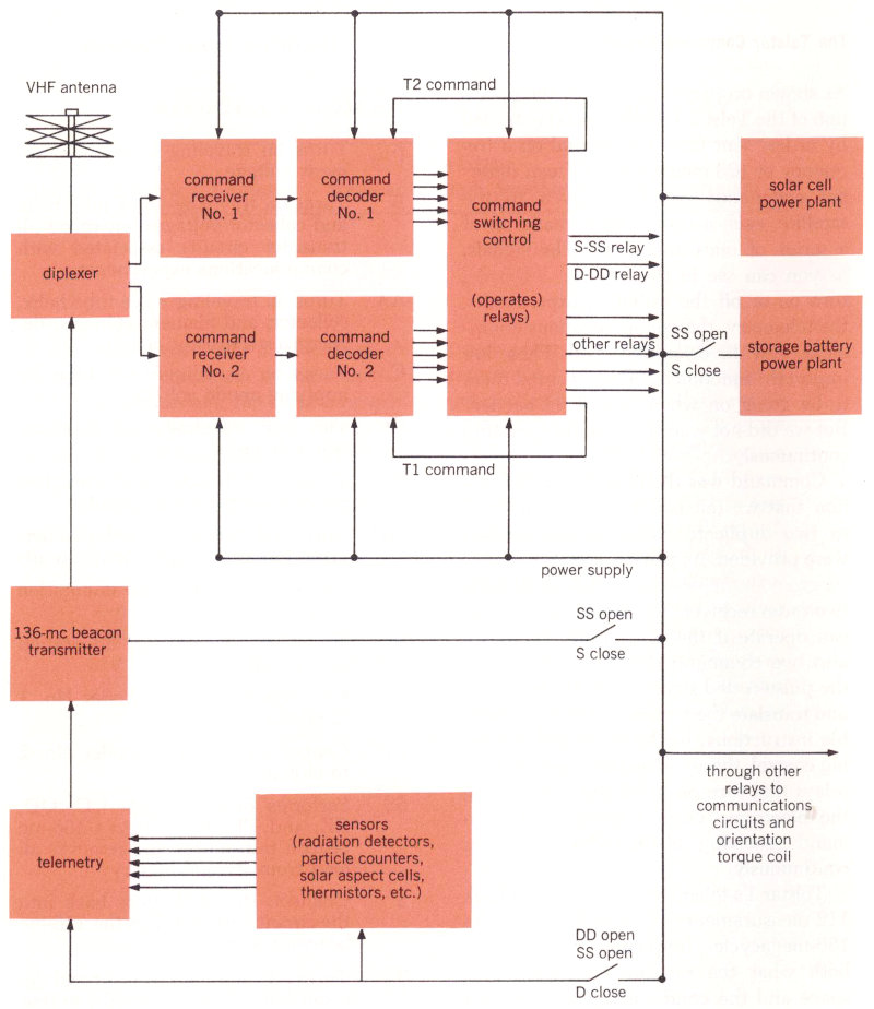
This block diagram of Telstar I’s command circuit shows the redundant receiver and decoder chains, No. 1 and No. 2, which are fed the command signals from the ground that are picked up by the VHF antenna. Decoded instructions go to the command switching control, which operates relays to turn equipment on or off. Reports on the operation of this control are sent back by telemetry to the ground station along with information from the satellite’s sensors.
VHF antenna
diplexer
command receiver No. 1
command decoder No. 1
T1 command
command receiver No. 2
command decoder No. 2
T2 command
command switching control (operates relays)
S-SS relay
D-DD relay
other relays
136-mc beacon transmitter
SS open
S close
telemetry
DD open
SS open
D close
sensors (radiation detectors, particle counters, solar aspect cells, thermistors, etc.)
power supply
solar cell power plant
storage battery power plant
SS open
S close
through other relays to communications circuits and orientation torque coil
81
What Went Wrong With Telstar I
During Telstar I’s first two months in orbit, the only indication of trouble cropped up in one of the command operations. Telemetry told us that the satellite was no longer executing the T2 command. This meant that we could not temporarily disconnect command chain No. 1 to check the performance of chain No. 2. Then, a short while later, No. 2 began to give intermittent operation. Finally it failed completely. At the time, we didn’t know why this had happened, but, since the satellite’s other command chain still seemed to be operating normally, we were not very worried.
However, in the middle of November 1962 command chain No. 1 also began to be intermittent. We would send a command but get no response from the satellite; only after we repeated it a few times would the satellite finally do what it had been told to do. Now there was something to be concerned about. And, if chain No. 1 should fail, we had to make sure that Telstar would be left in a favorable operating condition. We didn’t want the satellite’s communications equipment to be left on without our being able to turn it off—this would keep a continuous drain on the power supply.
As we feared it would, the other command circuit went out of commission on November 23rd. However, when this happened, the communications circuits had been turned off, although the command chains themselves and the telemetry remained on. This meant that we could still try to send commands, the condition of the satellite could still be monitored by telemetry, and the solar cells could still supply useful power. But, since we could not turn the communications equipment on, Telstar I could no longer be used for transatlantic television or any of the experiments we had been carrying on successfully since July.
Looking for the Trouble Spot
At this point a number of Bell Telephone Laboratories engineers began to analyze Telstar’s troubles. As you can imagine, we had a rather difficult problem. We obviously could neither go up and look at Telstar nor bring it down for an overhaul on the ground. We could only send different commands to the satellite and watch the telemetry data to see what, if anything, happened.
After checking the satellite’s other equipment, we were happy to find that everything except the command chains was in good condition. So we decided the trouble had to be one of five possibilities:
excessive electronic “noise” in the satellite, which had blocked the command receivers;
extreme temperature variations, which had caused a joint to expand, contract, and finally break;
a loose connection;
slow aging of an electronic component;
deterioration of a component from excessive radiation bombardment.
We could quickly narrow this list down. Telemetry indicated that the receiver was not being blocked by noise. Reports from the temperature-measuring thermistors told us that inside the satellite the temperature was 75 degrees Fahrenheit, just as it should be. A loose connection was very unlikely, because every one had been made by expert wiremen, examined by trained inspectors, and then completely encapsulated in polyurethane foam. Aging also seemed very improbable, since all the components had been individually tested and selected for the highest reliability and longest life.
82
The Villain: Radiation
This left only radiation damage. We had other good reasons to suspect this, too. As far back as October 1961, scientists at Bell Labs and Brookhaven National Laboratories had made an important discovery about the effect of radiation on a transistor. They found that, when radiation penetrates the outer shell of a transistor and ionizes the gases inside, electrically charged particles (ions) tend to collect on the surface and change the transistor’s electric properties. This effect is particularly noticeable when a transistor is operating under reverse bias voltage. We knew that some of the 37 transistors used in each Telstar I decoder circuit were operating under continuous reverse bias and that they also had less metal shielding than did those semiconductors in the telemetry and receiver circuits.
Telstar’s radiation detectors had been telling us that the concentration of high-energy electrons near the inner edge of the Van Allen belt was greater than we had expected. We now know this may have come as a result of man-made high-altitude nuclear explosions, one of which took place the day before Telstar I was launched. But we had had no reason to anticipate this extra radiation—it was more than one hundred times the predicted level—when we tested the transistors to be used in Telstar I. So we were not too surprised that they were more susceptible to radiation damage than we had thought they would be.
All this seemed to give us a theoretical explanation for the trouble. So, after November 23rd, we began looking for laboratory evidence to confirm our radiation theory. First, two engineers traveled down to Johannesburg, South Africa. At this time the highest point of Telstar’s orbit—when it passes through the least Van Allen belt radiation—was over the southern hemisphere, and it seemed a good idea to command the satellite when it was under the condition of lowest radiation and see if anything would happen. However, everything the engineers tried proved fruitless.
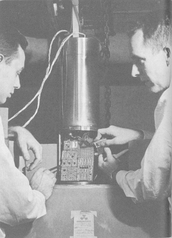
A duplicate of one of Telstar I’s command decoders, containing 37 transistors and 191 diodes, being placed in a small elevator that will lower it into a gamma radiation chamber.
At our Murray Hill, New Jersey, laboratories we worked on a different approach. We exposed transistors like those used in the decoders to large doses of radiation. We also exposed entire spare decoder units to accelerated radiation to find out where their weakest points were (see illustration). And then we built and 83 tested decoders using radiation-resistant transistors to see if they worked better. After a week of intensive laboratory work, we had some pretty good evidence. The tests of individual transistors definitely showed that heavy radiation would cause them to deteriorate. Testing of the complete decoders also led to some failures, and, when we analyzed them, they turned out to be the kind that would be caused by faulty transistors. We also discovered that the most sensitive part of a decoder circuit was the zero gate, which recognizes the zeros in the one-and-zero code that commands the satellite.
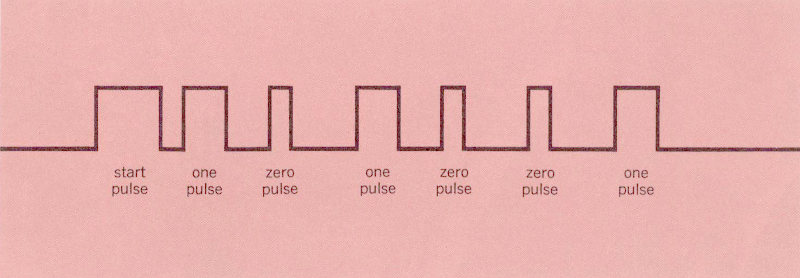
A typical command signal sent to Telstar I. It consists of seven pulses: a three-unit “start” pulse and a binary code made up of three two-unit “one” pulses and three one-unit “zero” pulses.
Fooling the Decoder
Now we thought we knew the guilty component, but the hardest job still lay ahead of us. We had to do something to the commands so that they would bypass this troublesome zero gate. Each of the fifteen satellite commands is a binary code of seven pulses, as illustrated in the diagram above. The first—the start pulse—is three units wide. Then follow six more pulses of which three are two units wide (one pulses) and three are one unit wide (zero pulses). The arrangement of this group of six ones and zeros determines the particular command.
Each time a one pulse arrives at the decoder, a one gate counts the pulse and stores a one in its memory. A zero gate counts the zero pulses, but does not store anything. So, if the zero gate is blocked, the decoder will not count the zeros in any of the coded commands and thus cannot decode them properly.

The special “notched one” pulse that was invented to fool Telstar I command decoder.
What could be done about this? The answer seemed to be to devise a new type of pulse—a pulse that would be enough like a one so that it would pass through the one gate and advance the counter, but, at the same time, be enough unlike a one so that the one gate would not store it in its memory. This led to the invention of the special long pulse with a dip or notch in it that is shown in the diagram above. When we tested it in the laboratory 84 on one of the duplicate decoders we had exposed to radiation, this new notched pulse worked as we hoped it would. It passed through the one gate and advanced the counter, but was not stored as a one in the one gate’s memory. Thus it fooled the decoder by doing just what a zero is supposed to do, even though it had gone through the one gate rather than the zero gate.
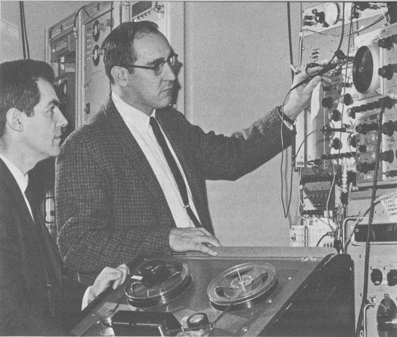
Magnetic tapes of special codes using notched ones in place of zeros being prepared for use.
But the real test was yet to come. Special modified signals for two of the fifteen Telstar commands, using our new notched ones in place of the usual zeros, were put on magnetic tape (see photograph). Then, on December 20th, when Telstar made its 1492nd pass over Andover, Maine, a group of tired engineers huddled about the mass of equipment they had assembled. Finally, on the third try, the notched pulses were successful; Telstar’s telemetry flashed back the word that the proper relay had operated upon command.
Removing the Ionization
We now wanted to get Telstar to do something that had seemed to work in the laboratory. The transistors most affected by radiation were those operating under continuous reverse bias, to whose surfaces unwanted ions were attracted. If we removed the voltage from these transistors, we felt that the ionization layer would be dissipated, and they would act normally again. Our plan was to prepare a complete taped program of all fifteen commands, and carefully disconnect Telstar’s storage battery (using command SS). Then, when the satellite went into eclipse, there would be no power available from the solar cells either, and—if our calculation was right—the 85 complete lack of voltage ought to restore the transistors to working order. This was a hazardous procedure, for if something went wrong we might have a completely silent satellite on our hands.
As it turned out, an accident did happen—but one of a different and much more fortunate kind. On December 27th Telstar misinterpreted our “trick” commands and disconnected its own battery before we asked it to. Then, as the satellite went into the earth’s shadow, we held our breath while all its power stopped and the telemetry went silent. But, as we had hoped, a rest period with all power removed from the deteriorated transistors apparently made them work almost normally once again. On January 1, 1963, we were able to disconnect the battery in regular fashion—that is, using the one-and-zero code. After this was done, and all power had been removed, both decoders again would operate when given normal commands (actually, the first one restored to duty was decoder No. 2, which had gone out of order first, back in August).
Back to Normal—For a Time
For more than a month Telstar I behaved as it should, and our communications experiments, including television broadcasts, were resumed on January 3rd. During this time we used both normal commands and our special notched-pulse modified commands. Whenever normal commands became intermittent we used the modified commands to disconnect the battery for several eclipses.
Our good fortune, however, did not last. Continued exposure to radiation apparently led to further damage to Telstar I’s transistors. By February 14th, disconnecting the storage battery no longer returned the decoder to normal, and we could operate only with our modified commands. And, on the 21st, the satellite apparently misinterpreted a command, disconnected its storage battery, and went silent. Since then, none of our modified commands has been able to bring back its voice. There is still a possibility that Telstar I may recover if it remains out of the high-radiation part of space for a long enough period—but as time goes by this appears less likely.
However, our work was not in vain. Because we pinpointed the effects of radiation on the transistors in Telstar I, this problem was counteracted on the Telstar II satellite launched on May 7, 1963 (see page 31). To avoid the worst of the radiation effects, the second Telstar is in a considerably larger orbit, which causes it to spend less time in the heaviest high-energy Van Allen belt regions. It carries new radiation detectors with much greater measuring capacity. And in one of Telstar II’s command decoders we are using a new type of transistor, which we hope will not be affected nearly as much by radiation as were the ones in Telstar I’s ill-fated decoders.
E. Jared Reid was born in Hartford, Connecticut, and received a B.S. from Trinity College in 1956, a B.E.E. from Rensselaer Polytechnic Institute in 1957, and an M.E.E. from New York University in 1959. He joined Bell Telephone Laboratories in 1957, and has worked on the design and testing of the Time Assignment Speech Interpolation (TASI) system for the transatlantic cable, as well as on transistor circuits for the Telstar satellite.
86
A Final Note to the Reader
Now, having read Part II of Satellite Communications Physics, you should have an idea how we predict the orbit of an artificial satellite and how we find out where it points while passing a thousand miles above our heads. You can see how we pick the best material to cover its surface with and how we protect its solar cells from the hazards of space. And you have watched the steps we would take when our satellite stops working properly.
It would, we admit, take a little more experience to solve problems like these on your own—and to deal with all the other complications of satellite communications. But we hope our brief glimpses into the laboratory have shown what this experience might be like. Our six case histories have only scratched the surface, but they should give you a good idea of the fascinating work that goes into practical science and engineering. They should show that something like Project Telstar doesn’t succeed only because of far-sighted, imaginative thinking—nor only because of ingenious engineering. It draws upon the best of both of these.
Along the way, we hope you have noticed some important guideposts—things like Newton’s law of gravitation, the law of reflection of light, the Stefan-Boltzmann law. They typify the basic principles of physics that engineers and scientists, whatever they do, must always keep in mind. No matter how exotic or up-to-the-minute the application, the ground rules of physics must be followed. If we have convinced you of this, we have done what we set out to do!
87
Suggested Reading
If you would like to read further about satellite communications in general or get some information about the case histories in Part II, you may be interested in using the following reading list. The references under each of the subheadings are listed chronologically; they include books, reports, technical papers, and magazine articles. As you can see, some of these ought to be understandable by almost anyone, but others are quite technical in nature.
For further background in the basic physical principles that are discussed in Part II, you may refer to many good high school and college physics texts. An increasing number of useful physics books—both originals and reprints—are now being published in paperback form.
Satellite Communications
Arthur C. Clarke, “Extra-Terrestrial Relays—Can Rocket Stations Give World-Wide Radio Coverage?,” Wireless World, October 1945, page 305.
John R. Pierce, “Orbital Radio Relays,” Jet Propulsion, April 1955, page 153.
John R. Pierce and Rudolf Kompfner, “Transoceanic Communication by Means of Satellites,” Proceedings of the I.R.E., March 1959, page 372.
John R. Pierce, “Exotic Radio Communications,” Bell Laboratories Record, September 1959, page 323.
Steven M. Spencer, “Dial ‘S’ for Satellite,” The Saturday Evening Post, January 14, 1960, page 13.
Space Electronics Issue, Proceedings of the I.R.E., April 1960.
William Meckling, “Economic Potential of Communication Satellites,” Science, June 16, 1961, page 1885.
Special Issue on Project Echo, Bell System Technical Journal, July 1961.
C. C. Cutler, “Radio Communication by Means of Satellites,” Planetary and Space Science Journal, July 1961, page 254.
W. C. Jakes, Jr., “Project Echo,” Bell Laboratories Record, September 1961, page 306.
John R. Pierce, “Communication Satellites,” Scientific American, October 1961, page 90.
United States Senate, Committee on Aeronautical and Space Sciences, Communication Satellites: Technical, Economic, and International Developments (staff report), U. S. Government Printing Office, Washington, 1962.
L. J. Carter, editor, Communications Satellites, Academic Press, New York and London, 1962.
“Situation Report on Communications Satellites,” Interavia, June 1962, page 749.
Leonard Jaffe, “Communications by Satellite,” International Science and Technology, August 1962, page 44.
“Communicating by Satellite,” Business Week, October 27, 1962, page 86.
Project Telstar
Rowe Findley, “Telephone a Star,” National Geographic, May 1962, page 638.
Louis Solomon, Telstar, McGraw-Hill Book Company, New York, 1962.
Special Telstar Issue, Bell Laboratories Record, April 1963.
Special Telstar Issue, Bell System Technical Journal, July 1963.
88
Satellite Communications Case Histories
1. How Do We Calculate a Satellite’s Orbit?
Mario Iona, “Satellite Orbits,” The Physics Teacher, May 1963, page 55.
A. J. Claus et al., “Orbit Determination and Prediction and Computer Programs,” Bell System Technical Journal, July 1963, page 1357.
2. What Color Should a Satellite Be?
P. T. Haury, “Thermal Design of the Electronics Canister,” Bell Laboratories Record, April 1963, page 161.
J. W. West, “Space Hardware Aspects of the Satellite,” Bell Laboratories Record, April 1963, page 167.
Peter Hrycak, et al., “The Spacecraft Structure and Thermal Design Considerations,” Bell System Technical Journal, July 1963, page 973.
3. How Do We Make Optical Measurements on a Satellite?
W. C. Jakes, Jr., “Participation of the Holmdel Station in Project Telstar,” Bell System Technical Journal, July 1963, page 1421.
4. How Do We Keep Solar Cell Power Plants Working in Space?
D. M. Chapin et al., “The Bell Solar Battery,” Bell Laboratories Record, July 1955, page 241.
G. R. Frost, From Sun to Sound, Bell Telephone Laboratories, New York, 1961.[6]
F. M. Smits, K. D. Smith, and W. L. Brown, “Solar Cells for Communications Satellites in the Van Allen Belt,” Journal of the British I.R.E., August 1961, page 161.
D. M. Chapin, Energy from the Sun, Bell Telephone Laboratories, New York, 1962.[6]
R. E. D. Anderson et al., “The Satellite Power System,” Bell Laboratories Record, April 1963, page 142.
K. D. Smith et al., “The Solar Cells and Their Mounting,” Bell System Technical Journal, July 1963, page 1765.
5. Would Time Delay Be a Problem in Using a Synchronous Satellite?
G. M. Phillips, “Echo and Its Effect on the Telephone User,” Bell Laboratories Record, August 1954, page 281.
W. A. van Bergeijk, J. R. Pierce, and E. E. David, Jr., Waves and the Ear, Anchor Books (Science Study Series paperback), Doubleday & Company, New York, 1960.
R. P. Haviland, “The Synchronous Satellite,” in Communications Satellites, L. J. Carter, editor, Academic Press, New York and London, 1962, page 113.
6. How Do We Repair an Orbiting Satellite?
D. S. Peck et al., “Surface Effects of Radiation on Transistors,” Bell System Technical Journal, January 1963, page 95.
“Fixing Up Telstar,” Time, January 18, 1963, page 48.
E. P. Moore and W. J. Maybach, “Satellite Command and Telemetry Systems,” Bell Laboratories Record, April 1963, page 156.
J. S. Mayo et al., “The Command System Malfunction of the Telstar Satellite,” Bell System Technical Journal, July 1963, page 1631.
Note: The Bell Laboratories Record is published by Bell Telephone Laboratories, Incorporated, 463 West Street, New York 14, New York. The Bell System Technical Journal is published by the American Telephone and Telegraph Company, 195 Broadway, New York 7, New York.
The Editor
Ronald M. Foster, Jr., was born in Plainfield, New Jersey, and received an A.B. degree from Harvard College in 1948. He joined Bell Telephone Laboratories in 1956, and is a member of the Educational Aids Department of the Public Relations and Publication Division. He is engaged in development of material for the Bell System Aid to High School Science Program.