Part 2 — CASE HISTORY NO. 3 How Can We Make Optical Measurements on a Satellite?
Reading edition
Jeofry S. Courtney-Pratt Physicist—Head, Mechanics Research Department
THE PROBLEM
Since the first Telstar satellite went into orbit, we have tried to trace its path through space precisely. But we also have had to keep a constant check on the position, or attitude, that the satellite takes as it travels. We are particularly interested in the direction of the spin axis about which it revolves, and we also want to know its spin rate, which is the number revolutions the satellite makes each minute. Although these might seem relatively simple jobs, they actually turned out to be rather complicated. And only at virtually the last minute, just before the satellite’s design was finally set, did we think of a new way of using reflected flashes of sunlight to report on its spin axis and spin rate.
Why We Want to Know About the Spin Axis
When the satellite was injected into its orbit, it was spin-stabilized to keep it from tumbling over and over, much as a rifle bullet is stabilized by being spun about its longitudinal axis. The Telstar satellite is roughly spherical, and it was designed to spin with the helical antenna end as its north pole and the antenna bands as its equator. On July 10, 1962, the satellite was given an initial spin of 177.7 revolutions a minute. As we expected, this rate is decreasing gradually; after two years it will only be spinning one tenth as fast.
The most important reason for keeping a close watch on the satellite’s spin axis is to make sure that microwave signals are sent and received steadily. It isn’t possible to build an antenna that radiates at exactly the same power in all directions. Telstar’s antennas work very well, but they operate better in the direction of the satellite’s equator than they do towards its poles. This means that if the spin axis is constantly changing transmission will fade in and out—even at times passing through “null” where no transmission at all is possible. No single fixed orientation is perfect for the spin axis, but we decided that the best average position would be to keep it always perpendicular to the plane of the earth’s orbit. We tried to make sure that the spin axis would not vary by more than five degrees from this direction at any time—although it probably could depart as much as 15 or 20 degrees without doing serious harm.
A second reason for being careful about the satellite’s spin axis is the problem of 54 heat balance. If one end of the satellite points constantly at the sun and the other end does not, the end near the sun will get much too hot and the other will get much too cold. Therefore, we tried to fix the spin axis so that it stayed perpendicular to a line drawn from the satellite to the sun.
We also wanted to get a continuing report on the effects of the magnetic field of the earth at high altitudes. We knew these would cause the spin axis to change with time, or precess, but we couldn’t be exactly sure what these changes would be.
Since the orientation of Telstar’s spin axis was so important we installed a torque coil in the satellite. This is a coil of wire in which, upon a signal from the ground, an electric current can be made to flow. The current produces a magnetic field that interacts with the earth’s magnetic field to change the position of the satellite’s spin axis. However, we could not be sure that this device would work properly—and this is another reason why we wanted to keep track of the exact position of the spin axis.
Ways of Measuring the Spin Axis
One of the devices built into Telstar is a set of six solar aspect cells spaced at regular intervals around the satellite. These give a fairly accurate indication of the angle between the spin axis of the satellite and a line joining the satellite and the sun. When sunlight strikes these solar cells, they produce electric currents, and the value of the current from each cell is sent back to the ground via telemetry. Three of the cells are in the satellite’s northern hemisphere; three are in the southern hemisphere. If Telstar’s north pole were pointing to the sun, for example, the three northern cells would record large, equal currents; those in the southern hemisphere would show zero current. But if the spin axis were perpendicular to the satellite-sun line (as we want it to be) all six cells would report equal, average-sized currents, which would fluctuate as the satellite spun around. The solar cells were carefully calibrated before Telstar was launched, and we estimate that they can tell us the angle between the satellite’s spin axis and the satellite-sun line to within one or two degrees.
However, this one angle is not enough to locate the spin axis exactly. As you can see in Diagram 1, there are many possible positions for the spin axis OP that have the same angle θ with the satellite-sun line OS. These positions all would lie on the surface of an imaginary cone OPP′ that has OS as its axis and 2θ as its vertex angle. We need to have a second measurement to find a single position for the spin axis. As late as November 1961 we had not found a satisfactory way to make such a second measurement. Then Donald Gibble of Bell Telephone Laboratories suggested that we observe the reflections of sunlight from mirrors fitted onto the satellite[2].
Only when a satellite is in the right position can you see the reflection of sunlight from a plane surface on its body. Diagram 2 shows how flashes of reflected light are observed. The light of the sun, S, is reflected from a plane surface, R, on the satellite to our observing station, T, on the earth. If we imagine the line ORB drawn perpendicular to R, we know, from the law of reflection, that the angle of incidence, i, made by the sunlight to this line will be equal to the angle of reflection, i′, between the reflected light and 55 the same line. The law of reflection also tells us that the sun, the line ORB, and the observing station all must now lie in the same plane. And, since we can calculate where the satellite is in its orbit at this exact moment, we can locate line ORB. But what about the spin axis? We know where on the satellite our reflector R is located, so we know ahead of time what the angle θ′ between ORB and the spin axis, OP, will be. We call it the flash angle. Thus we can tell that the spin axis will be somewhere on the surface of an imaginary cone OPP″ that has ORB as its axis and 2θ′ as its vertex angle[3].
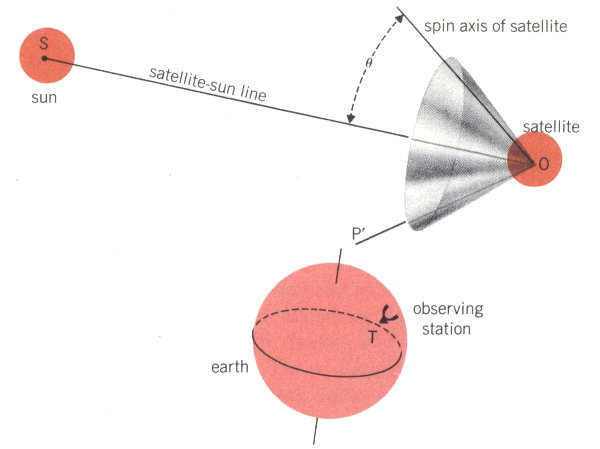
1. Solar aspect cells on the satellite report via telemetry the amount of sunlight they receive; from these data we can calculate the angle θ between the satellite’s spin axis, OP, and the satellite-sun line, OS. This means that OP can be anywhere on the surface of cone OPP′.
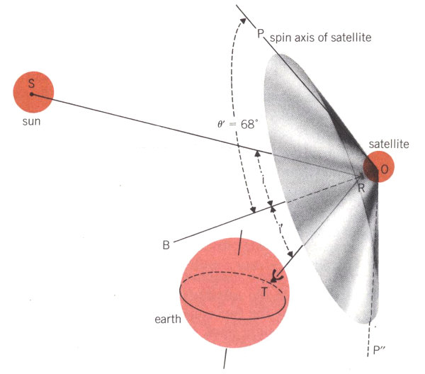
2. When sunlight is reflected to observing station T on the earth, we know that the angle of incidence i must be equal to the angle of reflection i′, and, if ORB is a line perpendicular to the reflector R, we know that the sun, the observer, and line ORB must all lie in one plane. Since we also know the position of the satellite in its orbit and the distance from it to the earth, we can locate line ORB precisely. The reflector R is set at an angle θ′ of 68° from the spin axis OP. This tells us that the spin axis must lie on the cone OPP″, which is now precisely determined by its axis ORB and its vertex angle 2θ′, equal to 136°.
56
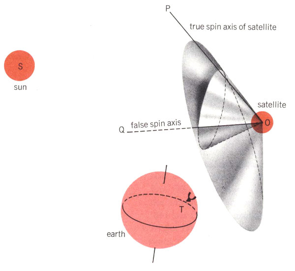
3. Cones OPP′ and OPP″ intersect along the two lines OP and OQ, so these are the only possible spin axis locations. From our general knowledge of the situation (or from any third measurement of glint time), OQ can be ruled out, and we conclude that only OP can be the true spin axis.
In Diagram 3 we have combined our two measurements of the satellite’s spin axis. You can see that the two cones will intersect along two straight lines, OP and OQ; these are thus the only possible positions that will satisfy both our measurements. Actually, of course, only one of these lines is the true location of the spin axis. And it is usually obvious which one it is, when we consider all our other data about the satellite’s position.
Using this technique, if we measure the exact times when we see flashes of reflected sunlight from Telstar, we can combine that information with data from our six solar aspect cells and get a good plot of the position of the satellite’s spin axis.
In theory, this looked like a very promising idea. But finding a satisfactory way to put it into practice was something else again. Our first thought was simply to make use of the light reflected from the sapphire covers on the satellite’s solar cells. However, these covers have a low coefficient of reflection and do not form a completely flat surface. This means that the light reflected from them is very much reduced in intensity and spreads out too much to give us the precise readings we want. On the other hand, if we attached a plane mirror with a high reflection coefficient to the satellite, we thought we could 57 pick up the minute flashes of reflected light from a distance of as much as a few thousand miles. So we decided to press ahead with this scheme and install one or more reflectors on the satellite.
By the time we started work on the mirrors, the final design of Telstar I was almost complete; this meant that we had to squeeze our mirrors aboard it as best we could. The most stringent physical requirement in designing them was weight; they could not add more than half a pound to Telstar’s total load. Nor could they project more than one-eighth inch from the satellite’s surface, or they might interfere with the radiation pattern for the main antenna. We also decided to make the mirrors out of highly polished metal, since any other possible material might break too easily. And the mirrors had to be as flat as possible, so the beam of reflected sunlight would not diverge by more than one degree.
Thus we had to design mirrors that would be very thin, very shiny, very flat, very light, and almost unbreakable. After much experimenting, we solved this rather tricky problem. The mirrors we added onto Telstar I, as you can see in the illustration below, were machined from aluminum alloy sheet, carefully polished by hand with abrasive papers, and buffed on a cloth wheel. Finally, we evaporated a thin layer of pure aluminum onto their surfaces to improve their reflection coefficients and make them resistant to corrosion. The three mirrors were fastened to the surface of the satellite with small screws, which had to be tightened and shimmed very carefully so that the mirrors stayed as flat as possible.
Locating the Mirrors on the Satellite
As we mentioned above, the flash angle θ′ between the satellite’s spin axis and a line perpendicular to the mirror is very important in our calculations. We made detailed studies of the various flash angles that would be possible during the first 60 days after launch. We plotted the times when the satellite would be above the horizon while our Crawford’s Hill, New Jersey, observing station was in darkness, and we made allowance for satellite orbits that might deviate slightly from the planned one. These calculations told us that the best flash angle for the mirror would be 68 degrees—which is the angle made by the first facets above Telstar’s equatorial antenna band. So we located a flat mirror on one of these facets. Because one of the solar aspect cells was already installed in the center of this facet, we were forced to cut a circular hole out of the center of the mirror.
But we knew that one mirror could not do the whole job. After Telstar I had been in orbit more than 30 days, the 68-degree mirror would only be in position to give infrequent flashes, and one at about 95 degrees would be more useful. This presented two problems. First, no facet on the satellite makes a 95-degree angle with the spin axis. However, we could use one of the facets just below the equatorial antenna, which makes a 112-degree angle, and groove or facet the mirror so that its reflecting faces became narrow strips slanted 17 degrees away from the base at the angle of 95 degrees (112 - 17 = 95). Our second problem was space—since there was not enough room left on any of the 112-degree facets to mount a second large mirror, we substituted two smaller mirrors and mounted them 120 degrees apart. This arrangement lets us know from which mirror we see flashes—the plane mirror gives one flash for each revolution of the satellite; the faceted mirrors give two flashes for each revolution of the satellite.
58
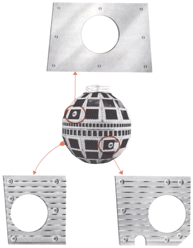
Sketches of three reflecting mirrors and their locations on the Telstar satellite. The upper plane mirror is set at 68° to the spin axis; the lower ones are faceted to give reflecting surfaces at 95°. Two of the satellite’s six solar aspect cells can be seen within the circular cut-outs in the mirrors.
59
How We Record Flashes from the Mirrors
Now we had finally found a satisfactory way to reflect a train of tiny flashes—much too faint to be seen by the naked eye—from Telstar as it passed across the sky during the night. But our main aim was to record the exact times when these flash bursts occurred. With this information, we could, using the method we described above, tell very accurately both the satellite’s spin axis and its rate of spin. We do not have space to describe the many problems that had to be solved in setting up the equipment to record the flashes. Let us merely outline the procedure that we finally devised:
1. To pick up the satellite’s flashes we use a 12-inch-aperture photoelectric telescope mounted on a radar trailer (shown in illustration below). It is pointed by means of prediction drive tapes produced by an electronic computer; these are based on data from previous passes.
2. On clear, dark nights when the satellite is at relatively short range, we can see it with an auxiliary finder telescope, and then adjust the large telescope precisely. Or, if the satellite’s high-frequency beacon has been turned on, the Holmdel microwave antenna can automatically point our large telescope.
3. When flashes of light are picked up by the telescope, they fall directly onto the cathode of a photomultiplier tube. They are then filtered out from the random light in the night sky and amplified.
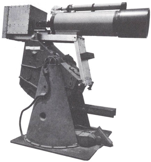
Twelve-inch telescope and electronics box mounted on a radar antenna pedestal at Crawford’s Hill. Three-inch sighting telescope mounted on top has since been replaced by six-inch telescope.
4. Rather than make a continuous recording of the output—one night this would have produced a record twelve miles long for us to pore over—we use an electronic trigger. This is the time base of an oscilloscope, whose sawtooth output is set in operation only if a signal of four volts or more is received (photo below).
60
5. A pen recorder makes a continuous line on a revolving drum, with a heated stylus connected to a galvanometer marking a permanent record on heat-sensitive paper. Any signal output from the oscilloscope is picked up by the galvanometer and causes the pen to make a sawtoothed mark; when the paper is unrolled from the drum, these marks are clearly visible as notches in a series of otherwise straight lines.
6. A synchronous timer marks the chart every ten seconds, and we are able to time individual pulses with a precision of one tenth of a second. Because the beginning and end of a train of pulses are not always distinct, we can only determine the center of a burst of flashes—which we use as our most important time indication—to within two seconds. However, this is accurate enough, for a change of only one degree in the orientation of the satellite’s spin axis would change the time of the flash burst center by about half a minute (see below).
7. We use a second oscilloscope to check on whether the signals we receive are genuine flashes or just accidental stray light. This oscilloscope has a long-persistence screen, which we use as a temporary memory. The pulses traced on its cathode ray tube are automatically photographed by a 35-mm camera while they persist on the screen. We can then examine the photograph to see if the pulses are genuine, which we ascertain from (a) their shape and size and (b) the intervals between successive pulses. Looking at the photographic record also confirms whether we are observing flashes from the 68° plane mirror or the 95° faceted mirrors. We can calculate the satellite’s spin rate by measuring the intervals between individual flashes.
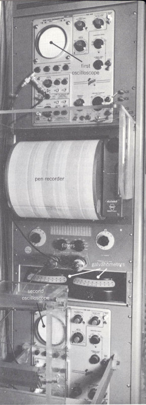
General view of amplifying, monitoring, and recording gear that picks up glints of sunlight at the Crawford’s Hill observation station.
61
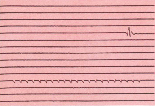
Enlarged portion of a typical pen record of flashes of sunlight from Telstar mirrors, showing a burst of 21 glints from the 68° mirror recorded at 03:40:58 Greenwich Mean Time on August 9, 1962. Synchronizing vibration mark seven lines above the recorded burst indicates the time 02:59:00. Measuring the horizontal distance between consecutive sawtooth marks tells us that the spin rate is between 163 and 164 revolutions per minute. (Precise measurements of the oscilloscope traces fixed the exact spin rate at the time of this burst at 163.64 revolutions per minute.)
Results
Telstar I was launched on July 10, 1962. That evening, beginning on the satellite’s seventh pass, we were able to detect trains of flashes from the mirrors. We assumed that, since Telstar had been launched almost exactly according to plan, its spin axis would be perpendicular to the plane of the earth’s orbit, and we calculated when we should see the flashes. And, each time, we actually saw them within two minutes of the times we had predicted—so we knew that the spin axis was almost exactly where it should be.
Our measurements have continued whenever the weather and other conditions permitted. Combining readings from the bursts of flashes and telemetry data from the solar aspect cells, we have accurately plotted Telstar’s spin axis; it has continued to precess very much as we predicted it would. We have also seen what happens to the spin axis when the satellite’s torque coil is turned on. And, by measuring the intervals between flashes, we have made very precise measurements of the spin rate, which is gradually decreasing mostly according to schedule. However, the plot is showing some small unexplained variations of spin decay rate, and a study of them will, we hope, throw light on some of the variations of the earth’s magnetic field.
For future communications work, particularly with satellites at longer ranges, it would seem to be preferable to use stiffer, flatter mirrors and to make them from beryllium rather than aluminum alloy. More accurate tracking means, more observatory sites, and more powerful telescopes will also be needed. But for this first experimental use our little mirrors have worked very well.
Jeofry S. Courtney-Pratt was born in Hobart, Tasmania, Australia, and received a Bachelor of Engineering degree from the University of Tasmania in 1942 and a Ph.D. from Cambridge University in 1949. He was also awarded an Sc.D. by Cambridge in 1958. He joined Bell Telephone Laboratories in 1958, and has done research in high-speed photography, optics, optical masers, the properties of materials, and the physics of the contact of solids.
62