The Lewis Automatic Machine Gun.
Reading edition
LIST OF PARTS.
1.
Butt plate.
2.
Butt plate screws (2).
3.
Buttstock.
4.
Butt tang screw.
5.
Butt tang.
7.
Butt latch.
8.
Back sight bed spring.
9.
Back sight bed spring screw.
10.
Butt latch spring.
11.
Back sight bed.
13.
Feed cover.
14.
Back sight leaf.
20.
Back sight slide.
21.
Ejector.
22.
Guard side pieces (2).
23.
Back sight axis pin washer.
24.
Back sight axis pin.
26.
Receiver.
27.
Magazine pawls spring.
28.
Stop pawl.
29.
Rebound pawl.
30.
Trigger.
31.
Feed operating stud.
32.
Safety (right and left).
33.
Trigger pin.
34.
Feed operating arm.
35.
Feed pawl.
36.
Feed pawl spring.
37.
Bolt.
38.
Charging handle.
39.
Guard.
40.
Cartridge guide spring.
41.
Sear spring.
42.
Sear spring box.
43.
Magazine pan.
44.
Ejector cover.
45.
Extractors (2).
46.
Gear stop.
47.
Striker fixing pin.
48.
Gear stop pin.
49.
Gear stop spring.
50.
Striker.
51.
Cartridge spacer ring.
52.
Gear.
53.
Mainspring casing.
54.
Magazine top plate rivets (6).
55.
Mainspring.
56.
Collet pin.
57.
Mainspring collet.
58.
Magazine centre.
59.
Mainspring rivets (2).
60.
Magazine latch spring.
61.
Gear casing.
62.
Magazine latch.
63.
Centre key.
65.
Gear case hinge pin.
66.
Feed operating arm latch.
67.
Magazine top plate.
68.
Receiver lock pin.
69.
Spacer ring rivets (5).
70.
Interior separators (25).
71.
Radiator casing rear, locking piece.
72.
Rack.
74.
Radiator casing rear.
75.
Piston connecting pin.
76.
Barrel.
77.
Gas cylinder.
78.
Radiator.
79.
Piston.
80.
Regulator key stud.
81.
Gas regulator key.
82.
Gas chamber.
83.
Gas chamber band.
84.
Gas regulator cup.
85.
Clamp ring.
86.
Front sight.
87.
Clamp ring positioning screw.
88.
Clamp ring screw.
89.
Barrel mouthpiece.
90.
Radiator casing front.
91.
Sear (rear).
92.
Hand grip.
93.
Oil well.
94.
Oil well cap.
95.
Oil brush.
96.
Spade grip butt tang.
97.
Deflector.
98.
Deflector arm.
99.
Deflector arm joint pin.
100.
Deflector clip.
101.
Deflector clip joint pin.
102.
Deflector bracket.
103.
Deflector clamp screw.
104.
Deflector latch.
105.
Deflector latch screw.
106.
Deflector clamp screw washer.
107.
Deflector clamp screw stop nut.
108.
Shell catcher bag.
109.
Mounting yoke.
110.
Mounting yoke clamp.
111.
Mounting yoke bronze pillar.
112.
Mounting yoke pillar screw.
113.
Mounting yoke clamp hinge pin.
114.
Mounting yoke clamp pin.
115.
Mounting yoke clamp key.
116.
Back sight elevating screw.
117.
Back sight elevating screw head.
118.
Back sight elevating screw head pin.
119.
Back sight elevating screw head spring.
120.
Sear pin.
121.
Butt latch pin.
122.
Mounting yoke pillar hinge pin.
123.
Mounting yoke chain.
124.
Mounting standard.
125.
Light field mount bottom cross brace.
126.
Light field mount centre post.
127.
Light field mount feet (2).
128.
Light field mount front legs (2).
129.
Light field mount front yoke.
130.
Light field mount knuckle joint.
131.
Light field mount knuckle joint pin.
132.
Light field mount rear brace.
133.
Light field mount T joint, centre.
134.
Light field mount T joint, side (2).
135.
Light field mount top lug.
136.
Barrel mouthpiece spanner.
137.
Magazine filling handle.
44
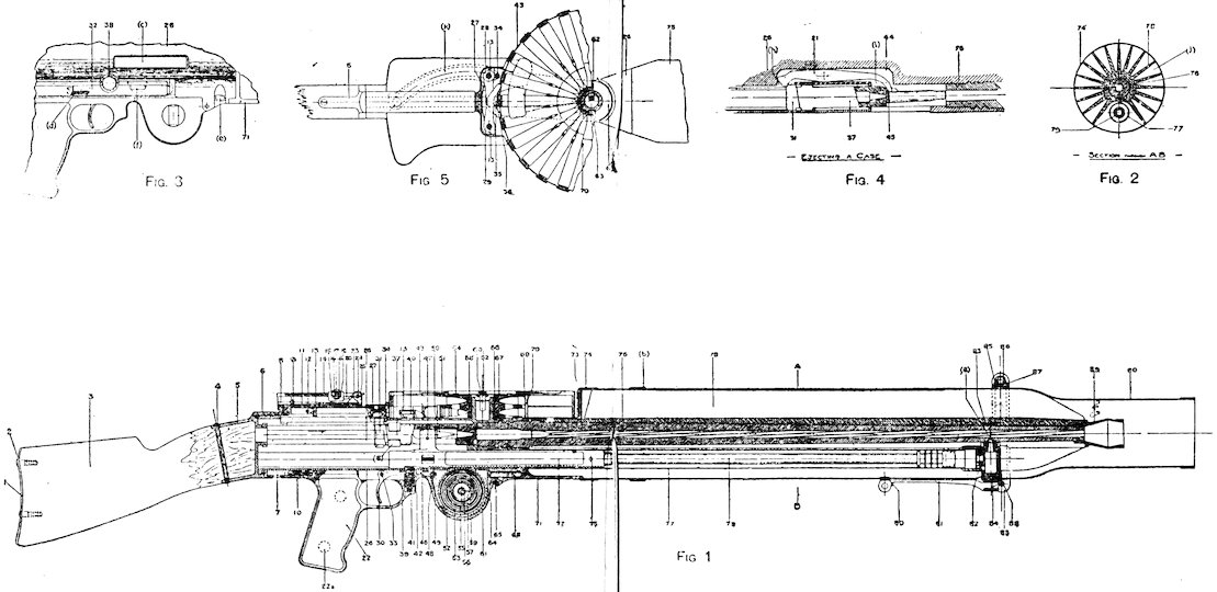
Plate VI. LEWIS AUTOMATIC MACHINE GUN.
47
Description.
The gun complete weighs 25¼ lbs. and can be withdrawn from its leather case and put into action immediately.
There are only 62 parts in the gun proper—these cannot be wrongly assembled, and require no adjustment.
No water is used for cooling purposes, the steel barrel being closely fitted with a jacket of aluminium having deeply-cut grooves throughout its length. Over this is a thin tubular steel casing, the muzzle end of which extends (in reduced diameter) beyond the end of barrel, the special shaped mouthpiece screwed to the end of barrel serving the double purpose of firmly securing the radiator in place and of directing the powder blast of each discharge as to greatly increase the “ejector action” of this blast in sucking cool air through the grooves of the radiator. The system is so effective that the gun is found to give a slightly greater velocity to the bullet than can be obtained from the same length of barrel in a shoulder arm firing the same ammunition. There is no excessive recoil and the gun can be used with or without mount.
The gun is fed from a rotating drum magazine, which is controlled by the reciprocating breech mechanism.
Shell Deflector.
The shell deflector is an attachment for controlling the ejection of empty cartridge cases. It is very readily and quickly attached, and when in position can be instantly swung back out of the way so that the inside of the gun may be examined or any part of the mechanism got at.
Light Folding Field Mount.
Is a three-and-a-half-pound folding mount adapted for general use with infantry and cavalry. The mount is surprisingly rigid, and permits of very accurate shooting. Both front and rear mounting yokes, connected through centre post and rear brace, are pivoted about the axis of the centre post, so that the gun is always free to traverse. The gun is also free to turn within the yokes, so that the sights may always be kept vertical, no matter what the position of the feet. When the mount is attached, it is often convenient to use the rear brace as a handle for carrying the gun.
48
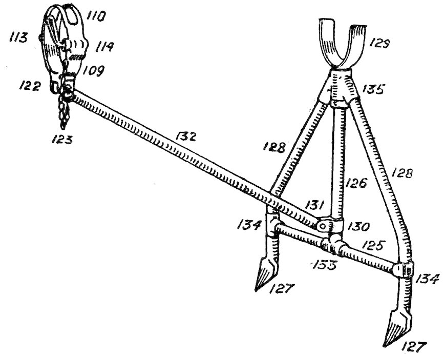
Plate VII. Light Folding Field Mount Complete.
49
To Put Gun into Action.
When a loaded magazine is dropped into place over the magazine post, and the charging handle pulled to the rear as far as it will go and then released, the gun is put into action by a pull on the trigger, and continues to fire until the finger pressure on the trigger is released, or until the magazine is empty.
Single Shots.
When the trigger is pulled once and very quickly released a single shot is fired, this may be repeated at will until the magazine is empty.
Semi-Automatic Fire.
Within the limits of the magazine capacity the gun continues to fire so long as the trigger is held back, and stops firing whenever the trigger is released.
Full Automatic Fire.
Continued pressure on the trigger results in full automatic fire, which need be interrupted only by the four seconds interval required to replace emptied magazines by loaded ones.
During firing, before the magazine has been emptied, the gun stops at the beginning of the forward stroke, in the “ready to feed” position.
In this position the action is open and the chamber empty, but firing can be resumed on pulling the trigger.
General Note.
Before Firing.—See to it that bore is clear, working parts properly lubricated, and that tension of main spring is sufficient to avoid missfires.
After Firing.—See that gun is immediately unloaded, and that bore, working parts, and bearing surfaces are carefully examined, cleaned, and properly lubricated as soon as possible.
It is especially important to oil piston head and inside of gas cylinder; and to remove oil, and replace gas regulator cup.
Burrs found raised on any working part should be removed, and any roughening on a bearing surface should be smoothed down with fine emery or an oilstone.
50
TO STRIP AND ASSEMBLE.
The gun may be taken apart starting with the mechanism in any position, but it is best, whenever practicable, to see that the magazine is removed, the chamber empty, and the charging handle at the extreme forward end of its stroke, before commencing to dissemble. If this procedure is followed there will be no need to readjust the mainspring tension or to make any other adjustment when the gun is reassembled.
Stripping.
To dissemble gun, insert point of a bullet into slot leading to butt latch and push forward against force of butt latch spring. At the same time twist buttstock up and to left, then remove by withdrawing it to the rear. This removes buttstock group which should not be further dissembled.
Next, hold back trigger and pull back guard until clear of receiver. This removes guard, which contains trigger mechanism and butt latch.
Pull down gear casing until it drops clear of rack.
Pull back charging handle until it reaches end of slot, then withdraw by pulling it out away from receiver.
Withdraw operating rod complete and bolt complete by pulling them both together to rear until clear of receiver.
With point of a bullet push back on receiver lock pin, then twist receiver up and to left and unscrew it from barrel.
The foregoing operations divide the gun into convenient groups.
DETAILED STRIPPING.
Buttstock Group.
It is best never to strip this group, but if found necessary, the screws securing buttplate and butt tang to buttstock are readily removed.
Receiver Group.
See that the feed operating arm is pushed to the right, then pull back and remove feed cover.
Feed Cover.—From the feed cover the stop pawl, rebound pawl and cartridge guide spring are readily removed with the point of a bullet.
51Back Sight.—The back sight may be stripped from feed cover by removing bed spring screw.
Feed Operating Arm.—Remove feed operating arm complete, by pushing forward on feed operating arm latch and then lifting clear of magazine post. The feed pawl and feed pawl spring are removed from feed operating arm by lifting them clear of the studs. The latch should not be removed.
Ejector.—With the point of a bullet lift and pull out ejector cover and the ejector.
Safety.—The safeties may be prised out of the receiver with a bullet point.
Gear case hinge pin and centre key are permanently assembled and should not be removed.
Gear Casing.—Push forward and remove receiver lock pin and unhook gear casing from gear case hinge pin.
Mainspring Group.
To strip completely the parts assembled in gear casing, raise the gear stop with the point of a bullet, and allow mainspring to unwind.
Gear.—Then unscrew the collet pin and shake out gear.
Mainspring.—Pushing with a bullet through the gear against mainspring collet forces out mainspring casing from which mainspring, with its locating rivets and mainspring collet, may also be removed by the use of a bullet.
Gear Stop.—The gear stop and gear stop spring should not be stripped, but in case of necessity they may be removed by driving out the gear stop pin.
Guard Group.
The assembled guard contains trigger mechanism and butt latch. To strip, punch out trigger pin and sear pin.
Trigger.—Pull back trigger and lift out.
Sear.—Remove sear, sear spring box and sear spring.
Butt Latch.—Punch out butt latch pin and remove butt latch, and butt latch spring.
In ordinary practice the guard group need never be stripped.
52
Bolt and Rod Group.
The bolt and rod group comprises the bolt complete and operating rod complete. These two assembled parts are withdrawn together from the receiver, and may then be separated by lifting bolt clear of operating post on rod.
Bolt Complete.
Feed Operating Stud.—Unscrew and remove feed operating stud from rear end of bolt.
Extractors.—The extractors are spring-tempered and are sprung into place. To remove, insert point of a bullet under extractor claw and push head of extractor out and away from bolt. At the same time draw the whole extractor forward until it is clear of its seating.
Operating Rod Complete.
Not usually stripped.
Piston.—The piston connecting pin is riveted in place, but may readily be punched out in case it is desired to remove piston.
Striker.—The striker may be withdrawn after punching out striker fixing pin.
Barrel Group.
Gas Regulator.—Lift out gas regulator key, then unscrew and remove gas regulator cup.
Clamp Ring.—Using the gas regulator key as a tool, unscrew clamp ring screw and remove clamp ring which carries front sight and clamp ring positioning screw.
Radiator Casing.—Pull forward radiator casing front, and pull back radiator casing rear which is permanently assembled to radiator casing rear locking piece.
Gas Cylinder.—Unscrew and remove gas cylinder, using operating rod as a wrench.
Gas Chamber.—Unscrew gas chamber, using, if necessary, barrel mouthpiece wrench.
Barrel Mouthpiece.—Unscrew barrel mouthpiece. Thread is left-handed.
Barrel.—Drive out barrel from radiator. This operation may conveniently be accomplished before removing barrel mouthpiece by unscrewing latter part way and then allowing barrel and radiator to drop from a height of two 53or three feet on to a solid piece of wood, striking on front end of barrel mouthpiece. The weight of the radiator dropping from this height will usually loosen barrel sufficiently so that it can be withdrawn by hand from radiator after mouthpiece has been removed.
Gas Chamber Band.—Lift out gas chamber band from its recess in radiator.
Assembling.
By reversing the operations for stripping the assembling of gun is readily and quickly carried out. The following points, however, should be noted:—
1. Be sure that gas chamber band is correctly inserted into its place in the radiator before barrel is pushed home, and that barrel is turned with gas port at bottom.
2. In replacing bolt and operating rod the cam slot in bolt is slipped over striker and feed operating stud is screwed into bolt as far as it will go.
3. After inserting bolt, rod, and charging handle, the charging handle is carried forward to extreme end of its stroke before gear casing is swung up into place and rack engaged.
4. The mainspring is wound up by engaging the rack and gear, disengaging the guard, and pulling back on the charging handle until the required tension is obtained. The gear is then disengaged, charging handle moved completely forward, gear re-engaged and guard pushed home.
5. To reduce tension of mainspring proceed as follows:—
Remove buttstock.
Disengage both guard and gear.
Move charging handle part way back.
Re-engage gear and guard.
Replace buttstock.
STOPPAGES.
Position of C.H. Immediate action. Remedy. Cause.
Forward:—
(a) Turn magazine free and change Magazine empty.
(b) If magazine is fixed, pull back C.H. Missfire or space or rotation not sufficient.
54(c) If recur, change magazine Examine rim of old magazine Faulty feed due to damaged rim.
Feed arm pawl. Stop pawls Feed arm pawl, or stop pawl.
(d) If missfire on pressing trigger examine return spring If too light—adjust. Weak or broken return spring.
If broken—substitute Damaged or broken striker.
If correct—change rod
(e) If C.H. will not come back pull back with wooden handle If dirty—clean Dirt.
If hot—cool
C.H. back slightly Pull C.H. back with wooden handle or pull through Bulged cartridge (should never get into magazine.)
Separated case (unknown as yet).
C.H. nearly back Examine ejection opening, if clear pull C.H. back and carry on
or, back to full extent If return spring is weak, adjust or change it Clean gas cylinder, or piston rod and oil up Weak or broken return spring.
If it recurs, remove magazine and gas regulator and fire. After firing put back gas regulator, with large hole to rear Friction in gas cylinder or moving parts.
If empty case is found, pull crank handle, raise safety catch, remove magazine and empty. Examine rim If recurs, examine extractor ejector Weak or broken extractors.
Broken ejector.
If crank handle jams remove magazine Magazine not really home, or rim injured, or catch broken.
If crank handle flies forward, insert new magazine, otherwise examine cartridge guide spring Change if broken Weak or broken cartridge guide spring.
55