Chapter LXVII · MANAGEMENT
Reading edition
The term "management," broadly speaking, includes not only the actual skilled attention necessary for the proper operation of the machines, after the plant is built, but also other duties which must be performed from its inception to completion, and which may be classified as
1. Selection; 2. Location; 3. Erection; 4. Testing; 5. Running; 6. Care; 7. Repair.
That is to say, someone must select the machinery, determine where each machine is to be located, install them, and then attend to the running of the machines and make any necessary repairs due to the ordinary mishaps likely to occur in operation.
These various duties are usually entrusted to more than one individual; thus, the selection and location of the machinery is done by the designer of the plant, and requires for its proper execution the services of an electrical engineer, or one possessing more than simply a practical knowledge of power plants.
The erection of the machines is best accomplished by those making a specialty of this line of work, who by the nature of the undertaking acquire proficiency in methods of precision and an appreciation of the value of accuracy which is so essential in the work of aligning the machines, and which if poorly done will prove a constant source of annoyance afterward.
The attention required for the operation of the machines, embracing the running care and repair, is left to the "man in charge," who in most cases of small and medium size plants is the chief steam engineer. He must therefore, not only understand the steam apparatus, but possess sufficient knowledge of electrical machinery to operate and maintain it in proper working order.
The present chapter deals chiefly with alternating current machinery, the management of direct current machines having been fully explained in Guide No. 3, however, some of the matter here presented is common to both classes of apparatus.
Selection.—In order to intelligently select a machine so that it will properly harmonize with the conditions under which it is to operate, there are several things to be considered.
1. Type; 2. Capacity; 3. Efficiency; 4. Construction.
The general type of machine to be used is, of course, dependent on the system employed, that is, whether it be direct or alternating, single or polyphase.
Thus, the voltage in most cases is fixed except on transformer systems where a choice of voltage may be had by selecting a transformer to suit.
In alternating current constant pressure transmission circuits, an average voltage of 2,200 volts with step down transformer ratios of 1⁄10 and 1⁄20 is in general use, and is recommended.
For long distance, the following average voltages are recommended 6,000; 11,000; 22,000; 33,000; 44,000; 66,000; 88,000; and higher, depending on the length of the line and degree of economy desired.
In alternating circuits the standard frequencies are 25, and 60 cycles. These frequencies are already in extensive use and it is recommended to adhere to them as closely as possible.
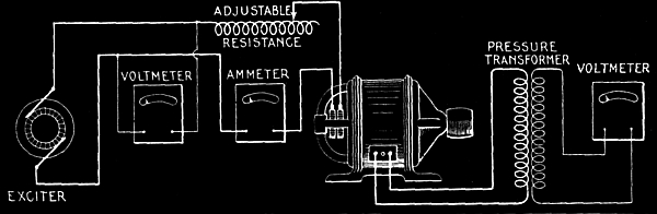
Fig. 2,784.—Diagram of connections for testing to obtain the saturation curve of an alternator. The saturation curve shows the relation between the volts generated in the armature and the amperes of field current (or ampere turns of the field) for a constant armature current. The armature current may be zero, in which case the curve is called no load saturation curve, or sometimes the open circuit characteristic curve. A saturation curve may be taken with full load current in the armature; but this is rarely done, except in alternators of comparatively small output. If a full load saturation curve be desired, it can be approximately calculated from the no load saturation curve. The figure shows the connections. If the voltage generated is greater than the capacity of the voltmeter, a multiplying coil or a step down pressure transformer may be used, as shown. A series of observations of the voltage between the terminals of one of the phases, is made for different values of the field current. Eight or nine points along the curve are usually sufficient, the series extending from zero to about fifty per cent. above normal rated voltage. The points should be taken more closely together in the vicinity of normal voltage than at other portions of the curve. Care must be taken that the alternator is run at its rated speed, and this speed must be kept constant. Deviations from constant speed may be most easily detected by the use of a tachometer. If the machine be two phase or three phase, the voltmeter may be connected to any one phase throughout a complete series of observations. The voltage of all the phases should be observed for normal full load excitation by connecting the voltmeter to each phase successively, keeping the field current constant at normal voltage. This is done in order to see how closely the voltage of the different phases agree.
In fixing the capacity of a machine, careful consideration should be given to the conditions of operation both present and future in order that the resultant efficiency may be maximum.
Most machines show the best efficiency at or near full load. If the load be always constant, as for instance, a pump forcing water to a given head, it would be a simple matter to specify the proper size of machine, but in nearly all cases, and especially in electrical plants, the load varies widely, not only the daily and hourly fluctuations, but the varying demands depending on the season of the year and growth of the plant's business. All of these conditions tend to complicate the matter, so that intelligent selection of capacity of a machine requires not only calculation but mature judgment, which is only obtained by long experience.
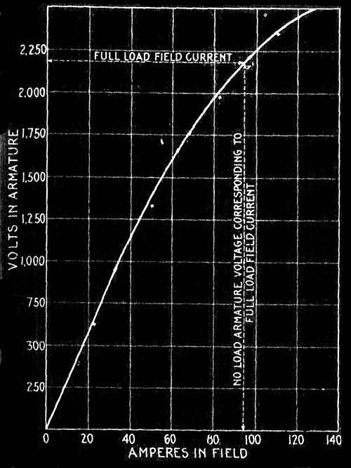
Fig. 2,785.—Saturation curve taken from a 2,000 kw., three phase alternator of the revolving field type, having 16 poles, and generating 2,000 volts, and 576 amperes per phase when run at 300 R.P.M.
In selecting a machine, or in fact any item connected with the plant its construction should be carefully considered.
Standard construction should be insisted upon so that in the event of damage a new part can be obtained with the least possible delay.
The parts of most machines are interchangeable, that is to say, with the refined methods of machinery a duplicate part (usually carried in stock) may be obtained at once to replace a defective or broken part, and made with such precision that little or no fitting will be required.
The importance of standard construction cannot be better illustrated than in the matter of steam piping, that is, the kind of fittings selected for a given installation.
With the exception of the exhaust line from engine to condenser, where other than standard construction may sometimes be used to reduce the frictional resistance to the steam, the author would adhere to standard construction except in very exceptional cases. Those who have had practical experience in pipe fitting will appreciate the wisdom of this.
For installations in places remote from large supply houses, the more usual forms of standard fittings should be employed, such as ordinary T's, 45° and 90° elbows, etc.
In such locations, where designers specify the less usual forms of standard fittings such as union fittings, offset reducers, etc., or special fittings made to sketch, it simply means, in the first instance that they usually cannot be obtained of the local dealer, making it necessary to order from some large supply house and resulting in vexatious delays.
As a rule, those who specify special fittings have found that their making requires an unreasonable length of time, and the cost to be several times that of the equivalent in standard fittings.
An examination of a few installations will usually show numerous special and odd shape fittings, which are entirely unnecessary.
Moreover, a standard design, in general, is better than a special design, because the former has been tried out, and any imperfection or weakness remedied, and where thousands of castings of a kind are turned out, a better article is usually the result as compared with a special casting.
In the matter of construction, in addition to the items just mentioned, it should be considered with respect to
1. Quality; 2. Range; 3. Accessibility; 4. Proportion; 5. Lubrication; 6. Adjustment.
It is poor policy, excepting in very rare instances, to buy a "cheap" article, as, especially in these days of commercial greed, the best is none too good.
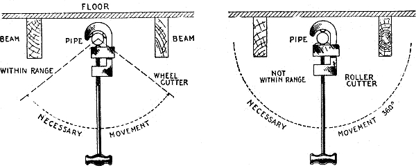
Figs. 2,786 and 2,787.—Wheel and roller pipe cutters illustrating range. The illustrations show the comparative movements necessary with the two types of cutter to perform their function. The wheel cutter requiring only a small arc of movement will cut a pipe in an inaccessible place as shown, which with a roller cutter would be impossible. Accordingly, the wheel cutter is said to have a greater range than the roller cutter.
Perhaps next in importance to quality, at least in most cases, is range. This may be defined as scope of operation, effectiveness, or adaptability. The importance of range is perhaps most pronounced in the selection of tools, especially for plants remote from repair shops.
For instance, in selecting a pipe cutter, there are two general classes: wheel cutters, and roller cutters. A wheel cutter has three wheels and a roller cutter one wheel and two rollers, the object of the rollers being to keep the wheel perpendicular to the pipe in starting the cut and to reduce burning. It must be evident that in operation, a roller cutter requires sufficient room around the pipe to permit making a complete revolution of the cutter, whereas, with a wheel cutter, the work may be done by moving the cutter back and forth through a small arc, as illustrated in figs. 2,786 and 2,787. Thus a wheel cutter has a greater range than a roll cutter.
Range relates not only to ability to operate in inaccessible places but to the various operations that may be performed by one tool.
PROPERTIES OF STANDARD WROUGHT IRON PIPE
Diameter. Thick- ness. Circumference. Transverse areas.
Nominal internal. Actual external. Actual internal. External. Internal. External. Internal. Metal.
Inches Inches Inches Inches Inches Inches Sq. ins. Sq. ins. Sq. ins.
⅛ .405 .27 .068 1.272 .848 .129 .0573 .0717
¼ .54 .364 .088 1.696 1.144 .229 .1041 .1249
⅜ .675 .494 .091 2.121 1.552 .358 .1917 .1663
½ .84 .623 .109 2.639 1.957 .554 .3048 .2492
¾ 1.05 .824 .113 3.299 2.589 .866 .5333 .3327
1 1.315 1.048 .134 4.131 3.292 1.358 .8626 .4954
1¼ 1.66 1.38 .14 5.215 4.335 2.164 1.496 .668
1½ 1.9 1.611 .145 5.969 5.061 2.835 2.038 .797
2 2.375 2.067 .154 7.461 6.494 4.43 3.356 1.074
2½ 2.875 2.468 .204 9.032 7.753 6.492 4.784 1.708
3 3.5 3.067 .217 10.996 9.636 9.621 7.388 2.243
3½ 4. 3.548 .226 12.566 11.146 12.566 9.887 2.679
4 4.5 4.026 .237 14.137 12.648 15.904 12.73 3.174
4½ 5. 4.508 .246 15.708 14.162 19.635 15.961 3.674
5 5.563 5.045 .259 17.477 15.849 24.306 19.99 4.316
6 6.625 6.065 .28 20.813 19.054 34.472 28.888 5.584
7 7.625 7.023 .301 23.955 22.063 45.664 38.738 6.926
8 8.625 7.982 .322 27.096 25.076 58.426 50.04 8.386
9 9.625 8.937 .344 30.238 28.076 72.76 62.73 10.03
10 10.75 10.019 .366 33.772 31.477 90.763 78.839 11.924
11 12. 11.25 .375 37.699 35.343 113.098 99.402 13.696
12 12.75 12. .375 40.055 37.7 127.677 113.098 14.579
PROPERTIES OF STANDARD WROUGHT IRON PIPE
(Continued)
Diam. Length of pipe per square foot of Length of pipe per containing one cubic foot. Nominal weight per foot. Number of threads per inch.
Nominal internal. External surface Internal surface
Inches Feet. Feet. Feet. Pounds.
⅛ 9.44 14.15 2513. .241 27
¼ 7.075 10.49 1383.3 .42 18
⅜ 5.657 7.73 751.2 .559 18
½ 4.547 6.13 472.4 .837 14
¾ 3.637 4.635 270. 1.115 14
1 2.904 3.645 166.9 1.668 11½
1¼ 2.301 2.768 96.25 2.244 11½
1½ 2.01 2.371 70.66 2.678 11½
2 1.608 1.848 42.91 3.609 11½
2½ 1.328 1.547 30.1 5.739 8
3 1.091 1.245 19.5 7.536 8
3½ .955 1.077 14.57 9.001 8
4 .849 .949 11.31 10.665 8
4½ .764 .848 9.02 12.34 8
5 .687 .757 7.2 14.502 8
6 .577 .63 4.98 18.762 8
7 .501 .544 3.72 23.271 8
8 .443 .478 2.88 28.177 8
9 .397 .427 2.29 33.701 8
10 .355 .382 1.82 40.065 8
11 .318 .339 1.450 45.95 8
12 .299 .319 1.27 48.985 8
Open construction should be employed, wherever possible, so that all parts of a machine that require attention, or that may become deranged in operation, may be accessible for adjustment or repair.
The design should be such that there is ample strength, and the bearings for moving parts should be of liberal proportions to avoid heating with minimum attention.
A comparison of the proportions used by different manufacturers for a machine of given size might profitably be made before a selection is made.
The matter of lubrication is important.
Fast running machines, such as generators and motors, should be provided with ring oilers and oil reservoirs of ample capacity, as shown in figs. 2,788 to 2,794.
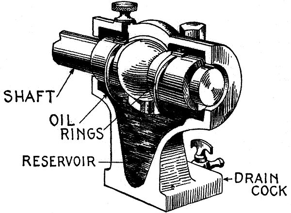
Fig. 2,788.—Sectional view showing a ring oiler or self oiling bearing. As shown the pedestal or bearing standard is cored out to form a reservoir for the oil. The rings are in rolling contact with the shaft, and dip at their lower part into the oil. In operation, oil is brought up by the rings which revolve because of the frictional contacts with the shaft. The oil is in this way brought up to the top of the bearing and distributed along the shaft gradually descending by gravity to the reservoir, being thus used over and over. A drain cock, is provided in the base so that the oil may be periodically removed from the reservoir and strained to remove the accumulation of foreign matter. This should be frequently done to minimize the wear of the bearing.
All bearings subject to appreciable wear should be made adjustable so that lost motion may be taken up from time to time and thus keep the vibration and noise of operation within proper limits.
Selection of Generators.—This is governed by the class of work to be done and by certain local conditions which are liable to vary considerably for different stations.
These variable factors determine whether the generators must be of the direct or alternating current type, whether they must be wound to develop a high or a low voltage, and whether their outputs in amperes must be large or small. Sufficient information has already been given to cover these various cases; there are, however, certain general rules that may advantageously be observed in the selection of generators designed to fill any of the aforementioned conditions, and it is well to possess certain facts regarding their construction.
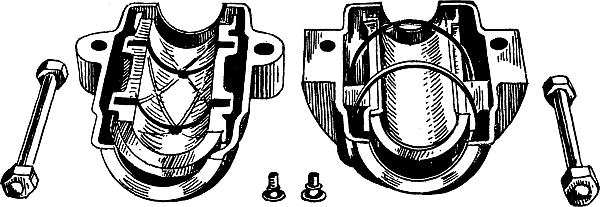
Figs. 2,789 to 2,794.—Self oiling self aligning bearing open. Views showing oil grooves, rings, bolts etc.
Ques. Name an important point to be considered in selecting a generator.
Ans. Its efficiency.
Ques. What are the important points with respect to efficiency?
Ans. A generator possessing a high efficiency at the average load is more desirable than a generator showing a high efficiency at full load.
Ques. Why?
Ans. The reason is that in station practice the full load limit is seldom reached, the usual load carried by a generator ordinarily lying between the one-half and three-quarter load points.
Ques. How do the efficiencies of large and small generators compare?
Ans. There is little difference.
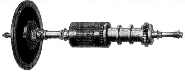
Fig. 2,795.—Rotor of Westinghouse type T turbine dynamo set. The dynamo is of the commutating pole type either shunt or compound wound. The turbine is of the single wheel impulse type. The wheel is mounted directly on the end of the shaft as shown. Steam is used two or more times on the wheel to secure efficiency. A fly ball governor is provided with weights hung on hardened steel knife edges. In case of over speeding, an automatic safety stop throttle valve is tapped shutting off the steam supply. This type of turbine dynamo set is especially applicable for exciter service in modern, superheated steam generating stations where the steam pressure exceeds 125 pounds. Westinghouse Type T turbines operate directly (that is, without a reducing valve) on pressures up to 200 pounds per square inch with steam superheated to 150 degrees Fahrenheit.
Ques. How are the sizes and number of generator determined?
Ans. The sizes and number of generator to be installed should be such as to permit the engines operating them being worked at nearly full load, because the efficiencies of the latter machines decrease rapidly when carrying less than this amount.
Ques. What is understood by regulation?
Ans. The accuracy and reliability with which the pressure or current developed in a machine may be controlled.
It is generally possible if purchasing of a reputable concern, to obtain access to record sheets on which may be found results of tests conducted on the generator in question, and as these are really the only means of ascertaining the values of efficiency and regulation, the purchaser has a right to inspect them. If, for some reason or other, he has not been afforded this privilege, he should order the machine installed in the station on approval, and test its efficiency and regulation before making the purchase.
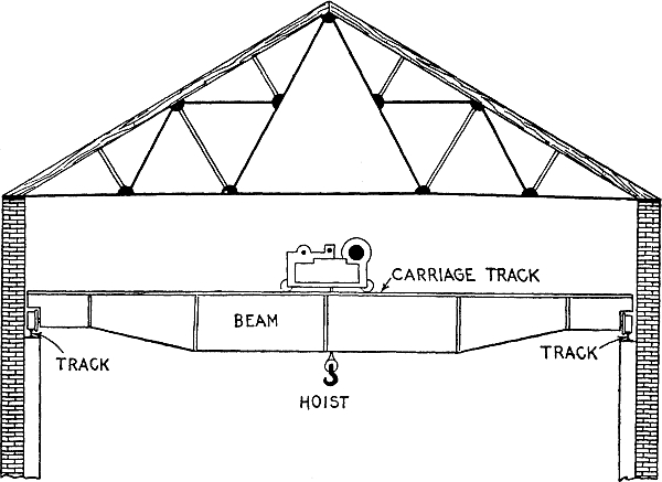
Fig. 2,796.—Cross section of electrical station showing small traveling crane.
Installation.—The installation of machines and apparatus in an electrical station is a task which increases in difficulty with the size of the plant. When the parts are small and comparatively light they may readily be placed in position, either by hand, by erecting temporary supports which may be moved from place to place as desired, or by rolling the parts along on the floor upon pieces of iron pipe. If, however, the parts be large and heavy, a traveling crane such as shown in fig. 2,797, becomes necessary.
Ques. What precaution should be taken in moving the parts of machines?
Ans. Care should be taken not to injure the bearings and shafts, the joints in magnetic circuits such as those between frame and pole pieces, and the windings on the field and armature.
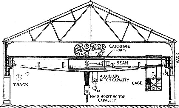
Fig. 2,797.—Cross section of electrical station showing a traveling crane for the installation or removal of large and heavy machine parts. A traveling crane consists of an iron beam which, being supplied with wheels at the ends, can be made to move either mechanically or electrically upon a track running the entire length of the station. This track is not supported by the walls of the building, but rests upon beams specially provided for the purpose. In addition to the horizontal motion thus obtained, another horizontal motion at right angles to the former is afforded by means of the carriage which, being also mounted on wheels, runs upon a track on the top of the beam. Electrical power is generally used to move the carriage and also the revolving drums contained thereon, the latter of which give a vertical motion to the main hoist or the auxiliary hoist, these hoists being used respectively for raising or lowering heavy or light loads. In the larger sizes of electric traveling crane, a cage is attached to the beam for the operator, who, by means of three controllers mounted in the cage, can move a load on either the main or auxiliary hoist in any direction.
The insulations of the windings are perhaps the most vital parts of a generator, and the most readily injured. The prick of a pin or tack, a bruise, or a bending of the wires by resting their weight upon them or by their coming in contact with some hard substance, will often render a field coil or an armature useless.
Owing to its costly construction, it is advisable when transporting armatures by means of cranes to use a wooden spreader, as shown in fig. 2,798 to prevent the supporting rope bruising the winding.
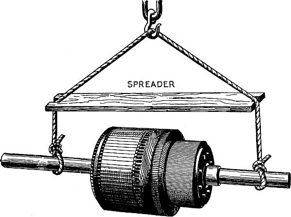
Fig. 2,798.—View of armature in transit showing use of a wooden spreader as a protection. If a chain be used in place of the rope, a padding of cloth should be placed around the armature shaft and special care taken that the chain does not scratch the commutator.
Ques. If an armature cannot be placed at once in its final position what should be done?
Ans. It may be laid temporarily upon the floor, if a sheet of cardboard or cloth be placed underneath the armature as a protection for the windings; in case the armature is not to be used for some time, it is better practice to place it in a horizontal position on two wooden supports near the shaft ends.
Ques. What kind of base should be used with a belt driven generator or motor?
Ans. The base should be provided with V ways and adjusting screws for moving the machine horizontally to take up slack in the belt, as shown in fig. 2,799.
Owing to the normal tension on the belt, there is a moment exerted equal in amount to the distance from the center of gravity of the machine to the center of the belt, multiplied by the effective pull on the belt. This force tends to turn the machine about its center of gravity. By placing the screws as shown, any turning moment, as just mentioned, is prevented.
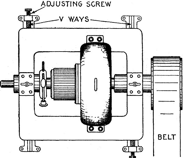
Fig. 2,799.—Plan of belt drive machine showing V ways and adjusting screws for moving the machine forward from the engine or counter shaft to take up slack in the belt.
Ques. How should a machine be assembled?
Ans. The assembling should progress by the aid of a blue print, or by the information obtained from a photograph of the complete machine as it appears when ready for service. Each part should be perfectly clean when placed in position, especially those parts between which there is friction when the machine is in operation, or across which pass lines of magnetic force; in both cases the surfaces in contact must be true and slightly oiled before placing in position.
Contact surfaces forming part of electrical circuits must also be clean and tightly screwed together. An important point to bear in mind when assembling a machine is, to so place the parts that it will not be necessary to remove any one of them in order to get some other part in its proper position. By remembering this simple rule much time will be saved, and in the majority of instances the parts will finally be better fitted together than if the task has to be repeated a number of times.
When there are two or more parts of the machine similarly shaped, it is often difficult to properly locate them, but in such cases notice should be taken of the factory marks usually stamped upon such pieces and their proper places determined from the instructions sent with the machine.
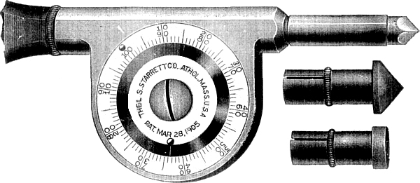
Figs. 2,800 to 2,802.—Starrett's improved speed indicator. In construction, the working parts are enclosed like a watch. The graduations show every revolution, and with two rows of figures read both right and left as the shaft may run. While looking at the watch, each hundred revolutions may be counted by allowing the oval headed pin on the revolving disc to pass under the thumb as the instrument is pressed to its work. A late improvement in this indicator consists in the rotating disc, which, being carried by friction may be moved to the starting point where the raised knobs coincide. When the spindle is placed in connection with the revolving shaft, pressing the raised knob with the thumb will prevent the disc rotating, while the hand of the watch gets to the right position to take the time. By releasing the pressure the disc is liberated for counting the revolutions of the shaft when every 100 may be noted by feeling the knob pass under the thumb lightly pressed against it, thus relieving the eye, which has only to look on the watch to note the time.
Ques. What should be noted with respect to speed of generator?
Ans. Each generator is designed to be run at a certain speed in order to develop the voltage at which the machine is rated. The speed, in revolutions per minute, the pressure in volts, and the capacity or output in watts (volts × amperes) or in kilowatts (thousands of watts) are generally stamped on a nameplate screwed to the machine.
This requirement frequently requires calculations to be made by the erectors to determine the proper size pulleys to employ to obtain the desired speed.
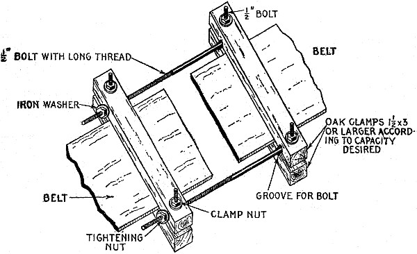
Fig. 2,803.—Home made belt clamp. It is made with four pieces of oak of ample size to firmly grip the belt ends where the bolts are tightened. The figure shows the clamp complete and in position on the belt and clearly illustrates the details of construction. In making the long bolts the thread should be cut about three-quarter length of bolt and deep enough so that the nuts will easily screw on.
Example.—What diameter of engine pulley is required to run a dynamo at a speed of 1,450 revolutions per minute the dynamo pulley being 10 inches in diameter and the speed of engine, 275 revolutions per minute?
The diameter of pulley required on engine is 10 × (1,450 ÷ 275) = 53 inches, nearly.
Rule.—To find the diameter of the driving pulley, multiply the speed of the driven pulley by its diameter, divide the product by the speed of the driver and the answer will be the size of the driver required.
Example.—If the speed of an engine be 325 revolutions per minute, diameter of engine pulley 42 inches, and the speed of the dynamo 1,400 revolutions per minute, how large a pulley is required on dynamo?
The size of the dynamo pulley is 42 × (325 ÷ 1,400) = 9¾ inches.
Rule.—To find the size of dynamo pulley, multiply the speed of engine by the diameter of engine wheel and divide the product by the speed of the dynamo.
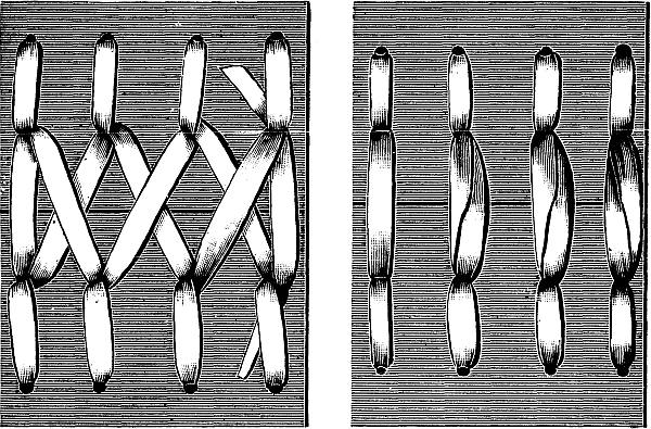
Figs. 2,804 and 2,805.—A good method of lacing a belt. The view at the left shows outer side of belt, and at the right, inner or pulley side.
Example.—If a steam engine, running 300 revolutions per minute, have a belt wheel 48 inches in diameter, and be belted to a dynamo having a pulley 12 inches in diameter, how many revolutions per minute will the dynamo make?
The speed of dynamo will be 300 × (48 ÷ 12) = 1,200 rev. per min.
Rule.—When the speed of the driving pulley and its diameter are known, and the diameter of the driven pulley is known, the speed of the driven pulley is found by multiplying the speed of the driver by its diameter in inches and dividing the product by the diameter of the driven pulley.
Example.—What will be the required speed of an engine having a belt wheel 46 inches in diameter to run a dynamo 1,500 revolutions per minute, the dynamo pulley being 11 inches in diameter?
The speed of the engine is 1,500 × (11 ÷ 46) = 359 rev. per min. nearly.
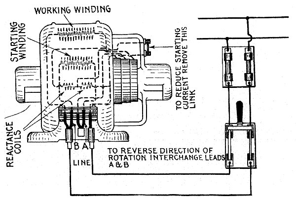
Fig. 2,806.—Wiring diagram and directions for operating Holzer-Cabot single phase self-starting motor. Location: The motor should be placed in as clear and dry a location as possible, away from acid or other fumes which would attack the metal parts or insulation, and should be located where it is easily accessible for cleaning and oiling. Erection: The motor should be set so that the shaft is level and parallel with the shaft it is to drive so that the belt will run in the middle of the pulleys. Do not use a belt which is too heavy or too tight for the work it has to do, as it will materially reduce the output of the motor. The belt should be from one-half to one inch narrower than the pulley. Rotation: In order to reverse the direction of rotation, interchange leads A and B. Suspended Motors: Motors with ring oil bearings may be used on the wall or ceiling by taking off end caps and revolving 90 or 180 degrees until the oil wells come directly below the bearings. Starting: Motors are provided with link across two terminals on the upper right hand bracket at the front of the motor and with this connection should start considerable overloads. If the starting current be too great with this connection, it may be reduced by removing the link. Temperatures: At full load the motor will feel hot to the hand, but this is far below the danger point. If too hot for touch, measure temperature with a thermometer by placing bulb against field winding for 10 minutes, covering thermometer with cloth or waste. The temperature should not exceed 75 degrees Fahr. above the surrounding air. Oiling: Fill the oil wells to the overflow before starting and keep them full. See that the oil rings turn freely with shaft. Care: The motor must be kept clean. Smooth collector rings with sandpaper and see that the brushes make good contact. When brushes become worn they may be reversed. When fitting new brushes or changing them always sandpaper them down until they make good contact with the collector rings, by passing a strip of sandpaper beneath the brush.
Rule.—To find the speed of engine when diameter of both pulleys, and speed of dynamo are given, multiply the dynamo speed by the diameter of its pulley and divide by the diameter of engine pulley.
Ques. How are the diameters and speeds of gear wheels figured?
Ans. The same as belted wheels, using either the pitch circle diameters or number of teeth in each gear wheel.
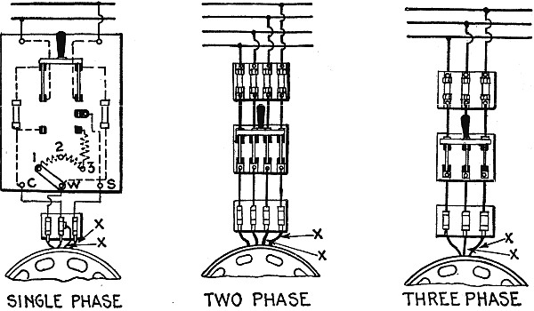
Figs. 2,807 to 2,809.—Wiring diagrams and directions for operating Holzer-Cabot slow speed alternating current motors. Erecting: In installing the motor, be sure the transformer and wiring to the motor are large enough to permit the proper voltage at the terminals. If too small, the voltage will drop and reduce the capacity of the motor. Oiling: Maintain oil in wells to the overflow. Starting: Single phase motors are started by first throwing the starting switch down into the starting position, and when the motor is up to speed, throwing it up into the running position. Do not hold the switch in starting position over 10 seconds. Starter for single phase motors above ½ H.P. are arranged with an adjusting link at the bottom of the panel. The link is shown in the position of least starting torque and current. Connect from W to 2 or W to 3 for starting heavier loads. Two or three phase motors are started simply by closing the switch. These motors start full load without starters. The motor should start promptly on closing the switch. It should be started the first time without being coupled to the line shaft. If the motor start free, but will not start loaded, it shows either that the load upon the motor is too great, the line voltage too low, or the frequency too high. The voltage and frequency with the motor running should be within 5% of the name plate rating and the voltage with 10 to 15% while starting. If the motor do not start free, either it is getting no current or something is wrong with the motor. In either case an electrician should be consulted. Solution: To reverse the direction of rotation interchange the leads marked "XX" in the diagrams. Temperature: At full load the motor should not heat over 75 degrees Fahr. above the temperature of the surrounding air; if run in a small enclosed space with no ventilation, the temperature will be somewhat higher.
Ques. What should be noted with respect to generator pulleys?
Ans. A pulley of certain size is usually supplied with each generator by its manufacturer, and it is not generally advisable to depart much from the dimensions of this pulley. Accordingly, the solution of the pulley problem usually consists in finding the necessary diameter of the driving pulley relative to that of the pulley on the generator in order to furnish the required speed.
Ques. What is the chief objection to belt drive?
Ans. The large amount of floor space required.
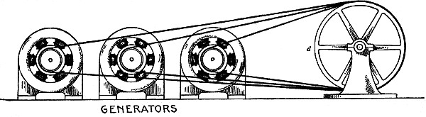
Fig. 2,810.—Tandem drive for economizing floor space with belt transmission. Belts of different lengths are used, as shown, each of which passes over the driving wheel d of the engine, and then over the pulley wheel of one of the generators. In such an arrangement the belts would be run lengthwise through the room in which the machines are placed, and it is obvious that since the width of the room would be governed by the width of the machines thus installed, this method is a very efficient one for accomplishing the end in view.
Ques. How may the amount of space that would ordinarily be required for belt drive, be reduced?
Ans. By driving machines in tandem as in fig. 2,810, or by the double pulley drive as in fig. 2,811.
Ques. What is the objection to the tandem method?
Ans. The most economical distance between centers cannot be employed for all machines.
Ques. What is the objectionable tendency in resorting to floor economy methods with belt transmission?
Ans. The tendency to place the machines too closely together. This is poor economy as it makes the cleaning of the machines a difficult and dangerous task; it is therefore advisable to allow sufficient room for this purpose regardless of the method of belting employed.
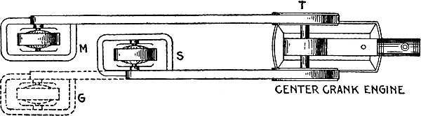
Fig. 2,811.—Double pulley drive for economizing floor space with belt transmission. Where a center crank engine is used both pulleys may be employed by belting a machine to each as shown. Although considerable floor space would be saved by the use of this scheme if the generators thus belted were placed at M and G yet still more floor space would be saved by having them occupy the positions indicated at M and S.
Ques. What is the approved location for an alternator exciter?
Ans. To economize floor space the exciter may be placed between the alternator and engine at S in fig. 2,811.
Belts.—In the selection of a belt, the quality of the leather should be first under consideration. The leather must be firm, yet pliable, free from wrinkles on the grain or hair side, and of an even thickness throughout.

Fig. 2,812.—Separately excited belt driven alternator showing approved location of exciter. In an electrical station where alternating current is generated, the alternators for producing the current generally require separate excitation for their field windings; that is, it is usually necessary to install in conjunction with an alternator a small dynamo for supplying current to the alternator field. The exciter is a comparatively small machine; in fact, it requires only about 1 per cent. of the capacity of the alternator which it excites, and so being small is often belted to an auxiliary pulley mounted on the alternator shaft. Considerable floor space would be occupied by an installation of this nature if the exciter be placed at M, and belted to the alternator as indicated by the dotted lines. By locating the exciter at S, between the alternator and the engine, much floor space will be saved and the general appearance of the installation improved.
If the belt be well selected and properly handled, it should do service for twenty years, and even then if the worn part be cut off, the remaining portion may be remade and used again as a narrower and shorter belt.
Besides leather belts, there are those made of rubber which withstand moisture much better than leather belts, and which also possess an excellent grip on the pulley; they are, however, more costly and much less durable under normal conditions.
In addition to leather and rubber belts, there are belts composed of cotton, of a combination of cotton and leather, and of rope. The leather belt, however, is the standard and is to be recommended.
Equally important with the quality of a belt is its size in order to transmit the necessary power.
The average strain under which leather will break has been found by many experiments to be 3,200 pounds per square inch of cross section. A good quality of leather will sustain a somewhat greater strain. In use on the pulleys, belts should not be subjected to a greater strain than one eleventh their tensile strength, or about 290 pounds to the square inch or cross section. This will be about 55 pounds average strain for every inch in width of single belt three-sixteenths inch thick. The strain allowed for all widths of belting—single, light double, and heavy double—is in direct proportion to the thickness of the belt.
Ques. How much horse power will a belt transmit?
Ans. The capacity of a belt depends on, its width, speed, and thickness. A single belt one inch wide and travelling 1,000 feet per minute will transmit one horse power; a double belt under the same conditions, will transmit two horse power.
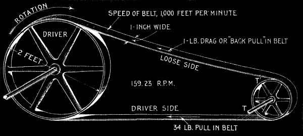
Fig. 2,813.—One horse power transmitted by belt to illustrate the rule given above. A pulley is driven by a belt by means of the friction between the surfaces in contact. Let T be the tension on the driving side of the belt, and T', the tension on the loose side; then the driving force = T-T'. In the figure T is taken at 34 lbs. and T' at 1 lb.; hence driving force = 34-1 = 33 lbs. Since the belt is travelling at a velocity of 1,000 feet per minute the power transmitted = 33 lbs. × 1,000 ft. = 33,000 ft. lbs. per minute = 1 horse power.
This corresponds to a working pull of 33 and 66 lbs. per inch of width respectively.
Example.—What width double belt will be required to transmit 50 horse power travelling at a speed of 3,000 feet per minute?
The horse power transmitted by each inch width of double belt travelling at the stated speed is
( 1 × 3,000 / 1,000 ) × 2 = 6,
hence the width of belt required to transmit 50 horse power is
50 ÷ 6 = 8.33, say 8 inches.
Ques. At what velocity should a belt be run?
Ans. At from 3,000 to 5,000 feet per minute.
Ques. How may the greatest amount of power transmitting capacity be obtained from belts?
Ans. By covering the pulleys with leather.
Ques. How should belts be run?
Ans. With the tight side underneath as in fig. 2,814.
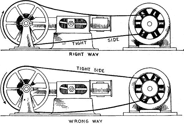
Figs. 2,814 and 2,815.—Right and wrong way to run a belt. The tight side should be underneath so as to increase the arc of contact and consequently the adhesion, that is to say, a better grip, is in this way obtained.
Ques. What is a good indication of the capacity of a belt in operation?
Ans. Its appearance after a few days' run.
If the side of the belt coming in contact with the pulley assume a mottled appearance, it is an indication that the capacity of the belt is considerably in excess of the power which it is transmitting, inasmuch as the spotted portions of the belt do not touch the pulley; and in consequence of this there is liable to be more or less slipping.
Small quantities of a mixture of tallow and fish oil which have previously been melted together in the proportion of two of the former to one of the latter, will, if applied to the belt at frequent intervals, do much toward softening it, and thus by permitting its entire surface to come in contact with the pulley, prevent any tendency toward slipping. The best results are obtained when the smooth side of the belt is used next to the pulley, since tests conducted in the past prove that more power is thus transmitted, and that the belt lasts longer when used in this way.
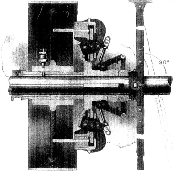
Fig. 2,816.—The Hill friction clutch pulley for power control. The clutch mechanism will start a load equivalent to the double belt capacity of the pulley to which the clutch is attached.
Ques. What is the comparison between the so called endless belts and laced belts?
Ans. With an endless belt there is no uneven or noisy action as with laced belts, when the laced joint passes over the pulleys, and the former is free from the liability of breakage at the joint.
Ques. How should a belt be placed on the pulleys?
Ans. The belt should first be placed on the pulley at rest, and then run on the other pulley while the latter is in motion.
The best results are obtained, and the strain on the belt is less, when the speed at which the moving pulley revolves is comparatively low. With heavy belts, particular care should be taken to prevent any portion of the clothing being caught either by the moving belt or pulleys, as many serious accidents have resulted in the past from carelessness in regard to this important detail. The person handling the belt should, therefore, be sure of a firm footing, and when it is impossible to secure this, it is advisable to stop the engine and fit the belt around the engine pulley as well as possible by the aid of a rope looped around the belt.
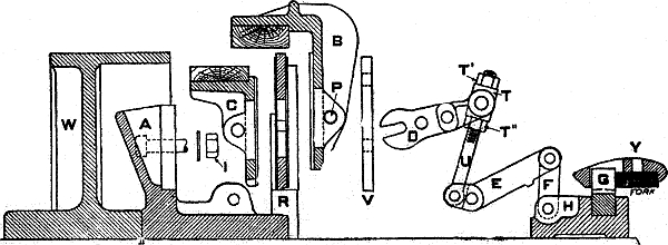
Fig. 2,817—Sectional view of Hill clutch mechanism. In every case the mechanism hub A, and in a clutch coupling the ring W, is permanently and rigidly secured to the shaft and need not be disturbed when removing the wearing parts. When erected, the adjustment should be verified, and always with the clutch and ring engaged and at rest. If the jaws do not press equally on the ring, or if the pressure required on the cone be abnormal, loosen the upper adjusting nuts T´ on eye bolts and set up the lower adjusting nuts T´´ until each set of jaws is under the same pressure. Should the clutch then slip when started it is evident that the jaw pressure is insufficient and a further adjustment will be necessary. All clutches are equipped throughout with split lock washers. Vibration or shock will not loosen the nuts if properly set up. The jaws can be removed parallel to the shaft as follows: Remove the gibs V, and withdraw the jaw pins P, then pull out the levers D. Do not disturb the eye bolt nuts T´ and T´´. The outside jaws B can now be taken out. Remove the bolt nuts I allowing the fulcrum plates R to be taken off. On the separable hub pattern the clamping bolts must be taken out before fulcrum plate is removed. The inside jaws C may now be withdrawn. Always set the clutch operating lever in the position as shown in fig. 2,816 to avoid interference with mechanism parts. Oil the moving parts of the clutch. Keep it clean. Examine at regular intervals.
Ques. Under what conditions does a belt drive give the best results?
Ans. When the two pulleys are at the same level.
If the belt must occupy an inclined position it should not form a greater angle than 45 degrees with the horizontal.
Ques. What is a characteristic feature in the operation of belts, and why?
Ans. Belts in motion will always run to the highest side of a pulley; this is due partially to the greater speed in feet per minute developed at that point owing to the greater circumference of the pulley, and also to the effects of centrifugal force.
If, therefore, the highest sides of both pulleys be in line with each other, and the shafts of the respective pulleys be parallel to each other, there will be no tendency for the belt to leave the pulleys when once in its proper position. In order that these conditions be maintained, the belt should be no more than tight enough to prevent slipping, and the distance between the centers of the pulleys should be approximately 3.5 times the diameter of the larger one.
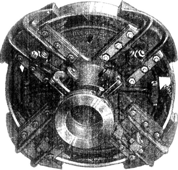
Fig. 2,818.—Hill clutch mechanism Smith type. The friction surfaces are wood to iron, the wood shoes being made from maple. All parts of the toggle gear are of steel and forgings with the exception of the connection lever which is of cast iron.
Ques. What minor appurtenances should be provided in a station?
Ans. Apparatus should be installed as a prevention against accidents, such as fire, and protection of attendants from danger.
In every electrical station there should be a pump, pipes and hose; the pump may be either directly connected to a small electric motor or belted to a countershaft, while the pipes and hose should be so placed that no water can accidentally reach the generators and electrical circuits. A number of fire bucket filled with water should be placed on brackets around the station, and with these there should be an equal number of bucket containing dry sand, the water being used for extinguishing fire occurring at a distance from the machines and conductors, and the sand for extinguishing fire in current carrying circuits where water would cause more harm than benefit. To prevent the sand being blown about the station, each sand bucket, when not in use, should be provided with a cover.
Neat cans and boxes should be mounted in convenient places for greasy rags, waste, nuts, screws, etc., which are used continually and which therefore cannot be kept in the storeroom.
While it is important to guard against fire in the station, it is equally necessary to provide for personal safety. All passages and dark pits should therefore be thoroughly lighted both day and night, and obstacles of any nature that are not absolutely necessary in the operation of the station, should be removed. Moving belts, and especially those passing through the floor, should be enclosed in iron railings. If high voltages be generated, it is well to place a railing about the switchboard to prevent accidental contact with current carrying circuits, and in such cases it is also advisable to construct an insulated platform on the floor in front of the switchboard.
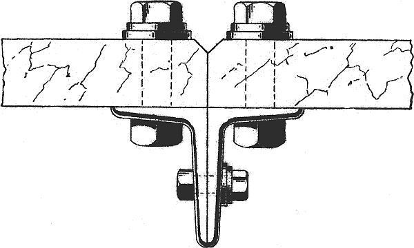
Fig. 2,819.—Method of joining adjacent switchboard panels.
Switchboards.—The plan of switchboard wiring for alternating current work depends upon the system in use and this latter may be either of the single phase, two phase, three phase, or monocyclic types. The general principles in all these cases, however, are practically identical.
Fig. 2,820 shows the switchboard wiring for a single phase alternator. As an aid in reading the diagram, the conductors carrying alternating current are represented by solid lines, and those carrying direct current, by dotted lines.
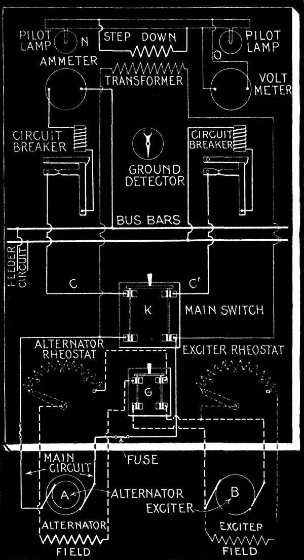
Fig. 2,820.—Switchboard wiring for a single phase separately excited alternator. The direct current circuits are represented by dotted lines, and the alternating current circuit, by solid lines.
The exciter shown at the right is a shunt wound machine. By means of the exciter rheostat, the voltage for exciting the field winding of the alternator is varied; this, in turn, varies the voltage developed in the alternator since the main leads of the exciter are connected through a double pole switch G to the field winding of the alternator.
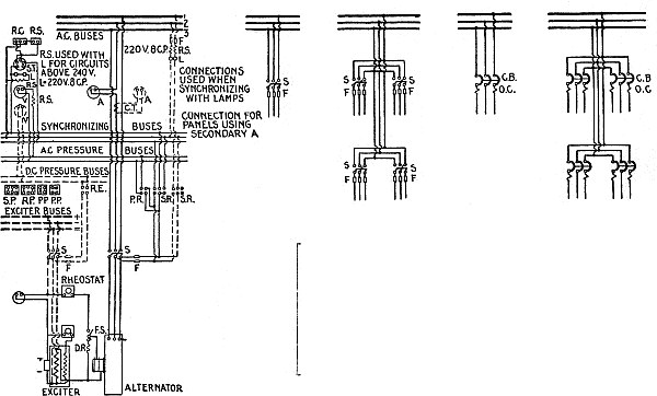
Figs. 2,821 to 2,825.—General Electric diagrams of connections. A, ammeter; C.B, circuit breaker; C.P, candle power; C.T, current transformer; D.R, discharge resistance; F, fuse; F.S, field switch; L, lamp; O.C, overload coil; P.P, pressure plug; P.R, pressure receptacle; R.C, reactance; rheo, rheostat; R.P, synchronizing plug, running; R.S, resistance; S, switch; S.I, synchronism indicator; S.P, synchronizing plug, starting; S.R, synchronizing receptacle; V, voltmeter.
A rheostat is also introduced in the alternator field winding circuit to adjust the alternator pressure. It may seem unnecessary to employ a rheostat in each of two separate field circuits to regulate the voltage of the alternator, but these rheostats are not both used to produce the same result. When a considerable variation of pressure is required, the exciter rheostat is manipulated, whereas for a fine adjustment of voltage the alternator rheostat is preferably employed.
Sometimes a direct current ammeter is introduced in the alternator's field circuit to aid in the adjustment.
The main circuit of alternator after being protected on both sides by fuses, runs to the double pole switch K. These fuses serve as a protection to the alternator in case of a short circuit at the main switch. It will be noticed the fuses are of the single pole type and are mounted a considerable distance apart; this is to prevent any liability of a short circuit between them in case of action. Enclosed fuses are now used entirely for such work, since in these there is no danger of heated metal being thrown about and causing damage when the fuse wire is melted. Enclosed fuses are also more readily and quickly replaced than open fuses, the containing tube of each being easy to adjust in circuit, and when the fuse wire within is once melted the tube is discarded for a new one.
The main circuit after passing through the main switch is further protected on both sides by circuit breakers. Leaving these protective devices, the left hand side of the circuit includes the alternating current ammeter, and then connects with one of the bus bars. The right hand side of the circuit runs from the circuit breaker to the other bus bar. As many feeder circuits may be connected to the bus bars and supplied with current by the alternator as the capacity of this machine will permit. If, however, there be more than one feeder circuit, each must be wired through a double pole switch.
In alternating current work the pressures dealt with are much greater than those in direct current installations, so that proportionate care must be taken in the wiring to remove all possibility of grounds.
To locate such troubles, however, should they occur, a ground detector is provided. For this class of work the ground detector must be an instrument especially designed for high pressure circuits. Two of its terminals should be connected to the line wires and the third, to ground; in case of a leak on the line, a current will then flow through the detector and by the position of the pointer the location and seriousness of the leak may be judged.
A step down transformer is also rendered necessary for the voltmeter and the pilot lamps, owing to the high voltage in use. The primary winding of the transformer is connected across the main circuit of the alternator. This connection should never be made so that it will be cut out of circuit when the main switch is open, for it is always advisable to consult the voltmeter before throwing on the load by closing this switch.
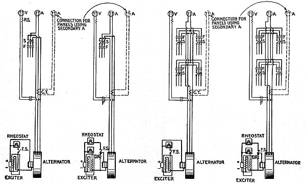
Figs. 2,826 to 2,829.—General Electric diagrams of connections. A, ammeter; C.B, circuit breaker; C.P, candle power; C.T, current transformer; D.R, discharge resistance; F, fuse; F.S, field switch; L, lamp; O.C, overload coil; P.P, pressure plug; P.R, pressure receptacle; R.C, reactance; rheo, rheostat; R.P, synchronizing plug, running; R.S, resistance; S, switch; S.I, synchronous indicator: S.P, synchronizing plug, starting; S.R, synchronizing receptacle: V, voltmeter.
Ques. How does the switchboard wiring for a two phase system differ from the single phase arrangement shown in fig. 2,820?
Ans. It is practically the same, except for the introduction of an extra ammeter and a compensator in each of the outside wires, and in the use of a four pole switch in place of the two pole main switch.
The ammeters, of course, are for measuring the alternating currents in each of the two phases or legs of the system, and the compensators are two transformers with their primary coils in series with the outside wires and their secondary coils in series with each other across the outside wires. The transformers thus connected are known as compensators or pressure regulators, and as such compensate for the drop in pressure on either side of the system.
Ques. How is the four pole main switch wired?
Ans. Its two central terminals which connect directly with the line wires, are joined together by a conductor, and from this point one wire is led off. This wire, together with the two outside wires, form the feeders of the system.
Ques. How many voltmeters are required for the two phase system?
Ans. One voltmeter is sufficient on the board if a proper switching device be employed to shift its connections across either of the two circuits; otherwise, two voltmeters will be necessary, one bridged across each of these respective circuits.
The same reasoning holds true in regard to ground detectors, so that one or two of these will be required, depending upon the aforementioned conditions.
Ques. What are the essential points of difference between the single phase switchboard wiring as shown in fig. 2,820, and that required for a three wire three phase system?
Ans. The three phase system requires the use of a three pole switch in place of the two pole switch; the insertion of an ammeter, a circuit breaker, and a compensator in each of the three wires of the system; the presence of two ground detectors instead of one, and the addition of a voltmeter switch if but one voltmeter be provided, or else the installation of two voltmeters, connected the one between the middle wire and outer right hand wire, and the other between the middle wire and outer left hand wire.
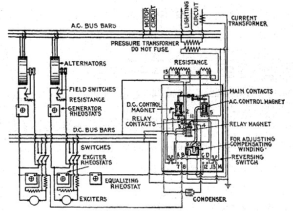
Fig. 2,830.—Diagram of switchboard connections for General Electric automatic voltage regulator with two exciters and two alternators.
Ques. Mention a few points relating to lightning arresters.
Ans. In most cases where direct current is used they are mounted on the walls of the station near the place at which the line wires enter. If they be mounted outside the station at this point, special precautions should be taken to keep them free from moisture by enclosing them in iron cases, but no matter where they are located it is necessary that they be dry in order to work properly.
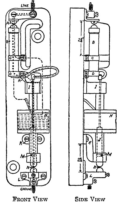
Figs. 2,831 and 2,832.—Garton-Daniels alternating current lightning arrester; diagram showing connections. A lightning discharge takes the path indicated by the dotted line, across the upper air gap A, through resistance rod B, C, D, across copper strip R on the base, thence flowing to ground through the movable plunger M, lower on gap N, and ground binding post L. The discharge path is practically straight, contains an air gap, distance of but 3/32 inch, a series resistance averaging but 225 ohms. The lightning discharge does not flow through the flexible lead connecting band D on the lower end of the resistance rod with the top of the movable plunger. These two points are electrically connected by the heavy copper strip R, and lightning discharges generally, if not always, take the path across this copper strip in preference to flowing through the inductance of the one turn of flexible cable. When a discharge occurs from line to ground through any lightning arrester, the air gaps arc over, and so there is offered a path from line to ground for the line current. This flow of line current following the lightning discharge to ground may vary anywhere from a small capacity current where the arrester is installed on an ungrounded circuit, a moderately heavy flow on a partially grounded circuit, to a very heavy flow on a grounded circuit—either a circuit operated as a dead grounded circuit, or a circuit which has become accidentally grounded during a storm. The path taken by this flow of line current from line to ground may be traced by following the path shown by the dashed line. It, as seen, crosses upper air gap A, flows through section B of the resistance rod to band C. Leaving band C it flows through the magnet winding H, thence to band D on the resistance rod, through flexible lead to upper end of movable plunger, through movable plunger, across lower air gap N, to ground binding post L, thence to ground. The function of the short length of resistance rod CD is as follows: It has an ohmic resistance of about 30 ohms but is non-inductive. Magnet winding H, connected to bands C and D on the ends of this short length of rod has an ohmic resistance of 3 ohms, but is highly inductive. Lightning discharges being of high frequency take the higher resistance but non-inductive path CD in their passage from line to ground. The flow of normal current from line to ground being of a very low frequency, 25 or 60 cycles in ordinary alternating current circuits, zero in direct current circuits—takes the low resistance path through coil H in its path to ground. Section CD of the rod is used therefore simply to shunt the inductance of winding H to high frequency lightning discharges, leaving the lightning discharge path in the arrester a non-inductive highly efficient path. In all Garton-Daniels A. C. lightning arresters operating on non-grounded or partially grounded circuits, the action of the air gaps and series resistance are together sufficient to extinguish the flow of normal current to ground at the zero point of the generator voltage wave. If, however, as frequently happens, the line grounds accidentally during a storm, then the arrester does not have to depend for its proper operation on the arc extinguishing properties of the air gaps and resistance, but the heavier flow of line current through the arrester energizes the movable plunger, which raises upward in the coil, opening the circuit between the discharge point M and the lower end of the plunger. To limit the flow of line current to ground the resistance rod B is provided, there being approximately 225 ohms between the discharge point A and clamp C in the 2,500 volt arrester. This feature is particularly effective where the circuit is temporarily or accidentally grounded. The series resistance prevents a heavy short circuit through the arrester and limits the current to a value that is readily broken by the cut out and is not enough to impede the passage of the discharge.
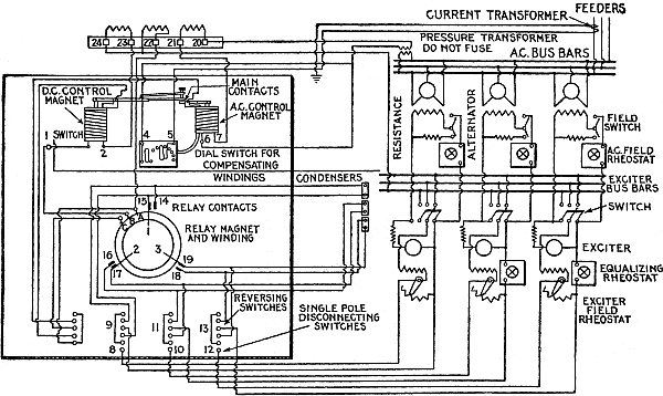
Fig. 2,833.—Diagram of switchboard connections for General Electric automatic voltage regulator with three exciters and three alternators.
If possible, one place should be set aside for them and a marble or slate panel provided on which they may be mounted.
Wooden supports are undesirable for lightning arresters on account of the fire risk incurred; this, however, may be reduced to a minimum by employing skeleton boards and using sheets of asbestos between the arresters and the wood.
In parts of the country where lightning is of common occurrence and where overhead circuits are installed which carry high pressures, heavy currents, and extend over considerable territory, it is advisable to have the station well equipped with lightning arresters of the most improved types.
In each side of the main circuit, between the lightning arrester connections and the switchboard apparatus there should be connected a choke coil or else each of the main conductors at this point should be tightly coiled up part of its length to answer the same purpose.
A quick and effective way of coiling up a wire consists in wrapping around a cylindrical piece of iron or wood that part of the conductor in which it is desired to have the coils, the desired number of times, and then withdrawing the cylindrical piece. The coils, each of which may contain 50 or 200 turns, thus inserted in the main circuit introduce a high resistance or reluctance to a lightning current, and thus prevent it passing to the generator; there will, however, be an easy path to earth afforded it through the lightning arrester, and so no damage will be done. Coils of the nature just mentioned may advantageously be introduced between the generator and switchboard to take up the reactive current developed upon the opening of the circuit, and in the case of suspended conductors, the coils may be used to take up the slack by the spring-like effect produced by them.
The safety of the operator should be especially considered in the design of high pressure alternating current switchboards.
Such protection may be secured by screening all the exposed terminals, or preferably by mounting all the switch mechanism on the back of the board with simply the switch handle projecting through to the front; by pushing or pulling the switch handle, the connections can thus be shifted either to one side of the system or to the other.
Ques. Upon what does the work of assembling a switchboard depend?
Ans. It depends almost entirely upon the size of the plant, varying from the simple task of mounting a single panel in the case of an isolated plant, to the more difficult problem of supporting a large number of panels in a central station.
Ques. When the material chosen for a switchboard must be shipped a considerable distance, what form of board should be used?
Ans. The board units or "slabs" should be of small dimensions, to avoid the liability of breakage and expense of renewal when a unit becomes cracked or machine injured.
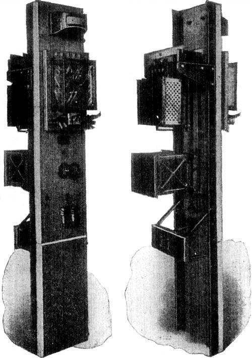
Figs. 2,834 and 2,835.—Front and rear views showing General Electric automatic voltage regulator mounted on switchboard panel.
Ordinarily, switchboards vary from five to eight feet in height and the widths of the panels vary from five to six feet. In some boards the seams between the slabs run vertically, and in others horizontally. In order to render the assembling of the switchboard as simple as possible, and its appearance when finished the most artistic, these seams should run horizontally rather than vertically. The edges of each of the slabs should also be chamfered so that there will be less danger of their breaking out when being mounted on the framework.
Ques. In assembling a switchboard, how should the lower slabs be placed, and why?
Ans. They should be suspended a little distance from the floor to prevent contact with any oil, dirt, water or rubbish that might be on the floor.
Ques. How are the slabs or panels supported?
Ans. They are carried on an iron or wooden framework with braces to give stability.
The braces should be securely fastened at one end to the wall of the station, and at the other end to the framework of the board, as shown in fig. 2,836.
To fasten the switchboard end of the brace directly to the slate, marble or other material composing the board is poor practice and should never be attempted.
If the station be constructed of iron, these switchboard braces must be such that they will thoroughly insulate the board and its contents from the adjoining wall.
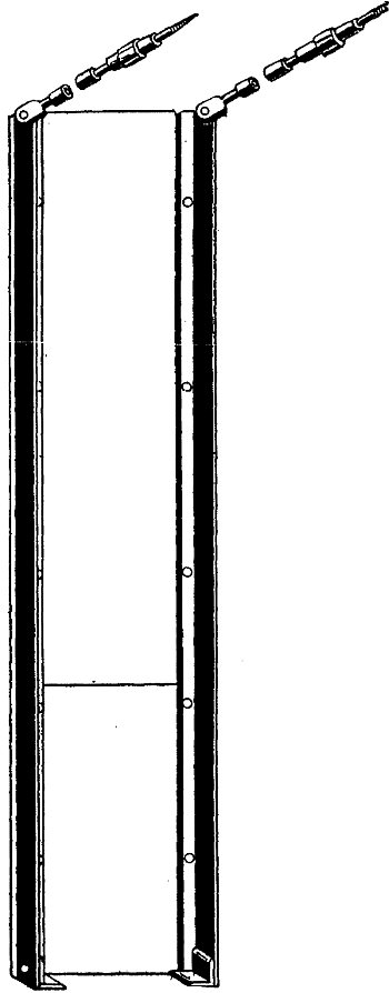
Fig. 2,836.—Method of supporting the framework of a switchboard.
Ques. What is the usual equipment of a switchboard?
Ans. It comprises switching devices, current or pressure limiting devices, indicating devices, and fuses for protecting the apparatus and circuits.
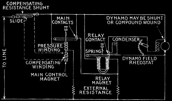
Fig. 2,837.—Diagram showing elementary connections of General Electric automatic regulator for direct current. It consists essentially of a main control magnet with two independent windings and a differentially wound relay magnet. One winding, known as the pressure winding, of the main control magnet is connected across the dynamo terminals, the other across a shunt in one of the load mains. The latter is the "compensating winding" and it opposes the action of the pressure winding so that as the load increases, a higher pressure at the dynamo is necessary to "over compound" for line drop. In ordinary practice, the voltage terminals are connected to the bus bars, and the compensating shunt inserted in one of the principal feeders of the system. In operation the shunt circuit across the dynamo field rheostat is first opened by means of a switch provided for that purpose on the base of the regulator and the rheostat turned to a point that will reduce the generator voltage 35 per cent below normal. The main control magnet is at once weakened and allows the spring to pull out the movable core until the main contacts are closed. This closes the second circuit of the differential relay, thus neutralizing its windings. The relay spring then lifts the armature and closes the relay contacts. The switch in the shunt circuit across the dynamo field rheostat is now closed, practically short circuiting the rheostat, and the dynamo voltage at once rises. As soon as it reaches the point for which the regulator has been adjusted, the main control magnet is strengthened, which causes the main contacts to open, which in turn open the relay contacts across the rheostat. The rheostat is now in the field circuit, the voltage at once falls off, the main contacts are closed, and relay armature released, and shunt circuit across the rheostat again completed. The voltage then starts to rise and this cycle of operation is continued at a high rate of vibration, maintaining not a constant but a steady voltage at the bus bars. When neither the compensating winding nor pressure wires are used, there will be no "over compounding" effect due to increase of load and a constant voltage will be maintained at the bus bars. The compensating winding on the control magnet, which opposes the pressure winding is connected across an adjustable shunt in the principal feeder circuit. As the load increases the voltage drop across the shunt increases and the effect of the compensating winding becomes greater. This will require a higher voltage on the pressure winding to open the main contacts and the regulator will therefore cause the dynamo to compensate for line drop, maintaining at the bus bars a steady voltage without fluctuations, which rises and falls with a load on the feeders, giving a constant voltage at the lamps or center of distribution. The compensating shunt may be adjusted so as to compensate for any desired line drop up to 15 per cent; it is preferably placed in the principal lighting feeder, but may be connected to the bus bars so that the total current will pass through it. The latter method, however, is sometimes desirable, as large fluctuating power loads on separate feeders might disturb the regulation of the lighting feeders. Adjustment is made by sliding the movable contact at the center of the shunt. This contact may be clamped at any desired point and determines the pressure across the compensating winding of the regulator's main control magnet. Where pressure wires are run back to the central station from the center of distribution they may be connected directly to the pressure winding of the main control magnet, and it is unnecessary to use the compensating shunt. The pressure wires take the place of the leads from the control magnet to the bus bars and maintain a constant voltage at the center of distribution.
On some switchboards are also mounted small transformers for raising or lowering the voltages, and lightning arresters as a protection from lightning. In addition to the apparatus previously mentioned nearly all switchboards carry at or near their top two or more incandescent lamps provided with shades or reflectors, for lighting the board.
Ques. What should be done before wiring a switchboard?
Ans. The electrical connections between the various apparatus mounted on the face or front of the board, are made on the back of the board. It is necessary that these connections be properly made else considerable electrical power will be wasted at this point. The wiring on the back of the board should therefore be planned out on paper before commencing the work.
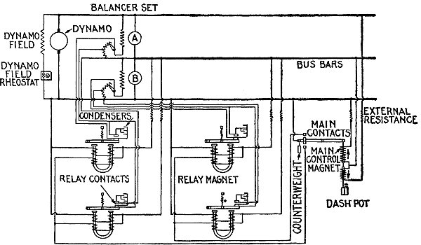
Fig. 2,838.—Diagram showing connections of General Electric automatic voltage regulator for direct current as connected for maintaining balanced voltage on both sides of a three wire system using a balancer set. In operation, should the voltage on the upper bus bars become greater than that on the lower ones, the middle and upper contacts on the regulator will close, thus opening the relay contacts to the left and closing those to the right. This inserts all the resistance in the field of balancer A, and short circuits the resistance in the field of balancer B. A will then be running as a motor, and B as a dynamo, thereby equalizing the two voltages until that on the lower bus bars becomes greater than that of the upper ones; then the regulator contacts operate in the opposite direction and balancer A is run as a dynamo, and balancer B as a motor. This cycle of operation is repeated at the rate of from three to four hundred times per minute, thus maintaining a balanced voltage on the system.
In laying out the plan of wiring care must be taken to allow sufficient contact surface at each connection; there should be not less than one square inch of contact surface allowed for each 160 amperes of current transmitted.
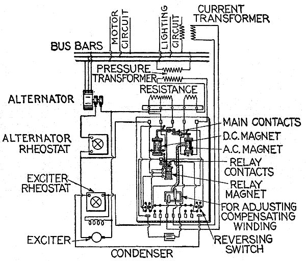
Fig. 2,839.—Diagram of connections of General Electric voltage regulators for one or more alternators using one exciter.
For the bus bars, which, by the way are always of copper, one square inch per 1,000 amperes is the usual allowance; this is equal to 1,000 circular mils of cross sectional area per ampere.
Every effort should be made to give the bus bars the greatest amount of radiation consistent with other conditions, in order that their resistances may not become excessive owing to the heat developed by the large currents they are forced to carry. Suppose, for instance, the number of amperes to be generated is such as to require bus bars having each a cross sectional area of one square inch. If the end dimensions of these bars were each 1 inch by 1 inch, there would be less radiating surface than if their dimensions were each 2 inches by ½ inch.
Operation of Alternators.—The operation of an alternator when run singly differs but little from that for a dynamo.
As to the preliminaries, the exciter must first be started. This is done in the same way as for any shunt dynamo. At first only a small current should be sent through the field winding of the alternator; then, if the exciter operates satisfactorily and the field magnetism of the operator show up well, the load may gradually be thrown on until the normal current is carried, the same method of procedure being followed as in the similar case of a dynamo.
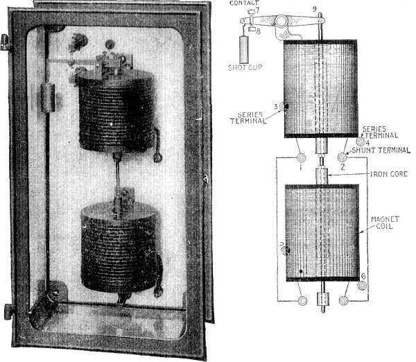
Figs. 2,840 and 2,841.—General Electric equalizer regulator designed to equalize the load on two machines, and diagram of connections.
On loading an alternator, a noticeable drop in voltage occurs across its terminals. This drop in voltage is caused in part by the demagnetization of the field magnets due to the armature current, and so depends in a measure upon the position and form of the pole pieces as well as upon those of the teeth in the armature core. The resistance of the armature winding also causes a drop in voltage under an increase of load.
Another cause which may be mentioned is the inductance of the armature winding, which is in turn due to the positions of the armature coils with respect to each other and also with respect to the field magnets.
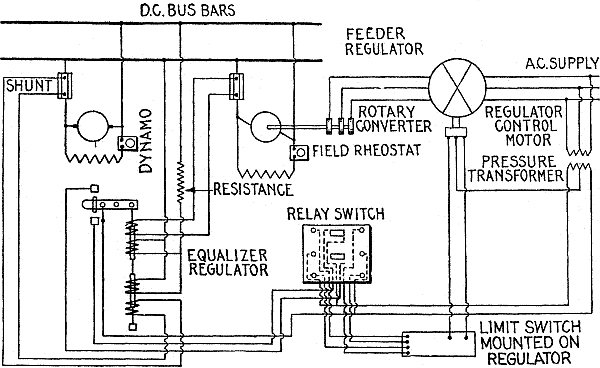
Fig. 2,842.—Connection of General Electric equalizing regulator for equalizing loads on an engine driven dynamo and rotary converter running in parallel. Should the load on the dynamo become greater than that on the rotary converter, the middle and upper contacts on the regulator close, and thus by means of the relay switch and control motor, cause the feeder regulator to boost the voltage on the rotary until the loads again become equal. Should the load on the rotary converter become greater than that on the generator, the regulator contacts operate in the reverse direction and the feeder regulator is caused to buck the rotary voltage.
Alternators in Parallel.—When the load on a station increases beyond that which can conveniently be carried by one alternator, it becomes necessary to connect other alternators in parallel with it. To properly switch in a new machine in parallel with one already in operation and carrying load, requires a complete knowledge of the situation on the part of the attendant, and also some experience.
The connections for operating alternators in parallel are shown in fig. 2,843. In the illustration the alternator A is in operation and is supplying current to the bus bars. The alternator B is at rest. The main pole switch B' by means of which this machine can be connected into circuit is therefore open.
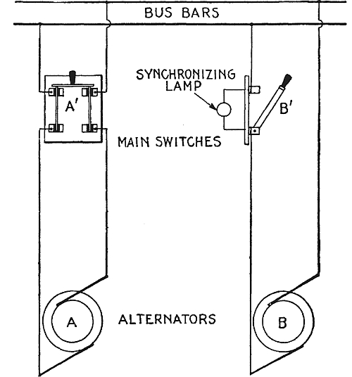
Fig. 2,843.—Method of synchronizing with one lamp; dark lamp method. Assuming A to be in operation, B, may be brought up to approximately the proper speed, and voltage. Then if B, be run a little slower or faster than A, the synchronizing lamp will glow for one moment and be dark the next. At the instant when the pressures are equal and the machines in phase, the lamp will become dark, but when the phases are in quadrature, the lamp will glow at its maximum brilliancy. Since the flickering of the lamp is dependent upon the difference in frequency, the machines should not be thrown in parallel while this flickering exists. The nearer alternator approaches synchronism, in adjusting its speed, the slower the flickering, and when the flickering becomes very slow, the incoming machine may be thrown in the moment the lamp is dark by closing the switch. The machines are then in phase and tend to remain so, since if one slow down, the other will drive it as a motor.
Now, if the load increase to such extent as to require the service of the second alternator B, it must be switched in parallel with A. In order that both machines may operate properly in parallel, three conditions must be satisfied before they are connected together, or else the one alternator will be short circuited through the other, and serious results will undoubtedly follow.
Accordingly before closing main switch B, it is necessary that
1. The frequencies of both machines be the same; 2. The machines must be in synchronism; 3. The voltages must be the same.
Ques. How are the frequencies made the same?
Ans. By speeding up the alternator to be cut in, or change the speed of both until frequency of both machines is the same.
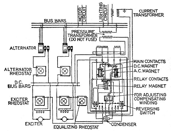
Fig. 2,844.—Diagram of connections of General Electric automatic voltage regulator for several alternators running in parallel with exciters in parallel.
Ques. How are the alternators synchronized or brought in phase?
Ans. The synchronism of the alternators is determined by employing some form of synchronizer, as by the single lamp method of fig. 2,843, or the two lamp method of fig. 2,845.
Ques. In synchronizing by the one lamp method, when should the incoming machine be thrown in?
Ans. It is advisable to close the switch when the machines are approaching synchronism rather than when they are receding from it, that is to say, the instant the lamp becomes dark.
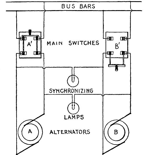
Fig. 2,845.—Method of synchronizing with two lamps; dark lamp method. The two synchronizing lamps are connected as shown, and each must be designed to supply its rated candle power at the normal voltage developed by the alternators. Now since the alternators are both running under normal field excitation the left hand terminals of each of them will alternately be positive and negative in polarity, while the right hand terminals are respectively negative and positive in polarity. If, however, the alternators be in phase with each other, the left hand terminals of both of them will be positive while the right hand terminals are negative, and when the left hand terminals of both machines are negative the right hand terminals will be positive. Hence, when the machines are in phase there will be no difference of pressure between the left hand terminals or between the right hand terminals of the two machines. Hence, if the synchronizing lamps be connected as shown, both will be dark. The instant there is a difference of phase, both lamps will glow attaining full candle power when the difference of phase has reached a maximum. As the alternators continue to come closer in step, the red glow will gradually fade away until the lamps become dark. Then the switch may be closed, thereby throwing the two machines in parallel. If the intervals between the successive lighting up of the lamps are of short duration it is advisable to wait until these become longer even though the other conditions are satisfied, because where the phases pass each other rapidly there is a greater possibility of not bringing them together at the proper instant. An interval of not less than five seconds should therefore be allowed between the successive lighting up of the lamps, before closing the switch.
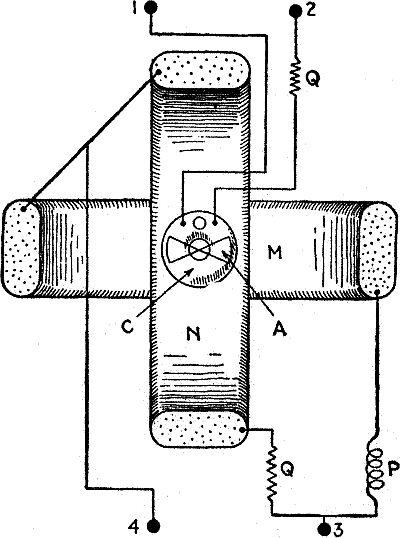
Fig. 2,846.—Inductor type synchroscope. This type is especially applicable where pressure transformers are already installed for use with other meters. As it requires only about ten apparent watts it may be used on the same transformers with other meters. There are three stationary coils, N, M and C, and a moving system, comprising an iron armature, A, rigidly attached to a shaft suitably pivoted and mounted in bearings. A pointer is also attached to the shaft. The moving system is balanced and is not subjected to any restraining force, such as a spring or gravity control. The axes of the coils N and M are in the same vertical plane, but 90 degrees apart, while the axis of C is in a horizontal plane. The coils N and M are connected in "split phase" relation through an inductive resistance P and non-inductive resistance Q, and these two circuits are parallel across the bus bar terminals 3 and 4 of the synchroscope. Coil C is connected through a non-inductive resistance across the upper machine terminals 1 and 2 of the synchroscope. In operation, current in the coil C magnetizes the iron core carried by the shaft and the two projections, marked A and "iron armature." There is however, no tendency to rotate the shaft. If current be passed through one of the other coils, say M, a magnetic field will be produced parallel with its axis. This will act on the projections of the iron armature, causing it to turn so that the positive and negative projections assume their appropriate position in the field of the coil M. A reversal of the direction in both coils will obviously not affect the position of the armature, hence alternating current of the same frequency and phase in the coils C and M cause the same directional effect upon the armature as if direct current were passed through the coils. If current lagging 90 degrees behind that in the coils M and C be passed through the coil N, it will cause no rotative effect upon the armature, because the maximum value of the field which it produces will occur at the instant when the pole strength of the armature is zero. The two currents in the coils M and N produce a shifting magnetic field which rotates about the shaft as an axis. As all currents are assumed to be of the same frequency, the rate of rotation of this field is such that its direction corresponds with that of the armature projections at the instant when the poles induced in them by the current in the coil C are at maximum value, and the field shifts through 180 degrees in the same interval as is required for reversal of the poles. This is the essential feature of the instrument, namely, that the armature projections take a position in the rotating magnetic field which corresponds to the direction of the field at the instant when the projections are magnetized to their maximum strength by their current in the coil C. If the frequency of the currents in the coils which produce the shifting field be less than that in the coil which magnetized the armature, then the armature must turn in order that it may be parallel with the field when its poles are at maximum strength.
Ques. What are the objections to the one lamp method?
Ans. The filament of the lamp may break, and cause darkness, or the lamp may be dark with considerable voltage as it takes over 20 volts to cause a 100 volt lamp to glow.
Ques. What capacity of single lamp must be used?
Ans. It must be good for twice the voltage of either machine.
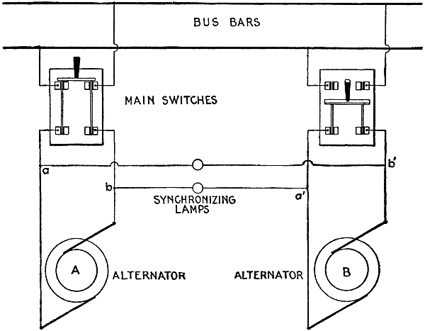
Fig. 2,847.—Brilliant lamp method of synchronizing. The synchronizing lamps are connected as shown, and must be of the alternator voltage. When the voltages are equal and the machines in phase, the difference of pressure between a and a given point is the same as that between a' and the same point; this obtains for b and b'. Accordingly, a lamp connected across a b' will burn with the same brilliancy as across a' b; the same holds for the other lamp. When the voltages are the same and the phase difference is 180° the lamps are dark, and as the phase difference is decreased, the lamps glow with increasing brightness until at synchronism they glow with maximum brilliancy. Hence the incoming alternator should be thrown in at the instant of maximum brilliancy.
Ques. What modification of the synchronizing methods shown in the accompanying illustrations is necessary when high pressure alternators are used?
Ans. Step down transformers must be used between the alternators and the lamps to obtain the proper working voltages for the lamps.
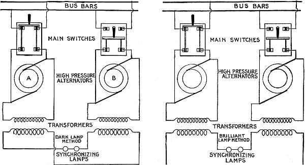
Fig. 2,848.—Synchronizing with high pressure alternators; dark and brilliant lamp methods. In both methods the primaries of the transformers are connected in the same way across the terminals of the alternators as shown. In the dark lamp method, the connections between the secondary coils of the transformers must be made so that when each is subjected to the same conditions the action of the one coil opposes that of the other as in the dark lamp method; then, if the transformers be both of the same design, there will be no voltage across the lamps when the alternators are in phase with each other. If the ratio of each transformer is such as to give, for example, 100 volts across its secondary terminals, then the two incandescent lamps since they are joined together in series must each be designed for 100 volts. One 200 volt lamp could be used in either method in place of the two 100 volt lamps. When, therefore, the alternators are directly opposite in phase to each other, both the lamps will burn brightly; as the alternators come together in phase the lamps will produce less and less light, until when the machines are exactly in phase no light will be emitted at all, at which instant the incoming alternator should be thrown in. It must be evident, if the transformer secondary connections are arranged as in the brilliant lamp method, so that they do not oppose each other, the lamps will be at maximum brilliancy when the alternators are in phase and dark when the phase difference is 180°, assuming of course equalized voltage.
Ques. How is the voltage of an incoming machine adjusted so that it will be the same as the one already in operation?
Ans. By varying the field excitation with a rheostat in the alternator field circuit.
Ques. How may two or more alternators be started simultaneously?
Ans. After bringing each of them up to its proper speed so as to obtain equal frequencies, the main switches may be closed, thereby joining their armature circuits in parallel. As yet, however, their respective field windings have not been supplied with current, so that no harm can result in doing this. The exciters of these machines after being joined in parallel, should then be made to send direct current simultaneously through the field windings of the alternators, and from this stage on the directions previously given may be followed in detail.
Ques. What are the conditions when two or more alternators are directly connected together?
Ans. If rigidly connected together, or directly connected to the same engine, they must necessarily run in the same manner at all times.
When machines connected in this way are once properly adjusted so that they are in phase with each other, their operation in parallel is even a simpler task than when they are all started together but are not directly connected.
Ques. When an alternator is driven by a gas engine, what provision is sometimes made to insure successful operation in parallel?
Ans. An amortisseur winding is provided to counteract the tendency to "hunting."
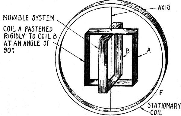
Fig. 2,849.—Diagram of Lincoln Synchronizer. In construction, a stationary coil F, has suspended within it a coil A, free to move about an axis in the planes of both coils and including a diameter of each. If an alternating current be passed through both coils, A, will take a position with its plane parallel to F. If now the currents in A and F be reversed with respect to each other, coil A will take up a position 180° from its former position. Reversal of the relative directions of currents in A and F is equivalent to changing their phase relation by 180°, and therefore this change of 180° in phase relation is followed by a corresponding change of 180° in their mechanical relation. Suppose now, instead of reversing the relative direction of currents in A and F, the change in phase relation between them be made gradually and without disturbing the current strength in either coil. It is evident that when the phase difference between A and F reaches 90°, the force between A and F will become reduced to zero, and a movable system, of which A may be made a part, is in condition to take up any position demanded by any other force. Let a second number of this movable system consist of coil B, which may be fastened rigidly to coil A, with its plane 90° from that of coil A, and the axis of A passing through diameter of B. Further, suppose a current to circulate through B, whose difference in phase relation to that in A, is always 90°. It is evident under these conditions that when the difference in phase between A and F is 90°, the movable system will take up a position, such that B is parallel to F, because the force between A and F is zero, and the force between B and F is a maximum; similarly when the difference in phase between B and F is 90°, A will be parallel to F. That is, beginning with a phase difference between A and F of zero a phase change of 90° will be followed by a mechanical change on a movable system of 90°, and each successive change of 90° in phase will be followed by a corresponding mechanical change of 90°. For intermediate phase relation, it can be proved that under certain conditions the position of equilibrium assumed by the movable element will exactly represent the phase relations. That is, with proper design, the mechanical angle between the plane of F and that of A and also between the plane of F and that of B, is always equal to the phase angle between the current flowing in F and those in A and B respectively. As commercially constructed coil F consists of a small laminated iron field magnet with a winding whose terminals are connected with binding posts. The coils A and B are windings practically 90° apart on a laminated iron armature pivoted between the poles of the magnet. These two windings are joined, and a tap from the junction is brought out through a slip ring to one of two other binding posts. The two remaining ends are brought out through two more slip rings, one of which is connected to the remaining binding post, through a non-inductive resistance, and the other to the same binding post through an inductive resistance. A light aluminum hand attached to the armature shaft marks the position assumed by the armature.
Ques. What is the action of the amortisseur winding?
Ans. Any sudden change in the speed of the field, generates a current in the amortisseur winding which resists the change of velocity that caused the current.
The appearance of an amortisseur winding is shown in the cut below (fig. 2,850) illustrating the field of a synchronous condenser equipped with amortisseur winding.
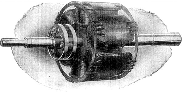
Fig. 2,850.—General Electric field of synchronous condenser provided with amortisseur winding. Hunting is accompanied by a shifting of flux across the face of the pole pieces due to the variation in the effect of armature reaction on the main field flux as the current varies and the angular displacement between the field and armature poles is changed. Copper short circuited collars placed around the pole face have currents induced in them by this shifting flux, which have such a direction as to exert a torque tending to oppose any change in the relative position of the field and armature. This action is similar to that of the running torque of an induction motor and the damping device has been still further developed until in its best form it resembles the armature winding of a "squirrel cage" induction motor. The pole pieces are in ducts, and low resistance copper bars placed in them with their ends joined by means of a continuous short circuiting ring extending around the field. Such a device has proven very effective in damping out oscillations started from any cause, the same winding doing duty as a damping device and to assist the starting characteristics.
Ques. How are three phase alternators synchronized?
Ans. In a manner similar to the single phase method.
Thus the synchronizing lamps may be arranged as in fig. 2,581, which is simply an extension of the single phase method.
Ques. Are three lamps necessary?
Ans. Only to insure that the connections are properly made, after which one lamp is all that is required.
Ques. How is it known that the connections of fig. 2,851 are correct?
Ans. If, in operation, the three lamps become bright or dark simultaneously, the connections are correct; if this action takes place successively, the connections are wrong.
If wrong, transpose the leads of one machine until simultaneous action of the lamps is secured.
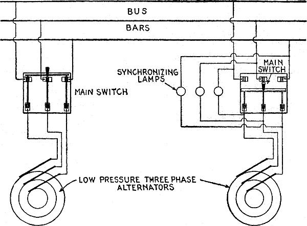
Fig. 2,851.—Method of synchronizing three phase alternators with, three lamps, being an extension of the single phase method.
Ques. What is the disadvantage of the lamp method of synchronizing?
Ans. Lack of sensitiveness.
Ques. Which is the accepted lamp method, dark or brilliant?
Ans. In the United States it is usual to make the connections for a dark lamp at synchronism, while in England the opposite practice obtains.
With the dark lamp method, the breaking of a filament might cause the machines to be connected with a great phase difference, whereas, with the brilliant lamp it is difficult to determine the point of maximum brilliancy. This latter method, therefore may be called the safer.
Ques. What may be used in place of lamps for synchronizing?
Ans. Some form of synchroscopes, or synchronizers.
Ques. How does the Lincoln synchronizer work?
Ans. The construction is such that a hand moves around a dial so that the angle between the hand and the vertical is always the phase angle between the two sources of electric pressure to which the synchronizer is connected.
If the incoming alternator be running too slow, the hand deflects in one direction, if too fast, in the other direction. When the hand shows no deflection, that is, when it stands vertical, the machines are in phase. A complete revolution of the hand indicates a gain or loss of one cycle in the frequency of the incoming machine, as referred to the bus bars.
Cutting Out Alternator.—When it is desired to cut out of circuit an alternator running in parallel with others, the method of procedure is as follows:
1. Reduce driving power until the load has been transferred to the other alternators, adjusting field rheostat to obtain minimum current;
2. Open main switch;
3. Open field switch.
Ques. What precaution should be taken?
Ans. Never open field switch before main switch.
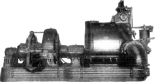
Fig. 2,852.—General Electric 500 kw., horizontal mixed pressure Curtis turbine connected to a 500 kw. dynamo. In a Curtis turbine it is not necessary to use the whole periphery of the first stage for low pressure steam nozzles. A section can be partitioned off and equipped with special expanding nozzles to receive steam at high pressure direct from the boilers. Such nozzles deliver their steam against the same wheel as do the low pressure nozzles, but occupy only a small portion of its periphery. The steam is expanded in these nozzles from high pressure all the way down to the normal pressure of the first stage, and in such expansion acquires a high velocity and consequently contains a great deal of energy—much more than does an equal quantity of low pressure steam. In consequence of this, high pressure steam is used with a far lower water rate than is obtained with low pressure steam, or with high pressure steam reduced to low pressure in a reducing valve. This construction is called "mixed pressure." Its function is the same as that of the reducing valve, that is, it makes up for a deficiency of low pressure steam by drawing direct on the boilers. With this construction, the full power of the turbine can be developed with: All low-pressure steam, all high pressure steam, or, any necessary proportion of steam of each pressure. Furthermore, the transition from all low pressure to all high pressure, through all the conditions intermediate between these extremes, is provided for automatically by the turbine governor; a deficiency of low pressure steam causes the high pressure nozzles to open automatically.
Ques. What is the ordinary method of cutting out an alternator?
Ans. The main switch is usually opened without any preliminaries.
Ques. What is the objection to this procedure?
Ans. It suddenly throws all the load on the other alternators, and causes "hunting."
Ques. What forms of drive are especially desirable for running alternators in parallel, and why?
Ans. Water turbine or steam turbine because of the uniform torque, thus giving uniform motion of rotation.
With reciprocating engines, the crank effect is very variable during the revolution, resulting in pulsations driving the alternator too fast or too slow, and causing cross current between the alternators.
Ques. Is a sluggish, or a too sensitive governor preferable on an engine driving alternators in parallel?
Ans. A sluggish governor.
Alternators in Series.—Alternators are seldom if ever connected in series, for the reason that the synchronizing tendency peculiar to these machines causes them to oppose each other and fall out of phase when they are joined together in this way. If, however, they be directly connected to each other, or to an engine, so that they necessarily keep in phase at all times, and thus add their respective voltages instead of counteracting them, series operation is possible.
NOTE.—According to the practice of the General Electric Co., 2½ degrees of phase difference from a mean is the limit allowable in ordinary cases. It will, in certain cases, be possible to operate satisfactorily in parallel, or to run synchronous apparatus from machines whose angular variation exceeds this amount, and in other cases it will be easy and desirable to obtain a better speed control. The 2½ degree limit is intended to imply that the maximum departure from the mean position during any revolution shall not exceed 2½ ÷ 360 of an angle corresponding to two poles of a machine. The angle of circumference which corresponds to the 2½ degree of phase variation can be ascertained by dividing 2½ by ½ the number of pole; thus, in a 20 pole machine, the allowable angular variation from the mean would be 2½ ÷ 10 = ¼ of one degree.
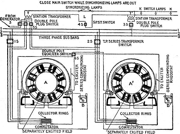
Fig. 2,853.—Diagram of connections for synchronizing two compound wound three phase alternators. A and A' are the armatures of the two machines, the fields of which are partly separately excited, the amount of excitation current being controlled by the series compounding rheostats B and B', which form a stationary shunt. It is assumed that the alternator A is connected to the bus bars 1, 2, and 3, by the switch 1S. If an increase make it necessary to introduce the alternator A', it is first run up to speed and excited to standard pressure by its exciter, and then the double plug switch 3S is closed, connecting the primary of the station transformer T and T' with the bus bars through the secondary coil, so that the synchronizing lamps light up when the secondary circuit is closed through the single pole switch 4S. The primary of the station transformer T is thus excited through the double pole switch 5S, connecting it with the outer terminals of the armature A'. The two alternators will now work in opposition to each other upon the synchronizing lamps, the transformer T being operated by the new alternator A' through the switch 2S, and the transformer T' being operated by the working alternator A, from the bus bars. If the new alternator be not in step with the working alternator, the synchronizing lamps will glow, growing brighter and dimmer alternately with greater or lesser rapidity. In this case, the armature speed of the new alternator must be controlled in such a manner that the brightening and dimming will occur more and more slowly, until the lamps cease to glow or remain extinguished for a decided interval of time. The extinction of the light is due to the disappearance of the secondary current, and indicates that the alternators are in step. The switch 2S should now be thrown, thus coupling the two machines electrically, and both of them will continue to operate in step. The double pole equalizer switch 6S should now be closed, connecting the two field windings in parallel and equalizing the compounding, so that any variations of load will affect the two alternators equally. After the alternators have been connected in parallel, the switches 4S and 5S, may be opened leaving the switch 3S closed, to operate the switchboard lamps K, K, as pilot lights from the bus bars.