Chapter LXVI · POWER STATIONS (continued 2)
Reading edition
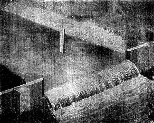
Fig. 2,759.—Illustration of a weir. To make a weir, place a board across the stream at some point which will allow a pond to form above. The board should have a notch cut in it with both side edges and the bottom sharply beveled toward the intake, as shown in the above cut. The bottom of the notch, which is called the "crest" of the weir, should be perfectly level and the sides vertical. In the pond back of the weir, at a distance not less than the length of the notch, drive a stake near the bank, with its top precisely level with the crest. By means of a rule, or a graduated stake as shown, measure the depth of water over the top of stake, making allowance for capillary attraction of the water against the sides of the weir. For extreme accuracy this depth may be measured to thousandths of a foot by means of a "hook gauge," familiar to all engineers. Having ascertained the depth of water over the stake, refer to the accompanying table, from which may be calculated the amount of water flowing over the weir. There are certain proportions which must be observed in the dimensions of this notch. Its length, or width, should be between four and eight times the depth of water flowing over the crest of the weir. The pond back of the weir should be at least fifty per cent. wider than the notch and of sufficient width and depth that the velocity of flow or approach be not over one foot per second. In order to obtain these results it is advisable to experiment to some extent.
Speed regulation is effected by varying the number of nozzles in flow, that is, for light loads fewer nozzles are open and a smaller volume of steam is admitted to the turbine wheel, but the steam that is admitted impinges against the moving blades with the same velocity always, no matter whether the volume be large or small. With a full load and all the nozzle sections in flow, the steam passes to the wheel in a broad belt and steady flow.
WEIR TABLE
giving cubic feet of water per minute that will flow over a weir one inch wide and from ⅛ to 20⅞ inches deep.
Depth inches ⅛ ¼ ⅜ ½ ⅝ ¾ ⅞
0 .00 .01 .05 .09 .14 .19 .26 .32
1 .40 .47 .55 .64 .73 .82 .92 1.02
2 1.13 1.23 1.35 1.36 1.58 1.70 1.82 1.95
3 2.07 2.21 2.34 2.48 2.61 2.76 2.90 3.05
4 3.20 3.35 3.50 3.66 3.81 3.97 4.14 4.30
5 4.47 4.64 4.81 4.98 5.15 5.33 5.51 5.69
6 5.87 6.06 6.25 6.44 6.62 6.82 7.01 7.21
7 7.40 7.60 7.80 8.01 8.21 8.42 8.63 8.83
8 9.05 9.26 9.47 9.69 9.91 10.13 10.35 10.57
9 10.80 11.02 11.25 11.48 11.71 11.94 12.17 12.41
10 12.64 12.88 13.12 13.36 13.60 13.85 14.09 14.34
11 14.59 14.84 15.09 15.34 15.59 15.85 16.11 16.36
12 16.62 16.88 17.15 17.41 17.67 17.94 18.21 18.47
13 18.74 19.01 19.29 19.56 19.84 20.11 20.39 20.67
14 20.95 21.23 21.51 21.80 22.08 22.37 22.65 22.94
15 23.23 23.52 23.82 24.11 24.40 24.70 25.00 25.30
16 25.60 25.90 26.20 26.50 26.80 27.11 27.42 27.72
17 28.03 28.34 28.65 28.97 29.28 29.59 29.91 30.22
18 30.54 30.86 31.18 31.50 31.82 32.15 32.47 32.80
19 33.12 33.45 33.78 34.11 34.44 34.77 35.10 35.44
20 35.77 36.11 36.45 36.78 37.12 37.46 37.80 38.15
NOTE.—The weir table on this page contains figures 1, 2, 3, etc., in the first vertical column which indicates the inches depth of water running over weir board notches. Frequently the depths measured represent also fractional inches, between 1 and 2, 2 and 3, etc. The horizontal line of fraction at the top represents these fractional parts, and can be applied between any of the numbers of inches depth, from 1 to 25. The body of the table shows the cubic feet, and the fractional parts of a cubic foot, which will pass each minute for each inch in depth, and for each fractional part of an inch by eighths for all depths from 1 to 25 inches. Each of these results is for only one inch width of weir. To estimate for any width of weir the result obtained for one inch width must be multiplied by the number of inches constituting the whole horizontal length of weir.
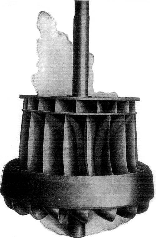
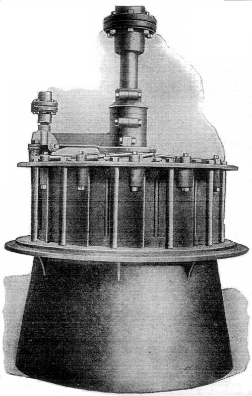
Figs. 2,760 and 2,761.—Samson vertical runner and shaft, and complete Samson vertical turbine. The runner is composed of two separate and distinct types of wheel, having thereby also two diameters. Each wheel or set of buckets receives its separate quantity of water from one and the same set of guides, but each set acts only once and singly upon the water used, and the water does not act twice upon the combined wheel, as some suppose. In construction, the lower or main set of buckets is made of flanged plate steel, and cast solidly into a heavy ring surrounding the outer and lower edges, and into a heavy diaphragm, separating the two sets of buckets.
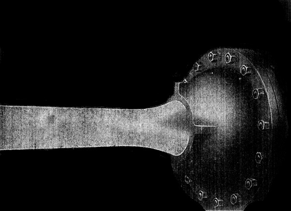
Fig. 2,762.—Water discharging from a needle nozzle due to a pressure of 169 lbs. per sq. in.
Hydro-Electric Plants.—The economy with which electricity can be transmitted long distances by high tension alternating currents, has led to the development of a large number of water powers in more or less remote regions.
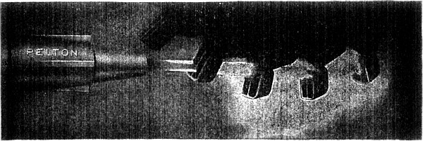
Fig. 2,763.—Photograph of an operating tangential water wheel equipped with Pelton buckets.
This economy is possible by the facility with which alternating current can be transformed up and down. Thus at the hydro-electro plant, the current generated by the water wheel driven alternator is transformed to very high pressure and transmitted with economy a long distance to the distributing point where it is transformed down to the proper pressure for distribution.
A water wheel or turbine is a machine in which a rotary motion is obtained by transference of the momentum of water; broadly speaking, the fluid is guided by fixed blades, attached with a casing, and impinging on other blades mounted on a drum or shaft, causing the latter to revolve.
There are two general classes of turbine: 1. Impulse turbines; 2. Reaction turbines.
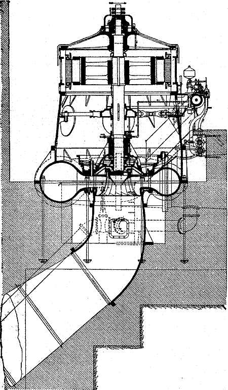
Fig. 2,764.—Sectional elevation of one of the 5,000 horse power vertical Pelton-Francis turbines directly connected to generator, as installed for the Schenectady Power Co.
Ques. What is an impulse turbine?
Ans. One in which the fluid is directed by means of a series of nozzles against vanes which it drives.
Ques. What is a reaction turbine?
Ans. One in which the pressure or head of the water is employed rather than its velocity. The current is deflected upon the wheel by the action of suitably disposed guide blades, the passages being full of water. Rotary motion is obtained by the change in the direction and momentum of the fluid.
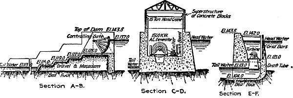
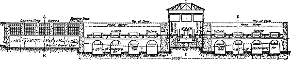
Figs. 2,765 to 2,768.—Cross sections of Lowel dam power house, and wheel pits containing sixteen Samson turbines: The section C-D gives an end view of the generator room showing the locations of the generators below the head level water. They are secure against flood water, or leakage, by well constructed stuffing boxes in the iron bulkheads, through which the turbine wheel shafts pass and connect to the generators. Section E-F gives an end view of one of these wheel rooms or penstocks, and shows the extension of the draft tube from wheel case into tail water. The section A-B shows the sub-structure of gravel and macadam under the controlling gates, this forming also a portion or extension of the dam proper. These gates turn on an axis made of two 15 inch I beams securely riveted together with plates and angle irons to which the wooden frame is attached. The radius of the gates is 14 feet. They are designed to allow the water to pass underneath the gate, thus controlling any height of head water. They are intended to take care of an excess of water at unusual stages of the river. The whole affair has been well designed and executed. This plant furnishes a good example of a secure, and level foundation, since the wheel houses and generator room are immediately on the rock. It is necessary in all tandem plants to provide a very secure, substantial super-structure so that the long line of turbines and shaft will always remain straight and in proper alignment with the generator and the turbine cases. Users cannot be reminded of this too often.
Ques. Name three classes of reaction turbines.
Ans. Parallel flow, inward flow, and outward flow.
Parallel flow turbines have an efficiency of about 70% and are suited for low falls not over 30 feet. Inward and outward flow turbines have an efficiency of about 85%. Impulse turbines are suitable for high heads.
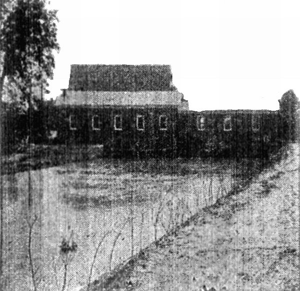
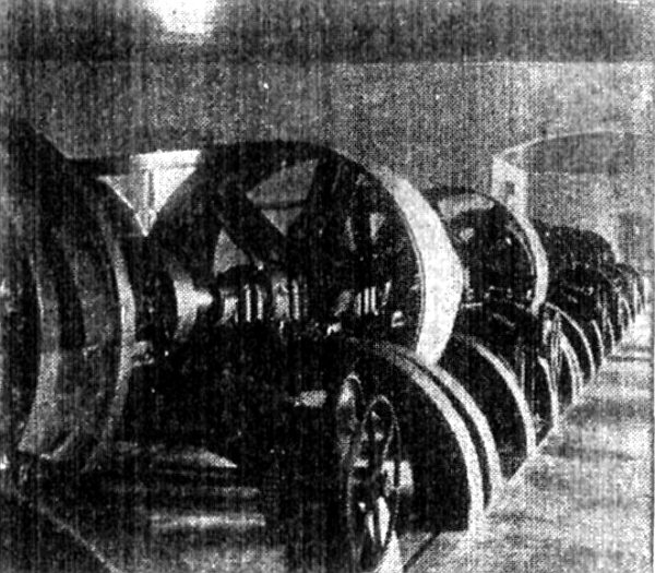
Figs. 2,769 and 2,770.—Exterior and interior of hydro-electric plant at Harrisburg, Va. It is located on the south fork of the Shenandoah River, twelve and one-half miles distant. A dam 720 feet long and 15 feet high was built on a limestone ledge running across the river; which with a fall of 5 feet from the dam to the power house, a quarter of a mile distant, secured an effective head pressure of 20 feet. The power house, comprising the generator room and the wheel room, also the machinery room, are here shown. The wheel room, which is 20 × 40 feet, extends across the head race, and rests upon solid concrete walls, forming the sides and ends of the wheel pits. The end wall is 6 feet thick at the bottom, and 4½ feet at the top. It has three arched openings, each 8 feet wide and 9 feet high, through which the water escapes after leaving the turbines. The intake is protected by a wrought iron rack 40 feet long. The power is obtained by three 50 inch vertical shaft Samson turbines, with a 20 inch Samson for an exciter. The three large turbines have a rating of 1,350 horse power; and are connected to the main horizontal line shaft by bevel mortise gears 7 feet diameter and 15 inches face. The couplings on the main shaft have 48 inch friction clutch hubs, permitting either or each turbine being operated, or shut down independently of the others. The main shaft is 85 feet long and 6 inches diameter; making 280 revolutions. This shaft carries two pulleys 70 inches diameter and 38 inches face for driving the generators. The accompanying illustration shows the harness work, gears, pulleys, etc., furnished with the turbines. The 20 inch horizontal shaft Samson turbine of 72 horse power is direct connected to an exciter generator of 20 kw., running 700 rev. per min. The two large generators are driven 450 revolutions per minute by belts producing a three phase current of 60 cycles of 11,500 volts for the twelve and one-half miles transmission. The line consists of three strands of No. 4 bare copper wire. This current is used for lighting and power purposes, and the plant is of the latest improved design and construction.
Isolated Plants.—When electric power transmission from central stations first came into commercial use, the distance from the station at which current could be obtained at a reasonable cost was exceedingly limited.
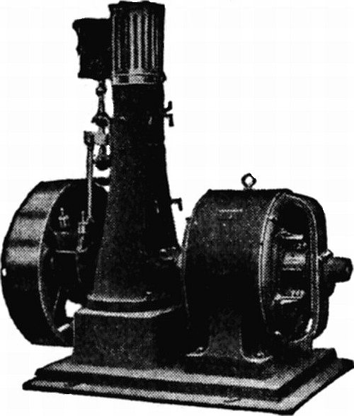
Fig. 2,769a.—Triumph direct current generator set with upright slide valve engine.
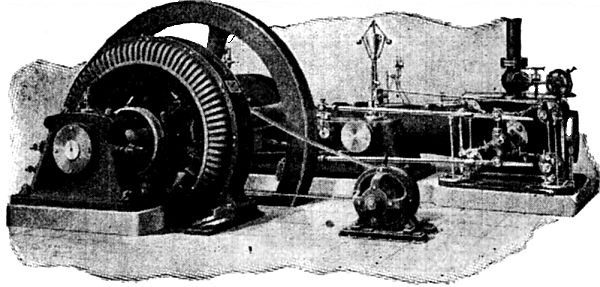
Fig. 2,770a.—Murray alternating current direct connected unit with high speed Corliss engine and belt driven exciter, 50, 75 and 100 kva. alternator and 150 R.P.M. engine.
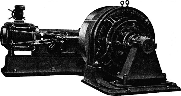
Fig. 2,771.—Direct connected direct current unit with Ridgway high speed four valve engine.
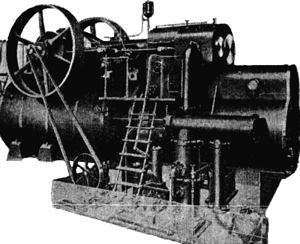
Fig. 2,772.—Buckeye mobile, or self contained unit consisting of compound condensing engine, boiler, superheater, reheater, feed and air pumps; it produces one horse power on 1½ lbs. of coal, built in sizes from 75 to 600 horse power.
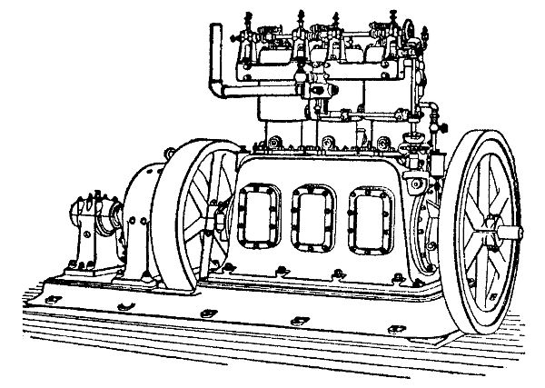
Fig. 2,773.—Westinghouse three cylinder gas engine, direct connected to dynamo, showing application of gas engine drive for small direct connected units.
Consequently, persons desiring electrical power were in the majority of cases forced to install their own apparatus for producing it, this being the origin of isolated plants.
From the nature of the case it is evident that an isolated plant is as a rule smaller and more simple in construction than a central station, and in consequence much more readily operated and managed. It is generally owned by a private individual or a corporation and operated in conjunction with other affairs of a similar character. A basement or other portion of a building is usually set aside in which the necessary apparatus is installed.
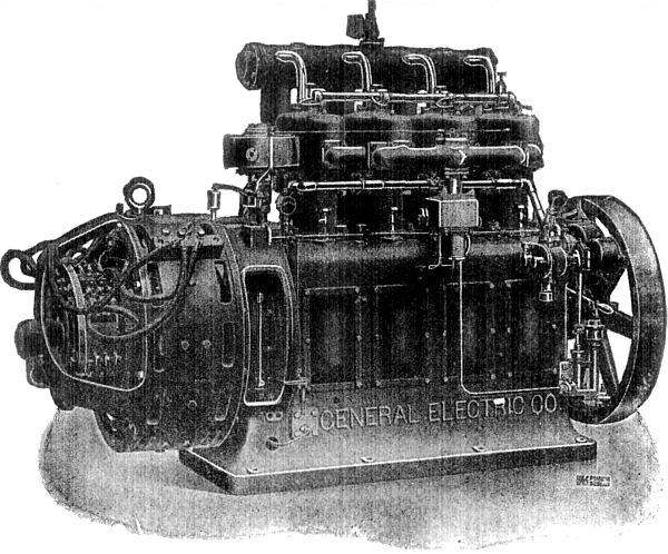
Fig. 2,774.—General Electric 25 kw., gasoline electric generating set for lighting and power. The engine has four cylinders 7¼ × 7½, and runs at a speed of 560 revolutions per minute. The total candle power capacity in Mazda lamps is 20,000. The ignition is by low tension magneto, coil and battery. Carburetter is of the constant level type to which gasoline is delivered by a pump driven by the engine. Forced lubrication; five crank shaft bearings babbitted; valves in side; overall dimensions 96 × 34 × 60 high; weight 5,000.
Although electricity is now transmitted economically to great distances from central stations, there is still a field for the isolated plant.
The average type of isolated plant has enlarged from a small dynamo driven by a little slide valve engine located in an out of the way corner to direct connected generators and engines of hundreds and even thousands of horse power assembled in a large room specially adapted to the purpose.
In the more modern of these, the electrical outputs are each frequently equal to that of a town central station of respectable size, and the auxiliary equipments are similar in every particular. As a matter of fact, in certain modern isolated plants the only feature that distinguishes them from central stations is that in the former case the owner of the plant represents the sole consumer and conducts other business in connection with it, whereas in the latter case there are a large number of consumers uninterested financially in the enterprise, which is itself generally owned and operated by a company conducting no other business.
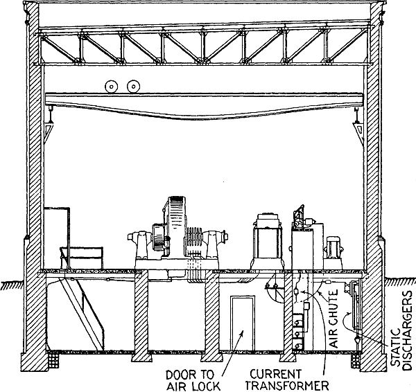
Fig. 2,775.—Plan of sub-station with air blast transformers and motor operated oil switches and underground 11,000 or 13,200 volt high tension lines.
Sub-Stations.—According to the usual meaning of the term, a sub-station is a building provided with apparatus for changing high pressure alternating current received from the central station into direct current of the requisite pressure, which in the case of railways is 550 to 600 volts.
Where traffic is heavy and the railway system of considerable distance, sub-stations are provided at intervals along the line, each receiving high pressure current from one large central station and converting it into moderate pressure direct current for their districts.
Ques. Upon what does the arrangement of the sub-station depend?
Ans. Upon the character of the work and the type of apparatus employed for converting the high pressure alternating current into direct current.
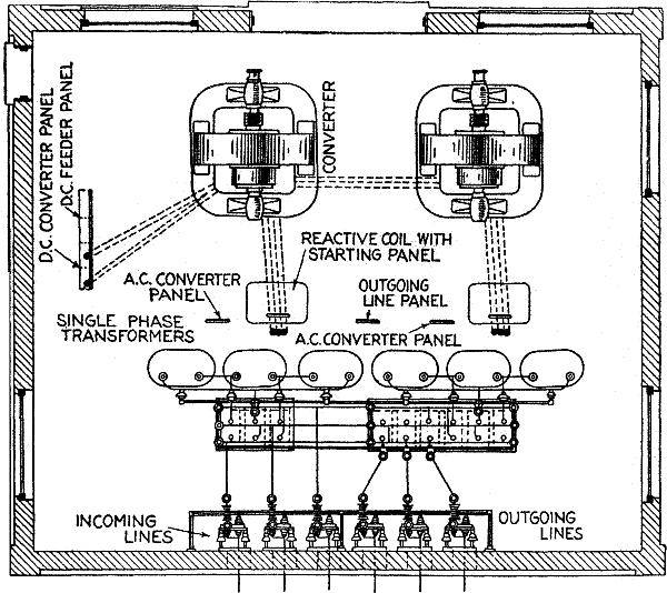
Fig. 2,776.—Plan of small sub-station with single phase oil insulated self-cooling transformers and hand operated oil switches 11,000 or 13,200 volts, overhead high tension lines.
In general it should be substantial, convenient to install or replace the heavy machines, and the layout arranged so that the apparatus can be readily operated by those in attendance.
An overhead traveling crane is the most convenient method of handling the heavy machinery, and is frequently used in large sub-stations.
Fig. 2,776 shows a sectional view, and fig. 2,777, a plan for a small sub-station containing two rotary converters and two banks of three single phase static transformers operating on a three phase system at 11,000 or 13,200 volts, together with the auxiliary apparatus.
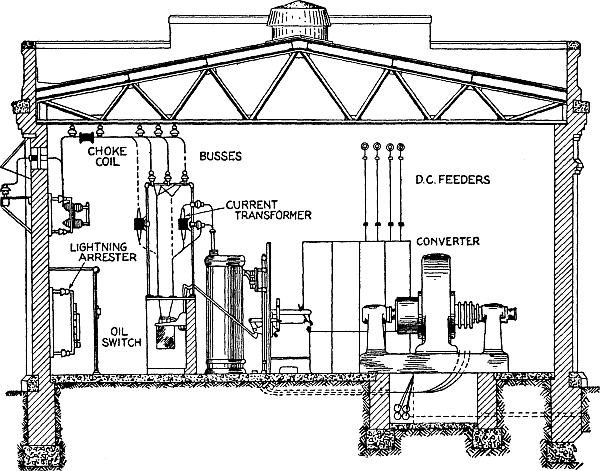
Fig. 2,777.—Elevation of small sub-station, as shown in plan in Fig. 2,776.
Ques. For three phase installations, what are the merits of separate and combined transformers?
Ans. With separate transformer for each phase, repairs are more readily made in case of accident or burnouts in the coils. The three phase units have the advantage of low first cost.
Sub-station transformers produce considerable heat, due to the hysteresis and eddy currents, and it is necessary to get rid of it.
Small transformers radiate the heat from the shell and the medium sizes have corrugated shells which increase the surface and provide more rapid radiation.
Large transformers are cooled by an air blast supplied by motor driven blowers or by water pumped through a coil of pipe which is immersed in the insulating oil of the transformer. The large size oil insulated, water cooled transformers are used on circuits of 33,000 volts or more. In water turbine plants, the water may be piped to the transformer under pressure and the pump omitted which cuts down the cost of operating. Air blast transformers usually have a damper or shutter for air control.
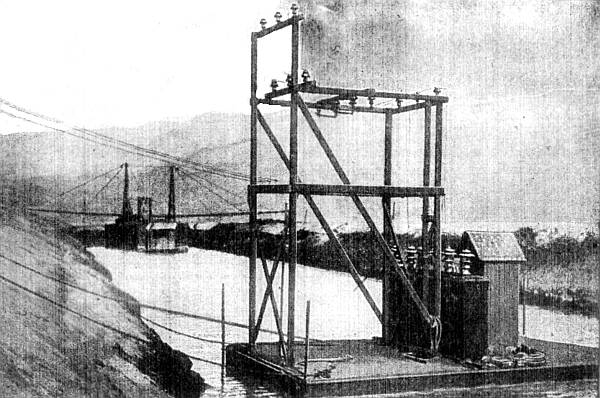
Fig. 2,778.—Marine portable transformer station on Los Angeles Aqueduct. The view shows three 20 kva. Westinghouse out door transformers installed on a float, 33,000 volts high pressure; 440 volts low pressure; 50 cycles.
Ques. Explain the use of reactance coils in sub-stations.
Ans. In order that the direct current voltage of the ordinary rotary may be regulated by a field rheostat, which calls for a corresponding change in the alternating current voltage, a reactance coil is provided between the low tension winding and the converter.
Without such a reactance the maintenance of the same voltage at full load as at no load involves excessive leading and lagging currents and consequently excessive heating in the armature inductors, unless the resistance drop from the source of constant pressure is small, or the natural reactance of the circuit high.
Ques. What is the effect of weakening the converter field?
Ans. A lagging current is set up which causes a drop in the reactance coil.
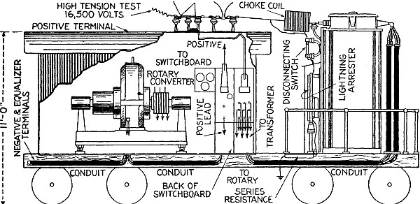
Fig. 2,779.—Sectional elevation of portable outdoor transformer type sub-station. The high voltage switching and protective apparatus is mounted, out of the way, on the roof of the car, but is operated from the switchboard with a standard remote control handle. The transformer is carried directly over the truck at the uncovered end of the car and the low-tension leads from it run in conduit beneath the floor and up into the cab, (which contains the converter and switchboard) to the converter. The positive lead runs through a conduit and ends in a terminal on the roof. The energy thus makes a complete circuit of the car leaving at a point close to that at which it entered. The low pressure alternating current as well as the direct current positive leads are carried below the car floor in iron conduit supported from the channel frame. The field wires are carried through this conduit to the rheostat. Wiring for the lights is arranged to supply two, 5 light clusters. One is fed with the 600 volt direct current and the other with 420 volt alternating current. All lighting conductors are carried in metal moulding carried between the flanges of the channel iron ribs. High wiring is carried entirely on the roof of the car where it is entirely out of the way and where the operator cannot come in contact with it. The switchboard should be of the utmost simplicity. Usually the negative and equalizer switches, and the field break-up switch are mounted on the frame of the converter. The double throw switch for starting and running the converter can be mounted under the floor of the car and operated by handle at the switchboard. The rheostat can be mounted back of the switchboard on brackets bolted to the car super-structure. The switchboard need only carry the positive knife switch and circuit breaker, and the alternating current ammeter, voltmeter and power factor meter. Sometimes a watthour meter is added. The positive lead is brought out through a conduit on the roof of the car and is arranged for bolting to the positive feeder. The negative and equalizer terminals are located at the cab end of the car and are arranged so that connection can be easily made from them to the ground and, if necessary, to an equalizer circuit. There is usually a sliding door at each end of the cab and two windows on each side. Above the doors, transoms, extending the width of the cab, are arranged to drop so that a current of air will circulate through the cab under the roof, carrying out the heated air. There are also several ventilating holes beneath the converter in the floor of the car. These provisions insure a constant circulation of air through the car which carries away all heated air.
Ques. State the effect of strengthening converter field.
Ans. A leading current is set up which gives a rise of voltage in the reactance coil.
Hence when a heavy current passes through the series coil of a compound wound converter and tends to produce a leading current, the reactance coil will balance it, and improve the power factor of the whole line.
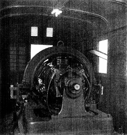
Fig. 2,780.—Westinghouse 300 kw. converter in portable sub-station.
Portable Sub-Stations.—A portable sub-station constitutes a spare equipment for practically any number of permanent sub-stations and renders unnecessary the installation of spare equipment in each.
It can be used to increase the capacity of a permanent sub-station when the load is unusually heavy, or to provide service while a permanent sub-station is being overhauled or rebuilt.
The transformer can be used for emergency lighting, the primary being connected to a high pressure line and the secondary to the load, if special provision be made at the time the transformer is built to adapt it for these applications.
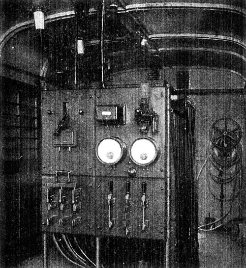
Fig. 2,781.—Switchboard end of Westinghouse portable sub-station.
When an electric railway has a portable sub-station, direct current can be provided at any point on the system where there is track at the high pressure line. The direct current can be made available very quickly as its production involves only the transferring of the sub-station, and its connection to the high pressure line.
Portable sub-stations range in capacity from 200 to 500 kw., and for all alternating current voltages up to 66,000, and frequencies of 25 and 60 cycles.
Although portable sub-stations usually must be of more or less special design to adapt them to the conditions under which they must operate, there are certain general features that are common to all. All members are readily accessible and there are no unnecessary parts. The weight and dimensions are a minimum insuring ease of transportation. Live parts are so protected that the danger of accidental contact with them is minimized.
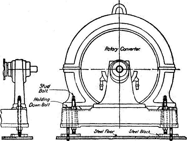
Figs. 2,782 and 2,783.—Views of levelling device for Westinghouse converter.
Ques. What are the advantages of using outdoor transformers on portable sub-stations?
Ans. All high pressure wiring is kept out of the car. The transformer is more effectively cooled and the heat dissipated by the transformer does not warm the interior of the cab. The transformer is much more accessible. The car can be run under a crane and the transformer coils pulled out with a hoist.
Taps for different high and low pressure voltages can be readily provided at the time the transformer is being built.