Chapter LXVII · MANAGEMENT (continued 2)
Reading edition
Transformers.—These, as a whole, are simple in construction, high in efficiency, and comparatively inexpensive. Their principles of operation are also readily understood.
The efficiency of a transformer, that is, the ratio between full load primary and full load secondary is greatest when the load on it is such that the sum of the constant losses equals the sum of the variable losses.
In general, transformers designed for high frequencies and large capacities are more efficient than those designed for low frequencies and small capacities. As a whole, however, a transformer leaves but little to be desired as regards efficiency, a modern 60 cycle transformer of 50 kilowatts capacity or more possesses an efficiency of approximately 98 per cent. at full load and an efficiency of about 97 per cent. at half load.
Ques. How should a transformer be selected, with respect to efficiency?
Ans. One should be chosen, whose parts are so proportioned that the point of maximum efficiency occurs at that load which the transformer usually carries in service.
In many alternating current installations, comparatively light loads are carried the greater part of the time, the rated full load or an overload being occurrences of short durations. For such purposes special attention should be given to the designing or selecting of transformers having low core losses rather than low resistance losses, because the latter are then of relatively small importance.
Ques. What kind of efficiency is the station manager interested in?
Ans. The "all day efficiency."
This expression, as commonly met with in practice, denotes the percentage that the amount of energy actually used by the consumer is of the total energy supplied to his transformer during 24 hours. The formula for calculating the all day efficiency of a transformer is based upon the supposition that the amount of energy used by the consumer during 24 hours is equivalent to full load on his transformer during five hours and is as follows:
5w
E = ——————
24c + 5r + 5w
where
E = the all day efficiency of the transformer,
w = the full load in watts on the primary,
c = the core loss in watts,
r = the resistance loss in watts.
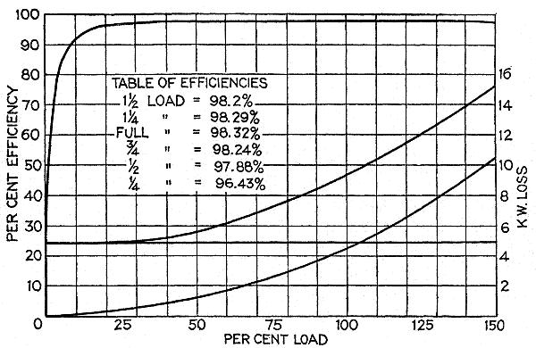
Fig. 2,854.—Performance curves of Westinghouse air blast 550 kw, 10,500 volt transformer, 3,000 alternations.
Ques. What are the usual all day efficiencies?
Ans. The average is about 85 per cent. for those of 1 kilowatt capacity, 92 per cent. for those of 5 kilowatts capacity, 94 per cent. for those of 10 kilowatts capacity, and about 94.5 per cent. for those of 15 kilowatts capacity.
Ques. What becomes of the energy lost by a transformer?
Ans. It reappears as heat in the windings and core.
This heat not only increases the resistances of the windings and core, producing thereby a further increase of their respective losses, but in addition causes in time a peculiar effect on the iron core which is intensified by the reversals of magnetism constantly going on within it.
After about two years' service, the iron apparently becomes fatigued or tired, and this phenomenon is called aging of the iron. Since the life of the transformer depends to a great extent upon this factor, the conditions responsible for its existence should as far as possible be removed. Means must therefore be provided in the construction to radiate the heat as quickly as it is generated.
Ques. What kind of oil is used in oil cooled transformers?
Ans. Mineral oil.
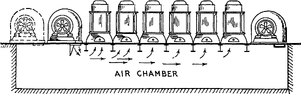
Fig. 2,855.—General arrangement of air blast transformers and blowers.
Ques. How is it obtained?
Ans. By fractional distillations of petroleum unmixed with any other substances and without subsequent chemical treatment.
Ques. What is the important requirement for transformer oil?
Ans. It should be free from moisture, acid, alkali or sulphur compounds.
Ques. How may the presence of moisture be determined?
Ans. By thrusting a red hot iron rod in the oil; if it "crackle," moisture is present.
Ques. Describe the Westinghouse method of drying oil.
Ans. It is circulated through a tank containing lime, and afterwards, through a dry sand filter.
Ques. What is the objection to heating the oil (raising its temperature slightly above boiling point of water) to remove the moisture?
Ans. The time consumed (several days) is excessive.
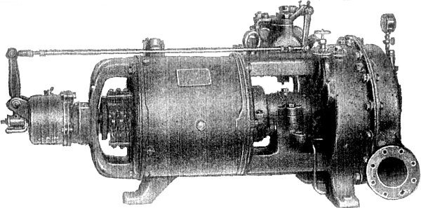
Fig. 2,856.—Small Curtis turbine generator set as made by the General Electric Co., in sizes from 5 kw., to 300 kw. It can be arranged to operate either condensing or non-condensing, and at any steam pressure above 80 lbs. for the smaller sizes and 100 lbs. for the larger. There are only two main bearings. A thrust bearing, consisting of roller bearings and running between hardened steel face washers located at either end of the main bearings is provided solely for centering the rotor so as to equalize the clearance. A centrifugal governor is provided (in the smaller sizes) completely housed, and mounted directly on the main shaft end. It controls a balanced poppet valve through a bell crank. In the larger sizes (75 kw. and above) the governor is mounted on a vertical secondary shaft geared to the main shaft and controls a cam shaft which opens or closes a series of valves in rotation, admitting the steam to different sections of the first stage nozzles. In this way throttling of the steam is avoided. There is also an emergency governor which closes the throttle valve in the event of the speed reaching a predetermined limit. The speeds of operation range from 5,000 R.P.M. for the smallest size to 1,500 R.P.M. for the largest. The lubrication system is enclosed and is automatic. Air leakage where the shaft passes through the wheel casing is prevented by steam seal.
Ques. What effect has moisture?
Ans. It reduces the insulation value of the oil. .06 per cent. of moisture has been found to reduce the dielectric strength of oil about 50 per cent. "dry" oil will withstand a pressure of 25,000 volts between two 9½ inch knobs separated .15 inch.
Ques. What is understood by transformer regulation?
Ans. It is the difference between the secondary voltage at no load and at full load, and is generally expressed as a percentage of the secondary voltage at no load.
Ques. What governs its value?
Ans. The resistance and reactance of the windings.
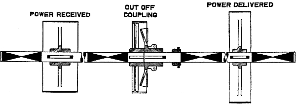
Fig. 2,857.—Cut off coupling for power transmission by line shafting. It is used to cut off a driving shaft from a driven shaft. Its use obviates the use of a quill, such as is shown in fig. 2,858.
Ques. How may the regulation be improved?
Ans. By decreasing the resistances of the windings by employing conductors of greater cross section, or decreasing their reactance by dividing the coils into sections and closely interspersing those of the primary between those of the secondary.
NOTE.—The term "regulation" as here used is synonymous with "drop." The voltage drop in a transformer denotes the drop of voltage occurring across the secondary terminals of a transformer with load. This drop is due to two causes: 1, the resistance of the windings; and 2, the reactance or magnetic leakage of the windings. On non-inductive load, the reactive drop, being in quadrature, produces but a slight effect, but on inductive loads it causes the voltage to drop, and on leading current loads it causes the voltage to rise. As the voltage drop of a good transformer is very small even on inductive load, direct accurate measurement is difficult. It is best to measure the copper loss with short circuited secondary by means of a wattmeter, and at the same time the voltage required to drive full load current through. From the watts, the resistance drop can be found, and from this and the impedance voltage, the reactive drop may be calculated. From these data a simple vector diagram will give, near enough for all practical purposes, the drop for any power factor, or the following formula may be used which has been deduced from the vector diagram.
D = √(W + X)2 + (R + P)2 - 100
where R = % resistance drop; X = % reactive drop; P = % power factor of load; W = % wattless factor of load (√1 - P2); D = % resultant secondary drop. For non-inductive loads where P = 100 and W = 0,
D = √X2 + (100 + R)2 - 100.
In the case of leading currents it should be considered negative.
In transformers where there is a great difference in voltage between the primary and secondary windings, however, this remedy has its limitations on account of the great amount of insulation which must necessarily be used between the windings, and which therefore causes the distances between them to become such as to cause considerable leakage of the lines of force.
Ques. How does the regulation vary for different transformers, and what should be the limit?
Ans. Those of large capacity usually have a better regulation than those of small capacity, but in no case should its value exceed 2 per cent.
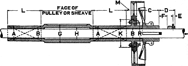
Fig. 2,858.—Quill drive. This is the proper transmission arrangement substitute for heavy service, requiring large pulleys, sheaves, gears, rotors, etc. It is a hollow shaft supported by independent bearings. The main driving shaft running through the quill is thus relieved of all transverse stresses. The power is transmitted to the quill by means of a friction or jaw clutch. When the clutch is thrown out the pulley or sheave stands idle and the driving shaft revolves freely within the quill. As there is no contact between moving parts there is no wear. Jaw clutches should be used for drives demanding positive angular displacement. They can only be thrown in and out of engagement when at rest. All very large clutch pulleys, sheaves, or gears designed to run loose on the line shaft are preferably mounted on quills. The letters A, B, C, etc., indicate the dimensions to be specified in ordering a quill.
Ques. What advantages have shell type transformers over those of the core type?
Ans. They have a larger proportion of core surface exposed for radiation of heat, and a shorter magnetic circuit which reduces the tendency for a leakage of the lines of force into the air.
Both types have advantages and disadvantages as compared with the other. In the shell type, there is less magnetic leakage, but also less surface exposed for radiation, and greater difficulty in providing efficient insulation between the two circuits; in the core type there is more surface exposed for radiation and less difficulty in insulating the windings, but there is also a great leakage of the lines of magnetic force into the outer air.
Ques. How are the windings usually arranged?
Ans. As a rule, there is only one primary winding but the secondary winding is generally divided into two equal sections, the four terminals of which are permanently wired to four connection blocks which may be connected so as to throw the secondary sections either in parallel or in series with each other at will.
Ques. What is necessary for satisfactory operation of transformers in parallel?
Ans. They must be designed for the same pressures and capacities, their percentages of regulation should be the same and they must have the same polarity at a given instant.
One may satisfy himself as to the first of these conditions by examining the name plates fastened to the transformers, whereon are stamped the values of the respective pressures and capacities of each.
Although equal values of regulation is given as one of the conditions to be satisfied, transformers may be operated in parallel when their percentages of regulation are not the same. Ideal operation, however, can be attained only under the former state of affairs. Suppose, for instance, a transformer having a regulation of two per cent. be operated in parallel with another of similar size and design but having a regulation of one per cent. The secondary pressures of these transformers at no load will of course be the same, but at full load if the secondary pressure of the one be 98 volts, that of the other will be 99 volts. There will, therefore, be a difference of pressure of one volt between them which will tend to force a current backward through the secondary winding of the transformer delivering 98 volts. This reversed current, although comparatively small in value, lowers the efficiency of the installation by causing a displacement of phase and a decrease in the combined power factor of the transformers.
Ques. Describe the polarity test.
Ans. The test for polarity consists in joining together by means of a fuse wire, a terminal of the secondary winding of each transformer, and then with the primary windings supplied with normal voltage, connecting temporarily the remaining terminals of the secondary windings. The melting of the fuse wire thus connected indicates that the secondary terminals joined together are of opposite polarities, and that the connections must therefore be reversed, whereas if the fuse wire do not melt, it shows that the proper terminals have been joined and that the connections may be made permanent.
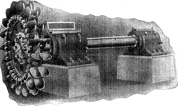
Fig. 2,859.—Single overhung tangential water wheel equipped with Doble ellipsoidal buckets. The central position of the front entering wedge or lip of the bucket is cut away in the form of a semi-circular notch, which allows a solid circular water jet to discharge upon the central dividing wedge of the bucket without being split in a horizontal plane.
The object of this test is, obviously, not to determine the exact polarity of each secondary terminal, but merely to indicate which of them are of the same polarity.
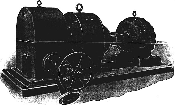
Fig. 2,860.—Motor generator exciter set driven by a Pelton-Doble tangential water wheel. The water wheel runner is mounted on the shaft overhung and the jet is regulated by either a hand actuated or governor controlled needle nozzle. The speed of the water wheel is equivalent to the synchronous speed of the induction motor, hence, the latter floats on the line, and under certain conditions may perform the functions of an alternator by feeding into the circuit, should the water wheel tend to operate above synchronous speed. Should any interruption to the operation of the wheel occur, causing a diminution of speed, the induction motor would drop back to full load speed and take up the exciter load, resulting in no appreciable drop of exciter voltage. The only variation of speed possible is dependent upon the "slip" of the motor. Where two or more exciter sets are employed in the station, an advantageous arrangement embraces the installation of a water wheel driven motor generator set and an exciter set, consisting of merely the direct current generator and water wheel. The induction motor being electrically tied into the circuit, the possibility of a runaway of the water wheel is eliminated, since its speed can only slightly exceed the synchronous speed of the system.
Motor Generators.—In motor generator sets, either the shunt or series wound type of motor may be employed at the power producing end of the set, but the field of the generator is either shunt or compound wound, depending upon whether or not it is desired to maintain or to raise the secondary voltage near full load. In either case a rheostat introduced in the shunt field winding of the generator will be found very essential. Both generator and motor are so mounted on the base that their respective commutators are at the outer ends of the set. By this means ample space surrounds all of the working parts, and repairs can readily be made.
Motor generators are frequently used as boosters to raise or boost the voltage near the extremities of long distance, direct current transmission lines. Of these, electric railway systems in which it is desired to extend certain of the longer lines, form a typical example.
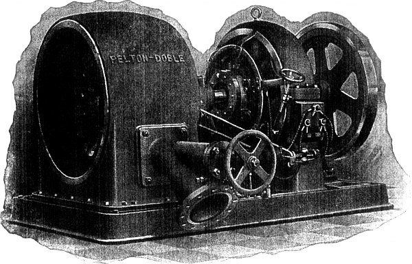
Fig. 2,861.—Automatically governed Pelton-Doble tangential water wheel driving exciter dynamo. The water wheel is mounted on one end of the shaft, while the opposite end is extended to carry a fly wheel of suitable design to compensate for the low fly wheel effect of the direct current armature. Two bearings support the shaft which carries the rotating elements of the unit. A needle nozzle actuated by a direct motion Pelton-Doble governor (designed for operation by either oil or water pressure) maintains constant speed.
Owing to the great cost of changing such a system over to one employing alternating current, or storage batteries, or of constructing an additional power station, these solutions of the problem are usually at variance with good judgment and the amount of money at hand. The choice then remains between the purchase of additional wire for feeders, the connection of a booster in the old feeders, or the installation of both larger feeders and a booster. Of these, it is generally found that either the second or the third mentioned alternative meets the conditions most satisfactorily.
A booster installed in a railway system for the purpose just mentioned, would have a series wound motor, and the conditions to which it must conform would be as follows: The motor having a series winding must provide for the full feeder current passing through both armature and field windings.
Owing to the varying loads on a railway system, due to the frequent starting and stopping of cars, the feeder current varies between zero and some such value as 150 amperes. This fluctuation of current through the field winding will, in ordinary cases, vary the magnetization of the pole pieces from zero almost to the point of saturation; that is, the maximum feeder current will so nearly fill the magnet cores with lines of force that it would be quite difficult to cause more lines of magnetic force to pass through them.
So long as the point of saturation is not reached, however, the proportion of current to field strength remains constant, and therefore the ratio of amperes to volts will not vary.
The severe fluctuations of the feeder current would, if the motor were shunt or compound wound, cause most serious sparking and various other troubles, but in a series motor where the back ampere turns on the armature that react on the field vary in precisely the same proportion as the ampere turns in the field, there exists at all times a tendency to balance the active forces and produce satisfactory operation. If, however, the field magnet cores be very large, they cannot so quickly respond, magnetically, to changes in the strength of the current, and there is then greater liability of the armature reaction momentarily weakening the field and thereby producing temporary sparking.
Ques. Are motor generators always composed of direct current sets?
Ans. No.
Ques. Describe conditions requiring a different combination.
Ans. For purposes where for instance direct currents of widely different voltages are to be obtained from an alternating current circuit, and it is desired to install but one set, a motor generator consisting of an alternating current motor such as an induction motor, and a dynamo must necessarily be employed.
In such sets, it is common to find both motor and dynamo armatures mounted on a common shaft, and the respective field frames resting on a single base, although for connection on a very high pressure alternating current circuit, separate armature shafts insulated from each other but directly connected together, and separate bases resting on a single foundation, are usually employed to afford the highest degree of insulation between the respective circuits of the two machines.
Ques. What is the objection to a set composed of alternating current motor and alternator?
Ans. The commercial field that would be naturally covered by such a set is better supplied by a transformer.
Ques. Why?
Ans. Because a transformer contains no moving parts, and is therefore simpler in construction, cheaper in price, and less liable to get out of order.
Dynamotors.—A dynamotor differs from a motor generator in that the motor armature and the generator armature are combined into one, thereby requiring but one field frame. Since the motor and generator armature windings are mounted on a single core, the armature reaction due to the one winding is neutralized by the reaction caused by the other winding. There is, consequently, little or no tendency for sparking to occur at the brushes, and they therefore need not be shifted on this account for different loads.
Ques. How is a dynamotor usually constructed?
Ans. It is usually built with two pole pieces which are shunt wound.
Ques. Why does the voltage developed fall off slightly under an increase of load?
Ans. Because a compound winding cannot be provided.
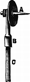
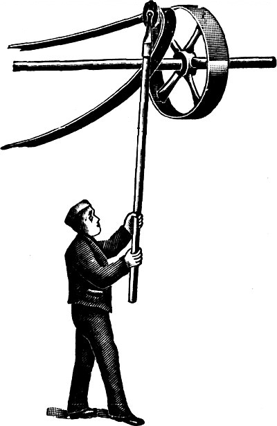
Figs. 2,862 and 2,863.—Method of putting on belts when the driver is in motion, and device used. The latter is called a belt slipper, and consists, as shown in fig. 2,862, of a cone and shield, which revolve upon the stem, B, thus yielding easily to the pull of the belt. A staff or handle C of any convenient length can be fastened to the socket. The mode of operation is illustrated in fig. 2,863, which is self explanatory.
Ques. Describe the armature construction and operation.
Ans. It consists of two separate windings; one of which is joined to a commutator mounted on one side of the armature for motor purposes, and the other to the commutator on the other side of the armature for generator purposes.
By means of two studs of brushes pressing on the motor commutator, current from the service wires is fed into the winding connected to this commutator, and since the shunt field winding is also excited by the current from the service wires, there is developed in the generator winding on the rotating armature a direct voltage which is proportional to the speed of rotation of the armature in revolutions per second, the number of conductors in series which constitute the generator winding, and the total strength of the field in which the armature revolves. This pressure causes current to pass through the generator winding and the distributing circuit when the distributing circuit to which this winding is connected by means of its respective commutator, brushes, etc., is closed.
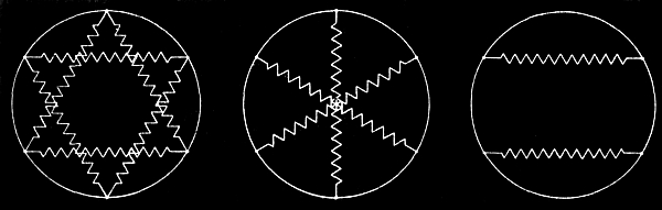
Figs. 2,864 to 2,866.—Converter connections; fig. 2,864 double delta connection; fig. 2,865 diametrical connection; fig. 2,866 two circuit single phase connection. For six phase synchronous converter, two different arrangements of the connections are generally used. One is called the double delta, and the other the diametrical connection. Let the armature winding of the converter be represented by a circle as in figs. 2,864 and 2,865, and let the six equidistant points on the circumference represent collector rings, then the secondary of the supply transformers can be connected to the collector rings in a double delta as in fig. 2,864, or across diametrical pairs of pointer as in fig. 2,865. In the first instance, the voltage ratio is the same as for the three phase synchronous converter and simply consists of two delta systems. The transformers can also be connected in double star, and in such a case the ratio between the three phase voltage between the terminals of each star, and the direct voltage will be the same as for double delta, while the voltage of each transformer coil, or voltage to neutral, is 1 ÷ √3 times as much. With the diametrical connection, the ratio is the same as for the two ring single phase converter, it being analogous to three such systems. Hence six phase double delta E1 = √3 E ÷ 2√2 = .612E. Six phase diametrical, E1 = E ÷ √2 = .707E. The ratio of the virtual_voltage E0 between any collector ring and the neutral point is always E0 = (E ÷ 2) √2 = .354E. For single phase synchronous converters, consisting of a closed circuit armature winding tapped at two equidistant points to the two collector rings the virtual voltage is 1 ÷ √2 × the direct current voltage. While such an arrangement of the single phase converter is the simplest, requiring only two collector rings, it is undesirable, especially for larger machines, on account of excessive heating of the armature conductors. In fig. 2,866, which represents the armature winding of a single phase converter, the supply circuits from two secondaries of the step down transformers are connected to four collector rings, so that the two circuits are in phase with each other, but each spreads over an arc of 120 electrical degrees instead of over 180 degrees as in the single phase circuit converter. To distinguish the two types, it is generally called a two circuit single phase synchronous converter. The virtual voltage E2 bears to the direct voltage the same relation as in the three phase converter, that is single phase two circuit, E1 = √3 ÷ 2√2 =.612E.
Ques. How is a dynamotor started?
Ans. It is connected at its motor end and started in the same manner as any shunt wound motor on a constant pressure circuit.
Ques. What precautions should be taken in starting a dynamotor?
Ans. The necessary precautions are, to have the poles strongly magnetized before passing current through the motor winding on the armature; to increase gradually the current through this winding, and not to close the generating circuit until normal conditions regarding speed, etc., are established in the motor circuit.
Ques. How is the current developed in the machine regulated?
Ans. It can be regulated by the introduction of resistance in one or the other of the armature circuits, or by a shifting of the brushes around the commutator.
Ques. Are dynamotors less efficient than motor generators of a similar type?
Ans. No, they are more efficient.
Ques. Why?
Ans. Because they have only one field circuit and at least one bearing less than a motor generator.
A motor generator has at least three bearings, and occasionally, four, where the set consists of two independent machines directly connected together.
Rotary Converters.—An important modification of the dynamotor is the rotary converter. This machine forms, as it were, a link between alternating and direct current systems, being in general a combination of an alternating current motor and a dynamo.
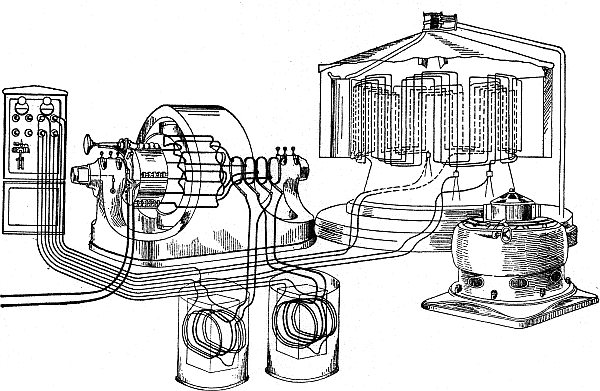
Fig. 2,867.—Skeleton diagram showing wiring of alternator, exciter, transformer and converter. The cut also shows switchboard and connections.
It has practically become a fixture in all large electric railway systems and in other installations where heavy direct currents of constant pressure are required at a considerable distance from the generating plant. In such cases a rotary converter is installed in the sub-station, and being simpler in construction, higher in efficiency, more economical of floor space, and lower in price than a motor generator set consisting of an alternating current motor and a dynamo which might be used in its place, it has almost entirely superseded the latter machine for the class of work mentioned.
Ques. What is the objection to the single phase rotary converter?
Ans. It is not self-starting.
Ques. What feature of operation is inherent in a rotary converter?
Ans. A rotary converter is a "reversible machine."
That is to say, if it be supplied with direct current of the proper voltage at its commutator end, it will run as a direct current motor and deliver alternating current to the collector rings. While this feature is sometimes taken advantage of in starting the converter from rest, the machine is not often used permanently in this way, its commercial application being usually the conversion of alternating currents into direct currents.
Ques. How does a rotary converter operate when driven by direct current?
Ans. The same as a direct current motor, its speed of rotation depending upon the relation existing between the strength of the field and the direct current voltage applied.
If the field be weak with respect to the armature magnetism resulting from the applied voltage, the armature will rotate at a high speed, increasing until the conductors on the armature cut the lines of force in the field so as to develop a voltage which will be equal to that applied.
Again, if the field be strong with respect to the armature magnetism, resulting from the applied voltage, the armature will rotate at a low speed. If, therefore, it be desired to operate the converter in this manner and maintain an alternating current of constant frequency, the speed of rotation must be kept constant by supplying a constant voltage not only to the brushes pressing on the commutator, but also to the terminals of the field winding.
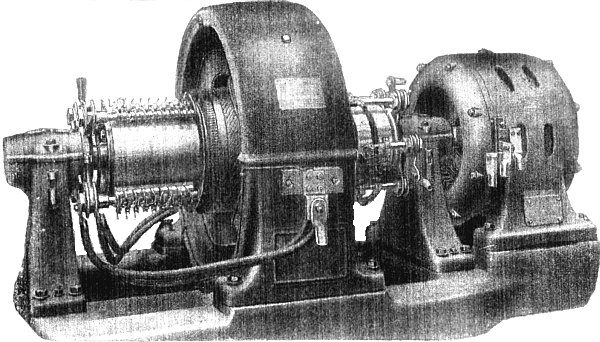
Fig. 2,868.—General Electric synchronous converter with series booster. This type of converter generally consists of an alternator with revolving field mounted on the same shaft as the converter armature. The armature of the alternator, or booster, as it is usually called, is stationary and connected electrically in series between the supply circuit and the collector rings of the synchronous converter. The booster field has the same number of pole as the converter and is generally shunt wound. A change in the booster voltage will correspondingly change the alternating voltage impressed on the converter and this regulation can, of course, be made so as to either increase or decrease the impressed voltage by means of strengthening or weakening the booster field. The voltage variation can be made either non-automatic or automatic, and in the latter case, it becomes necessary to provide a motor operated rheostat controlled by suitable relays, or the booster can be provided with a series field. By means of a booster, it is possible to vary the direct voltage of the converter with a constant alternating supply voltage, and this voltage regulation is obtained without disturbance of the power factor or wave shape of the system. Synchronous converters are frequently installed in connection with Edison systems, where three wire direct current is required. The three wire feature is obtained either by providing extra collector rings and compensator, as with ordinary direct current generators, or also by connecting the neutral wire directly to the neutral point of the secondary winding of step down transformers, if such be furnished.
Ques. How does it operate with alternating current drive?
Ans. The same as a synchronous motor.
Ques. What is the most troublesome part and why?
Ans. The commutator, because of the many pieces of which it is composed and the necessary lines along which it is constructed, its peripheral speed must be kept within reasonable limits.
Ques. What should be the limit of the commutator speed?
Ans. The commutator speed, or tangential speed at the brushes should not exceed 3,000 feet per minute.
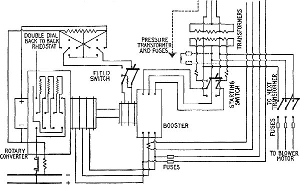
Fig. 2,869.—Wiring diagram for General Electric synchronous converter with series booster as illustrated in fig. 2,868.
Ques. Name another limitation necessary for satisfactory operation.
Ans. The pressure between adjacent commutator bars should not exceed eight or ten volts.
If the commutator bars be made narrow in order to obtain the necessary number for the desired voltage with the minimum circumference and therefore low commutator speed, the brushes employed to collect the current are liable to require excessive width in order to provide the proper cross section and yet not cover more than two bars at once.
Ques. How can the commutator speed be kept within reasonable limits, other than by reducing the width of the commutator bars?
Ans. By using alternating current of comparatively low frequency.
For a rotary converter delivering 500 volt direct current, the proper frequency for the alternating current circuit has been found to be 25 cycles per second.
Ques. When a rotary converter is operated in this usual manner on an alternating current circuit, how can the direct current be varied?
Ans. It may be varied (from zero to a maximum) by changing the value of the alternating pressure supplied to the machine, or it may be altered within a limited range by moving the brushes around the commutator, or in a compound wound converter by changing the amount of compounding.
Under ordinary conditions, varying the voltage developed by changing the voltage at the motor end is not practical, hence the voltage developed can be varied only over a limited range. In addition to this, the voltage developed at the direct current end bears always a certain constant proportion to the alternating current voltage applied at the motor end; this is due to the same winding being used both for motor and generator purposes. In all cases the proportion is such that the alternating current voltage is the lower, being in the single phase and in the two phase converters about .707 of the direct current voltage, and in the three phase converter about .612 of the direct current voltage. It is thus seen that whatever value of direct current voltage be desired, the value of the applied alternating current voltage must be lower, requiring in consequence the installation of step down transformers at the sub-station for reducing the line wire voltage to conform to the direct current pressure required.
Ques. What is the efficiency of a rotary converter?
Ans. It may be said to have approximately the same efficiency as that in the average of the same output, although in reality the converter is a trifle more efficient on account of affording a somewhat shorter average path for the current in the armature, reducing in consequence the resistance loss and the armature reaction.
Ques. May a converter be overloaded more than a dynamo of the same output, and why?
Ans. Yes, because there is usually less resistance loss in the armature of the converter than in the armature of the dynamo.
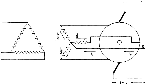
Fig. 2,870.—Wiring diagram for three wire synchronous converter with delta-Y connected step down transformer with the neutral brought out. It is evident that in this case each transformer secondary receives ⅓ of the neutral current, and if this current be not so small, as compared with the exciting current of the transformer, it will cause an increase in the magnetic density.
Thus, a two phase converter may be overloaded approximately 60 per cent., and a three phase converter may be overloaded about 30 per cent. above their respective outputs if operated as dynamos.
Ques. Describe how a converter is started.
Ans. There are several methods any one of which may be employed, the choice in any given case depending upon which of them may best be followed under the existing conditions.
If it be found advisable to start the converter with direct current, the same connections would be made between the source of the direct current and the armature terminals on the commutator side of the converter as would be the case were a direct current shunt motor of considerable size to be started; this naturally means that a starting rheostat and a circuit breaker will be introduced in the armature circuit.
The shunt field winding alone is used, and this part of the wiring may be made permanent if, as is usually the case, the same source of direct current is used normally for separate field excitation.
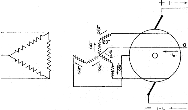
Fig. 2,871.—Wiring diagram of three wire synchronous converter with distributed Y secondary. This system eliminates the flux distortion due to the unbalanced direct current in the neutral. Two separate interconnected windings are used for each leg of the Y. The unbalanced neutral current flowing in this system may be compared in action to the effect of a magnetizing current in a transformer. The effect of the main transformer currents in the primary and secondary is balanced with regard to the flux in the transformer core, which depends upon the magnetic current. When a direct current is passed through the transformer, unless the fluxes produced by the same neutralize one another, its effect on the transformer iron varies as the magnetizing current. For example, assume a transformer having a normal ampere capacity of 100 and, approximately, 6 amperes magnetizing current, and assume that three such transformers are used with Y connected secondaries for operating a synchronous converter connected to a three wire Edison system. Allowing 25 per cent. unbalancing, the current will divide equally among the three legs giving 8.33 amperes per leg, which is more than the normal magnetizing current. The loss due to this current is, however, inappreciable, but the increased core losses may be considerable. If a distributed winding be used, the direct current flows in the opposite direction, around the halves of each core thus entirely neutralizing the flux distortion. Whether the straight Y connection is to be used is merely a question of balancing the increased core loss of the straight Y connection against the increased copper loss and the greater cost of the interconnected Y system. The straight Y connection is much simpler, and it would be quite permissible to use it for transformers of small capacities where the direct current circulating in the neutral is less than 30 per cent. of the rated transformer current.
The direct current may be derived from a storage battery, from a separate converter, or from a motor generator set installed in the sub-station for the purpose.
An adjustable rheostat will, of course, be connected in the field circuit for regulation. Before starting the converter, however, it is necessary to do certain wiring between the terminals on the collector side of the machine and the alternating current supply wires, in order that the change over from direct current motive power to alternating current motive power may be made when the proper phase relations are established between the alternating current in the supply wires and the alternating current in the armature winding of the converter.
In order that proper phase relations exist, the armature of the converter must rotate at such a speed that each coil thereon passes its proper reversal point at the same time as the alternating current reverses in the supply wires. This speed may be calculated by doubling the frequency of the supply current and then dividing by the number of pole pieces on the converter, but a far more accurate method of judging when the converter is in step or in synchronism with the supply current consists in employing incandescent lamps as shown in fig. 2,872.
Ques. How is a polyphase converter started with alternating current?
Ans. This may be done by applying the alternating pressure directly to the collector rings while the armature is at rest. There need be no field excitation; in fact the field windings on the separate pole pieces should be disconnected from each other before the alternating voltage is applied to the armature, else a high voltage will be induced in the field windings which may prove injurious to their insulation. The passage of the alternating current through the armature winding produces a magnetic field that rotates about the armature core, and induces in the pole pieces eddy currents, which, reacting on the armature, exert a sufficient torque to start the converter from rest and cause it to speed up to synchronism.
Ques. How much alternating current is required to start a polyphase converter?
Ans. About 100 per cent. more than that required for full load.
Ques. How may this starting current be reduced?
Ans. Transformers may be switched into circuit temporarily to reduce the line wire voltage until the speed become normal.
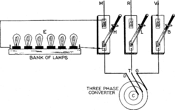
Fig. 2,872.—Wiring diagram showing arrangement of incandescent lamps for determining the proper phase relations in starting a rotary converter. The alternating current side of a three phase converter is shown at C. The three brushes, D, T and G pressing on its collector rings are joined in order to the three single pole switches H, L and B which can be made to connect with the respective wires M, R, and V, of the alternating current supply circuit. Across one of the outside switches, H, for example, a number of incandescent lamps are joined in series as indicated at E, while the three pole switch (not shown) in the main circuit, between the alternator and the single pole switches is open. If then the main switch just mentioned and the middle switch L be both closed, and the armature of the alternator be brought up to normal speed by running it as a direct current motor, the lamps at E will light up and darken in rapid succession; the lighting and darkening of the lamps will continue until, by a proper adjustment of the speed, the correct phase relations be established between the alternating current in the supply circuit and the alternating current developed in the armature of the converter. As this condition is approached, the intervals between the successive lighting up and darkening of the lamps will increase until they remain perfectly dark. There is then no difference of pressure between the supply circuit M R V and the rotary converter armature circuit, so the source of the direct current may at that instant be disconnected from the machine, and the switches H and B, closed. If the change over has been accomplished before the phase relations of the two circuits differed, the converter will at once conform itself to the supply circuit and run thereon as a synchronous motor without further trouble. The opening of the direct current circuit and the closing of the alternating current supply circuit may be done by hand, but preferably by employing a device that will automatically trip the circuit breaker in the direct current circuit at the instant the switches in the alternating current circuit are closed.
In conjunction with this method, the method of synchronizing shown in fig. 2,872 may be used, thus, in starting, there is an alternating current between the brushes which pulsates very rapidly, but when synchronism is approached, the pulsations become less rapid until finally with the converter in step with the alternator the pulsations entirely disappear.
The light given by the lamps thus connected indicates accurately the condition of affairs at any one time, varying from a rapidly fluctuating light at the beginning to one of constant brilliancy at synchronism.
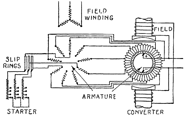
Fig. 2,873.—Diagram of motor converter. This machine which is only to be used for converting from alternating to direct current, consists of an ordinary induction motor with phase wound armature, and a dynamo. The revolving parts of both machines are mounted on the same shaft and from the figure it is seen that the armature of the motor and the armature of the dynamo are also electrically connected. The motor converter is a synchronous machine, but the dynamo receives the current from the armature of the motor at a frequency much reduced from that impressed upon the field winding of the motor. Assuming that the motor and the converter have the same number of pole, the motor will rotate at a speed corresponding to one-half the frequency of the supply circuit. The motor will operate half as a motor and half as a transformer, and the converter, half as a dynamo and half as a synchronous converter, in that one-half of the electrical energy supplied to the motor will be converted into mechanical power for driving the converter, while the other one-half is transferred to the secondary motor windings and thereby to the converter armature in the form of electrical power. The capacity of the motor is theoretically only half what it would be if it were to convert the whole of the electrical energy into mechanical power because the rating depends upon the speed of the rotating field and not on that of the rotor. If the two machines have a different number of pole, or are connected to run at different speeds, the division of power is at a different but constant ratio. The machine starts up as an ordinary polyphase induction motor and the field of the converter is built up as though it were an ordinary dynamo. Motor converters are occasionally used on high frequency systems, as their commutating component is of half frequency, and thus permits better commutator design than a high frequency converter. The advantage of this type of machine is that for phase control it requires no extra reactive coils, the motor itself having sufficient reactance. It is, however, larger than standard converters, but smaller than motor generators, as half the power is converted in each machine. Its efficiency is less than for synchronous converters, and the danger of reaching double speed in case of a short circuit on the direct current side is very great. It has been used abroad to some extent for 60 cycle work, in preference to synchronous converters, but with the present reliable design of 60 cycle converters, and the general use of 25 cycles, where severe service conditions are met, as in railroading, motor converters should not be recommended.
Ques. If the armature of the starting motor have a starting resistance, how must this be connected?
Ans. It should be connected in series with the armature inductors before the alternating voltage is applied.
As the motor increases in speed, the starting resistance is gradually short circuited until it is entirely cut out of circuit.
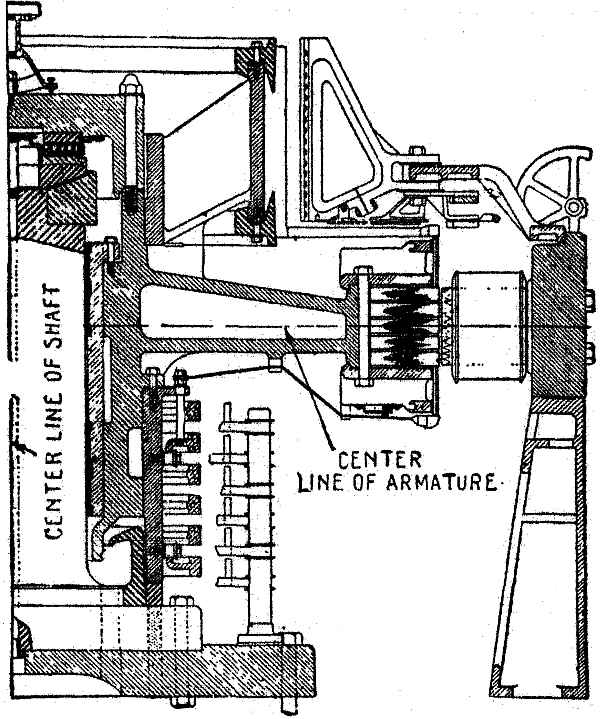
Fig. 2,874.—Sectional view of General Electric vertical synchronous converter. In this construction, the field frame carrying the poles is mounted on cast iron pedestals and is split vertically. This allows the two halves of the frame to be separated for inspection or repairs of the armature. The armature, including commutator and collector rings, is mounted on a vertical stationary shaft, which is rigidly supported from the foundation. The thrust of the armature is carried on a roller bearing attached to the top of the shaft and upper side of the armature spider. The under side of the lower plate of the roller bearing is made spherical and fits into a corresponding spherical cup on the end of the shaft, making the bearing self aligning. The armature spider has a babbitted sleeve along the fit of the vertical shaft, which acts as a guide bearing and has to take only the thrust due to the unbalancing effect of the rotating parts. A circulating pump furnishes oil to the roller bearing, the oil draining off through the guide bearing. A marked advantage of this type of construction is the accessibility of the commutator for adjustment of the brushes, etc., as there is no pit or pedestal bearing to interfere.
NOTE.—Some converters are provided with a small induction motor for starting mounted on an iron bracket cast in the converter frame, and whose shaft is keyed to that of the converter. Allowing for a certain amount of slip in the induction motor, the field of this machine must possess a less number of magnet poles than the converter in order to enable the latter machine to be brought to full synchronism. To start the induction motor, it is simply necessary to apply to its field terminals the proper alternating voltage. The bracket, and therefore the motor, is usually mounted outside the armature bearing on the collector side of the converter.
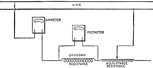
Fig. 2,875.—Resistance measurement by "drop" method. The circuit whose resistance is to be measured, is connected in series with an ammeter and an adjustable resistance to vary the flow of current. A voltmeter is connected directly across the terminals of the resistance to be measured, as shown in the figure. According to Ohm's law I = E ÷ R, from which, R = E ÷ I. If then the current flowing in the circuit through the unknown resistance be measured, and also the drop or difference of pressure, the resistance can be calculated by above formula. In order to secure accurate determination of the resistance such value of current must be used as will give large deflections of the needle on the instruments employed. A number of independent readings should be taken with some variation of the current and necessarily a corresponding variation in voltage. The resistance should then be figured from each set of readings and the average of all readings taken for the correct resistance. Great care must be taken, however, in the readings, and the instruments must be fairly accurate. For example, suppose that the combined instrument error and the error of the reading in the voltmeter should be 1 per cent., the reading being high, while the corresponding error of the ammeter is 1 per cent. low. This would cause an error of approximately 2 per cent. in the reading of the resistance. In making careful measurements of the resistance, it is also necessary to determine the temperature of the resistance being measured, as the resistance of copper increases approximately .4 of 1 per cent. for each degree rise in temperature. Use is made of this fact for determining the increase in temperature of a piece of apparatus when operating under load. The resistance of the apparatus at some known temperature is measured, this being called the cold resistance of the apparatus. At the end of the temperature test the hot resistance is taken. Assume the resistance has increased by 15 per cent. This would indicate a rise in temperature of 37½ degrees above the original or cold temperature of the apparatus. Suppose then that in measuring the cold resistance, results are obtained which are 2 per cent. low, and that in measuring the hot resistance, there be 2 per cent. error in the opposite direction. This would mean that a total error of 4 per cent. had been made in the difference between the hot and cold resistances, or an error of 10 degrees. The correct rise in temperature is, therefore, about 27½ instead of 37½ degrees. In other words, an error of 2 per cent. in measuring each resistance has caused an error of approximately 36½ per cent. in the measurement of the rise in temperature. The constant .4 which has been used above is only approximate and should not be used for exact work. For detail instructions of making calculations of resistance and temperature, see "Standardization Rules of the A.I.E.E."
Ques. Describe the usual wiring for the installation of a rotary converter in a sub-station.
Ans. Commencing at the entrance of the high pressure cables, first there is the wiring for the lightning arresters, then for the connection in circuit of the high tension switching devices, from which the conductors are led to bus bars, and thence to the step down transformers.
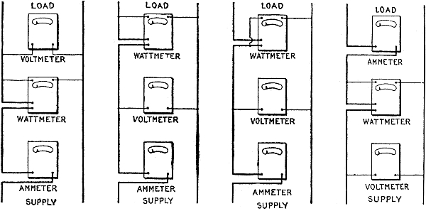
Figs. 2,876 to 2,879.—How to connect instruments for power measurement. There are several ways of connecting an ammeter, voltmeter and wattmeter in the circuit for the measurement of power. A few of the methods are discussed below. With some of the connections it is necessary to correct the readings of the wattmeter for the losses in the coil, or coils, of the wattmeter, or for losses in ammeter or voltmeter. This is necessary since the instruments may be so connected that the wattmeter not only measures the load but includes in its indications some of the instrument losses. If the load measured be small, or considerable accuracy is required, these instrument losses may be calculated as follows: Loss in pressure coils is E2 ÷ R, in which E is the voltage at the terminals of the pressure coil and R is the resistance. Loss in current coil is I2 R in which I is the current flowing and R the resistance of the current coil. In general let Ev = voltage across terminals of the voltmeter; Ew = voltage across the terminals of the pressure coil of the wattmeter; Iw = current through current coil of wattmeter; Ia = current through current coil of ammeter; Rv = resistance of pressure coil of voltmeter; Rw = resistance of pressure coil of wattmeter; R1w = resistance of current coil of wattmeter; Ra = resistance of current coil of ammeter. Then the losses in the various coils will be as follows: E2v ÷ Rv = loss in pressure coil of voltmeter. E2w ÷ Rw = loss in pressure coil of wattmeter. I2w ÷ Rv = loss in current coil of wattmeter. I2aRa = loss in current coil of ammeter. If connection be made as in fig. 2,876, the correct power of the circuit will be the wattmeter reading W-(E2v ÷ Rv + E2w ÷ Rw) in which Ev = Ew. In fig. 2,877, the power is W-E2w ÷ Rw. In fig. 2,878, the power is W-I2wR1w, or the correct power is the wattmeter reading minus the loss in the current coil of the wattmeter. In fig. 2,879, the power is W-(E2w ÷ Rw + I2aRa)· The usual method of connection is either as in fig. 2,876 or fig. 2,877. In either case the current reading is that of the load plus the currents in the pressure coils of the voltmeter and wattmeter. Unless the current being measured, however, is very small, or extreme accuracy is desired, it is unnecessary to correct ammeter readings. In fig. 2,877 a small error is introduced due to the fact that the actual voltage applied to the load is that given by the voltmeter minus the small drop in voltage through the current coil of the wattmeter. If an accurate measure of the current in connection with the power consumed by the load be required, the connections shown in fig. 2,879 are used, and if extreme accuracy is required, the wattmeter reading is reduced by the losses in the ammeter and in the pressure coil of the wattmeter. The loss in the pressure coil of a wattmeter or voltmeter may be as high as 12 or 15 watts at 220 volts. The loss in the current coil of a wattmeter with 10 amperes flowing may be 6 or 8 watts. It can be easily seen that if the core or copper losses of small transformers are being measured, it is quite necessary to correct the wattmeter readings, for the instrument losses. In measuring the losses of a 25 or 50 H.P. induction motor, the instrument losses may be neglected. A careful study of the above will show when it becomes necessary to correct for instrument losses and the method of making these corrections. Connections are seldom used which make it necessary to correct for the losses in the current coils of either ammeter or wattmeter, as the losses vary with the change in the current. On the other hand, the voltages generally used are fairly constant at 110 or 220, and when the losses of the pressure coils at these voltages have once been calculated, the necessary instrument correction can be readily made.
On a three phase system the transformers should be joined in delta connection, as a considerable advantage is thereby gained over the star connection, in that should one of the transformers become defective, the remaining two will carry the load without change except more or less additional heating. Between the transformers and rotary converter the circuits should be as short and simple as possible, switches, fuses, and other instruments being entirely excluded. The direct current from the converter is led to the direct current switchboard, and from there distributed to the feeder circuits.
WATTMETER ERROR FOR A LOAD OF 1,000 VOLT-AMPERES
(For a lag of 1 degree in the pressure coil)
Power factor True watts Error Error of indication in per cent of true value
1. 1,000 .3 0.03
.9 900 7.6 0.85
.8 800 10.5 1.31
.7 700 12.5 1.78
.6 600 13.9 2.32
.5 500 15.1 3.02
.4 400 15.9 3.98
.3 300 16.6 5.54
.2 200 17.1 8.55
.1 100 17.3 17.30
NOTE.—In the iron vane type instrument when used as a wattmeter, the current of the series coil always remains in perfect phase with the current of the circuit, provided series transformers are not introduced. The error, then, is entirely due to the lag of the current in the pressure coil, and this error in high power factor is exceedingly small, increasing as the power factor decreases. In the above table it should be noted that the value of the error as distinguished from the per cent. of error, instead of indefinitely increasing as the power factor diminishes, rapidly attains a maximum value which is less than 2 per cent. of the power delivered under the same current and without inductance. It should also be noted that the above tabulation is on the assumption of a lag of 1 degree in the pressure coil. The actual lag in Wagner instruments for instance, is approximately .085 of a degree, and the error due to the lag of the pressure coil in Wagner instruments is, therefore, proportionally reduced from the figures shown in the above tabulation.
Ques. In large sub-stations containing several rotary converters how are they operated?
Ans. Frequently they are installed to receive their respective currents from the same set of bus bars; that is, they may be operated as alternating current motors in parallel. They are also frequently operated independently from single bus bars, but very seldom in series with each other.
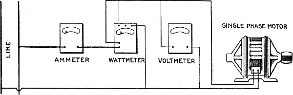
Fig. 2,880.—Single phase motor test. In this method of measuring the input of a single phase motor of any type, the ammeter, voltmeter and wattmeter are connected as shown in the illustration. The ammeter measures the current flowing through the motor, the voltmeter, the pressure across the terminals of the motor, and the wattmeter the total power which flows through the motor circuit. With the connections as shown, the wattmeter would also measure the slight losses in the voltmeter and the pressure coil of the wattmeter, but for motors of ¼ H.P. and larger, this loss is so small that it may be neglected. The power factor may be calculated by dividing the true watts as indicated by the wattmeter, by the product of the volts and amperes.
Ques. How may the direct current circuit be connected?
Ans. In parallel.
NOTE.—In motor testing, by the methods illustrated in the accompanying cuts, it is assumed that the motor is loaded in the ordinary way by belting or direct connecting the motor to some form of load, and that the object is to determine whether the motor is over or under loaded, and approximately what per cent. of full load it is carrying. All commercial motors have name plates, giving the rating of the motor and the full load current in amperes. Hence the per cent. of load carried can be determined approximately by measuring the current input and the voltage. If an efficiency test of the apparatus be required, it becomes necessary to use some form of absorption by dynamometer, such as a Prony or other form of brake. The output of the motor can then be determined from the brake readings. The scope of the present treatment is, however, too limited to go into the subject of different methods of measuring the output of the apparatus, and is confined rather to methods of measuring current input, voltage, and watts. The accuracy of all tests is obviously dependent upon the accuracy of the instruments employed. Before accepting the result obtained by any test, especially under light or no load, correction should be made for wattmeter error. See table of wattmeter error on page 2,075.
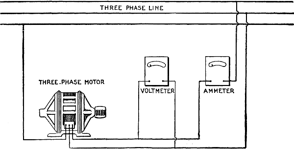
Fig. 2,881.—Three phase motor test; voltmeter and ammeter method. If it be desired to determine the approximate load on a three phase motor, this may be done by means of the connections as shown in the figure, and the current through one of the three lines and the voltage across the phase measured. If the voltage be approximately the rated voltage of the motor and the amperes the rated current of the motor (as noted on the name plate) it may be assumed that the motor is carrying approximately full load. If, on the other hand, the amperes show much in excess of full load rating, the motor is carrying an overload. The heat generated in the copper varies as the square of the current. That generated in the iron varies anywhere from the 1.6 power, to the square. This method is very convenient if a wattmeter be not available, although, it is, of course, of no value for the determination of the efficiency or power factor of the apparatus. This method gives fairly accurate results, providing the load on the three phases of the motor be fairly well balanced. If there be much difference, however, in the voltage of the three phases, the ammeter should be switched from one circuit to another, and the current measured in each phase. If the motor be very lightly loaded and the voltage of the different phases vary by 2 or 3 per cent., the current in the three legs of the circuit will vary 20 to 30 per cent.
Ques. What provision should be made against interruption of service in sub-stations?
Ans. There should be one reserve rotary converter to every three or four converters actually required.
Ques. Why does a rotary converter operate with greater efficiency, and require less attention than does a dynamo of the same output?
Ans. There is less friction, and less armature resistance, the latter because the alternating current at certain portions of each revolution passes directly to the commutator bars without traversing the entire armature winding as it does in a dynamo; there is no distortion of the field and consequently no sparking, or shifting of the brushes, since the armature reaction resulting from the current fed into the machine and that due to the current generated in the armature completely neutralizes each other.
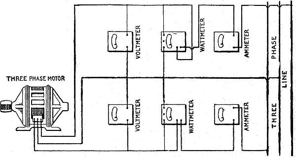
Fig. 2,882.—Three phase motor test by the two wattmeter method. If an accurate test of a three phase motor be required, it is necessary to use the method here indicated. Assume the motor to be loaded with a brake so that its output can be determined. This method gives correct results even with considerable unbalancing in the voltages of the three phases. With the connections as shown, the sum of the two wattmeter readings gives the total power in the circuit. Neither meter by itself measures the power in any one of the three phases. In fact, with light load one of the meters will probably give a negative reading, and it will then be necessary to either reverse its current or pressure leads in order that the deflection may be noted. In such cases the algebraic sums of the two readings must be taken. In, other words, if one read plus 500 watts and the other, minus 300 watts, the total power in the circuit will be 500 minus 300, or 200 watts. As the load comes on, the readings of the instrument which gave the negative deflection will decrease until the reading drops to zero, and it will then be necessary to again reverse the pressure leads on this wattmeter. Thereafter the readings of both instruments will be positive, and the numerical sum of the two should be taken as the measurement of the load. If one set of the instruments be removed from the circuit, the reading of the remaining wattmeter will have no meaning. As stated above, it will not indicate the power under these conditions in any one phase of the circuit. The power factor is obtained by dividing the actual watts input by the product of the average of the voltmeter readings × the average of the ampere readings × 1.73.
What electrical difficulty is experienced with a rotary converter?
Ans. Regulation of the direct current voltage.
Ques. How is this done?
Ans. It can be maintained constant only by preserving uniform conditions of inductance in the alternating current circuit, and uniform conditions in the alternator.
While changes in either of these may be compensated to a certain extent by adjustment of the field strength of the converter, they cannot be entirely neutralized in this manner; it is therefore necessary that both the line circuit and the alternator be given attention if the best results are to be obtained from the converter.
Ques. What mechanical difficulty is experienced with rotary converters?
Ans. Hunting.
Ques. What is the cause of this?
Ans. It is due to a variation in frequency.
The inertia of the converter armature tends to maintain a constant speed; variations in the frequency of the supply circuit will cause a displacement of phase between the current in the armature and that in the line wires, which displacement, however, the synchronizing current strives to decrease. The synchronizing current, although beneficial in remedying the trouble after it occurs, exerts but little effort in preventing it, and many attempts have been made to devise a plan to eliminate this trouble.
NOTE.—Three phase motor test; polyphase wattmeter method. This is identical with the test of fig. 2,882, except that the wattmeter itself combines the movement of the two wattmeters. Otherwise the method of making the measurements is identical. If the power factor be known to be less than 50 per cent., connect one movement so as to give a positive deflection; then disconnect movement one and connect movement two so as to give a positive deflection. Then reverse either the pressure or current leads of the movement, giving the smaller deflection, leaving the remaining movement with the original connections. The readings now obtained will be the correct total watts delivered to the motor. If the power factor be known to be over 50 per cent., the same methods should be employed, except that both movements should be independently connected to give positive readings. An unloaded induction motor has a power factor of less than 50 per cent., and may, therefore, be used as above for determining the correct connections. For a better understanding of the reasons for the above method of procedure, the explanation of the two wattmeter method, fig. 2,882, should be read. The power factor may be calculated as explained under fig. 2,882. Connect as shown in fig 2,882. The following check on connection may be made. Let the polyphase induction motor run idle, that is, with no load. The motor will then operate with a power factor less than 50 per cent. The polyphase meter should give a positive indication, but if each movement be tried separately one will be found to give a negative reading, the other movement will give a positive reading. This can be done by disconnecting one of the pressure leads from the binding post of one movement. When the power factor is above 50 per cent. then both movements will give positive deflection.
Ques. What are the methods employed to prevent hunting?
Ans. 1, the employment of a strongly magnetized field relative to that developed by the armature; 2, a heavy flywheel effect in the converter; 3, the increasing of the inductance of the armature by sinking the windings thereon in deep slots in the core, the slots being provided with extended heads; and 4, the employment of damping devices or amortisseur winding on the pole pieces of the converter.
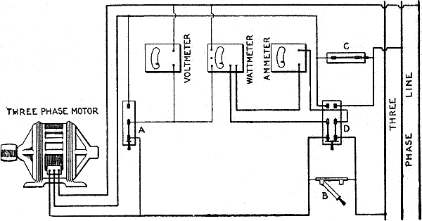
Fig. 2,883.—Three phase motor test; one wattmeter method. This method is equivalent to the two wattmeter method with the following difference. A single voltmeter (as shown above) with a switch, A, can be used to connect the voltmeter across either one of the two phases. Three switches, B, C and D, are employed for changing the connection of the ammeter and wattmeter in either one of the two lines. With the switches B and D in the position shown, the ammeter and wattmeter series coils are connected in the left hand line. The switch C must be closed under these conditions in order to have the middle line closed. Another reading should then be taken before any change of load has occurred, with switch A thrown to the right, switch B closed, switch D thrown to the right and switch C opened. The ammeter and the current coil of the wattmeter will then be connected to the middle line of the motor. In order to prevent any interruption of the circuit, the switches B, D and C should be operated in the order given above. With very light load on the motor the wattmeter will probably give a negative deflection in one phase or the other, and it will be necessary to reverse its connections before taking the readings. For this purpose a double pole, double throw switch is sometimes inserted in the circuit of the pressure coil of the wattmeter so that the indications can be reversed without disturbing any of the connections. It is suggested, before undertaking this test, that the instructions for test by the two wattmeter and by the polyphase wattmeter methods be read.
Ques. What method is the best?
Ans. The damping method.
The devices employed for the purpose are usually copper shields placed between or around the pole pieces, although in some converters the copper is embedded in the poles, and in others it is made simply to surround a portion of the pole tips.
In any case its action is as follows: The armature rotating at a variable speed has a field developed therein which is assumed to be also rotating at a variable speed; the magnetism of this rotary field induces currents in the copper which, however, react on the armature and oppose any tendency toward a further shifting of the magnetism in the armature and therefore prevent the development of additional currents in the copper. Since copper is of low resistance, the induced currents are sufficient in strength to thus dampen any tendency toward phase displacement, and so exert a steadying influence upon the installation as a whole.
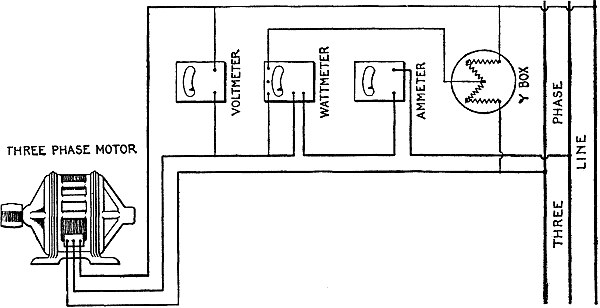
Fig. 2,884.—Three phase motor, one wattmeter and Y box method. This method is of service, only, provided the voltages of the three phases are the same. A slight variation of the voltage of the different phases may cause a very large error in the readings of the wattmeter, and inasmuch as the voltage of all commercial three phase circuits is more or less unbalanced, this method is not to be recommended for motor testing. With balanced voltage in all three phases, the power is that indicated by the wattmeter, multiplied by three. Power factor may be calculated as before.
Electrical Measuring Instruments.—In the manufacture of most measuring instruments, the graduations of the scale are made at the factory, by comparing the deflections of the pointer with voltages as measured on standard apparatus. The voltmeters in most common use have capacities of 5, 15, 75, 150, 300, 500 and 750 volts each, although in the measurement of very low resistances such as those of armatures, heavy cables, or bus bars, voltmeters having capacities as low as .02 volt are employed.
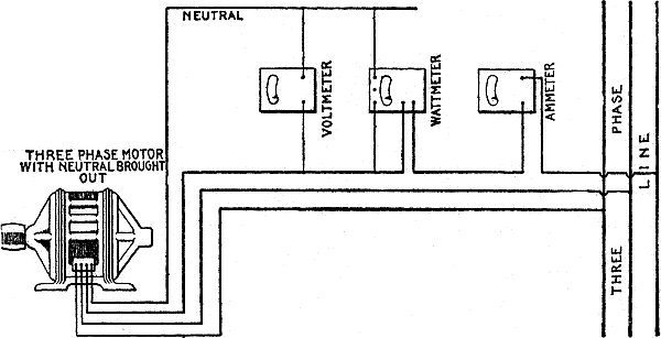
Fig. 2,885.—Test of three phase motor with neutral brought out; single wattmeter method. Some star connected motors have the connection brought out from the neutral of the winding. In this case the circuit may be connected, as here shown. The voltmeter now measures voltage between the neutral and one of the lines, and the wattmeter the power in one of the three phases of the motor. Therefore, the total power taken by the motor will be three times the wattmeter readings. By this method, just as accurate results can be obtained as with the two wattmeter method. The power factor will be the indicated watts divided by the product of the indicated amperes and volts.
The difference between the design of direct current voltmeters of different capacities lies simply in the high resistance joined in series with the fine wire coil. This resistance is usually about 100 ohms per volt capacity of the meter, and is composed of fine silk covered copper wire wound non-inductively on a wooden spool.
In the operation of an instrument, if the pointer when deflected do not readily come to a position of rest owing to friction in the moving parts, it may be aided in this respect by gently tapping the case of the instrument with the hand; this will often enable the obstruction, if not of a serious nature, to be overcome and an accurate reading to be obtained.
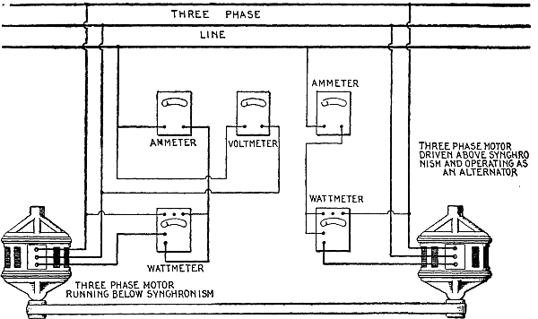
Fig. 2,886.—Temperature test of a large three phase induction motor. Temperature tests are usually made on small induction motors by belting the motor to a generator and loading the generator with a lamp bank or resistance until the motor input is equal to the full load. If, however, the motor be of considerable size, such that the cost of power becomes a considerable item in the cost of testing, the method here shown may be employed. For this purpose, however, two motors, preferably of the same size and type, are required. One is driven as a motor and runs slightly below synchronism, due to its slip when operating with load. This motor is belted to a second machine. If the pulley of the second machine be smaller than the pulley of the first machine, the second machine will then operate as an induction generator, and will return to the line as much power as the first motor draws from the line, less the losses of the second machine. By properly selecting the ratio of pulleys, the first machine can be caused to draw full load current and full load energy from the line. In this way, the total energy consumed is equivalent to the total of the losses of both machines, which is approximately twice the losses of a single machine. The figure shows the connection of the wattmeters, without necessary switches, for reading the total energy by two wattmeter method. Detailed connection of the wattmeter is shown in fig. 2,883. It is usual, in making temperature tests, to insert one or more thermometers in what is supposed to be the hottest part of the winding, one on the surface of the laminae and one in the air duct between the iron laminae. The test should be continued until the difference in temperature between any part of the motor and the air reaches a steady value. The motor should then be stopped and the temperature of the armature also measured. For the method of testing wound armature type induction motors of very large size, see fig. 2,890. For the approved way of taking temperature readings and interpreting results, see the "Standardization Rules of the A.I.E.E."
Ques. Describe a two scale voltmeter.
Ans. In this type of instrument, one scale is for low voltage readings and the other for high voltage readings; on these scales the values of the graduations for low voltages are usually marked with red figures, while those for high voltages are marked with black figures. A voltmeter carrying two scales must also contain two resistances in place of one; a terminal from each of these coils must be connected with a separate binding post, but the remaining terminal of each resistance is joined to a wire which connects through the fine wire coil with the third binding post of the meter. The two first mentioned binding posts are usually mounted at the left hand side of the meter and the last mentioned binding post and key at the right hand side.
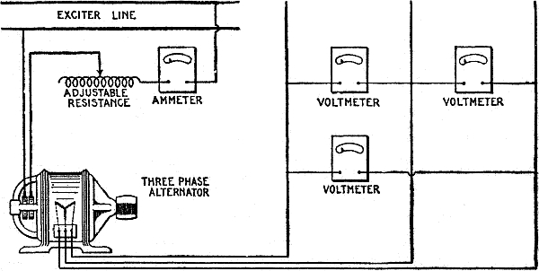
Fig. 2,887.—Alternator excitation or magnetization curve test. The object of this test is to determine the change of the armature voltage due to the variation of the field current when the external circuit is kept open. As here shown, the field circuit is connected with an ammeter and an adjustable resistance in series with a direct current source of supply. The adjustable resistance is varied, and readings of the voltmeter across the armature, and of the ammeter, are recorded. The speed of the generator must be kept constant, preferably at the speed which is given on the name plate. The excitation or magnetization curve of the machine is obtained by plotting the current and the voltage.
The resistance corresponding to the high reading scale is composed of copper wire having the same diameter as that constituting the resistance for the low reading scale, but as the capacity of the former scale is generally a whole number of times greater than that of the latter scale, the resistances for the two must bear the same proportion.
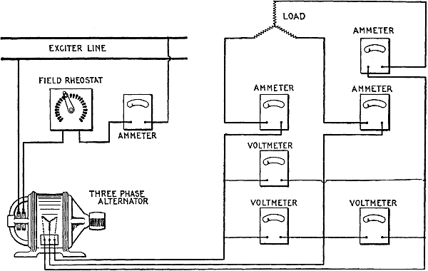
Fig. 2,888.—Three phase alternator synchronous impedance test. In determining the regulation of an alternator, it is necessary to obtain what is called the synchronous impedance of the machine. To obtain this, the field is connected, as shown above. Voltmeters are removed and the armature short circuited with the ammeters in circuit. The field current is then varied, the armature driven at synchronous speed, and the armature current measured by the ammeters in circuit. The relation between field and armature amperes are then plotted. The combination of the results of this test, with those obtained from the test shown in fig. 2,887, are used in the determination of the regulation of an alternator. Engineers differ widely in the application of the above to the determination of regulation, and employ many empirical formulae and constants for different lines of design.
Ques. How is a two scale voltmeter connected?
Ans. In the connection of a two scale voltmeter in circuit, the single binding post is always employed regardless of which scale is desired. If, then, the voltage be such that it may be measured on the low reading scale, the other binding post employed is that connected to the lower of the two resistances contained within; if, however, the pressure be higher than those recorded on the low reading scale, the binding post connected to the higher of the two resistances contained within is used.
NOTE.—Three phase alternator load test. By means of the connection shown in fig. 2,888, readings of armature current and field amperes can be obtained with any desired load. The field current can be varied also so as to maintain constant armature voltage irrespective of load; or the field current may be kept constant and the armature voltage allowed to vary as the load increases. The connections may also be used to make a temperature test on the alternator by loading it with an artificial load. In some cases after the alternator is installed the connection may be used to make a temperature test, using the actual commercial load the alternator is furnishing.
Inasmuch as the capacities of the scales are usually marked on or near the corresponding binding posts, there will generally be no difficulty in selecting the proper one of the two left hand binding posts.
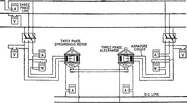
Fig. 2,889.—Three phase alternator or synchronous motor temperature test. In this test two alternators or synchronous motors of same size and type are used, and are belted together, one to be driven as a synchronous motor and the other as an alternator. The method employed is to synchronize the synchronous motor with the alternator or alternators on the three phase circuit, and then connect to the line by means of a three pole single throw switch. The alternator is then similarly synchronized with the alternator of the three phase circuit and thrown onto the line. By varying the field of the alternator it can be made to carry approximately full load, and the motor will then be also approximately fully loaded. The usual method is to have the motor carry slightly in excess of full load, and the alternator slightly less than full load. Under these conditions the motor will run a little warmer than it should with normal load, while the alternator will run slightly cooler. Temperature measurements are made in the same way as discussed under three phase motors. The necessary ammeters, voltmeters and wattmeters for adjusting the loads on the motors and generator are shown in above figure. If pulleys be of sufficient size to transmit the full load, with, say one per cent. slip, the pulley on the motor should be one per cent. larger in diameter than the pulley on the alternator, so as to enable the alternator to remain in synchronism and at the same time deliver power to the circuit. With very large machines under test, it is inadvisable to use the above method as it is sometimes difficult to so adjust the pulleys and belt tension that the belt slip will be just right to make up for the difference in diameter of the pulleys, and very violent flapping of the belt results. To meet such cases, various other methods have been devised. One which gives consistent results is shown in fig. 2,890.
Ques. How is a two scale voltmeter connected when the binding posts are not marked?
Ans. If only an approximate idea is possessed of the voltage to be measured, it is always advisable to connect to the binding post corresponding to the high reading scale of the meter in order to determine if the measurement may not be made safely and more accurately on the low reading scale. In any case, some knowledge must be had of the voltage at hand, else the high reading portion of the instrument may be endangered.
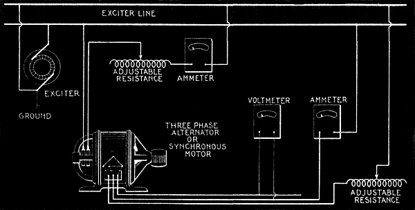
Fig. 2,890.—Three phase alternator or synchronous motor temperature test. Supply the field with normal field current. The armature is connected in open delta as illustrated, and full load current sent through it from an external source of direct current, care being taken to ground one terminal of the dynamo so as to avoid danger of shock due to the voltage on the armature winding. The field is then driven at synchronous speed. If the armature be designed to be connected star for 2,300 volts, the voltage generated in each leg of the delta will be 1,330 volts, and unless one leg of the dynamo were grounded, the tester might receive a severe shock by coming in contact with the direct current circuit. The insulation of the dynamo would also be subjected to abnormal strain unless one terminal were grounded. By the above method the field is subjected to its full copper loss and the armature to full copper loss and core loss. Temperature readings are taken as per standardization rules of the A.I.E.E. This method may also be used with satisfactory results on large three phase motors of the wound rotor type. If the alternator pressure be above 600 volts, a pressure transformer should be used in connection with the voltmeter.
Too much care cannot be taken to observe these precautions whenever the voltmeter is used, for the burning out or charring of the insulation either in the fine wire coil or in the high resistance of the meter by an excessive current, is one of the most serious accidents that can befall the instrument.
If a voltmeter has been subjected to a voltage higher than that for which it was designed, yet not sufficiently high to injure the insulation, but high enough to cause the pointer to pass rapidly over the entire scale, damage has been done in another way. The pointer being forced against the side of the case in this manner, bends it more or less and so introduces an error in the readings that are afterward taken.
The same damage will be done if the meter be connected in circuit so the current does not pass through it in the proper direction, although in this case the pointer is not liable to be bent so much as when it is forced to the opposite side of the meter by an abnormal current, since then it has gained considerable momentum which causes a severer impact. The extent of the damage may be ascertained by noting how far away from the zero mark the pointer lies when no current is passing through the instrument. If this distance be more than two-tenths of a division, the metal case enclosing the working part should be removed and the pointer straightened by the careful use of a pair of pinchers.
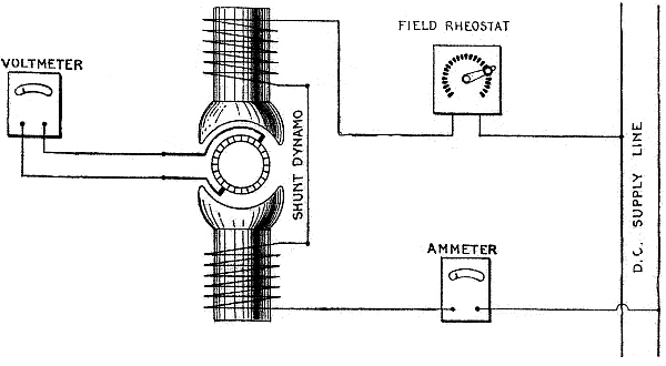
Fig. 2,891.—Direct motor or dynamo magnetization test. The object of this test is to determine the variation of armature voltage without load, with the current flowing through the field circuit. The armature should be driven at normal speed. The adjustment resistance in the field circuit is varied and the voltage across the armature measured. The curve obtained by plotting these two figures is usually called magnetization curve of the dynamo. It is usual to start with the higher resistance in the field circuit so that very small current flows, gradually increasing this current by cutting out the field resistance. When the highest no load voltage required is reached, the field current is then diminished, and what is called the descending (as opposed to the ascending) magnetization curves are obtained. The difference in the two curves is due to the lag of the magnetization behind the magnetizing current, and is caused by the hysteresis of the iron of the armature core.
Ques. What should be noted with respect to location of instruments?
Ans. If they be placed near conductors carrying large currents, the magnetic field developed thereby will produce a change in the magnetism of the instruments and so introduce an error in the readings.
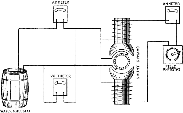
Fig. 2,892.—Shunt dynamo external characteristic test. The external characteristic of a shunt dynamo is a curve showing the relation between the current and voltage of the external circuit. This is obtained by the connection as here shown. The shunt field is so adjusted that the machine gives normal voltage when the external circuit is open. The field current is then maintained constant and the external current varied by varying the resistance in the circuit. By plotting voltage along the vertical, against the corresponding amperes represented along the horizontal, the external characteristic is obtained.
Ques. How should portable instruments be wired?
Ans. The wires must be firmly secured to the supports on which they rest, so as to reduce the possibility of their being pulled by accident, and so causing the instruments to fall.
A fall or a rough handling of the meter at once shows its effect on the readings, for as much harm is done as would result from a similar treatment of a watch.
The hardened steel pivots used in all high grade voltmeters are ground and polished with extreme care so as to secure and maintain a high degree of sensitiveness. The jewels on which the moving parts revolve are of sapphire, and they too must necessarily be made with skill and carefulness; if, therefore, the jewels become cracked and the pivots dulled by careless handling, the meter at once becomes useless as a measuring instrument.
Ques. How should readings be taken?
Ans. The deflection of the pointer should be read to tenths of a division; this can be done with considerable accuracy, especially after a little practice.
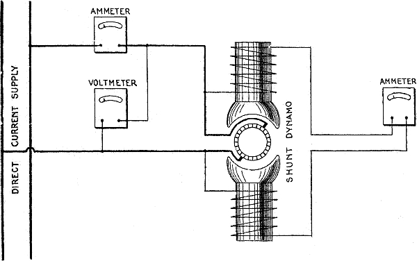
Fig. 2,893.—Load and speed test of direct current shunt motor. The object of this test is to maintain the voltage applied to the motor constant, and to vary the load by means of a brake and find the corresponding variation in speed of the machine and the current drawn from the circuit. If the motor be a constant speed motor, the field resistance is maintained constant. The above indicates the method of connecting instruments for the test alone; for starting the machine the ordinary starting box, should, of course, be inserted.
For very accurate results, a temperature correction should be applied to compensate the effect which the temperature of the atmosphere has upon the resistance of the meter when measurements are being taken. In ordinary station practice the temperature correction is negligible, being for resistance corresponding to the high scale in first class meters, less than one-quarter of 1 per cent. for a range of 35 degrees above or 35 degrees below 70 degrees Fahrenheit.
Ques. What attachment is sometimes provided on station voltmeters used for constant pressure service?
Ans. A normal index.
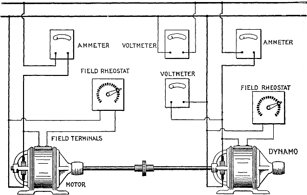
Fig. 2,894.—Temperature test of direct current motor or dynamo; loading back method. In making temperature tests on a small dynamo it is usual to drive the dynamo with a motor and load the dynamo by means of a lamp bank or resistance, the voltage across the dynamo being maintained constant, and the current through the external circuit adjusted to full load value. The temperatures are then recorded, and when they reach a constant value above the temperature of the atmosphere, the test is discontinued. Similarly, in making a test on a small motor, the motor is loaded with a dynamo and the load increased until the input current reaches the normal full load value of the motor, the test being conducted as for a small dynamo. When, however, the apparatus, either motor or dynamo, reaches a certain size, it becomes necessary, in order to economize energy, to use what is called the loading back method, as here illustrated. The motor is started in the usual way, with the dynamo belted to it, the circuit of the dynamo being open. The field of the dynamo is then adjusted so that the dynamo voltage is equal to that of the line. The dynamo is then connected to the circuit and its field resistance varied until it carries normal full load current. Under these conditions, if the motor and dynamo be of the same size and type, the motor will carry slightly in excess of full load, the difference being approximately twice the losses of the machines. Under these conditions the total power drawn from the line is equal to twice the loss of either machine. Temperature readings are taken as in other temperature tests.
Ques. What precaution must be taken in connecting station voltmeters?
Ans. Care must be taken to guard against any short circuiting of the voltmeter, which, would mean a short circuiting of the generator, and as a result the probable burning out of its armature.
The high resistance of the voltmeter prevents any such occurrence when it is connected in the proper way, but should one side of the circuit be grounded to the metal case or frame of the meter, a careless handling of the lead connected with the other side of the circuit would produce the result just mentioned.
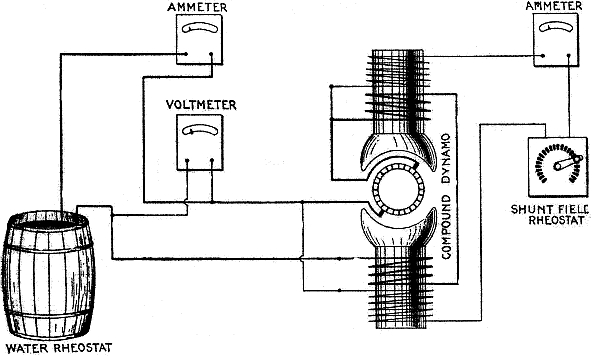
Fig. 2,895.—Compound dynamo external characteristics test; adjustable load. The object of this test is to determine the relation between armature voltage and armature current. Shunt field is adjusted to give normal secondary voltage when the external circuit is open. The load is then applied by means of an adjustable resistance or lamp bank, and readings of external voltage and current recorded. If the machine be normally compounded, the external voltage will remain practically constant throughout the load range. If the machine be under-compounded, the external voltage will drop with load, while if over-compounded, there will be a rise in voltage with increase in load.
Ques. Why do station voltmeters indicate a voltage slightly lower than actually exists across the leads?
Ans. Since they are usually connected permanently in circuit; a certain amount of heat is developed in the wiring of the instrument.
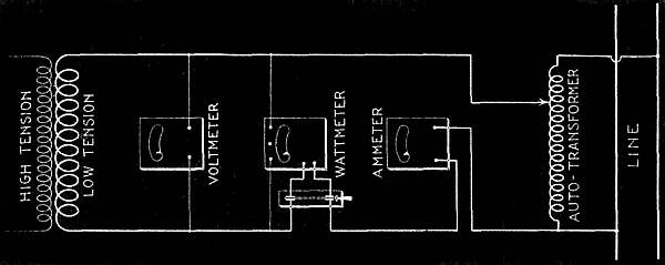
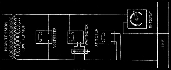
Figs. 2,896 and 2,897.—Transformer core loss and leakage, or exciting current test. With the primary circuit open, the ammeter indicates the exciting or no load current. It should be noted that all instruments are inserted on the low voltage side, for both safety of the operator and because the measurements are more accurate. The no load primary current, if the ratio of transformation be 10: 1, will be one-tenth of the measured secondary current. The wattmeter connected, as shown, measures the sum of the losses, in the transformer, in the pressure coil of the wattmeter, and in the voltmeter. On all standard makes of portable instruments, the resistance of the wattmeter pressure coil and of the voltmeter is given, and the loss in either instrument is the square of the voltage at its terminals, divided by its resistance. Subtracting these losses from the total indicated upon the wattmeter, gives the true core or iron loss. It should be noted that in this diagram is shown an auxiliary transformer with a number of taps for obtaining the exact rated voltage of the transformer under test. In fig. 2,897 is shown, in general, the same connections as in fig. 2,896, except that the auto-transformer has been replaced by a resistance. If the line voltage available be not much in excess of the rated voltage of the transformer under test, very little error is introduced by the use of the resistance method. However, if the difference be 10 per cent. or more the auxiliary transformer shown in fig. 2,896 should be used. Measurements made under the resistance method always give lower results than those obtained with the auxiliary transformer.
The effect of this heat increases the voltmeter resistance and consequently reduces the current below that which otherwise would pass through the meter; since the deflections of the pointer are governed by the strength of the current, station voltmeters invariably indicate a voltage slightly lower than that which actually exists across their leads.
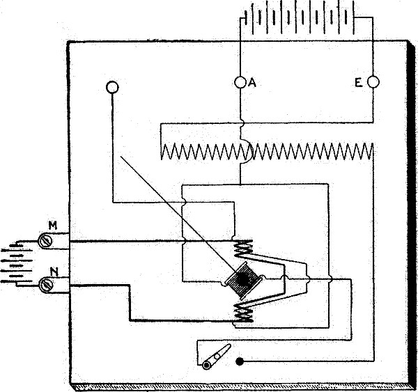
Fig. 2,898.—Diagram of connections for calibrating a wattmeter. The calibration of a portable wattmeter is accomplished with direct current of constant value which is passed through the series winding by connecting the source thereof with the current terminals. A direct current voltage which may be varied throughout the range of the wattmeter is also applied to the instrument between the middle and right hand pressure terminals A and E the wiring in the meter between these terminals being such that its differential winding is then cut out of circuit. The method of procedure consists in comparing the deflections on the wattmeter at five of six approximately equidistant points over its scale with the corresponding products of volts and amperes used to obtain them. The changes in the wattmeter deflections are effected by merely varying the voltage, the value of the current being maintained constant at a value which represents the full current capacity of the meter.
NOTE.—Checking up of a recording wattmeter. This may conveniently be done by noting the deflections at short intervals on an ammeter connected in circuit, and also the readings on the dial of the recording wattmeter during this period. If this test be continued for an appreciable time, the product of the pressure in volts, the current in amperes, and the time in hours, should equal the number of watthours recorded on the counters of the dial.
NOTE.—Transformer testing. In the early days of transformer building, before the commercial wattmeter had been perfected, leakage or exciting current was the criterion of good design. After the introduction of the wattmeter, core loss became the all important factor, and for a long time the question of leakage current was lost sight of. With the introduction of silicon steel, leakage or exciting current again assumed prominence. Keeping in mind the fact that all characteristics of a transformer are of more or less importance, it is essential that the user of such apparatus have at hand the necessary facilities for making tests of all such variable quantities. The tests which all users of transformers should make, are given in this chapter.
Ques. Can direct current be measured by an alternating current voltmeter?
Ans. Yes.
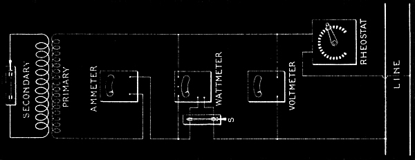
Fig. 2,899.—Transformer copper loss by wattmeter measurement and impedance. At first glance, this method would seem better than the calculation of loss after measurement of the resistance. However, it should be noted that the wattmeter is, in itself, subject to considerable error under the low power factor that will exist in this test. The secondary of the transformer is short circuited, and a voltage applied to the primary which is just sufficient to cause full load primary current. If full current pass through the primary of the transformer with the secondary short circuited, the secondary will also carry full load current. With connections as shown, and with the full load current, the voltmeter indicates the impedance volts of the transformer. This divided by the rated voltage gives what is called the per cent. impedance of the transformer. In a commercial transformer of 5 kw., this should be approximately 3 per cent. The iron loss of the transformer under approximately 3 per cent. of the normal voltage will be negligible, and the losses measured will be the sum of the primary and secondary copper losses. As in the discussion of the core loss measurements, the wattmeter readings must be corrected for the loss in its pressure coil, the method of correction being the same as that discussed under the core loss measurement. If the impedance volts, as measured, be divided by the primary current, the impedance of the transformer is obtained. The reciprocal of this quantity is known by the term "admittance." When two or more transformers are connected in parallel they divide the load in proportion to their admittance. It is, therefore, important that the users of transformers know the impedance of the apparatus used, in order to determine whether two or more transformers will operate satisfactorily in parallel. For discussion of wattmeter error on low power factor, see note on page 2,075. For accurate measurement of impedance, the voltmeter should be connected directly across the terminals of the transformer rather than as shown in the diagram.