Chapter LXVII · MANAGEMENT (continued 3)
Reading edition
NOTE.—Transformer copper loss test. The usual and best method of obtaining copper losses is to separately measure the primary and secondary resistance and calculate from these the primary and secondary copper losses. For general diagram of connections and discussion of the drop method, see fig. 2,875. The current should be kept well within the load current of the transformer to avoid temperature rise during the test. In other words, the resistance of the coil is the voltage across its terminals divided by the current. The resistance of the primary coil can be measured similarly. The copper loss in watts in each coil will then be the product of the resistance and the square of the rated current for that coil. The total copper loss will be the sum.
Ques. What would be the effect of placing a direct voltmeter across an alternating current circuit, and why?
Ans. There would be no deflection of the pointer owing to the rapid reversals of the alternating current.
Ques. What are the usual capacities of alternating current voltmeters?
Ans. They are 3, 7.5, 10, 12, 15, 20, 60, 75, 120, 150, 300 and 600 volts, but these capacities may each be increased by the use of a multiplier.
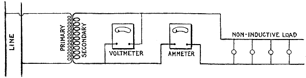
Fig. 2,900.—Temperature test of transformer with non-inductive load. The figure shows the simplest way of making the test. Connect the primary of the transformer to the line as shown, and carry normal secondary load by means of a bank of lamps or other suitable resistance, until full load secondary current is shown by the ammeter in the secondary circuit. The transformer should then be allowed to run at its rated load for the desired interval of time, temperature readings being made of the oil in its hottest part, and also of the surrounding air. Where temperatures of the coil rather than temperatures of the oil are desired, it is necessary to use the resistance method. This is obtained by first carefully measuring the resistance of both primary and secondary coils at the temperature of the room, and then, after the transformer has been under heat test for the desired time, disconnect it from the circuit and again measure the resistance of primary and secondary. For proper method of calculating the temperature rise from resistance measurements, the reader is referred to the standardization rules of the A.I.E.E. In making resistance measurements of large transformers by the drop method care should be taken to allow both ammeter and voltmeter indications to settle down to steady values before readings are taken. This may require several minutes. Each time the current is changed it is necessary in order to obtain check values on resistance measurements, to wait until the current is again settled to its permanent value before taking readings. All resistance measurements must be taken with great care, as small errors in the measurement of the resistance may make very large errors in the determination of the temperature rise. The method above described is satisfactory for small transformers. Where large units are to be tested, the cost of current for testing becomes an important item. The "bucking test" as in fig. 2,901, is more economical.
Ques. How are station voltmeters usually attached to the switchboard?
Ans. They are usually bolted to the switchboard by means of four iron supports mounted on the back of the instrument; two of these are fastened near each side of the case.
Under certain conditions, however, as in paralleling of alternators, it is convenient to have the alternating current voltmeter mounted on a swinging bracket at the side of the switchboard. The voltmeter may then be swung around in any desired direction so as to enable the attendant to keep informed of the voltage while switching in each additional alternator.
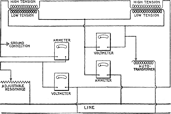
Fig. 2,901.—Transformer temperature "bucking test." For this purpose two transformers of the same size and ratio are required. The connections are as shown. Full secondary voltage is applied, and rheostats or auxiliary auto-transformers are inserted in the circuit to properly regulate the voltage. The primaries are connected with one bucking the other, and a voltage equal to twice the impedance voltage of either transformer inserted in the primary circuit. It should be noted that when the secondaries are subjected to the full secondary voltage, a full primary voltage exists across either primary, but with the primaries connected so that the voltage of one is bucked against the voltage of the other, the resultant voltage in the circuit will be zero. By applying to the primary circuit twice the impedance voltage of either transformer, full primary and secondary current will circulate through both transformers. On the other hand, by subjecting the secondaries to the full secondary voltage, the iron of the transformer will be magnetized as under its regular operating conditions, and the full iron loss of the transformer introduced. This method permits the operation of two transformers under temperature test with their full losses, without taking energy from the line equal to the rated capacity. Measurements of temperature are taken in exactly the same way as above. This method is successfully employed for making temperature tests on transformers of all sizes.
Ques. How should an ammeter be operated to get accurate readings, and why?
Ans. It should be cut out of circuit except while taking a reading, because of the error introduced by the heating effect of the current.
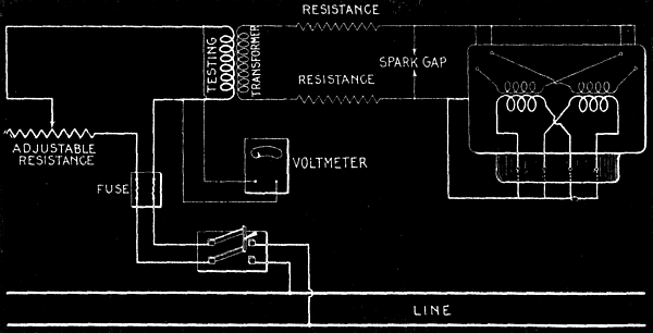
Fig. 2,902.—Transformer insulation test. In applying a 10,000 volt insulation test between the primary and secondary of a transformer, the testing leads should be disconnected from the transformer under test, and a spark gap introduced as shown, with the test needle set at a proper sparking distance for 10,000 volts. A high resistance should be connected in the secondary before closing its circuit, and the voltage gradually increased by cutting out this secondary resistance until a spark jumps across the spark gap. When the spark jumps across the spark gap, the voltmeter reading should be recorded and the testing transformer disconnected. The spark gap should then be increased about 10 per cent. and the high tension leads connected to the transformer under test as indicated in the diagram. In order to equalize the insulation strains, all primary leads should be connected together, all secondary leads not only connected together, but to the core as well. All resistance in the rheostat in the low tension circuit should then be inserted and the switch closed. Gradually cut out secondary resistance until the voltmeter shows the same voltage as was recorded previously when the spark jumped across the gap, and apply this voltage to the transformer for one minute. Insulation tests for a period of over one minute are very unadvisable, as transformers with excellent insulation may be seriously damaged by prolonged insulation tests. The longer the strain to which any insulation is subjected, the shorter the subsequent life of the insulation. Also the greater the applied voltage above the actual operating voltage of the apparatus, the shorter the subsequent life of the insulation. In testing small transformers, the spark gap may be omitted and the voltage of the low pressure coil of the testing transformer measured. This multiplied by the ratio of transformation gives the testing voltage.
In an ammeter having a capacity of 50 amperes, the error thus introduced will be less than 1 per cent. if connected continuously in circuit with a current not exceeding three-quarters this capacity.
An ammeter of 100 amperes capacity may be used indefinitely in circuit with less than 1 per cent. error up to one-half its capacity, and for five minutes at three-quarters capacity without exceeding the 1 per cent. limit.
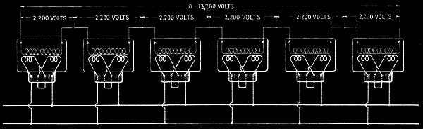
Fig. 2,903.—Transformer insulation test as made when a special high tension transformer be not available. In this method a number of standard transformers, connected as shown may be employed, but great care should be taken to have such transformer cases thoroughly insulated from the ground and from one another, in order to minimize the insulation strains in the testing transformers. Care should be taken to insert in the circuit of each testing transformer a fuse, not in excess of the transformer capacity, which will blow, in case of a break down in the apparatus under test. In testing insulation between secondary and core, disconnect the primary entirely, apply one terminal of the testing transformer to the secondary terminals of the transformer under test, and the other terminal of the testing transformer to the core of the transformer under test. This test should also not be in excess of one minute.
The 150 scale ammeter may be left in circuit for an indefinite length of time at one-third its full capacity, and for three minutes at one-half its full capacity, with a negligible error.
Ammeters of 200 and of 300 ampere capacities must not continuously carry more than one-quarter of these loads respectively if the readings are to have an accuracy within 1 per cent. nor more than one-half these respective number of amperes for three minutes if the same degree of accuracy be desired.
In order to cut or shunt the ammeter out of circuit when not in use, it is customary when wiring the instrument in place, to introduce a switch as a shunt across it; this switch is kept closed except when a measurement is being taken.
When currents larger than 300 amperes have to be measured, ammeter shunts are generally employed, although ammeters up to 500 amperes capacity are manufactured.
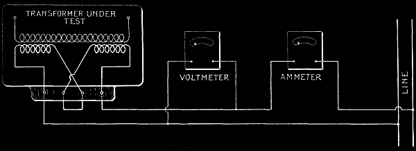
Fig. 2,904.—Transformer internal insulation test, sometimes called double normal voltage test, from the fact that most transformers are tested with double normal voltage across their terminals. If either the primary or secondary of the transformer be connected to some source of current with voltage double that of the voltage of the transformer under test, the insulation between adjacent turns, and also the insulation between adjacent layers will be subjected to twice the normal operating voltage. It is good practice to employ high frequency for this test in order to prevent an abnormal current from passing through the transformer. Sixty cycle transformers are usually tested on 133 cycles, and 25 cycle transformers on 60 cycle circuits for this double normal voltage test. It is necessary to insert the resistance in the circuit of the transformer and bring the voltage up gradually, the same as applying other high insulation tests in order to prevent abnormal rises in pressure at the instant of closing the circuit.
Ques. What is used in place of instrument shunts for high pressure alternating current measurements?
Ans. Instrument transformers.
Ques. What important attention should be periodically given to measuring instruments?
Ans. They should be frequently tested by comparison with standards that are known to be correct.
Electrical measuring instruments, owing to the nature of their construction and the conditions under which they must necessarily be used, are subject to variations in accuracy. This feature is an annoying one on account of the difficulty of detecting it; a meter may, as far as appearances go, be in excellent working order and yet give readings which are not to be relied upon.
Ridiculous as it may appear, the average station attendant may frequently be seen straining his eyes to read to tenths of a division on the scale of a meter which, if subjected to test, would show an inaccuracy of over 2 per cent.
In testing a meter, by comparing it with a standard, in order to obtain the best results there should be one man at each meter so that simultaneous readings may be taken on both instruments, and the man at the standard meter should maintain the voltage constant while a reading is being taken, by means of a rheostat in the field circuit of the generator supplying the current.
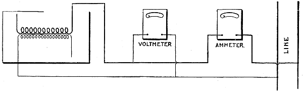
Fig. 2,905.—Transformer insulation resistance test. The insulation, besides being able to resist puncture, due to increased voltage, must also have sufficient resistance to prevent any appreciable amount of current flowing between primary and secondary coils. It is, therefore, sometimes important that the insulation resistance between primary and secondary be measured. This can be done, as here shown. Great care should be taken to have all wires thoroughly insulated from the ground, and to have an ammeter placed as near as possible to the terminals of the transformer under test, in order that current leaking from one side of the line to the other, external to the transformer, may not be measured. Great care is required in making this measurement, in order to obtain consistent results.]
Each meter should be checked or calibrated at five or six approximately equidistant points over its scale; the adjustable resistance being varied each time to give a deflection on the standard meter of an even number of divisions and the deflection on the other meter recorded at whatever it may be. Having obtained the necessary readings, the calculation of the constant or multiplying factor of the meter undergoing test is next in order.
This may best be shown by taking an actual case in which a 150 scale voltmeter is being tested to determine its accuracy. The data and calculations are as follows:
Readings on standard meter Readings on meter tested Constant
150 149.2 150 ÷ 149.2 = 1.005
125 125.0 125 ÷ 125.0 = 1.000
100 98.9 100 ÷ 98.9 = 1.011
75 73.6 75 ÷ 73.6 = 1.019
50 50.0 50 ÷ 50.0 = 1.000
25 24.8 25 ÷ 24.8 = 1.008
6.043
Average constant for six readings, 6.043 ÷ 6 = 1.007.
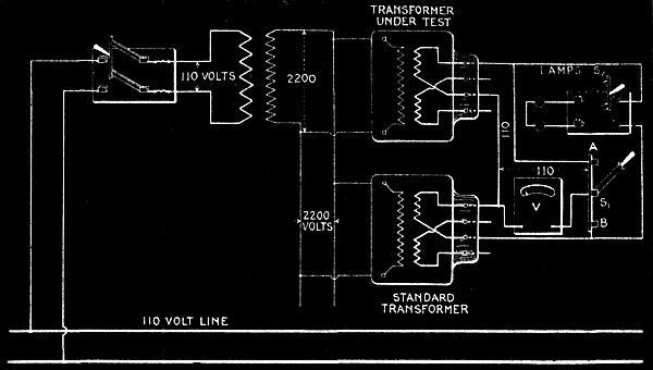
Fig. 2,906.—Transformer winding or ratio test. The object of this test is to check the ratio between the primary and the secondary windings. For this purpose a transformer of known ratio is used as a standard. Connect the transformer under test with a standard transformer as shown. Leave switch S2 open. With the single pole double throw switch in position S1B, the voltmeter is thrown across the terminals of the standard transformer. With the switch in position S1A, the voltmeter is thrown across the terminals of the transformer under test. The voltmeter should be read with the switch in each position. If the winding ratio be the same as that of the standard transformer, the two voltmeter readings will be identical.
It may be stated in general that before taking the readings for this test, the zero position of the pointer on the meter tested should be noted, and if it be more than two-tenths of a division off the zero mark, the case of the meter should be removed and the pointer straightened.
Furthermore, it will be noticed from the readings here recorded that the test is started at the high reading end of the scale; this is done in order that the pointer may gradually be brought up to this spot, by slowly cutting out of circuit the adjustable resistance, and thus show whether or not the pointer has a tendency to stick at any part of the scale. If the meter seem to be defective in this respect, it should be remedied either by bending the pointer or scale, or by renewing one or both of the jewels, before the comparison with the standard is commenced.
It is obvious from the readings recorded for the 150 scale voltmeter, that as compared with the corresponding deflections of the standard, the former are a trifle low.
In order to determine for each observation how much too low they are, it is necessary to divide each reading on the standard by the corresponding reading on the meter tested. The result is the amount by which a deflection of this size on the meter tested must be multiplied in order to obtain the exact reading. This multiplier is called a constant, and as shown, a constant is determined for each of the six observations.
The average constant for the six readings is then found, and this is taken as the constant for the meter as a whole; that is, whenever this 150-scale voltmeter is used, each reading taken thereon must be multiplied by 1.007 in order to correct for its inaccuracy.
The most convenient and systematic way of registering the constant of a meter is to write it, together with the number of the meter and the date of its calibration, in ink on a cardboard tag and loop the same by means of a string to the handle or some other convenient part of the meter.
NOTE.—Transformer polarity test. A test of importance in the manufacture of transformers, and sometimes necessary for the user, is the so called banking or polarity test. The transformers from any particular manufacturer have the leads brought out in such a manner that a transformer of any size can be connected to primary and secondary lines in a given order without danger of blowing the fuses due to incorrect connections. All manufacturers of transformers, however, do not bank transformers in the same way, so that it is necessary in placing transformers of different makes to test for polarity. This is done as shown in fig. 2,906. One transformer is selected as a standard and the leads of the second transformer connected as indicated in the diagram. If the transformers be 1,100-2,200 volts to 110-220, two 110 volt lamps are connected in the secondaries of the transformers as indicated, while the primary of the transformer is connected across the line. In transformers built for two primary and two secondary voltages, it is necessary to test each primary and each secondary. The diagram shows the method of connecting one 2,200 volt coil and one 110 volt coil to the transformer to be tested. When the primary circuit of the transformer under test is closed, and if the secondary leads of the 110 volt coil under test be brought out of the case properly, the two 110 volt lamps should be brightly illuminated. If, on the other hand, the two 110 volt terminals have been reversed, no current will flow through the lamps. If these two terminals be found to be brought out correctly, transfer the secondary leads of the transformer under test to the second 110 volt coil. Upon closing the primary circuit, the lamp should again be brightly illuminated. Repeat this process with each of the secondary coils and the other primary coil, and if the lamps show up brightly in every case on closing the primary circuit, all leads have been properly brought out. If on any tests the lamps do not light up brightly, the leads on the transformer must be so changed as to produce the proper banking.
Ques. What are the usual remedies applied to a voltmeter to correct a 3 or 4 per cent. error?
Ans. They consist of straightening the pointer, varying the tension of the spiral springs, renewing the jewels in the bearings, altering the value of the high resistance, and, in the case of a direct current instrument, strengthening the permanent magnet.
Ques. How is the permanent magnet strengthened?
Ans. After detaching it from the instrument, wrap around several turns of insulated wire, and pass through this wire for a short time 3 or 4 amperes of direct current in such a direction as to reinforce the magnet magnetism.
Ques. How may the value of the high resistance of a voltmeter be altered?
Ans. Determine the resistance of the voltmeter and add or subtract, according as the reading is high or low, a certain length of wire whose resistance is in per cent. of the voltmeter resistance the same as the per cent. of error.
NOTE.—The complete calibration of a two scale voltmeter does not, as might be supposed, necessitate that the readings on both scales be checked with standards, for since the resistance corresponding to the one scale is always some multiple of the resistance of the other, the constants of the two scales are proportional. For instance, if S = the reading at the end of the high scale of the voltmeter; S1 = the reading at the end of the low scale of the voltmeter; R = the resistance in the meter corresponding to the high scale; R1 = the resistance in the meter corresponding to the low scale; K = the constant for the high scale, and K1 = the constant for the low scale. Then
SK ÷ R = S1K1 ÷ R1
from which
K1 = SKR ÷ S1R
That is to say, if the respective resistances corresponding to the two scales be known, and the constant of the high scale be determined by comparison with a standard, then by aid of these known values and the maximum readings on the two scales, the constant of the low scale may be calculated. It is also possible to calculate the constant of the high scale if the constant of the low scale be known, together with the values of the resistances corresponding to the two scales; for from the equation previously given.
K = RS1K1 ÷ R1S
Ques. What is a frequent cause of error in an alternating current meter, and why?
Ans. The deterioration of its insulation, which permits the working parts of the instrument coming in contact with the surrounding metal case.
A convenient method of testing for deterioration of insulation is shown in fig. 2,905.
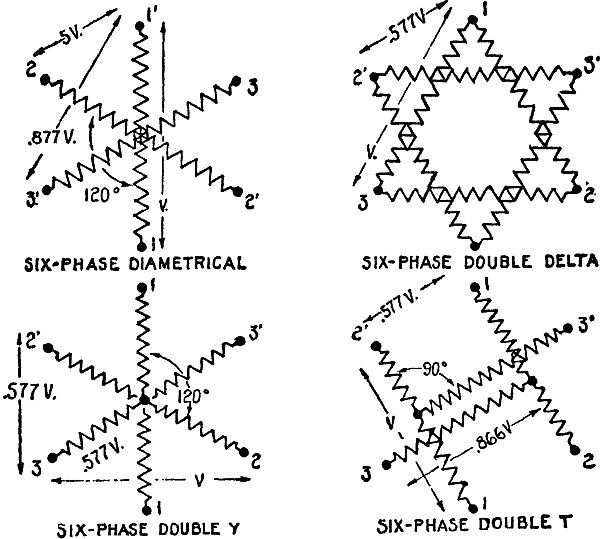
Fig. 2,907.—Diagrams showing various synchronous converter transformer connections. The diametrical connection is used most frequently as it requires only one secondary coil on each transformer, this being connected to diametrically opposite points on the armature winding. The middle points can be connected together and a neutral obtained the unbalanced three wire direct current having no distorting effect. With diametrical secondaries, the primaries should preferably be connected delta, except with regulating pole converters where they must be connected Y. Diametrical secondaries with delta primaries should not be used with regulating pole converters. Double star connection of secondaries may, however, be used with delta primaries, and is free from the trouble of the triple harmonic of the transformer appearing in the primary. In this case, however, the two secondary neutrals must not be connected with each other.
How to Test Generators.—In the operation of electrical stations, many problems dealing with the generators installed therein can be readily solved by the aid of characteristic curves, which bear a relation to the generators similarly as do indicator diagrams to steam engines.
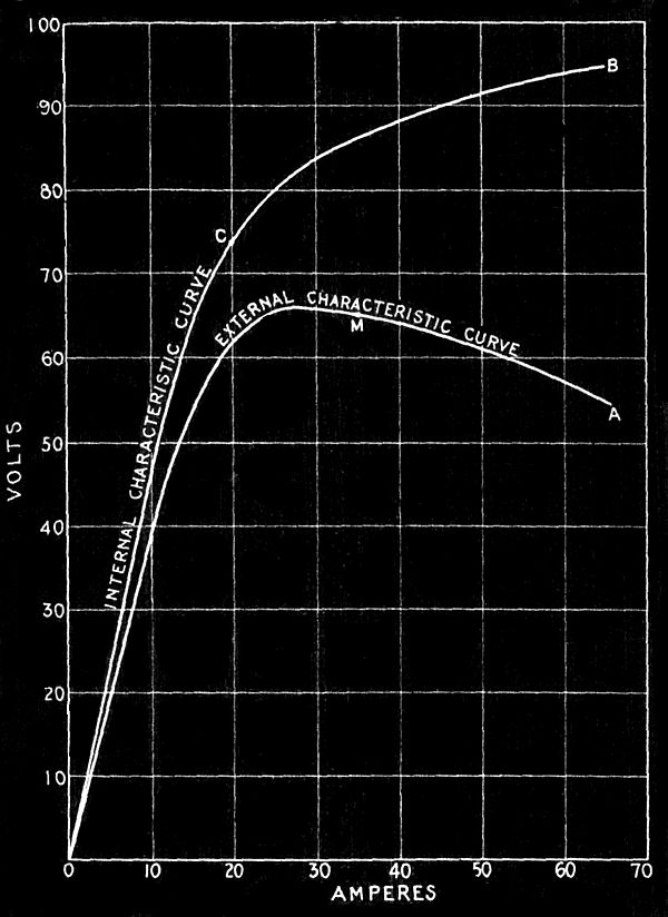
Fig. 2,908.—General form of characteristic curves for a series dynamo. The general curve that may be expected is OA. It is obtained practically in the same manner as for the shunt characteristic curve, except that no field rheostat is employed. Commencing with no load or amperes, there will probably be a small deflection noticeable on the voltmeter, due to the residual magnetism. The other readings are taken with successive reductions of main current resistance. The curve OA thus obtained for a certain series generator is practically a straight line at the beginning, representing thereby a proportional increase of voltage with increase of current, but after a certain current is reached (about 20 amperes in this case) the curve flattens and takes a downward direction. The turning point occurs in the characteristic curves of all series generators, and it denotes the stage at which the iron magnet cores become so saturated with lines of magnetic force that they will not readily allow more to pass through them; this turning point is technically known as the point of saturation, and the current corresponding (20 amperes in this case) is called the critical current of the dynamo. The point of saturation in any given series machine is governed by the amount of iron in the magnetic circuit; its position in the curve therefore varies according to the design of the generator as does also the critical current. The value of the latter is important inasmuch as the valuable features of a series generator assert themselves only when the machine is supplying a greater number of amperes than that of the critical current, for if the series generator be worked along that part M A of the curve to the right of the point of saturation it becomes nearly self-regulating as regards current, because as the current increases the voltage drops. In the diagram in addition to the characteristic curve O A, which may more definitely be called an external characteristic curve on account of representing the conditions external to the generator, there is shown a total characteristic curve, O C B. The latter curve represents the relation between the current and the total voltage developed in the armature, and may be plotted from the external characteristic curve if the resistance of the armature between brushes and the resistance of the series field winding be known. For example, assume these combined resistances amount to .6 ohm. At 30 amperes there would be required 30 × .6 = 18 volts to force this current through the armature and field windings. At 30 amperes the external pressure is 65 volts, as shown by the curve O A; the total voltage developed for 30 amperes is, therefore, the external voltage plus the internal voltage or 65 + 18 = 83 volts. Plotting 83 volts for 30 amperes will give one point for the external characteristic curve of this machine, and by determining in like manner the total voltages developed for six or eight different currents over the scale, sufficient data will be at hand for plotting and drawing in the curve O C B.
In steam engineering, a man who did not fully understand the method of taking an indicator diagram would be considered not in touch with his profession, and in electrical engineering the same would be true of one ignorant of the method of obtaining characteristic curves.
The necessary arrangement or connection of the generator from which it is desired to obtain a characteristic curve, consists in providing a constant motive power so that the machine may be run at a uniform speed, and when the field magnets of the generator are separately excited the field current from the outside source must also be maintained constant, preferably by a rheostat connected in the field of the auxiliary exciting machine. It is also necessary in every case that means be provided for varying the main current of the generator step by step from zero to maximum. This may best be done by employing a water rheostat, as shown in fig. 2,909.
Ques. What instruments are needed in making a test of dynamo characteristics?
Ans. A voltmeter, ammeter, speed indicator, the usual switches and rheostats.
Ques. How is the apparatus connected?
Ans. It is connected as shown in fig. 2,910.
Ques. Describe the test.
Ans. Having completed the preliminaries as in fig. 2,910, the test should be started with the main circuit of the generator open. Then, in the case of the shunt machine, the speed should be made normal and the field rheostat adjusted until the voltmeter reading indicates the rated voltage of the machine at no load and readings taken. The electrodes of the water rheostat should be adjusted for maximum resistance and main circuit closed, and a second set of readings taken. Several sets of readings are taken, with successive reductions of water rheostat resistance. The results are then plotted on coordinate paper giving the characteristic curve shown in fig. 2,908.
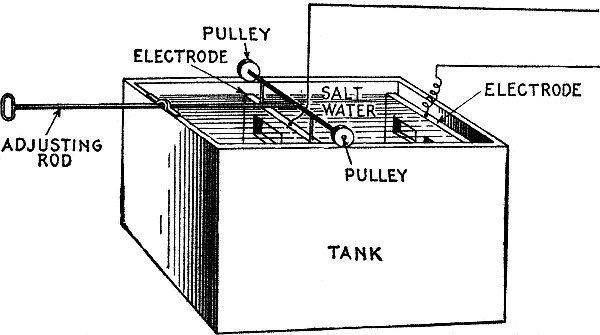
Fig. 2,909.—Water rheostat. It consists essentially of a tank of suitable size containing salt water into which are placed two electrodes having means of adjustment of the distance separating them. The solution depends on the voltage. Pure water is seldom used for pressures under 1,000 volts. The size of the tank is determined by the size of the electrodes, and roughly the size of the latter equal the number of amperes. With a current density of one ampere per square inch, a water solution gives a drop of 2,500 to 3,000 volts per inch distance between the plates. Where high voltage is used, the water must be circulated through and from the tank by rubber hose allowing for 2,500 volts, a length of 15 to 20 feet of 1 inch hose to prevent grounding. In place of the arrangement shown above, a barrel may be used for the tank, and for the electrodes, coils of galvanized iron wire. This is the simplest form and is satisfactory.
Ques. What does the characteristic curve (fig. 2,911) show?
Ans. An examination of the curve shows that the highest point of the curve occurs at no load or 0 amperes; that as the current is increased, the voltage drops, first slightly to the point B and then rapidly until the point E is reached, when any further lowering of resistance in the main circuit to increase the current causes not only a rapid decline in the voltage but also of the current until both voltage and current become approximately zero.
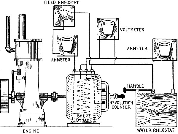
Fig. 2,910.—Connections for test of dynamo. During the test, one man should be assigned to the tachometer, another man to the water rheostat, and there should preferably be one man at each of the electrical measuring instruments. In order to enable the man at the tachometer to keep the speed constant, he should be in communication either directly or indirectly with the source of the driving power, and the man at the water rheostat should be in plain view of the man reading the ammeter so that the latter party may signal him for the proper adjustment of the rheostat in order that the desired increase of current be obtained for each set of readings.
In some generators, a very slight current results even when the terminals of the machine are actually short circuited; that is, due to residual magnetism in the pole pieces, the lower portion of the curve often terminates, not exactly at zero, but at a point some distance along the current line.
The working portion of the curve is from A to C, at which time the machine is supplying a fairly constant voltage. From C to E shows a critical condition of affairs, while the straight portion D O represents the unstable part of the curve caused by the field current being below its proper value.
The position of the point C determines the maximum power the machine is capable of developing, being in this case (47.5 × 25) ÷ 746 = 1.59 horse power.
Ques. How may the commercial efficiency of a generator be determined?
Ans. To obtain the commercial efficiency, the input and output must be found for different loads.
The input may be found by running the generator as a motor at its rated speed, loading it by means of a Prony brake. The generator must be stripped of all belting or other mechanical connections, supplied with its normal voltage and full load current, and the pressure of the Prony brake upon its armature shaft or pulley adjusted until the rated speed of the armature is obtained. The data thus obtained is substituted in the formula.
2π L W R
input in brake horse power = —————— (1)
33,000
in which L = length of Prony brake lever; W = pounds pull at end of lever; R = revolutions per minute.
The output or electrical horse power for the same load is easily calculated from the formula
amperes × volts
output in electrical horse power = ———————— (2)
746
After obtaining value for (1) and (2) the commercial efficiency for the load taken is obtained from the formula
output
commercial efficiency = ———— (3)
input
Having obtained the commercial efficiency, the difference between the ideal 100 per cent. and the efficiency found will be due to certain losses in the generator. These losses may be classified as
1. Mechanical. 2. Electrical.
The mechanical losses are the friction of the bearings and brushes, and air friction. The electrical losses consist of the eddy current loss, hysteresis loss, armature resistance loss, and field resistance loss.
In testing for these losses, the generator to be tested should be belted to a calibrated motor which latter machine should preferably be of the constant pressure, shunt wound type.
The friction of the bearings and belt of the generator are determined together by raising the brushes off its commutator and running it at the rated speed by means of the calibrated motor.
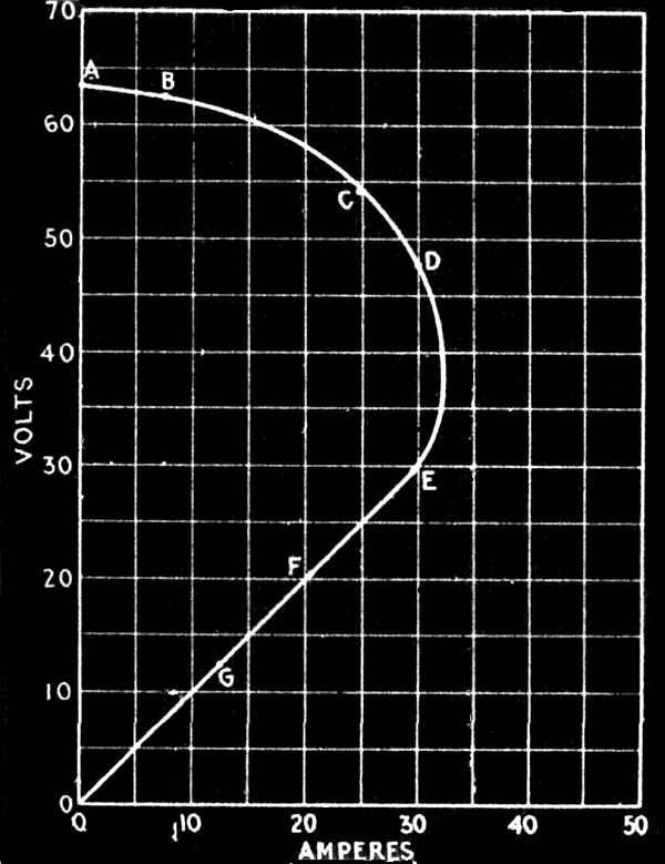
Fig. 2,911.—Characteristic curve of shunt dynamo. Suppose in making the test, the deflections on the meters for the first readings be 63 volts and 0 amperes, the plotting of these values will give the first point on the curve. Similarly, the second readings with main circuit closed and maximum resistance in the water rheostat may be assumed to be 62.5 volts and 7.5 amperes, which plotted gives the second point B. A still further lowering of the plate will permit a stronger current in the main circuit, and the value of this together with its corresponding voltage will give a third point for the curve. Neither for this reading, however, nor for the following readings of the test should the field rheostat be altered. When six or eight points ranging from zero to a maximum current have been obtained and plotted, a curved line should be drawn through them such as shown through ABCDEFG0, the characteristic curve of the dynamo. While the curve may be sketched in free hand, it should preferably be drawn by the aid of French curves. In case the French curve cannot be exactly made to coincide with all the points as for instance C and D, it should be run in between giving an average result, and smoothing out irregularities, or small errors due to the "personal equation." The meter of course must be correct or calibrated and the readings corrected by the calibration coefficient.
The amount of power as ascertained from the calibration curve of the motor for the voltage and current used therein when driving the generator as just explained, is a measure of these two losses. The power thus used is practically constant at all loads and is about 2 per cent. of that necessary to drive the generator at full load.
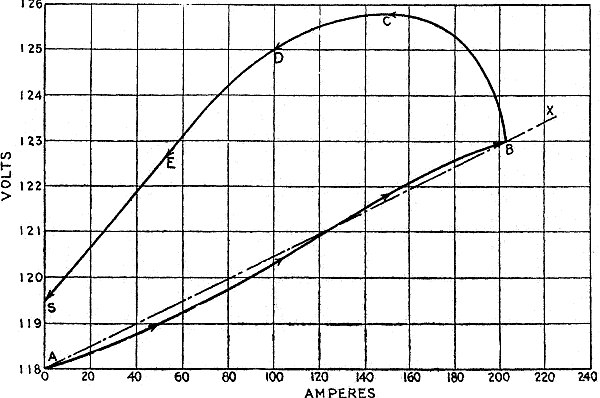
Fig. 2,912.—Characteristic curves for a compound dynamo. If the machine be over compounded, the characteristic curve has the form of the curve A B, which curve was obtained from a machine over-compounded from 118 to 123 volts, and designed to give 203 amperes at full load. The preliminary arrangements for testing a compound dynamo are similar to those for a shunt generator, and if the shunt across the series field winding be already made up and in position, the readings are taken precisely in the same manner. It is generally considered sufficient if observations be recorded at zero, ¼, ½, ¾ and full load. If it be desired to ascertain the effect which residual magnetism has upon the field magnets the current is decreased after the full load point is reached without opening the circuit, and readings are taken in succession at ¾, ½, ¼ and zero load giving in this case the curve B C D E S. It is thus seen that residual magnetism exerts no small effect upon the voltage obtained at the different loads, for had there been no residual magnetism in the field magnets the curve B C D E S would have coincided with the curve A B. The curve A B, and the straight line A X drawn through the points A and B, are almost identical, and as A X represents the theoretical characteristic curve for the machine, it is seen that compounding is practically perfect. In order to insure such accurate results being obtained, providing the machinery be correctly designed, requires considerable care in taking the readings; for example, each step or load on the ascending curve should not be exceeded before the corresponding deflection is taken, else the residual magnetism will cause the pressure reading to be higher than it actually should be, and the following pressure readings will also be affected in the same manner. In case the shunt to be employed across the series field has not been made up, it is advisable to perform a trial test before taking the readings for the curve as previously described. The trial test consists in taking two readings,—one at no load and the other at full load, the shunt being so adjusted as to length and section that the desired amount of compounding will be obtained in the latter reading with normal voltage at no load. If the first trial fail to produce the desired result by giving too low a voltage at full load, the length of the shunt across the series field should be increased, or its section should be reduced by employing a less number of strips in its makeup; again, if the voltage at full load be higher than that desired, there must be made a decrease in length or an increase of section in the shunt employed.
The friction of the brushes can very conveniently be determined next by lowering them on the commutator and giving them the proper tension.
The increase in power resulting from the greater current that will now be taken by the motor to run the dynamo at its rated speed, will be a measure of this loss. In general, its value will be about .5 per cent. of the total power required to drive the dynamo at full load, and this also will remain constant at all loads.
The friction of the air upon the moving armature of the dynamo cannot be determined experimentally, but theoretically this loss is small and may be estimated as .5 per cent.; it is also constant at all loads.
The core loss may be determined experimentally by exciting the field magnets of the dynamo with the normal full load field current through the magnet coils, and noting the increase of power required by the motor to maintain the rated speed of the dynamo thus excited under no load, over that necessary under the same conditions with no field excitation. This increase of power will be the value of the core loss. The core loss is approximately 3 per cent. of the power required to operate the dynamo at full load, and it is constant at varying loads. If it be desired to divide the core loss into its component parts, it is necessary also to run the dynamo under the same conditions as before with field excitation but at half its rated speed. If, then,
H = the power lost in hysteresis at rated speed, E = the power lost in eddy currents at rated speed, T = the power lost in hysteresis and eddy currents at rated speed, S = the power lost in hysteresis and eddy currents at half speed.
there may be formed the two following equations:
H E
T = H + E, and S = — + —,
2 2
from which the elimination of H will give E = 2T - 4S.
The value of the eddy current loss thus found will be about 1½ per cent., and constant at all loads.
Having previously ascertained the power lost in both eddy currents and hysteresis, and knowing now the power lost in eddy currents alone, it is easy to find that lost in hysteresis by simply subtracting the latter known value from the former. The value of the hysteresis loss is therefore approximately 1½ per cent., and it is constant at different loads.
There yet remains to be determined the armature resistance loss and the field resistance loss. As for the calibrated motor, this may be disconnected from the dynamo, as it need not be used further in the test.
The armature resistance is the resistance of the armature winding of the dynamo, between the commutator bars upon which press the positive and negative brushes. Assume that the value of the armature resistance be known, call this value R ohms, together with that of the full load armature current, which is also known and which call I amperes, this is sufficient data for calculating the armature resistance loss at full load. It is evident that to force the full load current I through the armature resistance R will require a pressure of R volts, and that the watts lost in doing so will be the voltage multiplied by the current. The armature resistance is consequently
I R × I = I2R watts
or, expressed in horse power it is
I2R ÷ 746
At full load it is usually about 2 per cent. of the total power required to drive the generator fully loaded. The armature resistance loss varies in proportion to the load, in fact, as the last expression shows, it increases as the square of the armature current.
The field resistance loss is calculated in the same manner as just explained for the armature resistance loss, it being equal in horse power to the square of the full load field current multiplied by the resistance of the field winding and divided by 746. In a shunt dynamo it is practically constant at 2 per cent. of the total power at full load, but in a series or in a compound generator it will vary in proportion to the load.
HAWKINS PRACTICAL LIBRARY OF ELECTRICITY
IN HANDY POCKET FORM PRICE $1 EACH
They are not only the best, but the cheapest work published on Electricity. Each number being complete in itself. Separate numbers sent postpaid to any address on receipt of price. They are guaranteed in every way or your money will be returned. Complete catalog of series will be mailed free on request.
ELECTRICAL GUIDE, NO. 1
Containing the principles of Elementary Electricity, Magnetism, Induction, Experiments, Dynamos, Electric Machinery.
ELECTRICAL GUIDE, NO. 2
The construction of Dynamos, Motors, Armatures, Armature Windings, Installing of Dynamos.
ELECTRICAL GUIDE, NO. 3
Electrical Instruments, Testing, Practical Management of Dynamos and Motors.
ELECTRICAL GUIDE, NO. 4
Distribution Systems, Wiring, Wiring Diagrams, Sign Flashers, Storage Batteries.
ELECTRICAL GUIDE, NO. 5
Principles of Alternating Currents and Alternators.
ELECTRICAL GUIDE, NO. 6
Alternating Current Motors, Transformers, Converters, Rectifiers.
ELECTRICAL GUIDE, NO. 7
Alternating Current Systems, Circuit Breakers, Measuring Instruments.
ELECTRICAL GUIDE, NO. 8
Alternating Current Switch Boards, Wiring, Power Stations, Installation and Operation.
ELECTRICAL GUIDE, NO. 9
Telephone, Telegraph, Wireless, Bells, Lighting, Railways.
ELECTRICAL GUIDE, NO. 10
Modern Practical Applications of Electricity and Ready Reference Index of the 10 Numbers.
Theo. Audel & Co., Publishers.
72 FIFTH AVENUE, NEW YORK.