Chapter XXXV · OPERATION OF MOTORS
Reading edition
In operating motors of any considerable size, whether connected to the public supply mains of a central generating station for combined lighting and power service, or to power service mains only, there are certain precautions to be observed in starting, stopping, and regulating the motor, in order that the efficiency of the supply, and indirectly the working of other motors and lamps connected to the mains in the immediate neighborhood, may not be affected by abnormal variations of pressure. These precautions should be observed also to prevent any danger of the motor itself being subjected to detrimental mechanical shocks and excessive temperatures in the working parts.
Before Starting a Motor.--The general instructions relating to inspection and adjustment, lubrication, etc., which have already been given, should be carefully followed preparatory to startingE.
Starting a Motor.--In starting a motor, resistance must be put in series with the armature because, since there is no reverse electromotive force to counteract the applied voltage when the motor is at rest, the switching of the latter direct to the motor would result in an abnormal rush of current. This, in addition to being uneconomical and productive of a drop of voltage in the mains, would injure all except the smallest motors. Hence motors above two horse power usually require a rheostat.
Ques. Describe a rheostat or "starting box."
Ans. It consists essentially of a suitable resistance to be inserted at starting to reduce the initial rush of current, and which can be cut out in sections by successive movements of a lever as the speed increases.
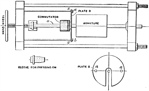
Fig. 731.--Press for forcing on and removing a commutator. Small commutators are pressed on to the shaft by a hand press. All of the larger commutators are pressed on by means of a power press. In the above figure is shown a hand press. The plate B is used in removing old commutators. It is placed back of the commutator as at x y with the slot C over the shaft. Bolts a b are passed through the holes in the plate and secured by nuts. The commutator can then be forced off the shaft. In pressing on a commutator, a sleeve is placed over the shaft at O, and against the commutator. The rear end of the shaft is secured so it will withstand the pressure, and the commutator is forced on. The power presses are built on the principle of a hydraulic press. In pressing on a commutator a piece of babbitt metal or soft brass should be used against the end of the shaft. The shaft should be painted with white lead before having the commutator pressed on, in order to lubricate the shaft so that the commutator will press on easily. The wiper rings are pressed on after the commutator and then the armature is ready to be connected.
Ques. Describe what occurs in starting a motor.
Ans. When the lever of the starting box is moved to the first contact some of the resistance is cut out of the circuit and current flows through the motor. This produces a torque and starts the armature rotating. The movement of the armature induces a reverse voltage, which, as the speed increases, gradually reduces the applied current. With this reduction of current, the torque is reduced and the speed not accelerated as quickly as at first. When the applied current has been reduced to a certain value by the increasing reverse current, the handle of the starting box is moved to the next contact, and so on till all the resistance in the starting box has been cut out, the motor then attaining its normal speed.
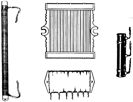
Figs. 732 to 735.--Various starting resistances. The type of resistance used in motor starting rheostats of small size consists usually of tinned iron wire wound on asbestos tubes, as shown in fig. 732, the tubes being firmly supported by porcelain nipples, the ends of which fit into holes in the top and bottom of the enclosing case. In starters of larger size, cast metal grids, as shown in fig. 733, are used. In addition to these types of resistance, some forms of starter are equipped with what is known as "unit" type resistance. In this form, the resistance is built up of a number of separate sections, or units, which are connected to form the complete starting or regulating resistance as the case may be. A single unit consists of a moulded core of vitreous material upon which is wound the resistance wire, as shown in fig. 734. The surface of the unit is then coated with a special cement and baked. By this method the resistance material is protected from mechanical injury and is also made proof against moisture and other conditions which sometimes affect the ordinary type of resistance. In addition to units coated with cement only, there are still other types of units, as in fig. 735, which are provided with a sheet metal covering around the cement, as a further precaution against injury. Each of the various types of resistance described possesses certain characteristics not shared by the others, the use of any particular type being largely governed by conditions of service.
Ques. What is the difference between a starting box and a speed regulator?
Ans. Motor starting rheostats or "starting boxes," are designed to start a motor and bring it gradually from rest to full speed. They are not intended to regulate the speed and must not be used for such purpose.
Failure to observe this caution will result in burning out the resistance which, in a motor starter, is sufficient to carry the current for a limited time only, whereas in the case of speed regulators sufficient resistance is provided to carry the full load current continuously.
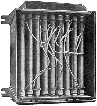
Fig. 736.--View of Cutler-Hammer starter with slate front removed showing open wire coil resistance. The type of resistance here used consists of tinned iron wire wound on asbestos tubes. The bottom of the casing is perforated to secure ventilation.
Ques. For what kinds of service are speed regulators used?
Ans. In cases when the speed must be varied, as in traction motors, organ blowers, machine tool drive, etc.
Ques. How long does it take to start a motor?
Ans. Usually from five to ten seconds.
Ques. How is the starting lever operated?
Ans. It is moved progressively from contact to contact, pausing long enough on each contact for the motor to accelerate its speed before passing to the next.
Ques. What are the conditions at starting in a series motor?
Ans. There is a rush of current, the magnitude of which depends on the amount of resistance cut out at each movement of the starting lever.
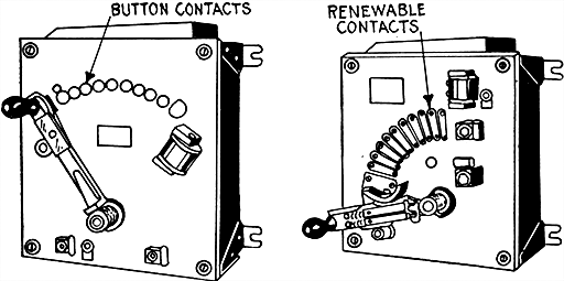
Figs. 737 and 738.--Sliding contact starters. Fig. 737, starter with button contacts; fig. 738, starter with renewable contacts. Motor starters in which the successive steps of resistance are cut out by a pivoted lever carrying a contact shoe which slides over button contacts or over contact segments, are known as sliding contact starters. Button contacts are usually furnished with motor starting rheostats of small size while contact segments are used on those of greater capacity. The contact segment being held in position by two screws, is readily renewable when worn by long service or damaged by arcing. The fixed button contact is not so easily renewed but being used only on small size starters is never likely to be subjected to severe service. Some starters, however, have renewable button contacts.
Ques. How are small series motors started on battery circuits?
Ans. By simply closing a switch to complete the circuit, the resistance of the battery being sufficient to prevent a great rush of current while starting.
Ques. How is a shunt motor started?
Ans. In starting a shunt motor, no trouble is likely to occur in connecting the field coils to the circuit. Since the resistance of the armature is very low, it is necessary on constant voltage circuits to use a starting rheostat in series with the armature.
The necessary connections are shown in fig. 756. The switch is first closed thus sending current through the field coils, before any passes through the armature. The rheostat lever P is then moved to the first contact to allow a moderate amount of current to pass through the armature. The resistance of the rheostat is gradually cut out by further movement of the lever P, thus bringing the motor up to speed.
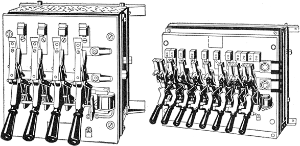
Figs. 739 and 740.--Multiple switch starters. Fig. 739, starter with no voltage release; fig. 740, starter with no voltage release and circuit breaker. The multiple switch type of starter is designed to overcome the arcing on sliding contacts which, in the case of large motors would be very severe. The cutting out of each step of resistance is accomplished in the multiple switch starter by a separate carbon contact switch which breaks the circuit with a quick snappy action.
Ques. How does the reverse voltage affect the starting of a motor?
Ans. When a motor is standing still, there is no reverse voltage, and the current taken at first is governed principally by the resistance of the circuit. If the motor be series wound, there is a momentary reverse voltage, due to self-induction while the field is building up. If the motor be shunt wound, self-induction delays the current through the field coils, but that through the armature is not impeded by such cause. When the armature begins to revolve, reverse voltage is developed which increases with the speed. The resistance of the starting box may be gradually cut out as the armature comes to speed. Thus the reverse voltage gradually replaces ohmic drop in limiting the current as the motor comes to speed.
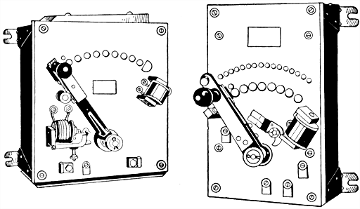
Fig. 741.--Starting rheostat with no voltage and overload release. The no voltage release permits the starting lever to fly to the "off position" should the voltage fail momentarily, thus protecting the motor against damage should the voltage suddenly return to the line. The movement of the lever is due to a spring. The overload device causes the lever to back to the off position should the current exceed a predetermined maximum for which the release is adjusted.
Fig. 742.--Compound starter. Rheostats designed for the double duty of starting a motor and regulating its speed are commonly known as compound starters, the resistance provided being a combination of armature resistance for starting duty and shunt field resistance for speed regulation.
Failure to Start.--This fault, which is liable to occur in a motor of any description, is similar to failure to excite in a dynamo, and is liable to be produced by any of the causes mentioned in connection with the latter fault, excluding insufficient speed, and insufficient residual magnetism.
When a motor fails to start, it should first be ascertained if a supply of electrical energy be available in the mains. This may readily be discovered by means of a voltmeter, or if low tension service, by means of the fingers bridging across the main terminals. If the supply of energy be present, the contact arm of the starter should be moved into such position that all resistance is inserted into circuit with the motor. This is important, as the motor may start suddenly while trying to ascertain the cause of the stoppage.
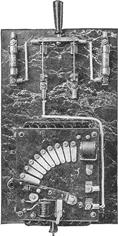
Fig. 743.--Starting panel. In installing any kind of motor starting rheostat, it is necessary to provide main line knife switch and fuses in addition to the starting box. The appearance of the installation can be much improved by mounting all of these upon one panel.
Having closed the switch, if the motor fail to start, it will be advisable to remove the load if possible, as the failure may arise from an overload of the machine. This being effected and the motor not starting, the terminals of the latter should be tested by the means already described for voltage. If no voltage be generated, a broken circuit or a defective contact may be looked for in the main fuse, switch, or starting box. The resistance coils of the latter, through the heat developed, frequently break in positions out of sight. If a defective contact of this nature cannot readily be seen, the contact arm should be moved slowly over the contacts, as it is possible the broken coil may be cut out of circuit by this means.
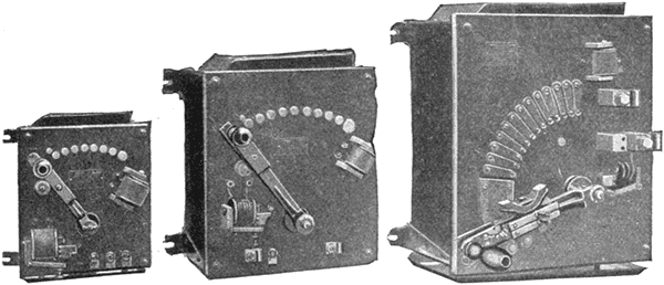
Figs. 744 to 746.--Cutler-Hammer motor starting rheostats with no voltage and overload release. Fig. 744, starter with fixed button contact, fig. 745, with renewable button contact, and fig. 746, with contact segments. In construction the resistance is enclosed in a pressed steel box on which is mounted a marbleized slate panel carrying the starting lever, contacts and protective devices. By means of a calibrated scale, the overload release (shown in the lower left hand corner, figs. 744 and 745, and in the lower right hand corner fig. 746) can be set to break the circuit on any overload not exceeding 50 per cent. of the rated capacity of the motor. This calibrated scale can also be used for determining, with a fair degree of accuracy, the amount of current being consumed by the motor.
If a difference of pressure exist between the motor terminals, the field magnets will, if shunt or compound wound and in good order, be excited, which may be ascertained by means of a bar of iron. If no magnetism be present, it will of course, indicate a broken or bad connection, either between the terminals of the field coils, or one or more of the coils themselves. If the bar pull strongly, the position of the brushes upon the commutator in regard to the neutral points should be ascertained, and the rocker adjusted, if necessary, to bring them into their correct positions. If this fail to start the motor, the connecting leads from the motor terminals to the brushes and the brushes themselves should be carefully examined for broken or bad connections, and defective contact of the brushes with the commutator. In the latter case, it may arise from a dirty state of the commutator, or from the brushes not being fed properly. If due to these causes, pressing the brushes down upon the commutator with the fingers will probably start the motor. If the failure to start arise from none of these causes, it is probably due to the field coils acting in opposition, or to a short circuited armature. This latter remark applies more especially to motors provided with drum armatures.
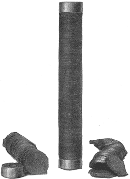
Fig. 747.--Allen-Bradley compression type resistance units. The contact resistance between the discs composing the resistance column is subject to variations of pressure thereby producing proportionate resistance changes in the column as a whole. In the complete resistance unit, the resistances column is encased in a drawn steel tube, which is lined with a highly refractory cement, for purpose of insulation, affording the column both mechanical and electrical protection and excluding the air which effectually prevents any combustion should the column become red hot due to overload. The ends of the tube are closed by means of caps through which pass electrodes for making connections between the discs and exterior conductors. The steel tube, when necessary, is provided with ribs or fins for the dissipation of acquired heat.
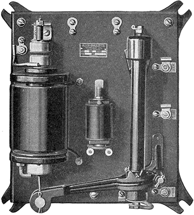
Fig. 748.--Allen-Bradley type Z automatic motor starter. The operation of this machine is as follows: When the main switch is closed, the motor circuit is made through the fuses, resistance unit, current relay, and the motor armature. At the same time, the solenoid circuit is closed (this is connected directly across the line, and takes a current which is a small fraction of an ampere), and the plunger of the solenoid is drawn up, which produces a pressure on the resistance unit, and increases the current in the motor circuit to the predetermined value at which the current relay is set. When this value is reached the current relay operates and opens the solenoid circuit, which reduces the magnetic pull and allows the solenoid plunger to drop back slightly. This action increases the resistance in the motor circuit, which decreases the current sufficiently to allow the relay to close again. Similar cycles of operation are repeated as the motor accelerates, and each time the plunger is drawn a little farther into the solenoid, until the short circuiting contacts on the top are pushed together, which short circuits the current relay and resistance unit, making them inoperative, and completing the operation of starting the motor. It will be noted that in starting a motor with this device the current is always held down to a certain predetermined value, and it is impossible to overload the motor by too rapid starting. The current relay is calibrated in amperes, and may be set to suit existing conditions. The action of the starter being controlled by a current relay and not by an oil or air dash pot, the motor will start rapidly when under a light load, and slowly when more heavily loaded. The fuses or circuit breakers may be set at a value that will furnish protection to the motor under running conditions.
Precautions with Shunt Motors.--With motors of this type, because of the large amount of self-induction in the shunt windings, it is important to note: 1, that in switching on the field magnet, the current may take an appreciable time to grow to its normal value, and 2, that in switching off, especially with quick break switches, high voltages are induced in the windings, which may break down the insulation.
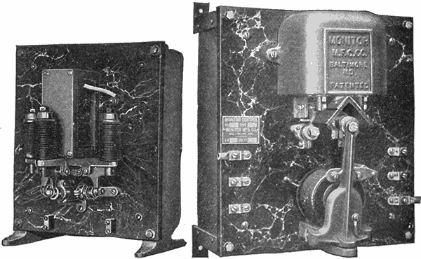
Fig. 749.--Monitor starter giving automatic start with knife switch control; designed for use with printing presses. It consists of a set of solenoids connected in series and so interoperating as to cut resistance out of the armature circuit of the motor as the apparatus it is driving comes up to speed. This type is for small motors or where no need arises for speed regulation; there is, therefore, no adjustment of speed possible aside from an actual change in motor conditions. At full speed the motor is directly across the main supply line.
Fig. 750.--Monitor automatic starter, equipped with relay for push button control.
Ques. What provision is made so that the magnetizing current will have time to reach its normal value?
Ans. The field connections are generally separated from the actual starter, and taken to the main switch, so that wherever the main switch is closed, the current flows through the field coils, before the starting lever is moved.
Ques. How are the connections arranged to avoid excessive voltage in the windings due to self-induction?
Ans. Generally the armature and field magnet circuits are placed in a closed circuit that is never opened.
In other cases, in order that the rise of voltage may not injure the insulation when the shunt is opened, a special form of main switch is sometimes used which, before breaking from the supply, puts a non-inductive resistance across the shunt of the motor. This is known as a flashing resistance.
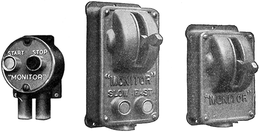
Figs. 751 to 753.--Monitor control switches. Fig. 751, push button "start" and "stop" switch; fig. 752, safety lever control switch with "slow" and "fast" buttons for rotary printing presses. This device will upon pressure of the "start" button, set the machine in motion and bring it up to the predetermined speed, either as previously set by the starter limits or by the setting of the rheostat arm. The stop button projects some distance beyond any other portion of the device, in order that in case of emergency the operator may stop the machine merely by hitting the face of the switch with his open hand. The lever control switch, fig. 753, is similar in its action to the push button switch but combines two other features: locking point, and visual indication of the station from whence the press has been stopped. With the lever at the downward position, the press is locked and cannot be started from any other station. In order to make the press ready to start the lever must be raised to the central position. Thus a man may safely enter the press without delay by setting his station to the locked position, knowing that it cannot be started except by some one coming to that station and realizing that the press has been purposely locked. Also, by looking along the press, it is possible to tell from which station it has been locked, and proper action can be immediately taken. The safety control station is usually combined for use on large rotary presses with the "slow" and "fast" push buttons as shown in fig. 752. A pressure upon the fast or slow buttons will cause the press speed to be correspondingly accelerated or retarded, and this action will continue so long as the button is pressed. The press continues to run at the speed attained at the instant of releasing the button. Any speed may, therefore, be selected or changed to suit momentary requirements. This gives complete control excepting reversal which is not required of such a press.
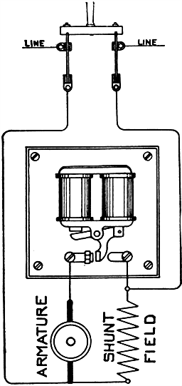
Fig. 754.--Wiring diagram of the standard form of Monitor controller. A set of solenoids are connected in series and so interoperating as to cut resistance out of the armature circuit of the motor as the apparatus it is driving comes up to speed. The controller is designed to be used on all classes of work. In its simplest form, a single copper and graphite contact, is controlled by two magnets, so proportioned as to cut out the entire starting resistance when the armature current falls to a predetermined value. In the larger sizes, the number of steps controlling the resistance is increased and arranged to produce the correct acceleration. In every case the regulation of the starting resistance is effected entirely by the current passing to the motor without the use of dash pot, mechanical governor or delicate cut outs. The time element is thus directly proportioned to the load and the motor brought up to speed in the shortest time consistent with the load, but always with safe limitation of the armature current. The distinction between the current controlled starter and the starter with dash pot governor should be noted. The starter here shown limits the starting current to a fixed value throughout the starting operation, which is an ideal condition and prevents blowing fuses in starting.
Ques. How can shunt motors be controlled from a distant point?
Ans. The starter and switch are placed at the desired point and the two main wires and the field wires run from that point to the motor.
This requires additional wire which increases the cost and line loss.
Regulation of Motor Speed.--Motors are generally run on constant voltage circuits. Under these conditions, the speed of series motors varies with the load and at light loads becomes excessive. Shunt motors run at nearly constant speeds.
For many purposes, particularly for traction, and for driving tools, it is desirable to have speed regulation, so that motors running on constant voltage circuits may be made to run at different speeds.
The following two methods are generally used for regulating the speed of motors operated on constant voltage circuits:
1. By inserting resistance in the armature circuit of a shunt wound motor;
2. By varying the field strength of series motors by switching sections of the field coils in or out of circuit.
Ques. Describe the first method.
Ans. This method is illustrated in fig. 756. When the main switch is closed, the field becomes excited, then by moving the lever P of the starting rheostat the various contacts (1, 2, 3, 4, 5), more or less of the rheostat resistance is cut out of the armature circuit, thus varying the speed correspondingly.
This is the same as the method of starting a motor, that is, by variation of resistance in armature circuit, but it should be noted that when this method is used for speed regulation, a speed regulating rheostat should be used instead of the ordinary starting box, because the latter, not being designed for the purpose, will overheat and probably burn out.
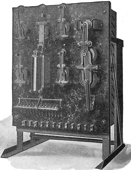
Fig. 755.--Monitor printing press controller. It provides variable speed and other control features required in the operation of large rotary presses, such as those used for printing newspapers. From any one of various stations similar to the one illustrated in fig. 753, located at all desirable places about the press, the latter may be started, stopped, accelerated, slowed down or locked. It differs from other types of printing press controller in that the solenoid has an overall maximum pull of less than one inch and does not actuate the main line current directly but through pilot circuits, which in turn, operate flapper switches; there are no sliding contacts. At the control stations, the operator can distinguish the accelerating button from the retarding button by the sense of touch and obviously he can in the same manner ascertain the position of the lever. The position of the lever whether at start, stop or safety, can be readily observed at a distance. When the lever of either control station is placed at stop, the current is disconnected from the motor and a powerful dynamic brake brings the press to rest without delay and without shock or harmful strain. The start will always be made with all resistance in the armature circuit, and with full field, and should the current supply fail, the controller will release and open the circuit to the motor. This controller will give a speed range as low as 10% of normal speed by armature resistance and, by field control, any increase within the speed of the motor.
Ques. Describe the second method.
Ans. This method of regulating the speed of a series motor is shown in fig. 757. The current through the armature will flow through all the field windings when the position of the switch lever S, is on contact 4, and the strength of the field will be the maximum. By moving the arm to contact 3, 2, etc., sections of the field winding are cut out, thus reducing the strength of field and varying the speed.
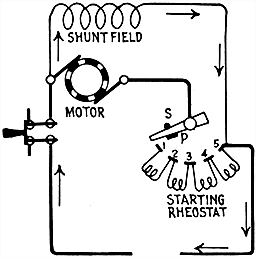
Fig. 756.--Speed regulation of shunt motor by variable resistance in the armature circuit.
Ques. How does the speed vary with respect to variation of field strength?
Ans. Decreasing the field strength of a motor increases its speed, while increasing the field strength decreases the speed.
Under the conditions of maximum field strength, as with switch S on point 1, the torque will be greatest for any given current strength and the reverse voltage also greatest at any given speed. The current through the armature of the motor, to perform any given work, will thus be a minimum, as well as the speed at which the motor has to run, in order to develop sufficient reverse voltage to permit this current to flow. Regulation of speed by varying the field strength is limited in range of action, since the field saturation point is soon reached, moreover, with too low a field strength, armature reaction produces excessive field distortion, sparking, etc.
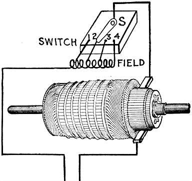
Fig. 757.--Speed regulation of series motor by cutting out sections of the field winding. In this method the field winding is tapped at several points, dividing the coil into sections and the leads from these points are connected a multi-point switch of the type that would be used on a rheostat. By moving the lever S, to the left or right, the current will flow through one or more sections of the field winding, thus decreasing or increasing the ampere turns and thereby providing means of regulation.
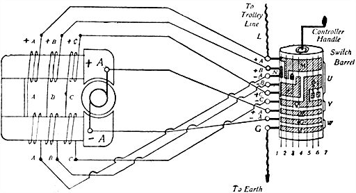
Fig. 758.--Speed regulation of a series motor by the method of short circuiting sections of the field winding. It will be seen that there are seven different positions for the contact springs on the barrel contacts. A. represents the armature and brushes, little A, B, and C, the divided field magnet coils, L the line connection, and G the earth connection. The diagram shows the connections for trolley car operation.
Ques. How is the speed of shunt and compound motors varied with respect to the normal speed in the two methods?
Ans. The first method (variable resistance in armature circuit) reduces the speed below the normal or rated speed of the machine, while the second method increases the speed above the normal.
In the first method the amount of speed reduction depends partly upon the amount of resistance introduced into the armature circuit, and partly upon the load.
In the second method the amount of speed increase depends entirely upon the amount of resistance placed in the shunt winding circuit.
Eighty-five per cent. is about the maximum speed reduction obtainable by armature resistance but so great a reduction is seldom satisfactory since comparatively slight increases in the load will cause the motor to stall.
Shunt field regulation may be obtained up to any point for which the motor is suited, the only limitation in this case being the maximum speed at which the motor may be safely operated.
It should be remembered, however, that speed increase by shunt field weakening increases the current in proportion to the increase in speed, and care should be taken not to overload the armature.
NOTE.--A compound motor may be made to run at constant speed, if the current in the series winding of the field be arranged to act in opposition to that of the shunt winding. In such case, an increase of load will weaken the fields and allow more current to flow through the armature without decreasing the speed of the armature, as would be necessary in a shunt motor. Such motors, however, are not very often used, since an overload would weaken the fields too much and cause trouble. If the current in the series field act in the same direction as that in the shunt fields, the motor will slow up some when a heavy load comes on, but will take care of the load without much trouble.
NOTE.--Motors have much the same faults as dynamos, but they make themselves manifest in a different way. An open field circuit will prevent the motor starting, and will cause the melting of fuses or burning out of the armature. A short circuit in the fields, if it cut out only a part of the winding, will cause the motor to run faster and very likely spark badly. If the brushes be not set exactly opposite each other, there will also be bad sparking. If they be not at the neutral point, the motor will spark badly. Brushes should always be set at the point of least sparking. If it become necessary to open the field circuit, it should be done slowly, letting the arc gradually die out. A quick break of a circuit in connection with any dynamo, or motor is not advisable, as it is very likely to break down the insulation of the machine. The ordinary starting box for motors is wound with comparatively fine wire and will get very hot if left in circuit long. The movement of the arm from the first to the last point should not occupy more than thirty seconds and if the armature do not begin to move at the first point, the arm should be thrown back and the trouble located.
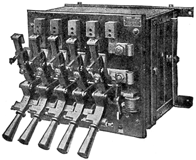
Fig. 759.--Cutler-Hammer multiple switch starter with no voltage release; for use with large motors, or with motors of medium size where the starting conditions are severe or when more than fifteen seconds are required to accelerate the motor. In operation, the cutting out of each step of resistance is accomplished by a separate lever and the levers themselves are so interlocked as to prevent closing switches except in proper order, beginning with the lever on the left. The last switch (the one on right hand side) is held by an electro-magnet when closed, each of the other switches being held in the closed position by a latching device on the switch next to it. In front of each switch is placed a metal stop, so arranged as to prevent any switch being operated until the one next to it on the left has been closed. These metal stops constitute the interlocking mechanism and prevent the starting of the motor in any way except by closing the switches in regular rotation, thus insuring proper resistance in the circuit and protecting the motor from excessive starting currents. When the current is interrupted, the electro-magnet releases the last switch, which, on opening, releases the latch on the switch next to it, allowing that switch to open, and this in turn releases the next latch and so on, the switches opening automatically one after another. In starting the motor, each switch should be closed quickly and firmly, pausing a second or two before closing the next switch to give the motor time to accelerate.
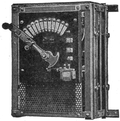
Fig. 760.--Cutler-Hammer speed regulator with no voltage release, regulation by armature resistance only, reducing speed of motor below normal. No resistance in the armature circuit. No provision is made in regulators of this type for increasing the speed of the motor. The maximum speed obtainable when these regulators are used is, therefore, the normal speed at which the motor is designed to operate with no resistance in circuit. With all resistance in circuit and the motor taking normal current these regulators will reduce the speed of the motor 50 per cent. If the motor be taking less than normal current the percentage of speed reduction obtainable will be correspondingly less. The notched fan tail extension on the lower end of the lever engages with a magnetically operated pawl to hold the lever squarely on any contact so long as the no voltage release magnet is energized.
Ques. How is a wide range of speed regulation secured?
Ans. By a combination of the two methods.
Regulation by Armature Resistance.--Speed regulators for this method of regulation, are designed to carry the normal current on any contact without overheating and when all the resistance is in the circuit, they will reduce the speed of the motor about 50 per cent. provided the motor be taking the normal current. When operating without resistance in the armature circuit, shunt wound and compound wound motors will regulate to approximately constant speed regardless of load. This characteristic of inherent regulation is lost, however, when armature resistance is employed to reduce the speed of the motor, fluctuations in load resulting in fluctuations in speed, which become more noticeable as the amount of resistance inserted in the armature circuit is increased. Accordingly, it becomes necessary to move the lever of the speed regulator forward or backward to again obtain the speed at which the machine was operating before the load changed.
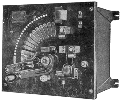
Fig. 761.--Cutler-Hammer compound starter with no voltage and overload release. This is a starting rheostat and field regulator combined. In operation, two levers are employed, both being mounted on the same hub post and one lying directly under the other. The upper lever only is provided with a handle, but when moving from the off position to the starting position (that is to say, from left to right) the lower, or starting, lever is carried along by the upper, or speed regulating, lever until it comes in contact with the no voltage release magnet where it is held fast by the attraction of the magnet, leaving the upper lever free to be moved backward over the field contacts, thus weakening the shunt field of the motor little by little until the desired speed is attained. During the operation of starting the motor, the field resistance is short circuited by an auxiliary contact (the slotted metal strip shown near center of rheostat) but as soon as the starting lever touches the no voltage release magnet or, in other words, when the motor has been accelerated to normal speed, this short circuit is removed, and the field resistance becomes effective for speed regulation. The motor is accelerated from rest to normal speed by moving both levers from left to right, while increases in speed above normal are obtained by moving the upper lever from right to left. Only the lower, or starting lever comes into contact with the no voltage release magnet. This lever is provided with a strong spiral spring which tends always to throw the lever back to the off position. Hence should the voltage fail, the no voltage release magnet releases the starting lever and this, in flying back to the off position, opens the armature circuit of the motor and carries the speed regulating lever with it to the off position. The upper, or speed regulating lever, not being influenced by the spring, though mounted on the same hub post as the starting lever, may be moved back and forth at will or left indefinitely in the position which gives the speed desired.
When the speed of a motor driving a constant torque machine is reduced by inserting resistance in the armature circuit there is no corresponding reduction in current consumed. The motor runs more slowly simply because a part of the energy impelling it is shunted into the resistance and there dissipated in the form of heat. Hence, whether the motor be operating at full speed or half speed, the amount of current consumed is the same; the only difference being that in the one case all the energy taken from the line is expended in driving the motor while in the other case only one half is utilized for power, the other half being dissipated in the resistance. Speed regulation by armature resistance only is therefore open to two objections: 1, the difficulty of maintaining constant speed under varying load conditions, and 2, the necessity of wasting energy to secure speed reduction. These objections are, in part, offset by the fact that speed reduction by armature resistance may be applied to any motor of standard design and requires nothing more than the simplest and least expensive speed regulating rheostat.
In cases where the motor will be operated nearly always at full speed, the difference in first cost of the installation may justify the use of the armature resistance method of control. As a rule, speed regulation by shunt field resistance is preferable.
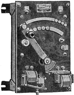
Fig. 762.--Cutler-Hammer compound speed regulator with no voltage and overload release; regulation by combined armature and shunt field resistance, designed to both decrease and increase the speed of a motor. Speed reduction is accomplished by inserting resistance in the armature circuit, the maximum amount of speed reduction obtainable with these controllers being 50 per cent. below normal. Speed increase is obtained by inserting resistance in the shunt field circuit, the maximum amount of speed increase obtainable with these controllers being 25 per cent. above normal.
Regulation by Shunt Field Resistance.--Since regulation by this method is for speeds above normal, a starter must be used to bring the motor up to its rated speed. Usually the starter is combined with the regulator, as shown in fig. 761, the device being called a compound starter.
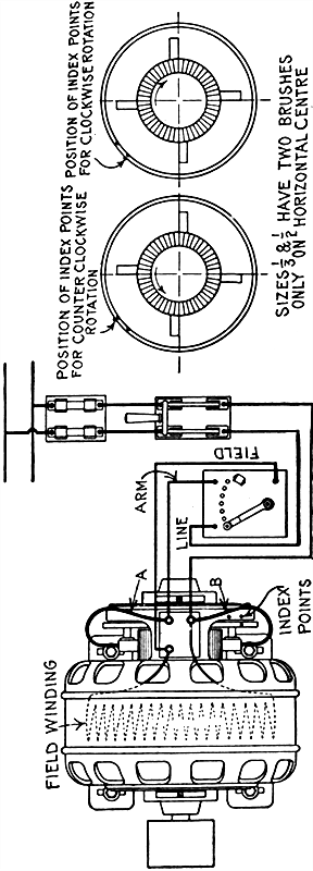
Figs. 763 to 765.--Holzer-Cabot shunt wound motor; diagrams showing connections and positions of index point for forward and reverse rotation.
LOCATION AND SETTING.--The motor should be placed in as cool, clean and well ventilated a location as possible, away from acid or other fumes which would attack the metal parts or insulation, and should be easily accessible for cleaning and oiling. Do not put it in some corner where care of motor will be neglected because of the trouble of getting at it. The motor should be set so that the shaft is level and parallel with the shaft it is to drive so that the belt will run in the middle of the pulleys. Do not use a belt which is much too heavy or too light for the work it has to do, as it will materially reduce the output of the motor. The belt should be about one-half inch narrower than the pulley.
ROTATION.--In order to reverse the direction of rotation, interchange leads A and B, and shift brush ring as shown in the diagram above.
SUSPENDED MOTORS.--Motors with ring oil bearings may be used on the wall or ceiling by taking off end caps and revolving 90 or 180 degrees until the oil wells come directly below the bearings.
STARTING.--Before starting the motor see that the armature revolves freely, that the bearings are full of oil, and the oil rings are in place and free to turn.
Examine connections carefully to see that they are according to above diagram, after which proceed as follows:
1. Close the main knife switch. This action should not allow any current to pass through the motor (see Note 2);
2. Move the lever of the starting rheostat quickly and squarely onto the first segment, and hold it there for about a second;
3. Move the lever to the second segment and hold it there for about a second;
4. Move the lever to the third segment and hold it there for about a second, and so on from one segment to the next until the lever has been moved over all the segments to the short circuit position, where it should be held firmly by the retaining magnet.
If the motor do not start when the lever of the starting rheostat is on the third segment, open the main knife switch and look for the trouble. This may consist of any of the following:
a. Wrong connections;
b. Too great a load on the motor;
c. The motor brushes not in proper position;
d. An open circuit of some kind;
e. A short circuit of some kind.
NOTE 1.--It is always advisable, in case of trouble, to make sure that the fields of the motor are magnetized. This test is easily made by first closing the main knife switch, then moving the lever of the starting rheostat to the first segment, and finally having an assistant place a screw driver or other piece of iron against the pole pieces of the motor. If the fields be magnetized, a heavy pull on the iron should result.
NOTE 2.--Any possibility of arcing on the first contact of the starting rheostat when starting can be obviated by first moving the lever onto the initial contact, holding it there, and then closing the main line switch, after which proceed as per paragraphs 3 and 4.
TO STOP THE MOTOR.--Open the main knife switch and let the starting rheostat take care of itself. The lever will not fly back immediately, but will hold until the motor has slowed down considerably.
NOTE.--The above directions apply only to starters of the sliding contact type.
TEMPERATURES.--If located as instructed above, these motors will carry full load as indicated on the name plate on the motor with a temperature rise of not over 40 degrees Centigrade, or 75 degrees Fahrenheit above the surrounding air. This will feel hot to the hand but is far below the danger point. If the motor feel too hot, get a thermometer and measure the temperature. To do this, place the bulb of the thermometer for 10 minutes against the frame, cover with a cloth or piece of waste, and note temperature as compared with that of room. If the motor run in a small, enclosed space with no ventilation, the temperatures will be somewhat higher than those given above.
OILING.--Fill the oil wells to the overflow before starting and keep them full. Use good "dynamo oil." Be sure that the oil rings turn freely while the motor is running. If in a dirty place, draw off the old fluid and fill with new every two or three months.
CARE OF MOTOR.--The motor must be kept clean. If the commutator become rough, smooth it up with No. 00 sandpaper moistened with oil. When fitting new brushes or changing them, always sandpaper them down until they fit the commutator perfectly, by passing to and fro beneath the brush a strip of sandpaper, having the rough side toward the brush.
Brushes must always be renewed before the metal of the holder comes in contact with the commutator.
Don't use anything on commutator except good mineral machine oil, or kerosene, and this only in very small quantities applied with a cloth having no lint or threads.
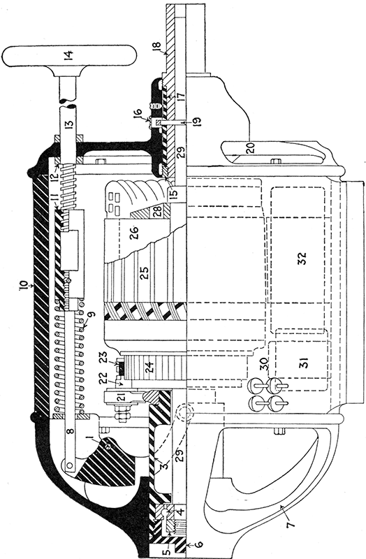
Fig. 766.--Sectional view showing principal parts of Reliance adjustable speed motor: 1, lever fulcrum pin; 2, lever; 3, sliding thrust bearing box; 4, ball bearing; 5, armature shaft end nut; 6, cap; 7, commutator end yoke; 8, lever rod; 9, compression spring; 10, steel frame; 11, speed adjustment nut; 12, thrust collars and pins; 13, hand wheel rod; 14, hand wheel; 15, sleeve nut; 16, oil well cover; 17, bearing bushing; 18, sleeve; 19, oil ring; 20, pinion end yoke; 21, rocker arm; 22, brush holder stud; 23, brush; 24, commutator; 25, armature; 26, armature laminations; 27, armature coils; 28, armature end plate; 29, armature shaft; 30, leads; 31, axial position of commutating pole; 32, axial position of main field pole; 33, slide rail screws; 34, end yoke cap screws; 35, slide rails; 36, commutating coil; 37, commutating pole; 38, main field pole; 39, main field coil.
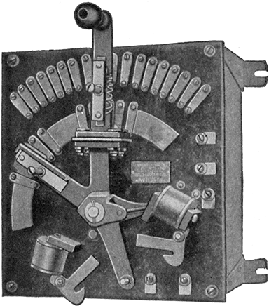
Fig. 767.--Cutler-Hammer reversible starter with no voltage release, adapted to start and operate motor at full speed in either direction, such for instance as motors driving auxiliary motions on lathes, planers and other machine tools which may rotate in either direction but always at constant speed. They are not designed to reduce the speed of the motor, but merely to start it and bring it smoothly up to full speed in either direction. Two no voltage release latching devices are provided so that the lever will be held in the full speed position in either direction so long as the voltage of the line remains constant. On failure of voltage a strong centering spring attached to the hub-post of the lever throws the latter to the central, or off position. The shunt field circuit is not opened by starters of this type.
The weakening of the shunt field of a motor by the insertion of resistance in the shunt field circuit causes the armature to revolve more rapidly. One advantage of this method of control is that the motor will inherently regulate to approximately constant speed under widely varying load conditions. Another advantage is found in the fact that all of the current taken from the line is utilized for power, the changes in speed being obtained not by dissipating a portion of the effective energy in the resistance (as in the case of the armature resistance method of control) but by weakening the reverse voltage by inserting resistance in the shunt field circuit. Speed increase by shunt field weakening is limited, however, to about 10 to 15 per cent. above the normal speed in motors of standard construction. Greater ranges of speed can be obtained from motors especially designed for shunt field control but should not be attempted with motors of standard design without first ascertaining from the manufacturer the maximum safe speed.
Combined Armature and Shunt Field Control.--Regulation by combined armature and shunt field resistance is by far the easiest way of obtaining a wide range of speeds. Rheostats embodying these methods are known as compound speed regulators, one form being shown in fig. 762. Standard regulators can be obtained giving a wide range of speed variation, and special regulators may be constructed giving practically any desired range.
Selection of Starters and Regulators.--Unsatisfactory operation of these devices is, in nearly all cases, due to lack of precaution in selecting the proper piece of apparatus for the work to be done. One of the commonest errors is to select a rheostat of insufficient capacity. If the current required to operate the motor at full speed with no resistance in circuit be greater than the rated capacity of the rheostat, overheating of the resistance will result. An increase in temperature even to a point where the hand cannot be held on the enclosing case need cause no apprehension, but should the resistance become red hot it indicates that the apparatus is being worked far beyond its capacity, and the load on the motor should be reduced or a regulator of greater capacity substituted.
If the current required to operate the motor at full speed with no resistance in circuit be less than the rated capacity of the rheostat no overheating will occur, but it will not be possible to secure the full 50 per cent. speed reduction the rheostat is designed to give with all resistance in circuit.
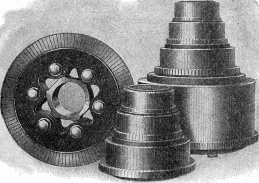
Fig. 768.--Various sizes of Watson commutator. The segments are punched from hard drawn copper strip and are insulated from each other and the core by amber mica, of hardness corresponding to that of the copper in order that the wear of mica and copper may be uniform. The segments are assembled in a ring under great pressure and are repeatedly heated and tightened, being finally secured and rigidly locked together.
In ordering a starter or regulator, the manufacturer should be furnished with the following information:
Horse power of motor with which speed regulator will be used;
Voltage of motor;
Winding of motor, whether series, shunt, or compound wound;
Nature of the machine which motor is to operate;
Normal rated speed of motor to be used;
Maximum speed at which it is desired to operate the motor;
Minimum speed at which it is desired to operate the motor;
Whether controller will ever be required to reverse direction of motor or to operate it in one direction only;
If reversible controller be desired, whether or not full range of speed control is required in both directions;
Whether the regulator shall be equipped with any of the following devices: no voltage release, overload release, knife switch, fuses;
Whether button contacts or renewable contact segments are preferred;
Giving, also, if possible, the resistance of the shunt field cold, and the shunt field current at the maximum speed required. If this cannot be ascertained, give horse power, voltage, normal speed, maximum speed required, serial number of motor and name of manufacturer.
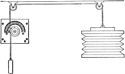
Fig. 769.--Organ blower speed regulator; diagram showing operation and method of installing. A cord running from the top of the organ bellows passes over two pulleys and is then made fast to the chain furnished with the regulator. This chain passes around a sheave which turns on a post projecting from the center of the slate panel. Attached to the lower end of the chain is a weight, also furnished with the regulator. As the air is exhausted from the bellows the latter slowly collapses, drawing the rope down with it, and in so doing turns the sheave from left to right, thus cutting resistance out of circuit and increasing the speed of the motor which pumps air into the bellows. Responding to the inrush of air, the bellows expands, relaxing the tension on the rope which is now pulled in the opposite direction by the weight, thus turning the sheave from right to left, cutting resistance into circuit once more and slowing down the motor. The speed of the motor is thus automatically regulated by the bellows, with the result that a practically uniform pressure is maintained at all times. In connection with an organ blower regulator it is necessary to install a separate starting rheostat. This is required for the reason that all organ bellows leak. During the intermissions in the musical part of the service, or at other times when the blower is not operating, the air gradually escapes and the bellows settles down, moving the rheostat arm to the right and cutting out resistance. With the motor at rest and the bellows empty all the blower regulator resistance would be short circuited and it is therefore necessary to avoid throwing the motor directly across the line when starting again. A starting rheostat with no voltage release is suitable for this purpose, and should be installed within easy reach of the organist, so that a moment or two before beginning to play he can move the lever of the starting box and get the motor into operation. Where remote control is desirable a self starter can be substituted for the manually operated starting box, in which case the entire installation can be controlled by a push button, or single throw knife switch.
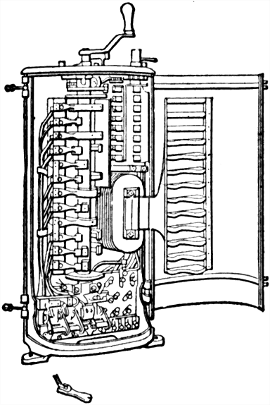
Fig. 770.--General Electric type K7 controller with cover open showing construction. The mechanism consists of a long spindle, carrying a number of heavy brass or gun metal segments, making contact for a longer or shorter time with a corresponding number of spring contacts. The spindle is provided at its upper end with a handle, and the various contacts are made by turning it through an arc of about 150°. For this method a moderate amount of resistance is employed. The first contact joins both motors and the full amount of resistance in series across the line, and as the motors are standing still, maximum current flows so that they exert their full torque. The moment they start to revolve, the current tends to fall, due to the generation of a reverse voltage; to prevent this and maintain a heavy current for some time, thus obtaining rapid acceleration, the resistance is arranged so that it can be gradually reduced, until at about the fourth notch the two motors are in series without resistance across the line. To increase still further the speed in the above type of controller, the series fields may be shunted, and then the next steps place the motors in parallel with the resistance.
Speed Regulation of Traction Motors.--The speed regulator for motors of this class is called a controller, and being located in an exposed place is enclosed in a metal casing. Controllers are designed to be used for starting, stopping, reversing, and regulating the speed of motors where one or more of these operations have to be frequently repeated.
The controller used with a single motor equipment is practically the same as any other single motor starting box, excepting that the resistance has sufficient carrying capacity to be left in the circuit some time. When the motor is to operate at full speed all the resistance is cut out. To reverse, a reversing notch is placed in the armature or field circuit, but not in both.
Ques. What provision is made to overcome the arc when the circuit is opened?
Ans. A magnetic field is used with such polarity that it blows out the arc.
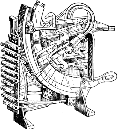
Fig. 771.--Controller of the Rauch and Lang electric vehicles. It is of the flat radial type. Two movable copper leaf contacts of ample size make all commutations necessary to obtain the various speeds. Five speeds forward and reverse are provided.
Magnetic blow out coils are used on all controllers designed for 500 volt circuits, and on types designed for lower voltages requiring more than 60 amperes normal capacity.
The coils are wound with either copper wire or flat strips of sufficient capacity to carry full load current continuously without undue heating, and after being wound they are treated with an insulating compound making them moisture proof.
Ques. What provision is made to prevent reversal before bringing the controller lever to the "off" position?
Ans. Controllers having separate reversing cylinders are fitted with mechanical interlocks making it necessary to place lever in off position before reversing.
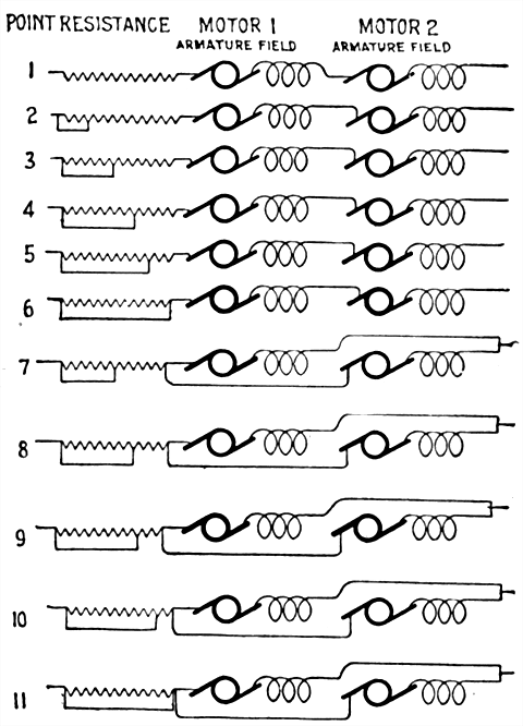
Figs. 772 to 782.--Diagram of controller connections, illustrating the series parallel method of two motor control.
Two Motor Regulation.--With a two motor equipment, the controller becomes more complicated because it must be arranged to switch the motors in series or in parallel, so as to secure economy at half and full speed. The various connections of series-parallel regulation are shown in figs. 772 to 782.
From these diagrams it is seen that the motors are first operated in series until all the resistance is cut out by the controller (figs. 772 to 777).
The next point on the controller puts the two motors in parallel with some resistance in the circuit (fig. 778), which resistance is gradually short circuited on the remaining controller points, until at full speed all the resistance is cut out, the two motors remaining in parallel (figs. 778 to 782).
Stopping a Motor.--If it be desired to stop a motor, the main switch is opened. As the armature of the motor continues to operate, due to its inertia, it generates an electromotive force which sends a current through the shunt connected field circuit and helps to maintain the field excitation. When the speed of the motor has decreased sufficiently so as not to endanger the motor should the main switch be thrown, the current in the series magnet becomes weakened, and the spring throws back the starting box arm.
It should be noted that in stopping a motor having a starting box provided with a no voltage release simply open the main switch and do not touch the lever because otherwise, the self induced voltage of the field circuit may puncture the field winding or the insulation of the adjoining wires in the starting box.
HAWKINS PRACTICAL LIBRARY OF ELECTRICITY IN HANDY POCKET FORM PRICE $1 EACH
They are not only the best, but the cheapest work published on Electricity. Each number being complete in itself. Separate numbers sent postpaid to any address on receipt of price. They are guaranteed in every way or your money will be returned. Complete catalog of series will be mailed free on request.
ELECTRICAL GUIDE, NO. 1
Containing the principles of Elementary Electricity, Magnetism, Induction, Experiments, Dynamos, Electric Machinery.
ELECTRICAL GUIDE, NO. 2
The construction of Dynamos, Motors, Armatures, Armature Windings, Installing of Dynamos.
ELECTRICAL GUIDE, NO. 3
Electrical Instruments, Testing, Practical Management of Dynamos and Motors.
ELECTRICAL GUIDE, NO. 4
Distribution Systems, Wiring, Wiring Diagrams, Sign Flashers, Storage Batteries.
ELECTRICAL GUIDE, NO. 5
Principles of Alternating Currents and Alternators.
ELECTRICAL GUIDE, NO. 6
Alternating Current Motors, Transformers, Converters, Rectifiers.
ELECTRICAL GUIDE, NO. 7
Alternating Current Systems, Circuit Breakers, Measuring Instruments.
ELECTRICAL GUIDE, NO. 8
Alternating Current Switch Boards, Wiring, Power Stations, Installation and Operation.
ELECTRICAL GUIDE, NO. 9
Telephone, Telegraph, Wireless, Bells, Lighting, Railways.
ELECTRICAL GUIDE, NO. 10
Modern Practical Applications of Electricity and Ready Reference Index of the 10 Numbers.
Theo. Audel & Co. Publishers 72 FIFTH AVENUE, NEW YORK