Chapter XXVII · TESTING AND TESTING APPARATUS (continued 2)
Reading edition
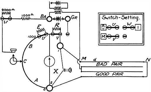
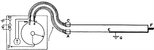
Fig. 609.--Diagram of connections for reading in testing for opens with Leeds and Northrup fault finder, when broken wire and good wire are not in the same cable.
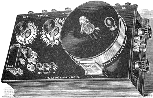
Fig. 610.--Leeds and Northrup potentiometer. It is direct reading from .000001 volt to 16 volts, and with accessories the range may be extended to 1600 volts, and currents may be measured up to 3000 amperes. The instrument has fifteen coils of 5 ohms each, which are in series with an extended wire about 190" long of equal resistance. The electrical circuits are shown in the diagram fig. 611. It is well for the user to open up the potentiometer and make himself familiar with its interior construction, in order to fully understand the operation of the rheostat and other parts. There are no contact resistances in the potentiometer circuit proper. The potentiometer has low internal resistance which gives it the maximum sensibility. Compared with high resistance potentiometer, this is especially advantageous in measuring the electromotive force of thermocouples, and the fall of potential across standard low resistances. As constructed, the last one-tenth volt is covered by the extended wire and the handle which carries the contact point on the wire may be manipulated rapidly so that a fluctuating voltage may be accurately followed. When used with any cadmium cell, the potentiometer is direct reading. The accuracy of the potentiometer resistances can be verified with the facilities of the ordinary laboratory.
Location of Opens.--Case III, in which the broken wire and good wire are not in the same cable. Connect the good wire and broken wire in the same way as shown in fig. 607, and set the pointer for a balance. Call the reading A. Then connect the good wire and the broken wire at the distant end and set the pointer for a new balance. Call this A'. The connections for this reading are shown in fig. 609. The distance to the break will be
d = (A × A' × L) / (1,000(A - A') + A A')
where L is the total length of the broken wire.
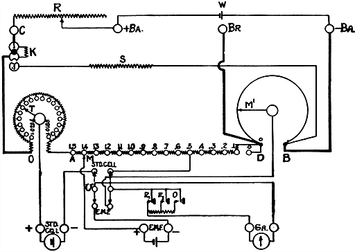
Fig. 611.--Diagram showing connections of Leeds and Northrup potentiometer. The coils in the series AD are each 5 ohms, and between each two there is a brass block with a reamed hole. A pair of flexible cords with taper plug terminals to fit these holes is furnished. These coils can be measured with an ordinary Wheatstone bridge and thus compared with each other to a high degree of accuracy, even if the bridge be not accurate. For potentiometer work, the essential point is that they should be like each other, not that they should be accurately any particular value. In the same way the resistance of the extended wire can be compared with the resistance of the coils in AD. Its resistance should be 1.1 times the value of any coil between A and D. Outside connection with the extended wire may be made by using the posts marked BR and -BA. This adjustment for balancing an unknown electromotive force is accomplished by the manipulation of the two contact points M and M'. The coils AD are arranged in a circle, a revolving switch moving M. A checking device enables the operator to set this switch without taking his eye from the galvanometer. The resistance S is of such value that when it shunts the wire OB, the total resistance between O and B is 1/10 of the same unshunted. When the shunt is applied, provided the total current remain the same, the drop between any two points on AB will be 1/10 of its previous value. The total current will remain the same provided the total resistance in the circuit remain the same. This is accomplished by making the coil K such that it exactly compensates for the reduction in resistance caused by plugging in the shunt coil S. The low scale is applied by moving the plug from the position 1 to the position .1. With this change the potentiometer reads from .16 volt down by indicated steps of .000005 volt. The reading is very simple. For instance, if M stand at 1.2 and M' at 1.35 revolutions, the reading is 1.2135 volts. The resistances of the instrument are wound upon metal spools, and are therefore able to dissipate a comparatively large amount of energy. This allows the potentiometer to be used for pressure measurements up to 16 volts without the use of a volt box.
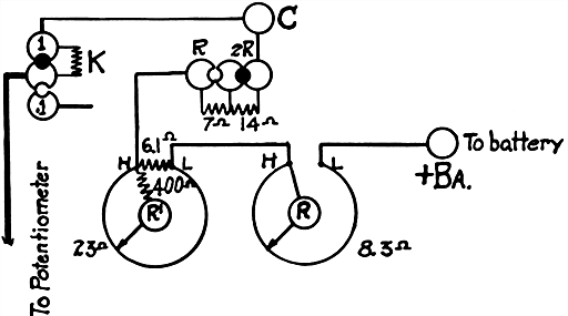
Fig. 612.--Diagram showing actual connections in the rheostat of Leeds and Northrup potentiometer. The figure corresponds to R of fig. 611. The rheostat is mounted in the end of the potentiometer as shown in fig. 610. Rough adjustment of the potentiometer current is made by means of the variable resistance R. Fine adjustment is made by means of the variable resistance R'. It will be noted that the 23 ohm resistance of this latter rheostat is shunted by a resistance of 6.1 ohms, making possible a very fine regulation. Further, there is in series with the moving contact a resistance of 400 ohms, which makes the effect of variable contact resistance negligible. Only one cell of storage battery should be used. When this battery is fresh, the plug shown in the figure at 2R should be inserted at R. This gives the greatest resistance in the rheostat circuit. As the cell runs down, the plug should be changed to 2R. When both plugs are in, the rheostat slide wires are in series with the potentiometer circuit.
EXAMPLE: A pair of wires containing one broken wire was connected with a good pair in a different cable as shown in fig. 607. The reading A was found to be 180. The good and bad wires were then joined at the distant end as in fig. 609, and the reading A was found to be 88. The total length of the bad wire MN was 1.44 miles. Required, the distance to the break. Substituting the values in the formula:
d = 180 × 88 × 1.44 / 1,000(180 - 88) + 180 × 88 = .211 + mile.
To Pick Out Faulty Wires in a Cable.--Short circuit the coils E and R with switches U and V. Set the pointer at 1,000. Connect the post Gr. to ground or the cable sheath and apply the wires one after another to the binding post 2. The galvanometer will deflect for a faulty wire.
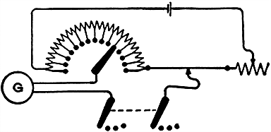
Fig. 613.--Diagram of the Crompton potentiometer. In this instrument the resistance consists of fourteen coils, each of 10 ohms, in series with a straight wire, also 10 ohms resistance, thus forming a system of fifteen equal steps. Across the whole a pressure of 1.5 volt is applied from a secondary cell, thus providing .10 volt per step. Any fraction is then tapped off by means of a radial switch on the resistance coils and a sliding contact on the wire. The standardization is performed by adjusting a resistance in series with the whole until the standard cell employed indicates, by means of the galvanometer G, a balance at the point which represents its electromotive force on the basis given above.
Ques. What is a potentiometer?
Ans. An arrangement of carefully standardized resistances for measuring voltages in comparison with a standard cell. It is used for accurate measurement of voltages, currents, and resistances.
In place of a series of standardized resistances, a slide wire may be used as in fig. 614.
Ques. Describe one form of potentiometer.
Ans. As shown in fig. 614, it consists of a fine German silver wire about 3 feet long stretched between the binding posts A, B, which are attached to a wooden base carrying a scale divided into 1,000 equal parts. There are three circuits, the terminal A being included in each, one including the battery, and the other two the galvanometer. A three point switch connects the galvanometer in series with the standard cell SC, or the cell to be tested C, the circuits being completed by leads terminating in the sliding contacts M and S.
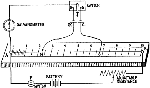
Fig. 614.--Diagram of potentiometer showing method of measuring the voltage of a cell. The potentiometer is simply a high resistance wire of uniform diameter stretched between two binding posts, A and B, in such a way that contact can be made at its ends and along its length. Necessary circuits are plainly shown in the figure; SC, is a standard cell and C, the cell to be tested. M, and S are sliding contacts, connecting with the "slide wire."
Ques. Describe the method of measuring the voltage of a cell with a potentiometer.
Ans. Fig. 614 shows a method of comparing a pressure with that of a standard cell and is applicable whether the pressure of the cell to be tested be greater or less than that of the standard cell. In making the test the switch F is first closed, then the other switch is moved to D, and M adjusted till galvanometer shows no deflection; similarly, the switch is moved to G, and S adjusted till galvanometer shows no deflection. Then, C:SC = AS:AM. from which C = SC × AS ÷ AM.
EXAMPLE.--Let 1.016 volts be the known voltage of the standard cell SC, and the scale reading of AS be 657, and of AM, 225 as in the figure, then
C = (1.016 × 657) / 225 = 2.966 volts
The arrangement may, however, be made direct reading, that is, the slide wire may have a scale of volts instead of lengths or resistances, as follows: Suppose the standard cell to have a pressure of 1.434 volts, the sliding contact M is placed at the reading 1.434, and the adjustable resistance varied till the galvanometer shows no current. This means that the pressure between A and M is 1.434, and consequently the pressures all along the slide can be read off the scale in volts. Hence, when S has been adjusted to balance, the pressure of C is read off the scale in volts.
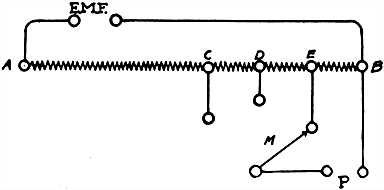
Fig. 615.--To measure a pressure greater than 1.6 volts with Leeds and Northrup potentiometer by using a volt box or multiplier. To measure high voltages it is necessary to connect the voltage across high resistance and to measure on the potentiometer a definite fraction of the total drop. In the figure, AB is a high resistance of which CB is .1th, DB .01th, and EB .001th of the total resistance. The potentiometer reading is accordingly multiplied by 10, 100, or 1,000, depending upon whether the switch M is set on C, D, or E. Resistance boxes for this purpose are called volt boxes, and are constructed to multiply the potentiometer readings by 10, 100, and 1,000. In using them, it is only necessary to connect the unknown E.M.F. at the posts so marked, and the potentiometer to the posts marked P. The potentiometer reading is taken as above and multiplied by a factor depending upon the position of the switch M, which factor is indicated upon the box. It is essential in making these connections that the polarity be carefully observed.
How to Use a Potentiometer.--All connections must be made as indicated by the stamping on the instrument. Particular attention must be given to the polarity of the standard cell, of the battery, and of the voltage, the corresponding + and - signs being marked. If used with a wall galvanometer having a telescope and scale, it will be found convenient to place the potentiometer so that the telescope is directly over the glass index of the extended wire, thus permitting the observer to read the galvanometer deflections and potentiometer settings without changing his position.
Potentiometer Current.--A medium sized storage cell will be found desirable, producing a steady current. Errors in measurements are frequently made by using an unsteady current.
Setting for Standard Cell.--Set the standard cell to correspond with the certified pressure of the standard cell as given in its certificate. In using the potentiometer shown in fig. 610, place the plug in hole 1, and see that it is always in this position when checking against the standard cell. Place the double throw switch at STD. CELL.
Adjust the regulating rheostat until the galvanometer shows no deflection. In making the first adjustment use the key marked R1; when a balance is almost attained, use key R2, and for the final adjustment use key marked R0. This cuts out the resistance in series with the galvanometer and gives the maximum sensibility.
Measurement of Unknown Pressure.--The potentiometer (fig. 610), as ordinarily used, gives direct readings for voltages up to and including 1.6 volts. For pressures higher than 1.6 volts, a volt box or multiplier should be used. After obtaining the standard cell balance, as previously described, place the double throw switch in the position marked E.M.F. The balance for the unknown E.M.F. is obtained by manipulating the tenths switch and rotating the contact on the extended potentiometer wire. The final position of the two contacts in conjunction with the position of the plug at the left of the instrument indicates the voltage under test.
As directed above, use key R1 for rough adjustment, R2 for intermediate adjustment, and key R0 for final adjustment.
Plug at 1 gives readings for voltage directly from settings of tenths switch and extended wire contact.
Plug at .1 shunts the potentiometer circuit so that the voltage measured is .1 of the reading taken directly from the scale. Hence, the readings taken from the setting of the tenths switch and the slide wire contact must be divided by 10.
To Balance Galvanometer for Unknown Voltage.--Place plug in hole 1 (fig. 610) for voltages up to 1.6, and in hole .1 for voltages up to .16. Rotate the tenths switch until a condition of balance is obtained exactly or approximately. To secure an exact balance, rotate the contact on the extended wire. The unknown voltage can now be read directly from the position of the tenths switch and the extended wire contact if plug be at 1, or by dividing by 10 if plug be at .1.
EXAMPLE.--A balance was obtained with the tenths switch at 1.3, the extended wire contact at 176 and the plug at 1. The voltage under test, therefore, is 1.3176. If the plug at .1 had been used, the same reading would have indicated .13176.
To ascertain if the current in the potentiometer circuit has altered during a measurement, it is only necessary to plug in at 1, place the double throw switch on STD. CELL and close the galvanometer key. No deflection indicates that the current has not changed. If the galvanometer deflect, the regulating rheostat must again be adjusted until the galvanometer shows no deflection.
To Measure Voltages from 1.6 to 16.--Pressures up to 16 volts may be measured by using a greater voltage across the BA posts (fig. 615). For this purpose a battery of about 20 volts should be used. Insert the large plug at .1 and throw the switch to STD. CELL, then balance the galvanometer by means of the regulating rheostat. When the rheostat has been set to secure a balance, insert the large plug at 1, set the switch on E.M.F. and read the voltage in the usual manner. Multiply the reading by 10.
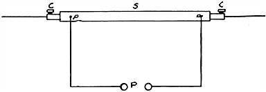
Fig. 616.--Measurement of current with potentiometer. This is done by measuring the drop in volts across a known low resistance. In the figure S is the standard resistance, and on it are the pressure terminals pp, and the current terminals CC. The potentiometer is connected to the shunt through the posts marked P. The resistance between the points pp is adjusted to an even fraction of an ohm. These resistances are so chosen that in order to determine the current passing through the shunt, after having obtained a potentiometer balance it is only necessary to multiply the potentiometer reading by a simple factor. For instance, in using a .01 ohm standard. It is only necessary to multiply the potentiometer reading by 100, which gives the current reading in amperes; similarly, a .1 ohm requires multiplication by 10, and a .001 ohm by 1,000.
Care of Potentiometer.--The slide wire, although protected to a great extent by the hood, in time accumulates dust and dirt with a thin film of oxide. This will tend to increase the resistance in this part of the circuit owing to poor contact. This wire should, therefore, be cleaned occasionally.
To do this, unscrew the stop against which the hood strikes when turned to read zero; then remove the hood and rub the entire slide wire vigorously with a soft cloth dipped in vaseline. Do not use emery or sand paper as this will destroy the uniformity of the slide wire. Clean also the steel contact which rubs on the wire, as this becomes glazed after much use. When the potentiometer is not in use, the hood should be screwed all the way down, and the lid put in place to exclude dust.
If it be used in a chemical factory, laboratory, or any place where acid fumes are prevalent, this latter precaution is important, because the fumes may attack the slide wire.
It is also well to keep the contact surfaces of the switch studs clean and bright by wiping them occasionally with a soft cloth dipped in vaseline.
Res. of leads on each end is equal to 10 divisions of slide wire. The slide wire is divided into 1000 parts--20 for the leads, or 980 divisions. Calibrated scale on Galvanometer:
Fig. 617.--Diagram of Leeds and Northrup bridge for locating faults in power circuits, showing arrangement of the connections including the lead cables and galvanometer contacts. Make connections as shown. The clamps must be so fastened at A and C that the contact resistances will be very small. This contact resistance will figure as an error in the measurement. If, for instance, the contact resistance were equal to .001 of an ohm, and the wire were of such a size that .001 of an ohm were equal to the resistance of 20 feet of the cable, there would be an error of 20 feet in the location of the fault. For this reason all contact resistances throughout the loop from A to C must be extremely small. The battery is to be connected to the posts marked Ba., and the post marked Gr. is to be grounded. It will very frequently happen that the ground is to the cable sheath or some other conductor. In this case, the binding post Gr. should be grounded to this conductor. Sufficient battery should be used to give a readable deflection on the galvanometer for a small movement of the contact on the bridge wire. The fault is located by the usual Murray formula. If, for instance, the galvanometer show no deflection when the contact is at 300 on the scale, it would indicate that the fault is at a distance from A equal to .003 of the total length of the loop from A to C. A testing current of five amperes may be used with this bridge. In cases of necessity, this current may be increased to eight amperes, but when this current is used it should not be allowed to pass through the bridge for a longer time than is necessary. It frequently happens that small faults which have a very high resistance develop in high pressure cables. Such faults are likely to break down and result in damage and should be located. It is usually impossible to locate these faults until they have been partially carbonized. This must be done by applying a sufficiently high voltage between the cable and the sheath (or whatever it is grounded on) to break down the fault. In order to prevent the breaking down process from resulting in a serious burn out a high resistance must be placed in the circuit which will prevent an excessive current, or the circuit must be carefully fused. The former procedure is the better.
Location of Faults where the Loop is Composed of Cables of Different Cross Sections.--Faults in loops of this character may be located with the same degree of accuracy as those in loops of a uniform cross section, provided the length and cross section of each length of cable are known. An example will illustrate the method:
In the diagram, fig. 617, assume the length of the cable AE to be 550 yards of 25,000 cir. mil., EF, 500 yards of 40,000 cir. mil., and FC, 1,050 yards of 30,000 cir. mil. These lengths must be reduced by calculation to equivalent lengths of one size, and for this purpose it is best to select the largest size. The results of this calculation are as follows:
550 yds. of 25,000 cir. mil. = 880 yds. of 40,000 cir. mil. 500 " " 40,000 " " = 500 " " 40,000 " " 1,050 " " 30,000 " " = 1,400 " " 40,000 " "
This makes the total resistance of the loop equivalent to 2,780 yards of 40,000 cir. mil. If the contact show a balance for a reading of 372.5, this indicates that the fault is at a distance of 372.5/1,000 of 2,780 = 1,035.5 equivalent yards. Of this, 880 are in the stretch A E. Consequently the fault is:
1,035.5 - 880 = 155.5 yards from E.
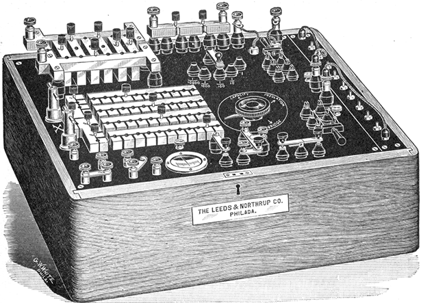
Fig. 618.--The Fischer portable cable testing set, designed for locating crosses, grounds and breaks in cables, also for conductor and liquid resistance measure. The distinguishing feature of the set is the master switch. By means of this switch, connections can be made for the various tests by a single movement, thus avoiding the labor and time which have to be expended in interchanging the connections and memorizing the rather complicated scheme of connections.