Chapter XXVIII · AMMETERS, VOLTMETERS AND WATTMETERS.
Reading edition
An ammeter or ampere meter is simply a commercial form of galvanometer so constructed that the deflection of the needle indicates directly the strength of current in amperes. A good ammeter should have a very low resistance so that very little of the energy of the current will be absorbed; the needle should be dead beat, and sufficiently sensitive to respond to minute variations of current.
According to the principle of operation, ammeters and voltmeters are classified as:
Moving iron;
Moving coil;
Solenoid or plunger;
Magnetic vane;
Hot wire;
Electrostatic;
Astatic;
Inclined coil;
Fixed and movable coil.
Again, they are divided according to their use into two classes:
Portable type;
Switchboard type.
Milli-ammeters or milli-voltmeters are instruments in which the scale is graduated to read directly in thousandths of an ampere or thousandths of a volt respectively.
Ques. Describe the moving iron type instrument.
Ans. The arrangement of the working parts are shown in fig. 620. A soft iron needle N, is pivoted inside of a coil C, and is held out of line with the axis of the coil by means of a permanent magnet M, when the instrument is idle. In this position, a pointer P, which is attached to the needle, stands at the zero mark of the scale S. If a current be passed through the coil, magnetic lines of force are set up in its center, which tend to pull the needle into line with them, and therefore with the axis of the coil. This pull is resisted by the permanent magnet M, and the amount of deflection of the needle from the zero position depends upon the strength of the current or the voltage according as the coil is wound to indicate amperes or volts.
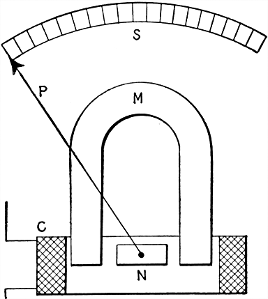
Fig. 620. Moving iron type instrument. The essential parts are: N, soft iron needle; C, coil; M, permanent magnet; P, pointer; S, scale. Current passing through the coil acts on the needle, causing it to turn against the restraining force due to the influence of the permanent magnet.
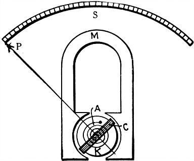
Fig. 621.--Moving coil type instrument. The essential parts are: A, spiral spring; C, coil; K, soft iron core; M, permanent magnet; P, pointer; S, scale. Current passing through the coil causes the moving system to turn against the restraining force due to the influence of the permanent magnet.
Ques. Describe a moving coil instrument.
Ans. This type of instrument is shown in fig. 621. It consists of a moving coil C, to which is attached the pointer, and which is pivoted between the poles of a permanent magnet M. The coil moves between these poles and a fixed soft iron core K, and is held in the normal position by two spiral springs A, above and below the core. The springs also serve to make electrical connection with the coil C.
When a current passes through the coil, magnetic lines are set up in it which are at an angle to those passing from one pole of the permanent magnet to the other. The lines of force, which formerly passed from one pole of the magnet to the other by straight lines or by short curved ones, are "stretched" on account of the field produced by the current in the coil, and, in trying to shorten themselves, tend to twist the coil through an angle. This tendency to move is resisted by the two spiral springs, hence the coil moves until equilibrium is established between the two opposing forces.
The amount of deflection of the pointer depends, either upon the current strength, or the voltage according to the winding of the coil.
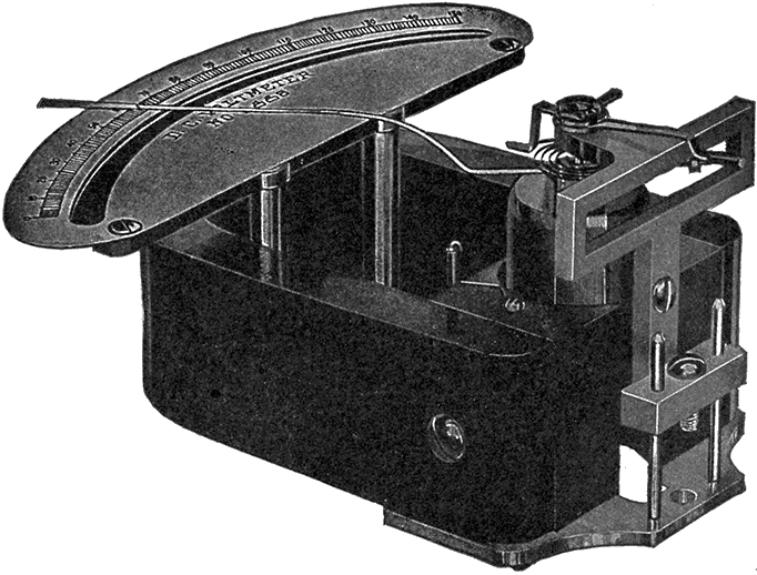
Fig. 622.--Keystone voltmeter; view showing the moving element being withdrawn by loosening one screw. These instruments are constructed on the d'Arsonval system, the moving element being shown in detail in figs. 623 and 624. The entire system is mounted upon a solid metal base plate. The permanent field magnet is made of a single piece of magnet steel, and the pole pieces are of soft steel, permanently secured to the magnet in order that the distribution of the magnetic flux will not be changed by removal and replacement of the pole piece. Accordingly the moving mechanism is mounted separately from the field, so that it can be readily lifted from the field without removing the pole pieces. The function of the core is to secure a uniform field. The moving coil is wound upon a form of aluminum, which serves the purpose of damping by the generation of eddy currents. The winding of the coil is of fine copper wire, to which current is conveyed by means of the controlling springs and which, in the case of a voltmeter, is connected in series with a resistance, and in the case of an ammeter, across the terminals of a shunt.
Ques. How does the winding differ in ammeters and voltmeters?
Ans. An ammeter coil consists of a few turns of heavy wire (when designed to carry the full current), while a voltmeter coil is wound with many turns of fine wire. Thus, the ammeter is of low resistance, and the voltmeter of high resistance.
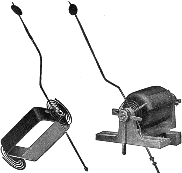
Fig. 623.--New moving element of Keystone instruments, weight 1.2 grams.
Fig. 624.--Moving element of Keystone instruments assembled in bearing. The moving element consists of coil, counterpoise and pointer. The mechanical connections are made by means of screws and steady pins. In order to adjust for slight set or subset of spring under long use a zero adjuster is provided by means of which this set can be connected and the pointer brought back to zero.
Ques. Why is a high resistance coil used with a voltmeter?
Ans. As actually constructed, most voltmeters are simply special forms of ammeter. From Ohm's law, the current through a given circuit equals the pressure at its terminals divided by its resistance. Hence, if a high resistance be connected in series with a sensitive ammeter that will measure very small currents, then the current passing through the circuit is directly proportional to the voltage at its terminals, and the instrument may be calibrated to read volts.
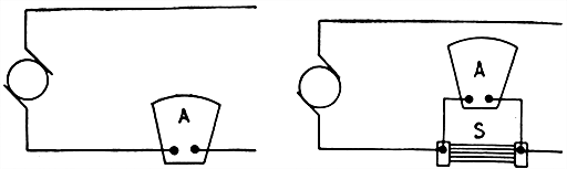
Figs. 625 and 626.--Connections for series and shunt ammeters. When the construction is such that all the current passes through the instrument, it is connected as in fig. 625, but where the instrument is designed to take only a fraction of the current, it is connected across a shunt, as in fig. 626, a definite proportion of the current passing through the instrument and the remainder through the shunt.
Ques. Into what two classes may ammeters be divided?
Ans. They are classed as series or shunt according to the way they are designed to be connected with the circuit.
Ques. What determines the mode of connecting ammeters?
Ans. When the wire of the ammeter coil is large enough to carry the whole current, it is connected in the circuit in series as shown in fig. 625. If, however, the wire be small, the instrument is connected in parallel with a shunt of low resistance, so that it only carries a small part of the current, as in fig. 626.
For circuits which carry large currents, the shunt connection is always used, because otherwise the coil of the ammeter would have to be very heavy and the instrument correspondingly bulky.
Ques. How are shunt ammeters arranged to correctly measure the current?
Ans. The coil is arranged so that a definite proportion of the whole current passes through it. A large conductor of low resistance is connected directly between the two terminals or binding posts of the instrument; the coil is connected as a shunt around a definite part of this main conductor; then, since the two are connected in parallel and each branch has a definite resistance, the current divides between the two branches directly in proportion to their relative conductivities, or inversely according to their resistances. The coil, therefore, takes a definite part of the whole current, and the force moving it and its pointer away from the zero position is directly proportional to the whole current. Hence, by providing a proper scale, the value of the entire current will be indicated.
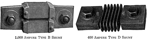
Figs. 627 and 628.--Westinghouse ammeter shunts. These shunts are used where heavy currents are to be measured. The shunt is connected in series with the bus bar or circuit to be measured, and its terminals are connected by means of small leads to the ammeter or other instrument. These shunts are designed to have approximately 50 millivolts drop at full rated current. They are intended primarily for Westinghouse meters, but can be used satisfactorily with any meter requiring 50 millivolts for full scale deflection.
Ques. How is a voltmeter connected?
Ans. A voltmeter is always connected to the two points, whose difference of potential is to be measured.
For instance, to measure the voltage between the two sides A and B of the circuit shown in fig. 629, one terminal of the voltmeter is connected to wire A, and the other to wire B. If the "drop" or difference in voltage through a certain length of wire L, of a circuit, as from A to B in fig. 630 is to be determined, one terminal of the voltmeter is connected to A and the other to B. In a similar manner is found the drop through a lamp.

Fig. 629.--Voltmeter connection for measuring the pressure in an electric circuit. The voltmeter is connected in parallel in the circuit at the point where the voltage is to be measured.
Fig. 630.--Voltmeter connection for measuring the "drop" or fall in voltage in a certain length of wire, as for instance, the length between the points A and B. The voltmeter is shunted between the two points whose pressure difference is to be measured.
Ques. What is the difference between a voltmeter and an ammeter?
Ans. A voltmeter measures pressure, while an ammeter measures current. As actually constructed, most voltmeters are simply special forms of ammeter.
If a high resistance be connected in series with a sensitive ammeter that will measure very small currents, then the current passing through the circuit is directly proportional to the pressure or voltage at its terminals and the instrument may be calibrated to read volts.
Ques. Explain the term "calibrate."
Ans. To calibrate a measuring instrument is to determine the variations in its readings by making special measurements, or by comparison with a standard.
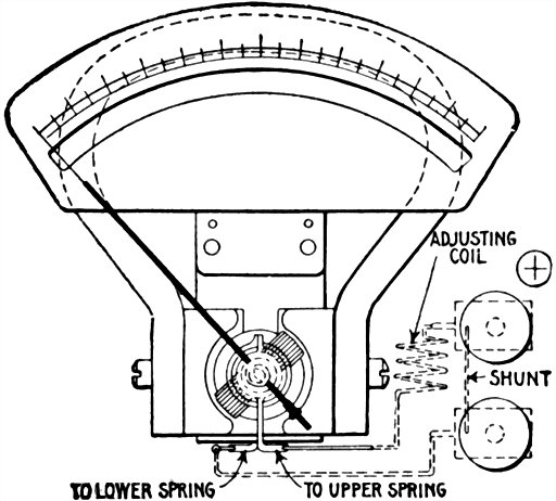
Fig. 631.--Weston ammeter; view showing shunt enclosed within the instrument. Weston instruments are direct reading and dead beat. Although the scales have practically uniform divisions, it is not assumed in the calibration that they are uniform, and the scales are not printed or engraved. The method of calibration consists in laying out each large division of the scale by comparing the instrument with a standard, and then inking in the division lines so found. The smaller divisions between the large ones are then equally spaced and marked by a mechanical method.
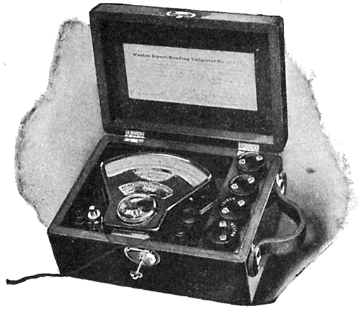
Fig. 632.--Weston portable voltmeter, inspector's style. This instrument is provided with a reversing key. Instead of the regular binding posts, pins are used with which connections are made by means of contact cups attached to flexible cords. These contact cups are convenient in making connections, or in changing quickly from one range to the other, if the instrument have a double scale. Connections for the different ranges are made in precisely the same way as with the regular double scale voltmeters. For the upper scale values, the contact pin to the right and the front contact pin to the left being taken, and for the lower scale values, the left contact cup is changed to the rear contact pin.
Ques. Describe a solenoid or plunger ammeter.
Ans. This type consists of a "plunger" or soft iron core arranged to enter a solenoid. Current being passed through the wire of the solenoid causes the core to be more or less attracted against a restraining force of gravity or springs. A pivoted pointer attached to the core indicates the current value on a graduated dial as shown in fig. 633.
Ques. What are the objections to plunger instruments?
Ans. They are not reliable for small readings, and are readily affected by magnetic fields.
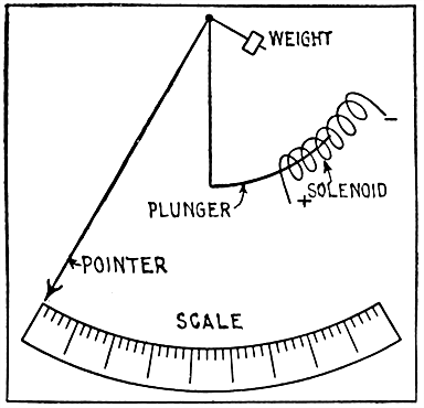
Fig. 633.--Plunger type instrument. The current to be measured passes through the solenoid, producing a magnetic effect on the soft iron plunger which tends to draw it into the coil, and thus cause the pointer to move over the graduated scale. The distance the rod moves depends on the value of the restraining force (which may be springs or gravity), the coil winding, and strength of current. The winding consists of a few turns of heavy wire for an ammeter, and a large number of turns of fine wire when constructed as a voltmeter. Since the iron has a certain amount of residual magnetism, the deflection with smaller following large currents is more than would be produced by the same current following a smaller one. The instrument therefore is less reliable than the usual types.
Ques. Describe a magnetic vane instrument.
Ans. It consists of a small piece of soft iron or vane mounted on a shaft that is pivoted a little off the center of a coil as shown in fig. 634. The principle upon which the instrument works is that a piece of soft iron placed in a magnetic field and free to move will move into such position as to conduct the maximum number of lines of force. The current to be measured is passed around the coil producing a magnetic field through the center of the coil. The magnetic field inside the coil is strongest near the inner edge, hence, the vane will move against the restraining force of a spring so that the distance between it and the inner edge of the coil will be as small as possible. A pointer, attached to the vane shaft moves over a graduated dial.
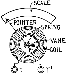
Fig. 634.--Magnetic vane instrument. A soft iron vane, eccentrically pivoted within a coil carrying the current to be measured, is attracted toward the position where it will conduct the greatest number of magnetic lines of force against the restraining force of a spring or equivalent.
Ques. Describe an inclined coil instrument.
Ans. As shown in fig. 635, a coil carrying the current, is mounted at an angle to a shaft to which is attached a pointer. A bundle of iron strips is mounted on the shaft. A spring restrains the shaft and holds the pointer at the zero position when no current is flowing. When a current is passed through the coil, the iron tends to take up a position with its longest sides parallel to the lines of force, which results in the shaft being rotated and the pointer moved on the dial, the amount of movement depending upon the strength of the current in the coil.
The coils for large sizes are generally wound with a few turns of flat insulated copper ribbon. The instruments are adapted to either direct or alternating currents but are recommended for alternating currents.
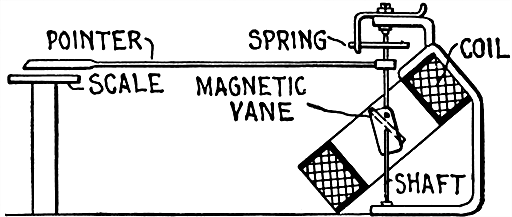
Fig. 635.--Thompson inclined coil ammeter. It is constructed on the magnetic vane principle in which an iron vane is attracted by the magnetic field due to the coil, so as to turn itself parallel with the axis of the coil, the latter being inclined with respect to the axis of the vane. The voltmeter of this type has a similarly placed stationary coil, but in place of the iron vane, is provided with a moving coil in series with the other coil. The restraining force in each case being that due to springs. Figs. 636 and 637 show the actual construction of inclined coil instruments.
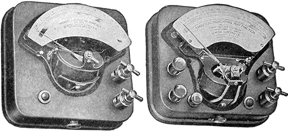
Figs. 636 and 637.--Thompson inclined coil portable indicating instruments. Fig. 636, ammeter type P interior; fig. 637, wattmeter, type P, interior. These instruments, though primarily designed for use on alternating current circuits, may also be used on direct current circuits, by making reversed readings and taking the mean as the true indication. The voltmeters and wattmeters are constructed on the dynamometer principle and the ammeters, on the magnetic vane principle. The voltmeters and wattmeters are provided with a contact key which may be locked in position, enabling the instruments to be left constantly in circuit. The movements of the pointer are damped by means of an air vane; there is also a friction damping device operated by a small button to check excessive oscillations of the pointer. The inclined coil instruments are so designed that the torque is sufficiently high to insure the pointer assuming a definite position with each change in current value.
Ques. What is the principle of the hot wire instrument?
Ans. Its action depends upon the heating of a conductor by the current flowing through it, causing it to expand and move an index needle or pointer, the movements of which, by calibration, are made to correspond to the pressure differences producing the actuating currents.
Ques. What are the characteristics of hot wire instruments?
Ans. Voltmeters of this type are not affected by magnetic fields, and as their self-induction is small, they can be used on either direct or alternating currents; but they possess certain serious defects: they consume more current than the other types; cannot be constructed for small readings; are liable to burn out on accidental overloads; and are somewhat vague in the readings near the zero point and are sometimes inaccurate in the upper part of the scale.
Ques. Describe the construction and operation of the Whitney hot wire instruments.
Ans. As shown in fig. 638, a wire AX, of non-oxidizable metal, of high resistance and low temperature coefficient, passes over a pulley B mounted on the shaft C. The ends of the wire are attached to the plate E at its ends F and G, the wire being insulated from the plate at G. A spring H holds the wire in tension and takes up the slack due to the expansion caused by the heating of the wire when a current passes through it. The current flows only in the portion of the wire marked A, between the plate E and the pulley B up to the point K where the connection is shown. When a current flows through the wire A, the spring takes up the slack, pulls A around B, and causes B to rotate upon its shaft C. It is clear, that a pointer attached to C, would indicate on a scale the movement of B and C, but as this movement is very slight, a magnifying device will be required. This device consists of a forked rod L, rigidly attached to the shaft C, and carrying at its lower end a silk fibre fastened to the fork and passing around a pulley M, to which a pointer N is attached. For direct current measurements only an electromagnetic system is used.
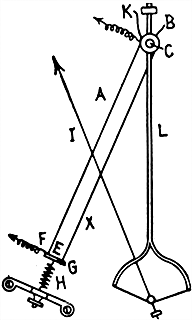
Fig. 638.--Diagram showing principle and construction of the Whitney hot wire instruments. The action of instruments of this type depends on the heating of a wire by the passage of a current causing the wire to lengthen. This elongation is magnified by suitable mechanism and transmitted to the pointer of the instrument.
Ques. What is the principle of electrostatic instruments?
Ans. The action of these instruments depends upon the fact that two conductors attract one another when any difference of electric pressure exists between them. If one be delicately suspended so as to be free to move, it will approach the other.
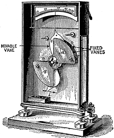
Fig. 639.--Kelvin electrostatic voltmeter; a form of instrument designed for measuring high pressures up to 200,000 volts. The instrument, as illustrated, consists of fixed and movable vanes with terminals connecting with each. These vanes which act as condensers take charges proportional to the potential difference between them, resulting in a certain attraction which tends to rotate the movable disc against the restraining force of gravity. In the figure aa and b are two fixed vanes and c a movable vane, carrying a pointer and having a proper weight at its lower end.
Ques. Describe the Kelvin electrostatic voltmeter.
Ans. A simple form consists, as shown in fig. 639, of a metal case containing a pair of highly insulated plates, between which a delicately mounted paddle shaped needle is free to move. When the needle is connected to one side of a circuit and the stationary plates to the other side, the needle is attracted and moves between them as indicated by the pointer. Adjusting screws at the lower end of the needle allow it to be balanced so that its center of gravity is somewhat below the center of suspension. Gravity then is the restraining force.
The range of the instrument may be changed by hanging different weights upon the needle. By increasing the number of blades the instrument can be made to measure as low as 30 volts. The form having two stationary blades and one movable blade is suitable for measuring from 200 to 20,000 volts. The quadrant electrometer or laboratory form will measure a fraction of a volt.
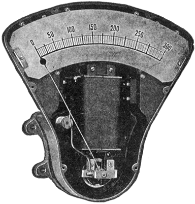
Fig. 640.--Thompson astatic instrument without cover. When current passes through the coils of the moving element, the lines of force parallel to the shaft produce a torque which tends to turn the shaft and cause the needle to travel across the scale. This action is, of course, opposed by the magnetic field at right angles to the shaft acting on the two pieces of magnetic metal. These astatic instruments have no controlling springs. The two small silver spirals which conduct the current to and from the armature are made of untempered silver and exert no force as springs. The actuating and restraining forces are dependent upon the same electromagnets. The damping effect in these instruments is produced by an aluminum disc moving in a magnetic field, and is proportional to the square of the magnet strength.
Ques. Explain the construction and principle of the Thompson astatic instruments.
Ans. The fields of these instruments are electromagnets wound for any specified voltage and provided with binding posts separate from the current posts of the instrument. The moving coils are mounted upon an aluminum disc and are located in a magnetic field which is parallel to the shaft and astatically arranged. Two small pieces of magnetic metal are rigidly mounted on the shaft and the astatic components of the magnetic field, which are perpendicular to the shaft, tend to keep the pieces of magnetic metal in their initial positions. When current passes through the coils of the moving element, the lines of force parallel to the shaft produce a torque which tends to turn the shaft and cause the needle to travel across the scale. This action is, of course, opposed by the magnetic field at right angles to the shaft acting on the two pieces of magnetic metal. There are thus no restraining springs, current being conveyed to the moving coil by torsionless spirals of silver wire. Thompson astatic instruments can be provided with polarity indicators, a red disc showing on the scale card where the poles are reversed.
The effect of external fields is eliminated by the astatic arrangement of the fields and the moving parts. A field which tends to increase the torque on one side of the armature diminishes it to a corresponding degree on the other side. The damping effect in these instruments is produced by an aluminum disc moving in a magnetic field.
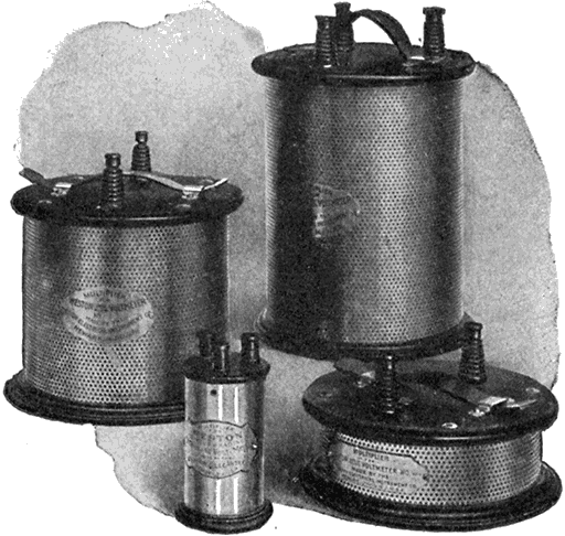
Fig. 641 to 642.--Multipliers for Western standard portable voltmeters. Multipliers are resistance boxes, the coils in which are highly insulated, and are adjusted so that the readings of the instrument may be multiplied by any desired constant. Multipliers are usually constructed so that the indications of the pointer, multiplied by 2, 5, 10, 20 or 50, will give the voltage of the circuit. By the use of multipliers the range of voltmeters may be increased to any practical limit.
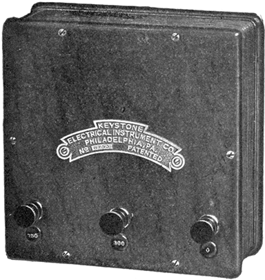
Fig. 643.--Portable multiplier for portable voltmeter. A multiplier is used for increasing the readings of voltmeters, and consists of resistance coils placed in a portable case. A multiplier is connected in series with the voltmeter and must be adjusted for the instrument with which it is to be used, because the resistance coil must be a multiple of the voltmeter resistance. For instance, a multiplier with a value of 10, used with a 6 volt voltmeter or 521 ohms would measure about 5,215 ohms; one with a value of 40, would equal about 20,860 ohms. The multiplier 10 would give a total scale value of 60, and the multiplier 40, a total scale value of 240 volts to the 6 volt instrument. A multiplier is of considerable value in that it does away with the necessity of having a number of voltmeters of different ranges. The instrument here illustrated has a range of 150 volts.
Ques. What are multipliers?
Ans. These are extra resistance coils which are connected in series with a voltmeter for increasing its capacity or readings. They are put up in portable boxes, and must be adjusted for each particular voltmeter as the resistance of a multiplier coil must be a multiple of the resistance of the voltmeter itself.
Ques. What is an electro-dynamometer?
Ans. An instrument for measuring amperes, volts, or watts by the reaction between two coils when the current to be measured is passed through them. One of the coils is fixed and the other movable.
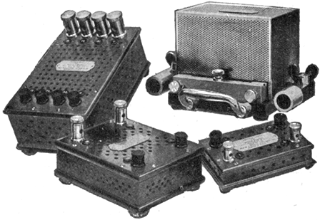
Figs. 644 to 645.--Western standard portable shunts. The milli-voltmeters used in connection with these shunts read directly in amperes. Shunts of different capacities can be adjusted to the same instrument, and it can, therefore, be used to measure a current of 2,000 amperes with the same degree of accuracy as a current of 1 ampere. In selecting shunts of different capacities for use in connection with one instrument it should be considered that the higher ranges must be even multiples of the lower one in order to suit the same scale on the instrument.
Ques. Describe the Siemens' electro-dynamometer.
Ans. The essential parts are shown in fig. 646. The fixed coil A, composed of a number of turns of wire is fastened to a vertical support, and surrounded by the movable coil B of a few turns, or often of only one turn. The movable coil is suspended by a thread and a spiral spring C, below the dials which are fastened at one end to the movable coil and at the other end to a milled headed screw D, which can be turned so as to place the planes of the coil at right angles to each other, and to apply torsion to the spring to oppose the deflection of the movable coil for this position when a current is passed through the coils. The ends of the movable coil dip into two cups of mercury E, E', located one above the other and along the axis of the coils so as to bring the two in series when connected to an external circuit. The arrows show the direction of current through the two coils. An index pointer F is attached to the movable coil. The upper end of this pointer is bent at a right angle, so that it swings over the dial between two stop pins G, G', and rests directly over the zero line when the planes of the coils are at right angles to each other. A pointer H is attached to the torsion screw D, and sweeps over the scale of the dial. The spring is the controlling factor in making the measurement.
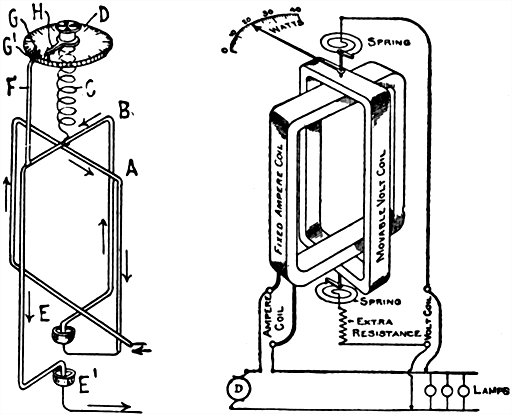
Fig. 646.--Diagram of Siemens' electro-dynamometer. It consists of two coils on a common axis, but set in planes at right angles to each other in such a way that a torque is produced between the two coils which measures the product of their currents. This torque is balanced by twisting a spiral spring through a measured angle of such degree that the coils shall resume their original relative positions. If the instrument be used for measuring current, the coils are connected in series, and the reading is then proportional to the square of the current. If used as a wattmeter, one coil carries the main current and the other a small current, which is proportional to the pressure. The reading is then proportional to the power in the circuit.
Fig. 647.--Diagram showing connections of Siemens' electro-dynamometer as arranged to read watts.
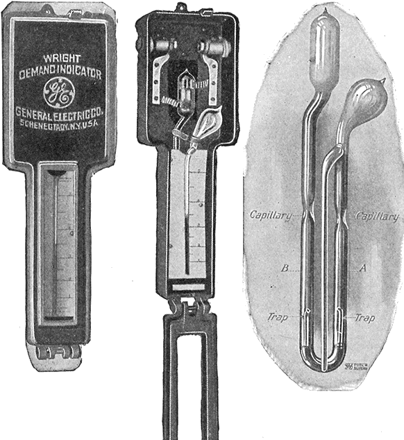
Figs. 648 to 650.--Wright demand indicator. This is a device for registering the maximum ampere demand of appreciable duration in any electrical circuit. It may be used on either direct or alternating current circuits. The essential features and principle are as follows: A liquid is hermetically sealed in a glass vessel consisting of two bulbs connected by a "U" tube, and a central tube called the "index" tube, connected to the upper end of the right hand side of the "U." Around the left hand or heating bulb, is placed a band of resistance metal, through which the current to be measured is passed, or a definite shunted portion of it. The heating effect of the current increases the temperature of the left hand bulb, causing the air to expand which forces the liquid up the right hand side of the "U" tube and into the index tube, where it remains until the indicator is reset. The height of the liquid in the index tube as shown by the scale, indicates the maximum current which has passed through the indicator. It is the difference in temperature of the air in the two bulbs which causes the flow of the liquid. Any change in external temperature causes equal effect in both bulbs and therefore does not affect the reading.
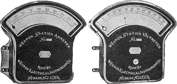
Figs. 651 and 652.--Weston illuminated dial station voltmeter and ammeter. The voltmeter has two indices, a pointed index for close readings and an index called the normal index, which enables a slight deviation from the normal voltage to be seen from a long distance. The "normal index" is inside the case and terminates in a circular disc of blackened aluminum. The disc is adjusted from the outside of the case by hand, by means of the knurled knob seen on the front of the case, so that it is directly below the point of normal voltage. When the indicating index reaches the point of normal voltage, the disc of the normal index appears in the center of the circular opening of the indicating index, a narrow ring of white being visible, encircling the disc of the normal index. The ammeter depends for its operation upon the fall of potential between two points of the circuit carrying the main current, and requires a difference of only about .05 volt to give a full scale deflection. When a maximum deflection is secured, the current passing through the instrument is never more than .07 ampere irrespective of the total capacity of the instrument. A separate shunt is used which is placed at the back of the switchboard. In many cases, a special shunt can be dispensed with and a short section of the mains on the switchboard, or the mains leading from the dynamo, can be used instead. On the basis of one square inch cross section per 1,000 amperes, a length of about 5 feet of copper conductor would be required as a shunt, in which case however, this section of the conductor must be adjusted with precision.
Ques. Explain the operation of the Siemen's electrodynamometer.
Ans. In fig. 646, when a current is passed through both coils, the movable coil is deflected against a stop pin, then the screw D is turned in a direction to oppose the action of the current until the deflection has been overcome and the coil brought back to its original position. The angle through which the pointer of the torsion screw was turned is directly proportional to the square root of the angle of torsion. To determine the current strength in amperes, the square root of the angle of torsion is multiplied by a calculated constant furnished by the makers of this instrument.
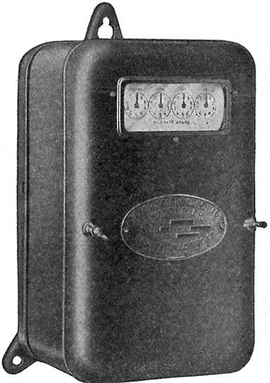
Fig. 653.--Thompson watt hour meter (type C-6). This form is furnished with side connections, the line wires entering at the left and the load wires at the right. Both sides of the system are carried through the meter in all sizes up to and including the 50 ampere size. In meters of larger ampere capacities, a voltage tap is used.
Ques. How is the electrodynamometer adapted to measure volts or watts?
Ans. When constructed as a voltmeter, both coils are wound with a large number of turns of fine wire making the instrument sensitive to small currents. Then by connecting a high resistance in series with the instrument it can be connected across the terminals of a circuit whose voltage is to be measured. When constructed as a wattmeter, one coil is wound so as to carry the main current, and the other made with many turns of fine wire of high resistance suitable for connecting across the circuit. With this arrangement, the force between the two coils will be proportional to the product of amperes by volts, hence, the instrument will measure watts.
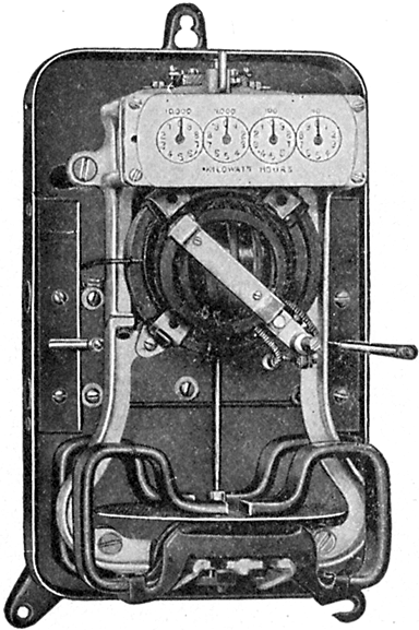
Fig. 654.--Interior view of Thompson watt hour meter (type C-6). Capacity: 5 to 600 amperes, two wire, and 5 to 300 amperes, three wire; 100 to 250 volts. The meter is supported by three lugs, the upper one of which is keyholed, and the lower right hand one slotted. This permits rapid and accurate levelling as the top screw can be inserted and the meter hung thereon approximately level. The right hand screw may then be placed in position and the meter adjusted as may be required before forcing the screw home.
Ques. Describe briefly the construction of the Thompson recording wattmeter.
Ans. It consists of four elements: 1, a motor causing rotation; 2, a dynamo providing the necessary load or drag; 3, a registering device, the function of which is to integrate the instantaneous values of the electrical energy to be measured; and 4, means of regulation for light and full load.
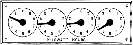
HOW TO READ A METER
Fig. 655.--Recording dials of watt hour meter, illustrating method of reading electric meters. The unit of measurement of electrical energy is the watt hour. 1,000 watt hours make or equal 1 kilowatt hour. Some electric meters have 4 dials, the extreme right hand dial of which registers in kilowatt hours, while others have 5 dials, the extreme right hand dial of which registers in tenths of kilowatt hours. In making out bills to customers the extreme right hand dial of a 5 dial meter is ignored in order that the "state of meter" shown on bills uniformly requires the addition of 3 ciphers to correctly express the registration in watt hours. Each division on the right hand dial (ignoring the 5th dial mentioned) denotes 1,000 watt hours or 1 kilowatt hour; on the next dial 10 kilowatt hours, on the next dial 100 kilowatt hours and on the left hand dial 1,000 kilowatt hours. One complete revolution of any dial causes the hand on the dial immediately to its left to move forward one division. To take a statement from the meter begin at the left and set down for each dial the lower figure next to each hand, not necessarily the figure nearer the hand. In the above example the statement is 1,726 kilowatt hours or 1,726,000 watt hours. Subtract the previous statement to arrive at registration for a given period. Some meters are subject to a multiplying constant so stated on their face and the registration of such meters must be multiplied by the constant as shown, to determine the actual consumption of electrical energy. The constant is the measure of the mechanical adjustment in the register of the meter and is the ratio between the registration of the dial hands and the true consumption. This adjustment is made always by the manufacturer of the meter and is never changed in service.
Ques. What is the action of the motor in the Thompson watt hour meter?
Ans. It rotates at very slow speed, and since there is no iron in its fields and armature, it has very little reverse voltage. Its armature current, therefore, is independent of the speed of rotation, and is constant for any definite voltage applied at its terminals.
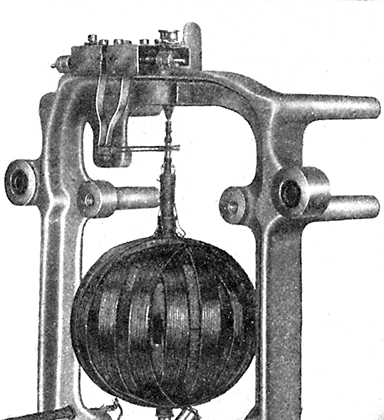
Fig. 656.--Interior of Thompson watt hour meter (type C-6) showing armature, small commutator and gravity brushes. A spherical armature moving within circular field coils is the construction adopted in this meter. The armature is wound on a very thin paper shell, stiff enough to withstand the strain due to winding and subsequent handling. The wire composing the armature is of the smallest gauge consistent with mechanical strength. The field coils, as before stated, are circular, and are placed as near each other as possible, one on either side of the armature, with the internal diameter just sufficient to give the necessary clearance for the rotating element. This construction prevents magnetic leakage. Ribbon wire is employed for the field coils, thus economizing space and further carrying out the idea of concentration.
The torque of this motor being proportioned to the product of its armature and field currents, must vary directly as the energy passing through its coils. In order then, that the motor shall record correctly it is necessary only to provide some means for making the speed proportional to the torque. This is accomplished by applying a load or drag, the strength of which varies directly as the speed.
Ques. Explain the operation of the Thompson recording wattmeter.
Ans. There being no iron in either field or armature of the motor element, no considerations of saturation are involved. The torque or pull of the armature is dependent upon the product of the field and armature strength. The strength of the field--there being no iron--varies directly with the current in the field. Thus the strength of the field with 10 amperes flowing to the load is exactly twice the strength of the field with 5 amperes flowing to the load. The strength of the armature is dependent on the voltage of the system to which it is connected, the armature element of the meter being practically a voltmeter. There is, therefore, a torque or pull varying directly with the strength of the armature multiplied by the strength of the field, or, in other words, varying directly with the watt load, and except in so far as influenced by friction, the speed of rotation varies directly with the torque or pull. The currents generated in the disc armature consist of eddy currents, which circulate within the mass of the disc.
Installation of Wattmeters.--The various types of wattmeter differ so widely either in mechanical details, or operating principles, that it is customary for manufacturers to furnish detailed instructions for the installation of their meters. Such instructions should be carefully followed in all cases, but the following will be found generally applicable to all types of motor meter:
After unpacking the meter, and before opening the case or cover, clean the latter carefully to remove all adhering particles of dust and excelsior.
The proper location for the meter should be one where there is no vibration. When this location has been selected, nail or screw upon the walls, a board somewhat larger than the dimensions of the back of the meter, and upon this board hang the meter by the top hanger.
After hanging the meter, open or remove the case or cover, and if necessary, put the mechanism in order according to instructions furnished by the manufacturer.
In order to operate satisfactorily, the meter should hang plumb, so that the spindle of the revolving element will be vertical, and the horizontal planes through the armature and retarding disc will be level. Many complaints relative to meters being slow on light loads, are invariably due to the fact that the meters have been installed out of plumbB.
In making the circuit connections, be very careful that the positive lead or wire is placed in the positive binding post of the meter. This precaution is essential for insuring an accurate and sensitive measurement on small loads.
When a meter of the commutated motor type sparks at the brushes at starting, it is an indication that the commutator is dusty. Clean it with a piece of closely woven cotton tape 1/4-inch in width.
Meters should never be allowed to remain with their covers off, in the testing room, station, or any other place. In order to get the best service, and to give them long life they must be kept clean.
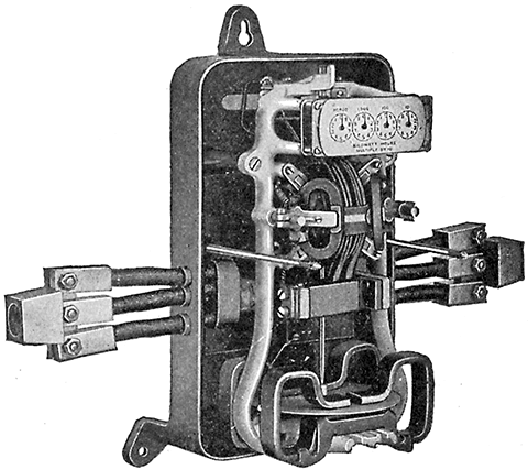
Fig. 657.--Interior view of Thompson watt hour meter (type CQ). The capacities of this type range from 50 to 400 amperes inclusive, two wire, and 50 to 200 amperes inclusive, three wire, and for voltages of from 100 to 600 volts. These meters are made with either front or back connections. In front connected meters the positions of the leading-in wires and cables are the same as in the type C-6, fig. 654, so that either type of meter may be installed in the same location.
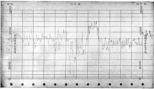
Fig. 658.--Specimen record from General Electric recording ammeter. The record is made on a band of specially prepared paper four inches wide and sixty feet in length. On this paper are ruled lines corresponding to time, and the instrument calibration. The lines ruled across the paper represent time; those ruled lengthwise represent volts, amperes, or watts, depending upon the instrument construction. This form of paper has the advantage of permitting the use of time divisions of equal length throughout the entire range of the recording pen. The recording pen is attached to the moving element in such a manner that its motion is transmitted in a straight line parallel to the time division on the chart. As the paper is unwound and passed under the recording pen, it is paid into a space at the bottom of the instrument case. To assist in removing paper, the instrument is provided with a stripper, which enables the paper to be torn off evenly and without damage. The paper feeding mechanism is simple. By means of suitable gearing, the clock drives a drum having peg teeth which engage the holes located near the edge of the paper. These teeth not only feed the paper under the recording pen, but also give it a definite and accurate position along the axis of the drum. The feeding drum is driven by a friction clutch.
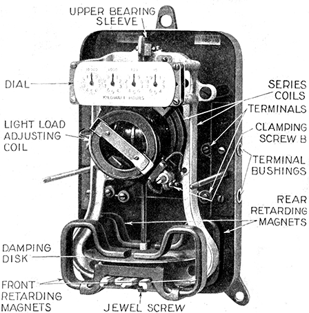
Fig. 659.--Westinghouse type CW-6 watt hour meter with cover off. This meter is of the commutator type without iron in the magnetic circuit. The spherical armature is closely surrounded by circular field coils which provide the shortest magnetic path and smallest magnetic leakage, thus securing high torque with small consumption of energy. The armature winding is wound on a hollow sphere of prepared paper which is moulded in corrugated form to secure strength. Uniform brush tension is maintained by gravity. Each brush consists of two small round wires placed side by side and held against the commutator by a small counterweight whose distance from the fulcrum is adjustable. The current winding consists of two flat coils of strap copper, one clamped rigidly on either side of the central mounting frame which supports the armature bearings. These coils are connected either in series or parallel, depending on the capacity. In three wire meters one of the coils is connected in series with each side of the line. The retarding element consists of a light aluminum disc rotating between two pairs of permanent magnets. The magnets are prepared by a special aging process to insure permanence. Full load adjustment is made by shifting the position of the permanent magnets. Ample light load adjustment or friction compensation is provided by means of the movable coil, which can be shifted horizontally or radially on loosening one screw. The meter registers directly in kilowatt hours.
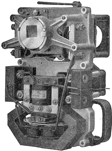
Fig. 660.--Interior of Thompson prepayment watt hour meter. The actuating force is a large flat coil spring enclosed in a barrel or drum to which its outside end is attached. The operating knob winds this main spring by turning the drum. The spring has many turns and as the operation of the device never equals one whole turn, the spring always exerts a practically constant force. The rate device consists of a small train of gears secured to the front of the frame directly back of the register. Each device is marked with the price per kw-hr. for which it should be used. The switch is of the double pole double break type with leaf contacts. The coin receptacles are placed at the back of the meter. To make an advance payment, the winding knob is turned so that the arrow points upward. A quarter dollar is then inserted in the slot and the knob turned to the right, the coin serving as a key which operates the mechanism within the device, turning the registering wheel and placing the coin to the credit of the customer. If the circuit be open when the coin is deposited the same motion of the knob which moves the registering mechanism closes the circuit switch contained within the case. The dial contains a scale marked in plain figures over which a pointer passes indicating the number of coins remaining to the credit of the depositor. When the first coin is deposited and the knob turned closing the main switch, the pointer rests opposite the first division on the scale. If a second coin be deposited before the current purchased with the first coin has been consumed, a second motion of the knob will bring the pointer opposite the second division on the scale. Twelve coins can thus be deposited consecutively, after which the slot is automatically closed and further prepayment cannot be made until the value of one or more coins has been consumed. Whenever energy to the value of one coin has been delivered through the meter, the escapement is mechanically released turning the pointer back one division. This process continues until all the energy has been delivered for which payment has been made. Thus the depositor can ascertain at any time how much energy can be obtained without further payment. When all energy has been delivered, the circuit switch is opened so that no more current can be obtained until one or more coins have been deposited. The indicating mechanism shows only the number of coins which stand to the credit of the customer, but, by consulting the meter dial, one can determine what fractional part of the prepayment next to be cancelled remains to the credit of the customer. A coin or washer larger than the coin for which the device is designed cannot be introduced into the receiving slot and a smaller one will not operate the device.
How to test a meter.--A simple test for ascertaining whether a customer's meter is fast or slowC, may be applied as follows:
Turn off the lamps and other power consuming devices in the house and then note the reading of the meter dial and the exact time of day;
Turn on as quickly as possible about one-tenth of all the lamps in the house and allow them to burn for about two hours;
At the end of two hours, turn off the lamps as quickly as possible and note the reading of the meter dial.
The difference between the first and second readings of the dial will be the indicated consumption of two hours, and if this be greater than the amount of power that ought to be consumed by the number of lamps turned on, the meter is fast, but if it be less, the meter is slow.
The best results obtained by this method are only approximations, however, on account of the variations in the watts consumed by the different makes of lamp, the uncertainty as to the actual voltage on the line at the time of the test, and the lack of knowledge as to the age of the lamps. Therefore, if the meter test within five per cent., or do not record more nor less than one-twentieth of the assumed lamp consumption it is safe to assume that the meter is correct as the result of the test is not likely to be any closer to the truth.
Ques. How should a roughened commutator be cleaned and smoothed?
Ans. By means of tape.
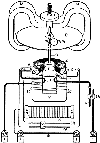
Fig. 661.--Internal connections of Sangamo watt hour meter (type D). A, copper disc armature, submerged in mercury; B, bridge wire between binding posts, for main load current, when both sides of the line are carried through the meter; CT, compounding series turns around pressure circuit magnet, building up field as load increases, to compensate for falling off in speed otherwise found; D, aluminum damping, or brake disc, controlling speed of meter; E, copper contact ears, imbedded in insulating wall of mercury chamber, leading current into and out from armature; F, hardwood float on armature proportioned to give slight "lift" to entire moving system, when armature and float are immersed in mercury; H, soft steel disc above permanent magnets, riveted to fine pitch screw working in bracket above, so that adjustment of the disc up or down gives variation in damping effect of permanent magnets, and therefore of main speed. K, clamp slider with thumb screw, for obtaining light load adjustment by moving K to right or left, as may be necessary. K spans and connects parallel wires of light load adjustment, BR and RR'. MM, powerful permanent magnets, acting on disc D, giving main speed control for meter. N, high resistance heavy wire, forming part of series adjustment between armature and any shunt with which meter may be used, to set drop through meter correct for drop of the shunt. P, spirally laminated soft steel ring, moulded in mercury chamber above the armature space, to act as a return for magnetic lines of force from and to energizing magnet below. R, resistance card unit, in series with pressure circuit coils; in 110 volt meters one card is used, in 220 volt meters two cards, or one card and a thermocouple. BR, small brass wire, connected to ingoing end of pressure circuit coils and forming RR' and the slides K the light load adjustment. RR', high resistance wire having opposite ends connected to ears EE by low resistance wires. Current energizing the pressure circuit coils SC passes from RR' through K to BR and thence to the coils, and if K be near the end of RR' and BR, the least compensation is obtained; if near right end, maximum light load compensation is obtained. S, shaft or spindle. In actual meter S is divided, the lower shaft carrying armature A, and the upper shaft damping disc D. SA, series resistance adjustment, for setting meter to correct drop for shunt. SC and SC', pressure coils connected in series. TT, binding posts at bottom of meter. Y, laminated soft steel yoke, carrying coils SC and SC', and giving a powerful and concentrated magnetic field on the armature. W, worm, driving recording dial train. WW, worm wheel.
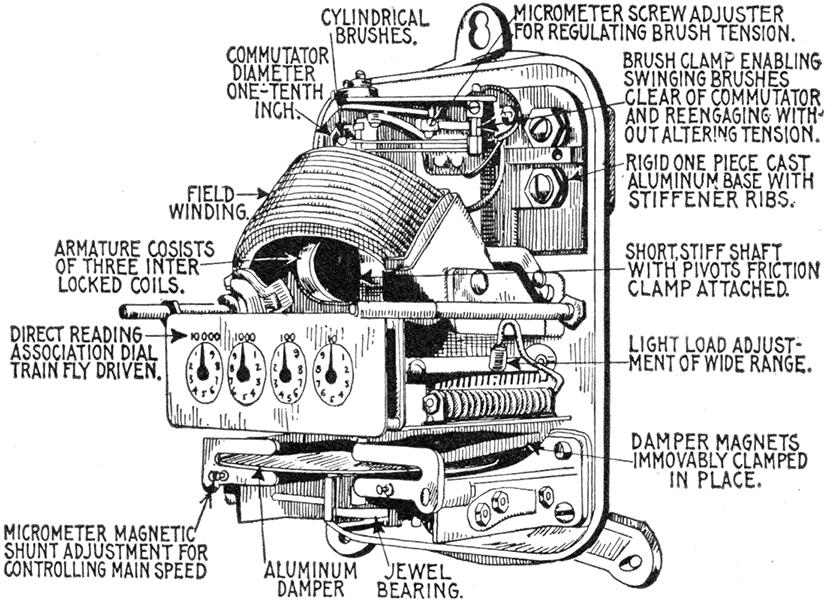
Fig. 662.--Interior view of Columbia watt hour meter (type D), showing construction and principal parts and connections. The armature winding consists of three coils approximately circular in shape. The coils are form wound, interlocked with one another and with the light impregnated fibre disc which serves as a spacer for them. The aluminum damper disc has the conventional anti-creep provision in the shape of the three small soft iron plugs, mounted close to the central staff, which the illustration shows. These in their revolution come successively within the influence of an adjustable iron screw which is magnetized by an extension from one of the damper magnets. The angular relationship of the armature windings and of the three iron plugs is such that at the time that the armature is exerting a maximum torque the magnetized screw is exerting the maximum pull to hold back a given plug and conversely when the armature pull is a minimum the magnetic screw is attracting a plug with the maximum effort to cause ahead rotation. The irregularities of torque are in this way smoothed out. The commutator has three segments and is made of chemically pure silver. Each brush is formed of a length of phosphor bronze wire bent like a hair pin and secured at its "U" end to a brass sleeve, which in turn is secured to an insulated stud by a set screw. An extension on the sleeve carries a micrometer screw brush adjustment. The main speed adjustment is secured by providing a soft iron bridge plate, bridging over the extremities of each magnet end and adjustable, by means of a set screw and lock nut, to any desired distance therefrom. This gives a regular micrometer means of varying the effective magnet strength. Interposed between the series coil and the permanent magnets is a heavy soft iron shield to guard the magnets against disturbance by short circuiting. Light load adjustment is obtained by providing in the coil circuit a series of small resistance spools, equipped with pin terminals, to which connection can be selectively made by means of a split bushing terminal on a flexible cord. This series of spools is strung on a metal arbor located within the case.
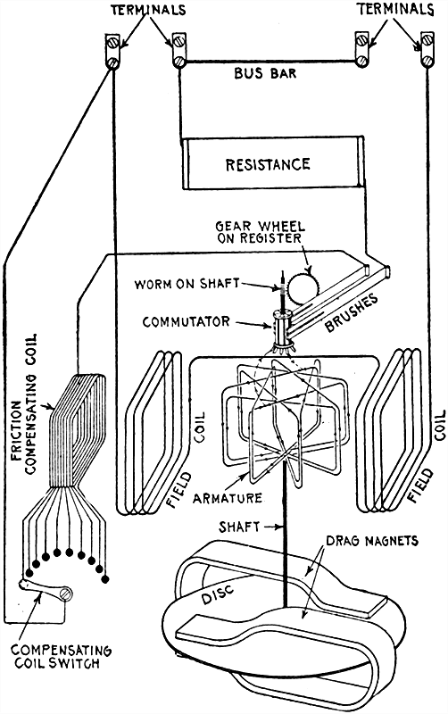
Fig. 663.--Diagram showing internal connections of the Duncan watt hour meter. Its operation depends upon the principle of the well known electro-dynamometer, in which the electromagnetic action between the currents in the field coils and an armature produces motion in the latter. It also embodies the other two necessary watt hour meter elements required for the speed control and registration of the revolutions of the armature, these being embodied in the drag magnet and disc, and the meter register respectively. The motion of the armature is converted into continuous rotation by the aid of a commutator and brushes, the commutator being connected to the armature coils and carried on the same spindle therewith.
Waste of Electricity in Lighting.--In large residences where a good many servants are employed or in any place where the power consumed is not directly under the supervision of the person who must pay the bills, a great deal of waste usually occurs.
If the meter be read before retiring, the reading in the morning will show how much energy was consumed during the night, which will show in turn how many lamps were burning all night.
A great deal of light can be saved by placing the lamps so that they will throw the light where it is needed and by placing small lamps such as 8 candle power and 4 candle power in places where not much light is needed, such as bathrooms, halls, cellars, etc.
When the lamps get old and dim they should be replaced with new ones, as it costs about the same to burn an old lamp as a new one. An old 16 candle power lamp which is very dim will give only about 8 candle power and use about as much current as is required for a new 16 candle power. If the dim light be light enough, it should be replaced by an 8 candle power lamp, which will not consume as much power as the old 16 candle power.