Chapter XXVII · TESTING AND TESTING APPARATUS
Reading edition
The practical electrician frequently has to make tests of various kinds which require the rapid and accurate measurement of voltage, current and resistance. It is therefore essential that he understand the methods employed in testing and the operation of the instruments used.
Most tests are made with a galvanometer, and the devices, such as resistances, switches, etc., which are used in connection with the galvanometer may be obtained put up in a neat and substantial box together with the galvanometer, the combination being called a "testing set." Numerous forms of testing set are illustrated in this chapter.
The construction, use, and operation of the various types of galvanometer have been explained in chapter twenty-six. Ammeters and voltmeters, which are simply special forms of galvanometer, and which are largely used are fully described in the preceding chapter.
Pressure Measurement.--An electromotive force has been defined as that which causes or tends to cause a current; it is analogous to water pressure; potential difference corresponds to difference of level. The total electromotive force of a circuit is independent of resistance or current, and cannot be limited to mean the fall of pressure between any two points, as for instance the terminals of a battery.
If the pressure of a battery be two volts when measured on open circuit by a static voltmeter, there will still be two volts on closed circuit, but there will now be a loss of pressure through the internal resistance of the battery and the voltage across the terminals will be less than the total voltage. The static voltmeter, never closing the circuit, actually measures the total voltage.
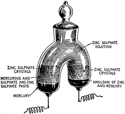
Fig. 540.--Clark cell (Kahle's modification of the Rayleigh H form), the standard for the International volt. The cell has for its positive electrode, mercury, and for its negative electrode, amalgamated zinc. The electrolyte consists of a saturated solution of zinc sulphate and mercurous sulphate. The pressure is 1.434 volts at 15°C., and between 10°C. and 25°C. the pressure decreases .00115 of a volt for each increase of 1°C. The containing glass vessel consists of two limbs, closed at bottom and joined above to a common neck fitted with a ground glass stopper. The diameter of the limbs should be at least 2 cms., and their length at least 3 cms. The neck should be not less than 1.5 cms. in diameter. At the bottom of each limb a platinum wire of about .4 mm. in diameter is sealed through the glass. To set up the cell, place mercury in one limb, and in the other hot liquid amalgam, containing 90 parts mercury and 10 parts zinc. The platinum wires at the bottom must be completely covered by the mercury and the amalgam, respectively. On the mercury, place a layer 1 cm. thick of the zinc and mercurous sulphate paste. Both this paste and the zinc amalgam must be covered with a layer of the neutral zinc sulphate crystals 1 cm. thick. The whole vessel must then be filled with the saturated zinc sulphate solution, and the stopper inserted so that it shall just touch it, leaving, however, a small bubble to guard against breakage when the temperature rises. Before finally inserting the glass stopper a strong alcoholic solution of shellac is applied to the upper edge, after which the stopper is pressed firmly in place.
Ques. What error is introduced in measuring the pressure of a battery with an ordinary voltmeter?
Ans. Since the measurement is made on closed circuit the reading does not give the total pressure of the battery.
The error is very slight because the resistance of the voltmeter is very high and the current so small that the loss of pressure in the battery can be neglected.
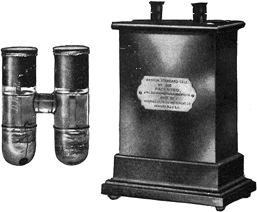
Fig. 541.--Weston Cadmium Cell. It is made in two forms; one known as the Weston normal cell, in which the solution of cadmium sulphate is saturated at all temperatures at which the cell may be used. The other, known as the Weston standard cell, in which the cadmium sulphate solution is unsaturated at all temperatures above 4°C. The Weston normal cell, or saturated form is slightly affected by changes in temperature, but, on account of the fact that it can be accurately reproduced, it was adopted by the London Conference in 1908, as a convenient voltage standard. The value of its voltage suggested by the committee of the London Conference on Electrical Units and Standards, and adopted by the Bureau of Standards at Washington, Jan. 1st, 1911, is 1.0183 International volts at 20°C. At any other temperature its voltage is:
Et = E20 - 0.0000406(t-20) - 0.00000095(t-20)2 + 0.00000001(t-20)3
The Weston standard cell, or unsaturated form is practically unaffected by changes in temperature and is the form most commonly used for laboratory work and general testing. The average pressure of this form is 1.0187 Int. volts.
Ques. Define the International volt.
Ans. It is the electromotive force that, steadily applied to a conductor whose resistance is one International ohm, will produce a current of one International ampere, and which is represented sufficiently well for practical use by 1,000/1,434 of the voltage between the poles of the Clark cell at a temperature of 15° C., when prepared as in fig. 540.
The relation between the units volt, ampere and ohm, are shown graphically in figs. 542 and 543.
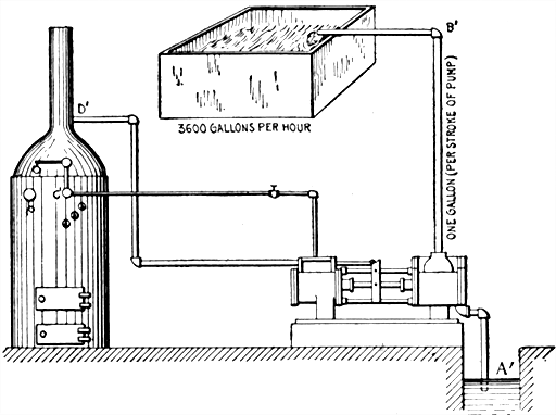
Figs. 542 and 543.--Diagrams showing hydraulic analogy illustrating the difference between amperes and coulombs. The rate of current flow of one ampere in fig. 543 may be compared to the rate of discharge of a pump as in fig. 542. Assuming the pump to be of such size that it discharges a gallon per stroke and is making 60 strokes per minute, the quantity of water discharged per hour (coulombs in fig. 543) is 1 × 60 × 60 = 3,600 gallons. Following the analogy further (in fig. 543), the pressure of one volt is required to force the electricity through the resistance of one ohm between the terminals A and B. In fig. 542, the boiler must furnish steam pressure on the pump piston to overcome the friction (resistance) offered by the pipe and raise the water from the lower level A' to the higher level B'. The difference of pressure between A and B in the electric circuit corresponds to the difference of pressure between A' and B'. The cell furnishes the energy to move the current by maintaining a difference of pressure at its terminals C and D; similarly, the boiler furnishes energy to raise the water by maintaining a difference of pressure between the steam pipe C and exhaust pipe D'.
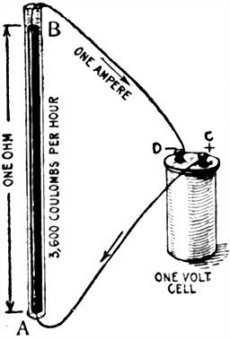
Fig. 543. If the current strength in fig. 543 be one ampere, the quantity of electricity passing any point in the circuit per hour is 1 × 60 × 60 = 3,600 coulombs.
Current Measurement.--It is necessary to adopt some arbitrary standard in order to compare currents of different strengths. The term strength of a current, or current strength means the rate of flow past any point in the circuit in a given unit of time. The unit of current, called the ampere, is defined as the unvarying current which, when passed through a solution of nitrate of silver in water (15 per cent. by weight of the nitrate) deposits silver at the rate of .001118 gramme per second.
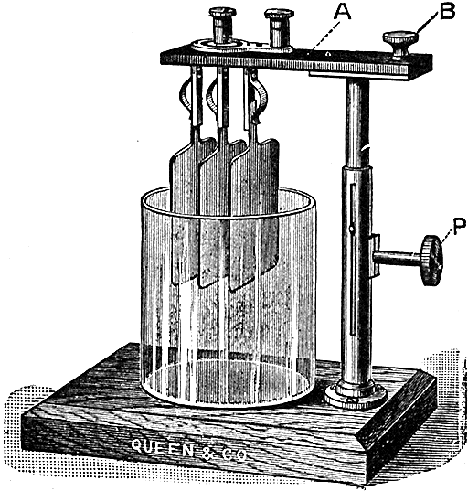
Fig. 544.--Queen weight voltameter for determining the strength of current by the weight of metal deposited in a given time. The two outside plates form the anode and are joined together and to one binding post, while the cathode is placed between them and connected to the other binding post. The cathode thus receives a deposit on both sides. An adjustable arm serves to lower the plates into the electrolyte. To calculate the strength of an unknown current which has passed through a weight voltameter, divide the gain in weight by the number of seconds the current flows through the instrument and by the weight deposited by one ampere in one second. That is, current strength in amperes = gain in weight ÷ (time in seconds × .0003286).
Ques. How much copper or zinc will one ampere deposit in one second?
Ans. .0003286 gramme of copper in a copper voltameter, or .0003386 gramme of zinc in a zinc voltameter.
Ques. What is the difference between an ampere and a coulomb?
Ans. An ampere is the unit rate of flow of the current, and a coulomb is the unit quantity of electricity, that is, the ampere is the rate of current flow that will deposit .0003286 grammes of copper in one second and a coulomb is the quantity of electricity that passes a given point in one second when the current strength is one ampere. In other words a coulomb is one ampere second.
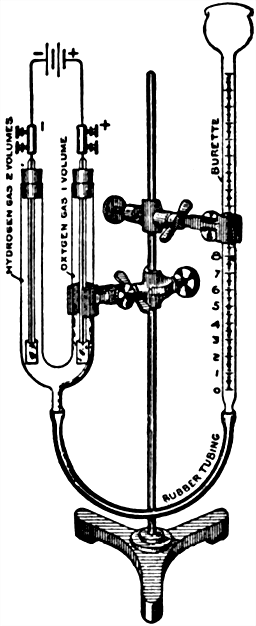
Fig. 545.--Gas voltameter for determining the strength of current by the volume of gas evolved. To use, connect up as shown in the illustration. Adjust so that the zero position of the burette is about one-half inch below the level of the top of the U tube. Pour acidulated water into the mouth of the burette till the water in the U tube is about one-half inch from the top. With the electrodes inserted through the corks, carefully place each one in position by giving a slight twist to the right as the cork enters. The water level in the U tube and burette should now be the same, or further adjustment must be made to attain this result. The level in the burette does not necessarily have to correspond with the zero graduation, but must not be below it. Unclamp the burette and hold it nearly horizontal. The liquid will not run out if the corks be tight, so that this is the air leakage test. Attach the connectors and wires from the current source (which should have a pressure of 2 or more volts) placing a switch in the circuit. When the switch is closed, bubbles of gas will rise in the U tube from both electrodes, displacing the water and forcing it up the burette. Hydrogen will be liberated over the negative electrode, and oxygen over the positive electrode in the proportion of twice as much hydrogen as oxygen. To calculate the current strength, divide the volume of gas liberated by the time in seconds, and by the volume of gas liberated (in cubic centimeters) by one ampere in one second and by .1733; that is: amperes = volume of gas liberated ÷ (time in seconds × .1733).
EXAMPLE.--If an arc lamp require a current of 8 amperes, how much electricity does it consume per hour?
Since one coulomb = one ampere second, the quantity of electricity consumed per hour is
8 amperes × ( 60 × 60 ) = 28,800 coulombs.
Voltameter.--A voltameter is an electrolytic cell employed to measure an electric current by the amount of chemical decomposition the current causes in passing through the cell. There are two classes of voltameter:
Weight voltameters;
Gas voltameters.
Ques. What is the difference between these two classes of voltameter?
Ans. In one, the current strength is determined by the weight of metal deposited or weight of water decomposed, and in the other by the volume of gas liberated.
Fig. 544 shows a weight voltameter and fig. 545 a gas voltameter.
Ques. How should the plates of a weight voltameter be treated before use?
Ans. They must be thoroughly cleaned and polished with sandpaper, the sand being afterwards removed by placing them in running water. The fingers must not be placed on any part of the plate which is to receive the deposit.
Ques. What form of voltameter has been selected to measure the International ampere?
Ans. The silver voltameter arranged as here specified:
The cathode on which the silver is to be deposited shall take the form of a platinum bowl, not less than 10 cms. in diameter, and from 4 to 5 cms. in depth.
The anode shall be a disc or plate of pure silver some 30 sq. cms. in area, and 2 or 3 cms. in thickness. This shall be supported horizontally in the liquid near the top of the solution by a silver rod riveted through its center.
To prevent the disintegrated silver which is formed on the anode falling upon the cathode, the anode shall be wrapped around with pure filter paper, secured at the back by suitable folding.
The liquid shall consist of a neutral solution of pure silver nitrate containing about 15 parts by weight of the nitrate to 85 parts of water.
Ques. What is the value of the International ampere as measured with the silver voltameter?
Ans. The International ampere is represented sufficiently well for practical use by the unvarying current which, when passed through a silver voltameter (as described above) deposits silver at the rate of .001118 gramme per second.
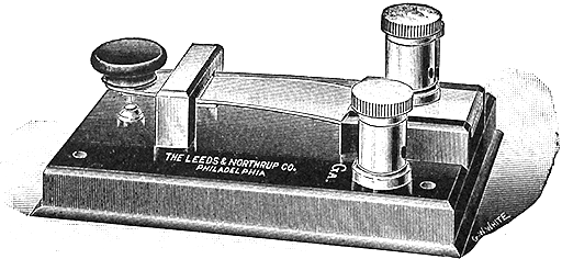
Fig. 546.--Single contact and short circuiting key. This key is intended especially for use with D'Arsonval galvanometers in zero deflection methods. The key is connected in circuit with the galvanometer so that whenever the key is not depressed, the galvanometer is short circuited, and its oscillations quickly damped out by the currents induced in its coil. The back end of the spring is held in a slot in a rubber block attached to the base.
Ohm's Law and the Ohm.--The various tests here described depend for their truth upon the definite relation existing between the electric current, its pressure, and the resistance which the circuit offers to its flow. This relation was fully investigated by Ohm in 1827. Using the same conductor, he proved not only that the current varies with the pressure, but that it varies in direct proportion.
Ohm's law has already been discussed in a previous chapter and the several ways of expressing it are repeated here for convenience:
1. Amperes = voltsohms ;
2. Volts = amperes × ohms ;
3. Ohms = voltsamperes .
Various values have been assigned, from time to time, to the ohm or unit of resistance, the unit in use at the present time being known as the International ohm. This was recommended at the meeting of the British Association in 1892, was adopted by the International Electrical Congress held in Chicago in 1893, and was legalized for use in the United States by act of Congress in 1894. The International ohm in graphically defined in fig. 548. The previous values given to the ohm which were more or less generally accepted are as follows:
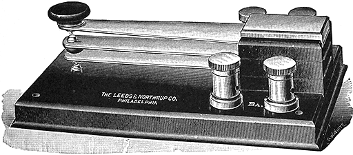
Fig. 547.--Double contact key. It is of especial value in connection with a Wheatstone bridge. When used with the latter it forms a combination battery and galvanometer key. The battery is wired to the top leaves of the key and the galvanometer to the lower leaves. Hence, when operated, the battery circuit will be closed before the galvanometer circuit, as it is desirable to avoid undue disturbance of the needle.
The Siemens' Ohm.--A resistance due to a column of mercury 100 cm. long and 1 sq. mm. in cross section at 0° C.
B. A. (British Association) Ohm.--A resistance due to a column of mercury approximately 104.9 cm. long and 1 sq. mm. in cross section at 0° C.
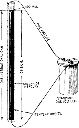
Fig. 548.--The international ohm. It is defined as the resistance of 14.452 grammes of mercury in the form of a column of uniform cross section 106.3 centimeters in length, at a temperature of 0° C. This is approximately equivalent to a column 106.3 cm. long, having a uniform cross section of 1 sq. mm. In the figure the international ohm is defined graphically. The resistance of the external circuit and the standard one volt cell is assumed to be zero.
Legal Ohm.--A resistance due to a column of mercury 106 cm. long and 1 sq. mm. in cross section at 0° C. This unit was adopted by the Paris conference of 1884.
OHM TABLEA
Date International Ohm Legal Ohm B. A. Ohm Siemens' Ohm
International Ohm 1893-4 1.0000 1.0028 1.0136 1.0630
Legal Ohm 1884 .9972 1.0000 1.0107 1.0600
B. A. Ohm 1864 .9866 .9894 1.0000 1.0488
Siemens' Ohm .9407 .9434 .9535 1.0000
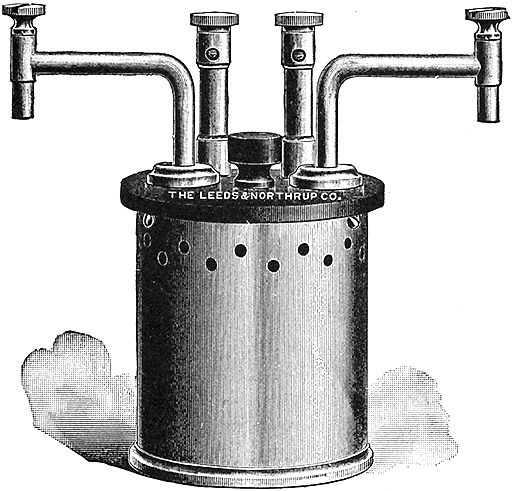
Fig. 549.--Leeds and Northrup one ohm standard resistance (Reichsanstalt form); adjusted at 20° C. Low resistance standards may be properly divided into two classes: 1. those which are designed primarily as resistance standards, and 2. those designed as current carrying standards. Those of the first mentioned class are often used to measure currents up to their capacity. The above standard has both pressure and current terminals. The binding posts for the former are mounted on high posts so as to be easily accessible when the standard is immersed in oil. When used as a resistance standard of precision, it should not be subjected to a current of more than one ampere, and when used as a current carrying standard of lesser accuracy, a current of 2 or 3 amperes may be used.
Practical Standards of Resistance.--The column of mercury as shown in fig. 548, is the recognized standard for resistance, however, in practice, it is not convenient to compare resistances with such a piece of apparatus, and therefore secondary standards are made up and standardized with a great degree of precision. These secondary standards are made of wire. The material generally used being manganin or platinoid.
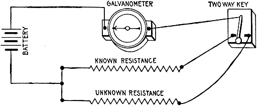
Fig. 550.--Direct deflection method of testing resistances; a useful and simple method which may be used in numerous tests. Galvanometer readings are taken through the known, and unknown resistances, and the current being proportional to the deflections, the value of the unknown resistance is easily calculated.
Resistance Measurement.--Resistance is that which offers opposition to the flow of electricity. Ohm's law shows that the strength of the current falls off in proportion as the resistance in the circuit increases. This gives a basis for measuring resistance.
There are various methods by which an unknown resistance may be measured, as by the:
Direct deflection method;
Method of substitution;
Fall of potential method;
Differential galvanometer method;
Drop method;
Voltmeter method;
Wheatstone bridge method.
Direct Deflection Method.--This method is based on the fact that the greater the current through a galvanometer the greater the deflection of the needle; it is a simple method and is capable of extended application.
The apparatus required consists of battery, galvanometer, known resistance, and double contact key. The connections are made as in fig. 550. The known resistance is put in circuit with the galvanometer and after noting the deflection, the key is moved so as to cut out the known resistance and throw into circuit the unknown resistance. The deflection of the galvanometer is again noted and compared with the first deflection.
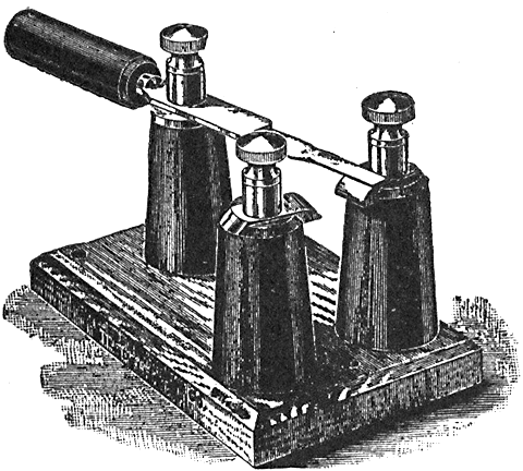
Fig. 551.--Charge and discharge key, adapted to condenser testing where the condenser is to be alternately charged and discharged. The insulated handle enables the key to be used without insulating the body.
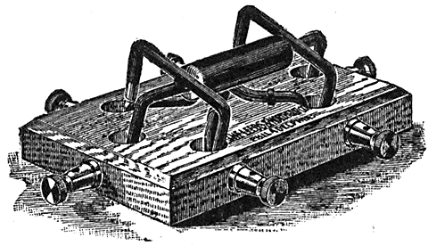
Fig. 552.--Pohl commutator. This is equivalent to a two pole double throw switch. The depressions in the base are filled with mercury into which the contacts dip in closing the circuit.
If the deflections be proportional to the current, the unknown resistance will be as many times the known resistance as the deflection with the known resistance is greater than the deflection with the unknown resistance.
Method of Substitution.--This is the simplest method of measuring resistance. The resistance to be measured is inserted in series with a galvanometer and some constant source of current, and the galvanometer deflection noted. A known adjustable resistance is then substituted for the unknown and adjusted till the same deflection is again obtained. The value of the adjustable resistance thus obtained is equal to that of the resistance being tested.
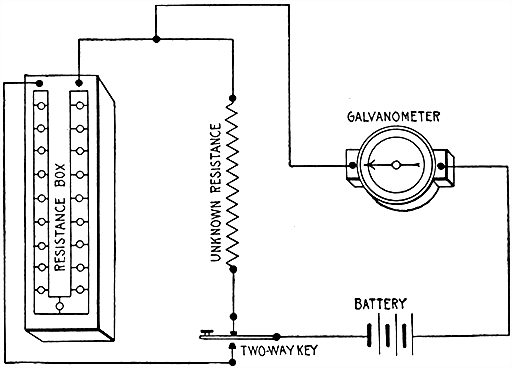
Fig. 553.--Substitution method of testing resistances. The connections and apparatus are the same as in fig. 550, except that a resistance box is used in place of the known resistance. In making the test, first note deflection with unknown resistance in circuit, then press key so that the current will pass through the resistance box, and adjust the resistance in the box so that the deflection of the galvanometer is about the same as with the unknown. Now switch from one circuit to the other, changing the resistance in the box until equal deflections are obtained. When this obtains, the resistance in the box is the same as the resistance being tested.
Ques. What kind of adjustable resistance is used in making the above test?
Ans. A resistance box.
Ques. Describe a resistance box.
Ans. It consists of a box containing numerous resistance coils with their ends connected to terminals and provided with plugs so that they may be thrown into or out of circuit at will, thus varying the resistance in the circuit.
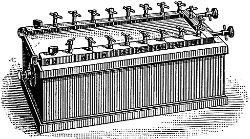
Fig. 554.--Ordinary resistance box. It contains sets of standard resistances consisting of coils of insulated wire having low conductivity and small temperature coefficient. The ends of the coils are joined to the section of the bar between the plugs. The insertion of a plug cuts out a coil. In using, care should be taken to put the plugs in with a slight twist so that there shall be no resistance introduced by poor contact.
Fall of Potential Method.--This is a very simple method of measuring resistances, and one that is convenient for practical work in electrical stations because it requires only an ammeter, voltmeter, battery and switch--apparatus to be found in every station. The connections are made as shown in fig. 555.
In making the test the ammeter and voltmeter readings are taken at the same time, and the unknown resistance calculated from Ohm's law. Accordingly, since:
(1) amperes = volts / ohms
solving for the resistance,
(2) ohms = volts / amperes
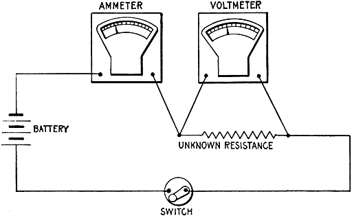
Fig. 555.--Fall of potential method of testing resistances; a convenient method for testing at stations, requiring only the usual instruments to be found at a station. The resistance of the voltmeter must be very high, otherwise the test must be made as in fig. 556.
EXAMPLE.--If in fig. 555 the readings show 6 volts and 2 amperes how many ohms is the resistance being tested?
Substituting in formula (2)
ohms = 6/2 = 3
Ques. Can this test be made with any kind of voltmeter?
Ans. Its resistance must be very high to avoid error. When a voltmeter having small resistance is used, it should be connected so as to measure the fall of pressure across both ammeter and unknown resistance as shown in fig. 556.
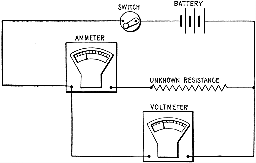
Fig. 556.--Fall of potential method of testing resistances; diagram showing connections for testing with low resistance voltmeter. The resistance measured with this connection will be the sum of the resistances of the coil and the ammeter. The resistance of the ammeter is usually known and can be subtracted from the sum to obtain the required resistance.
Differential Galvanometer Method.--This is what is known as a nil or zero method, that is, a method of making electrical measurements in which comparison is made between two quantities by reducing one to equality with the other, the absence of deflection from zero of the instrument scale showing that the equality has been obtained.
The test is made with a differential galvanometer, and resistance box connected as in fig. 557. The current then will divide so that part of it flows through the resistance being tested and around one set of coils of the galvanometer while the other part will flow through the resistance box and the other set of coils as indicated. When the resistance box has been so adjusted that its resistance is the same as the unknown resistance the current in the two branches will be equal, and the needle of the galvanometer will show no deflection.
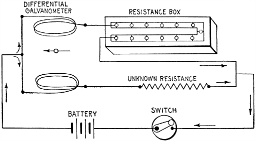
Fig. 557.--Differential galvanometer method of testing resistances. In making the test, the resistance box is adjusted till the galvanometer needle shows no deflection. When this condition obtains, the resistance in circuit in the resistance box is equal to the unknown resistance, hence, a reading of the box gives the value of the unknown resistance.
Ques. What name is given to this method of testing?
Ans. It is called a zero method, distinguishing it from deflection methods.
Ques. For what kind of resistance is the method adapted?
Ans. Since it is a nil or zero method, it is better adapted to the measurement of non-inductive than of inductive resistances.
Ques. What precaution should be taken with inductive resistances?
Ans. The current must be allowed to flow until it becomes steady to overcome the influence of self-induction.
Ques. What may be said with respect to the differential galvanometer method?
Ans. With an accurate instrument it is very reliable.
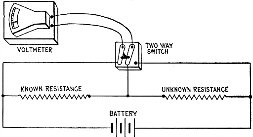
Fig. 558.--Drop method of testing resistances. The apparatus is connected as shown and readings taken with voltmeter across known and unknown resistance. The unknown resistance is then easily calculated.
Drop Method.--This is a convenient method, and one which may be used for measuring either high or low resistances with precision. It is used for many practical measurements, and requires only a voltmeter, battery, known resistance and a two way switch.
The instruments are connected as in fig. 558, and in making the test, the voltmeter is switched into circuit across the known resistance and then across the unknown resistance, readings being taken in each case. The value of the unknown resistance, is then easily calculated from the following proportion:
drop across known resistancedrop across unknown resistance = known resistanceunknown resistance
from which
unknown resistance = known resistance × drop across unknown resistancedrop across known resistance
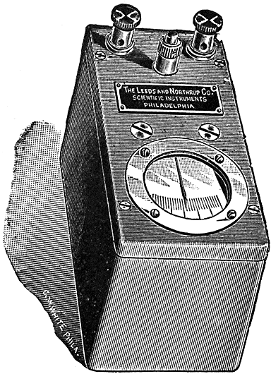
Fig. 559.--Leeds and Northrup portable galvanometer (pointer type A). The sensitiveness of this instrument is such that it may be substituted in numerous cases for the non-portable reflecting type of galvanometer; as for instance, in the checking of ammeters and voltmeters to an accuracy of .2% by the potentiometer method, and on almost all Wheatstone bridge measurements to commercial accuracies. A current of 2 micro-amperes will cause the pointer to move 1 mm. over the scale, that is, it has a sensibility of 500,000 ohms. The method of suspending the moving system is such as to practically eliminate initial friction which is of value in all zero deflecting methods. The suspensions and moving system are guarded by springs, which together with the solid construction of the case render the instrument capable of withstanding rough usage. Overall dimensions are 5-1/4" x 2-5/8" x 3-1/2"; weight about 3 pounds.
Ques. What may be substituted for the voltmeter?
Ans. A high resistance galvanometer, whose deflections are proportional to the current, the value of the deflections being substituted in the formula.
Ques. What precaution should be taken in making the test?
Ans. The current used should not be strong enough to appreciably heat the resistance, and if the current be not very steady, several readings should be taken of each measurement and the average values used in the formula.
Ques. How are the most accurate results obtained?
Ans. By selecting the known resistance as near as possible to the supposed value of the unknown resistance.
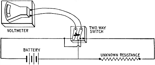
Fig. 560.--Voltmeter method of testing resistances. Knowing the resistance of the voltmeter, turn switch to the left and from reading calculate resistance corresponding to one division of the scale. Turn switch to right and multiply reading by resistance required for deflection of one division. This gives resistance of voltmeter and unknown resistance; subtracting from this the resistance of voltmeter gives value of the unknown resistance.
Voltmeter Method.--This is a direct deflection method and consists in determining first the resistance that will deflect the needle through one division of the scale on a given battery current, then with this as a basis for comparison the voltmeter is connected across the unknown resistance whose value is easily calculated from the reading.
In making the test, the instruments are connected as in fig. 560. The current from battery is first passed through the galvanometer by turning switch as shown.
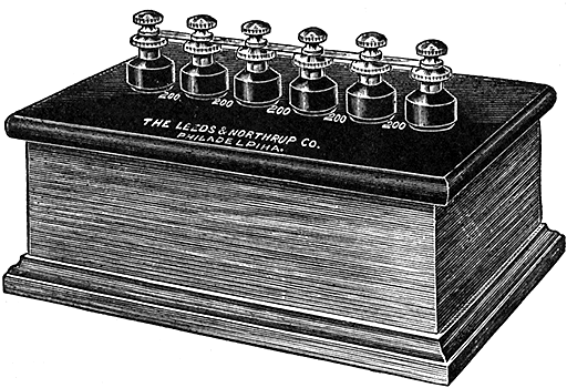
Fig. 561.--Megohm box or set of standard high resistances. The box contains five resistances of 200,000 ohms each. The six pillars are petticoat insulated, the resistances being placed between each pair of pillars. There is a double contact post on top of each pillar so that these can be connected together with copper links.
Assuming that the resistance of the instrument is 8,000 ohms and that the current deflects the needle through 10 divisions of the scale, then for a deflection of one division the resistance is
8,000 × 10 = 80,000 ohms.
Accordingly, if, when the switch is moved to the right, connecting the voltmeter across the unknown resistance, the needle be moved through 6 divisions of the scale, the combined resistance of the voltmeter and unknown resistance is
80,000 ÷ 6 = 13,333-1/3 ohms,
and subtracting the resistance of the voltmeter, the value of the unknown resistance is
13,333-1/3 - 8,000 = 5,333-1/3 ohms.
Ques. For what kinds of test is the voltmeter method best adapted?
Ans. For measuring high resistances, as the insulation of wires, etc.
Ques. What may be said with respect to the current used?
Ans. Its voltage should be as high as possible within the limits of the voltmeter scale.
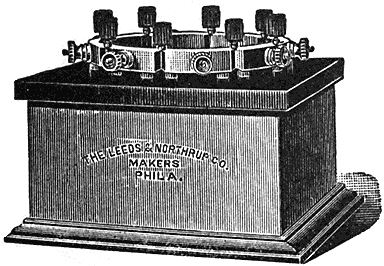
Fig. 563.--Standard resistance box: 100,000 ohms, in four units of 10,000, 20,000, 30,000, and 40,000 ohms. An "infinity" plug separates each coil from the ones adjacent. Segments are elevated from the hard rubber top by special washers in order to increase insulation. Binding posts are so arranged as not to be in the way when plugs are used.
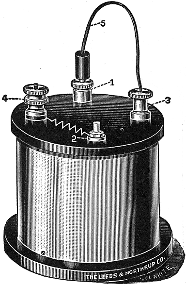
Fig. 562.--Standard high resistance box: 100,000 ohms. It is mounted in a brass box with a hard rubber top. Connections should be made to terminals marked 3 and 4. When the flexible cord is on plug 1, the box is short circuited, but when on plug 2, the resistance of 100,000 ohms is in series. The box is especially suited to rapid cable testing.
Ques. In testing cable insulation what is desirable with respect to voltmeter and current?
Ans. A low reading voltmeter should be used in connection with a large battery.
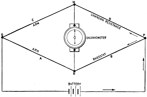
Fig. 564.--Diagram showing principle of Wheatstone's bridge. A, B, C, and D, are the four members which constitute the bridge. The current from the battery divides at P, part traversing DC, and part traversing BA. The galvanometer connected to M and N will indicate when the currents are equal in the two branches by giving no deflection. This is then a zero or nil method of testing. The resistances and keys required in testing are shown in fig. 565. In the actual instrument, the members A, B, C, and D are known by the names given in the figure.
Wheatstone Bridge Method.--For accurate measurements of resistance this method is almost universally used. The so-called "Wheatstone" bridge was invented by Christie, and improperly credited to Wheatstone, who simply applied Christie's invention to the measurement of resistances.
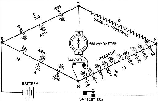
Fig. 565.--Diagram showing arms of Wheatstone bridge, resistances and method of connecting galvanometer, battery and unknown resistance.
The bridge consists of a system of conductors as shown in fig. 564. The circuit of a constant battery is made to branch at P into two parts, which re-unite at Q, so that part of the current flows through the point M, the other part through the point N. The four conductors A, B, C, D, are spoken of as the arms of the balance or bridge. It is by the proportion existing between the resistances of these arms that the resistance of one of them can be calculated when the resistances of the other three are known. When the current which starts from the battery arrives at P, the pressure will have fallen to a certain value. The pressure in the upper branch falls again to M, and continues to fall to Q. The pressure of the lower branch falls to N, and again falls till it reaches the value at Q. Now if N be the same proportionate distance along the resistances between P and Q, as M is along the resistances of the upper line between P and Q, the pressure will have fallen at N to the same value as it has fallen to at M; or, in other words, if the ratio of the resistance C to the resistance D be equal to the ratio between the resistance A and the resistance B, then M and N will be at equal pressures. To find out if this condition obtain, a sensitive galvanometer is placed in a branch wire between M and N which will show no deflection when M and N are at equal pressure or when the four resistances of the arms "balance" one another by being in proportion, thus:
(1) A:C = B:D
If, then, the value of A, B, and C be known, D can be calculated. The proportion (1) is reduced to the following equation before substituting.
D = BC/A
For instance, if A and C be, as in fig. 565, 10 ohms and 100 ohms respectively, and B be 15 ohms, D will be (15 × 100) ÷ 10 = 150 ohms.
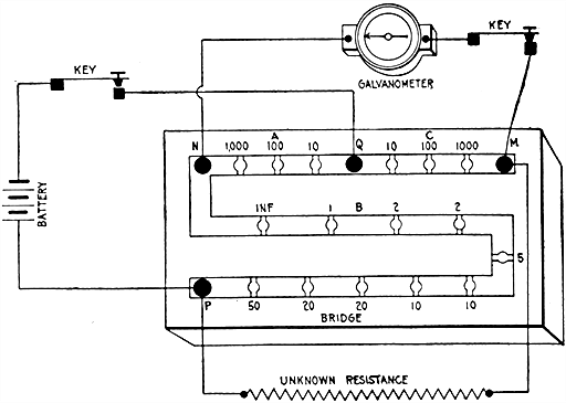
Fig. 566.--Diagram showing usual arrangement of resistances in arms of Wheatstone's bridge. In practice the bridge is seldom or never made in the lozenge shape of the diagrams, figs. 564 and 565, these being given merely for clearness. The resistance box of fig. 554 is, in itself, a complete "bridge," the appropriate connections being made by screws at various points. The letters in the above diagram correspond with those in figs. 564 and 565, and the three figures should be carefully compared.
As constructed, Wheatstone bridges are provided with some resistance coils in the arms A and C, as well as with a complete set in the arm B. The advantage of this arrangement is that by adjusting A and C, the proportionality between B and D can be determined, and can, in certain cases, be measured to fractions of an ohm. In fig. 565 resistances of 10, 100, and 1,000 ohms are included in the arms A and C.
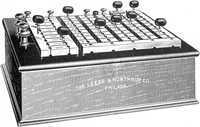
Fig. 567.--Standard resistance box and Wheatstone bridge. This pattern is a modification of the Anthony form of bridge. All the resistances are wound upon metal spools. The bridge ratio coils are 1, 10, 100, 1,000, 10,000. The rheostat coils are arranged in five rows, of ten coils each. The ordinary decade plan (explained in fig. 570) is followed. The coils may be joined in series in multiple, or in any combination of series and multiple. The coils may thus be checked against each other in many combinations. For instance, all the ten ohm coils taken in parallel may be compared with any one ohm coil. The precision of adjustment is said to be 1/20th of 1% for the coils of the tenth ohm series, and 1/50th of 1% for the coils of the rheostat. The ratio coils are certified to be like each other to within 1/100th of 1%. The box is supplied with battery and galvanometer keys of substantial construction.
Ques. Describe the method of testing with the bridge.
Ans. Fig. 567 illustrates the general arrangement of resistances to be found in an ordinary bridge. The connections are made as shown. In testing, first depress the battery key, then tap the galvanometer key. This should be repeated adjusting the resistances till no deflection is obtained. The resistance then in the arm B × (C ÷ A) will give the value of the unknown resistance.
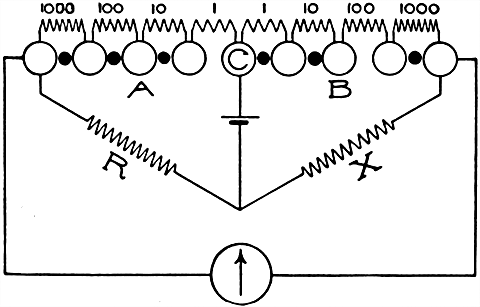
Fig. 568.--Ratio coils of Wheatstone bridge. Almost every box intended to serve as a Wheatstone bridge is furnished with a set of coils which forms the arms of proportion or ratio arms of the bridge. There is a choice of several different ways of arranging these coils. The figure shows the simplest arrangement, which is employed in boxes not intended for the highest accuracy. The required ratio, as for instance 1:100, is obtained by withdrawing a plug from each arm A and B. Ratios 1/1, 1/10, 1/100, 10/100, etc., or 1,000/1, 1,000/10, 1,000/100, 100/100, etc., are obtainable in this manner. This simple arrangement is open not only to the objection that the contact resistance of the plugs which remain in is always included with the resistance unplugged, but also to all other objections to be urged against the use of many plugs where a few will do. The method has the limitation that it is not possible to reverse the arms of the bridge, that is, to transpose the arms A and B.
Ques. Why should the battery key be depressed before the galvanometer key?
Ans. To avoid the sudden swing of the galvanometer needle, which occurs on closing circuit in consequence of self-induction.
Ques. How is it known whether too much or too little resistance be unplugged?
Ans. The galvanometer needle will be deflected to one side for too much resistance, and to the opposite side for too little resistance.
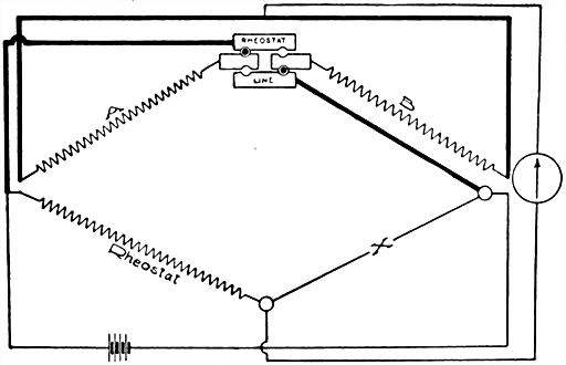
Fig. 569.--Method of reversing arms of Wheatstone bridge with reversing blocks. The arrangement shown in the figure is classical, being that used in the English post office type of Wheatstone bridge. It is open to the objections which apply to the use of several plugs, one of which is withdrawn to obtain the desired resistance.
Ques. What is the meaning of "Inf.," marked on the bridge?
Ans. It stands for "infinity," because the resistance coil at the point marked infinity is omitted so that adjacent sections of the arm are disconnected when the plug is taken out.
In fact, the air gap interposed by the removal of the plug by no means provides an infinitely great resistance, but is usually called such because it is vastly greater than any of the other resistances of the bridge.
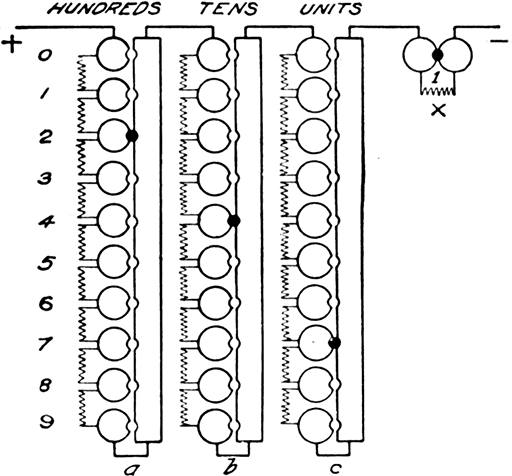
Fig. 570.
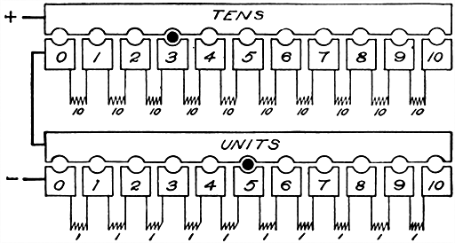
Figs. 570 and 571.--Diagrams illustrating the decade plan of combining resistance coils. In this method the coils are connected in series and the arrangement avoids the disadvantage of the ordinary Wheatstone bridge in that the latter requires a large number of plugs to short circuit the resistances not in use, which introduces an element of uncertainty as to resistance of the plug contacts and the necessity of adding up the values of all the unplugged resistances in order to determine the total resistance in circuit. The necessary regular succession of values in a rheostat built on the decade plan can be obtained with either nine or ten coils per decade. The chief reason for using the latter number is found in the facility with which all the coils of one decade can be compared with one coil of the next higher decade, thus permitting the coils of a rheostat to be checked among themselves. Thus, the ten 1 ohm coils can be checked with a 10 ohm, the ten 10's with a 100, etc. In some sets the ten coils of a decade can be connected in series or in parallel, and it then becomes an advantage to have ten coils to a decade, since the coils in one decade in parallel equal one of the coils of the next lower decade. When these latter advantages are not required, and especially when dials or sliding switches are used, there is little or no advantage in using more than nine coils per decade, as shown in fig. 570. Here all the coils of the set are connected in series so that the circuit is never open. Thus it is a slight advantage to have permanent connections a, b, and c, because all the coils of a decade can be thrown in circuit by simply pulling out a plug, it not being necessary to insert it again, as would be the case if the a, b, and c connections were not used. Moreover, if any plug make bad contact, its effect is somewhat lessened by having this bad contact shunted by the remaining coils of the decade. Again, there are occasions where violent deflections of a galvanometer are prevented by not having the circuit entirely open when a plug is taken out.
The Decade Plan.--In this method of combining resistance coils, there are 9 or 10 one ohm coils for the units place, 9 or 10 ten ohm coils for the tens place, 9 or 10 one hundred ohm coils for the hundreds place and so on. Each series of coils of the same value is designated a decade. The connections are usually made as shown in figs. 570 and 571.
It is apparent from the figure that any value in any one decade can be obtained by inserting between a bar and a block, only one plug; moreover if several decades be in series, any value up to the limit of the set can be read off directly from the position of the plugs without having to add up the unplugged resistance as in the ordinary arrangement.
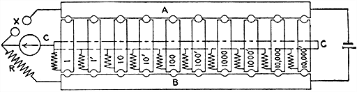
Fig. 572.--Two plug arrangement of ratio coils. Each of the ratio coils has one of its terminals connected to a common center which corresponds to the block marked C in the figure. The other terminal of each coil is connected to an individual block, there being one block for each coil. The bar B on one side of these blocks is joined to the rheostat and the bar A on the other side to an X post. In the ordinary use of this set of ratio coils two plugs only are used. One plug is inserted between the bar A and one of the blocks, 1, 1', 10, 10', etc., of the central row of blocks. The other plug is inserted between the bar B and any one of the other blocks of the central row. There are two ratio coils of each value. To obtain an even ratio as 1,000 to 1,000', one plug is inserted between the block 1,000 and the bar A, and the other plug between the 1,000 block and bar B, the ratio arms are reversed; that is, the 1,000 ohm coil is connected to the X post and the 1,000 ohm coil to the end of the rheostat. When uneven ratios are used, the same ratio can be obtained by four different combinations. To obtain the ratio one to ten, insert a plug between A and 1, and another between B and 10, or between A and 1', and B and 10, and get 1:10, or between A and 1, and B and 10', and get 1:10', or again, between A and 1' and B and 10', and get 1' to 10'. Other ratios are obtained in a similar manner. By using more than two plugs and connecting certain of the coils in parallel combinations, a large number of other ratios may be obtained. This arrangement offers a convenient method of measuring the sensibility of a bridge and galvanometer combination that is frequently applicable. If for instance the one ohm coil is used on either side after a balance has been obtained the one ohm may be shunted with the 1,000 ohm on the same side. This will make a variation of 1/10 of 1% and the galvanometer deflection may be noted for this variation. Similarly, the 1 ohm may be shunted with the 100 for a variation of 1%, or with the 10,000 for a variation of 1/100 of 1%. The ten ohm coil may be shunted with the 1,000 for a variation of 1% and with the 10,000 for a variation of 1/10 of 1%. In the arrangement of ratio coils, errors due to plug contacts are negligible because only two plug contacts enter the circuit, and with an even ratio, it is only the difference in the resistances of the two plug contacts that can affect the result. In measuring any of the ratio coils while in the box it is only necessary to connect to the bar C and to either the bar A or B and plug in the coils to be measured.
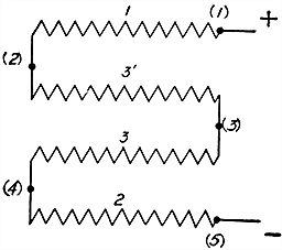
Fig. 573.
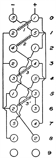
Figs. 573 and 574.--The Leeds and Northrup decade. The object of this arrangement is to reduce the number of coils required. In fig. 573, the 1, 3', 3 and 2 are connected in series. Let the terminals of the 1 ohm and 2 ohm coils be numbered (1), (2), (3), (4) and (5) (fig. 573). The current enters at point (1) and leaves the coils at the point (5), traversing 1, 3', 3, 2 = 9 ohms in all. If this series be multiplied by any factor n, then n (1 + 3' + 3 + 2) = n 9 ohms. It will be seen that if the points (1) and (5) be connected, all the coils are short circuited, and the current will traverse zero resistance. If the points (2) and (5) be connected, the 3', 3 and 2 ohm coils will be short circuited and the current will traverse 1 ohm. By extending the process so as to connect two and only two points at a time it is possible to obtain the regular succession of values n (0, 1, 2, 3, 4, 5, 6, 7, 8, 9), the last being obtained when no points are connected. Fig. 574 shows Leeds and Northrup's method of connecting these points two at a time with the use of a single plug. The circles in the diagram represent two rows of ten brass blocks each. To the first two blocks at the top of the rows, the points (5) and (1), fig. 573, are connected; to the second two, the points (2) and (5) are connected, etc., no points being connected to the last pair of blocks. Hence, if a plug be inserted between blocks 1 and 5, fig. 575, the points (1) and (5) of diagram fig. 573 are connected, giving the value of 0, if between the blocks 2 and 5 the points (2) and (5) are connected, giving the value 1, and so on. The value 9 is obtainable when the plug is in the last pair of blocks, which have no connections. Fig. 572 shows a top view of the blocks of a simple decade constructed upon this plan.
Ques. What other advantages are gained with the decade arrangement?
Ans. The single plug used with each decade is never out of use, being either in the zero position or set on some value, and is therefore not easily lost by being laid aside. The use of only one plug in a decade makes it easy to ascertain that the plug is making good contact as only one block in a row is plugged at a time, the other blocks are not kept under a strain by having plugs forced tightly between them.
This strain on the blocks, which always exists in those sets in which a resistance is thrown in by removing a plug, tends to separate or loosen them and often to warp the hard rubber upon which they are mounted. Another advantage of the decade plan is that it permits obtaining a succession of values by means of sliding contacts or dial switches, a method which is becoming deservedly more appreciated.
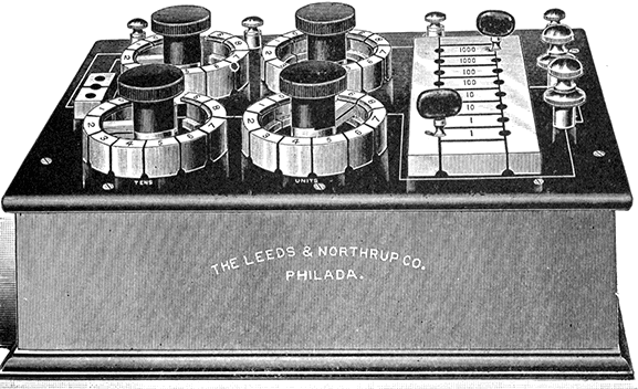
Fig. 575.--Leeds and Northrup dial Wheatstone bridge. Rotating switches are used instead of plugs, which permits quicker adjustment of the resistances, adapting it to rapid working. The ratio coils are arranged as in fig. 568. There are four dials which form the rheostat. The units dial contains 9 one ohm coils; the tens dial, 9 ten ohm coils; the hundreds dial, 9 one hundred ohm coils, and the thousands dial 9 one thousand ohm coils. The values of the ratio coils are 1, 1, 10, 10, 100, 100, 1,000, 1,000, 10,000, 10,000.
Ques. What is the difference between "plug out" and "plug in" types of resistance box?
Ans. In the plug out type, resistance is put in the circuit by removing plugs, as in fig. 565; in the plug in type, resistance is put in the circuit by inserting plugs as in figs. 570 and 571.
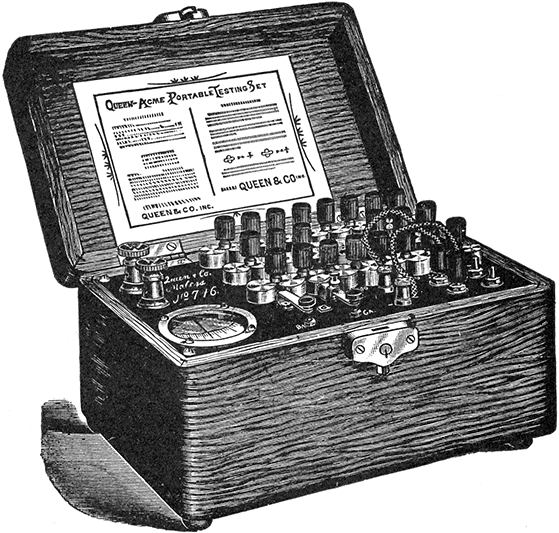
Fig. 576.--Queen Acme portable testing set. It consists of a Wheatstone bridge, with reversible arms, battery of four dry cells, D'Arsonval galvanometer, battery and galvanometer keys. There are sixteen resistance coils, having a combined resistance of 11,110 ohms. Each bridge arm is provided with three coils of 1, 10, 100 ohms, and 10, 100, 1,000 ohms respectively. The commutator admits of a ratio of 1 to 1,000 on either bridge arm, giving the set a theoretical range from .001 of an ohm to 11,110,000 ohms. For resistances above 1,000,000 ohms, the normal battery power must be increased. The contact keys are located as shown. The battery key has single contact, but the galvanometer key has double contact; depressing it closes the galvanometer circuit, and releasing it short circuits the galvanometer, bringing the latter quickly to rest.
Testing Sets.--For convenience in testing, a combination of the instruments used is put up in a neat and substantial case, and known as a testing set. There are innumerable forms of testing set, a few of which are shown in the accompanying illustrations. The usual combination is a Wheatstone bridge, galvanometer, battery and necessary keys and connections.
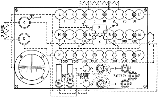
Fig. 577.--Connections and circuits of Queen acme portable testing set. There are three rows of blocks, LL', MM', NN'. LL is connected to NN' by means of a heavy copper bar, joining L' and N'. LL' and NN' constitute the rheostat, from which any resistance from 1 ohm to 11,110 ohms may be obtained by removing the proper plugs. The block N of the rheostat is connected to the lower line post D. The upper line post C is connected to the block X of the commutator. The block C has no other permanent connection, except key G. The block R of the commutator is connected to the block L of the rheostat, and has no other connection, excepting by plugs. Each half of MM' constitutes a bridge arm, designated A and B respectively. Beginning at the lower line post D, the connections form a continuous circuit through the rheostat, thence through the bridge arm B, thence through the bridge arm A, thence to the upper line post C. The commutator serves merely to reverse the bridge arms A and B. The battery terminals are connected as shown: the positive terminal directly to the common junction of the two bridge arms, and the negative terminal through the battery key to the rheostat. The positive terminal of the galvanometer is connected through the galvanometer key with the block X, and the negative terminal with the block R of the commutator or what is equivalent, with the block L of the rheostat. The commutator blocks A, B, R and X, are connected by plugs as shown. When the commutator plugs are in the position PQ, the bridge arm B is connected to the rheostat and the bridge arm A is connected to the line, the ratio between the bridge arms ratio being A ÷ B = X ÷ R but when the plugs are in the position ST, the bridge arms are reversed in position A, being connected with the rheostat and B, with the line, and the bridge arm ratio becomes A ÷ B = R ÷ X. The connections of the testing set may be more readily understood from the simplified diagram fig. 578.
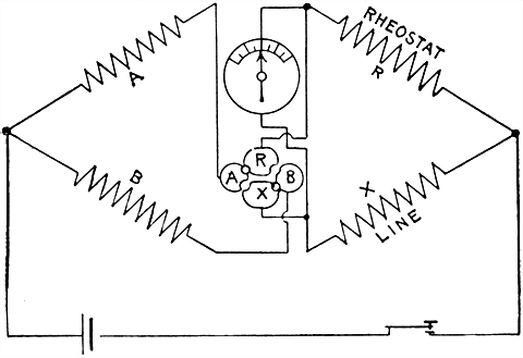
Fig. 578.--Simplified diagram showing connections of Queen Acme portable testing set.
Ques. Describe the operation of the Queen Acme testing set figs. 576 and 577, in measuring resistance.
Ans. Connect the terminals of the resistance to be measured to the line posts C and D. Place the battery connections on the two upper tips 0 and 1, thus throwing one end of the battery into circuit, which is sufficient until an approximate balance is obtained. Employ the 100 ohm coil in each bridge arm, and place the commutator plugs in the position PQ, or in the position ST. Then remove plugs from the rheostat until the value of total resistance employed, or nearly as may be guessed is equal to that of the unknown resistance. Now press the battery key Ba, and holding it down momentarily, press the galvanometer key Ga. If the galvanometer needle swing to the right toward the symbol + the resistance employed in the rheostat is too high and must be reduced. If the needle swing to the left toward -, the resistance employed is too low and must be increased. By altering the resistance of the rheostat accordingly, a value will soon be found, which when varied slightly either way, will reverse the deflection of the galvanometer needle. Now remove the battery connection from tip 1, and place it on the tip 4, thus throwing the whole battery into circuit. Then press the keys again as before, first the battery key, then the galvanometer key. This will increase the deflection of the galvanometer needle for the same variation in the rheostat, thus enabling the making of a more accurate adjustment. The measurement thus made will be the best result that can be obtained with bridge arms of equal value, but by selecting more suitable values of the two arms from the following table of bridge ratios a much higher degree of accuracy may be obtained.
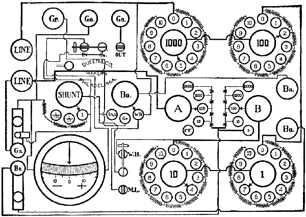
Fig. 579.--Diagram of the Queen dial decade portable testing set. Its dimensions are 9-1/2" long, 7" wide and 7" deep, and weighs 11-1/2 pounds. The resistances are arranged upon the dial decade plan, being placed in circuit by means of a rotating switch contact. The switches are so constructed that they may be turned in either direction, thereby permitting them to be turned quickly from the highest resistance in any dial to the lowest resistance in the same dial. This arrangement avoids the necessity of turning back through all the remaining resistances in any particular group of coils and is of value in locating swinging crosses or conditions of momentary balances. The connections for the various tests are made by the manipulation of one small knife switch (W.B.--M.L.) and the switch BA.; these are plainly lettered, thus avoiding the necessity of referring to a diagram of connections. In construction, the dial switches are made up of eight laminations of No. 28 B. & S. phosphor bronze, and the form is such as to prevent wearing grooves on the top of the contact studs. In this instrument the electrical circuits are soldered throughout excepting the switch contact whose resistance is negligible. The resistances are wound with manganin. The battery comprises six cells sub-divided which are easily replaceable. The galvanometer is the same as in the Queen acme set, but has the addition of an Ayrton shunt, which is useful in making insulation measurements. The necessary keys, binding posts, and switches are provided so as to facilitate the use of the instrument for the various measurements that can be made with it.
Table Showing the Best Values of Bridge Arms for Measuring any Desired Resistance
Value of Resistance being measured Best values of Position of Commutator Plugs as shown in fig. 582
A = B =
Below 1.5 ohms 1 1,000 PQ
Between 1.5 and 11 ohms 1 100 PQ
" 11 and 78 ohms 10 100 PQ
" 78 and 1,100 ohms 100 1,000 PQ
" 1,100 and 6,100 ohms 100 100 PQ or ST
" 6,100 and 110,000 ohms 1,000 100 ST
" 110,000 and 1,110,000 ohms 1,000 10 ST
" 1,110,000 and 11,110,000 ohms 1,000 1 ST
Ques. In testing with the Queen Acme set how should the plugs be placed in the commutator?
Ans. Always make the arm A the smaller except when the two arms are of equal value.
Ques. If the resistance being measured is higher than 6,100 ohms, or lower than 1,100 ohms, how should the commutator plugs be placed?
Ans. If higher than 6,100 ohms, they should be placed in the position ST; if lower than 1,100 ohms, in position PQ.
When the plugs are placed in the ST position, the unknown resistance is found by dividing the value of the larger bridge arm by that of the smaller, and multiplying the total employed resistance in the rheostat by the quotient. When the plugs are placed in the PQ position, the employed resistance in the rheostat is divided by the quotient.
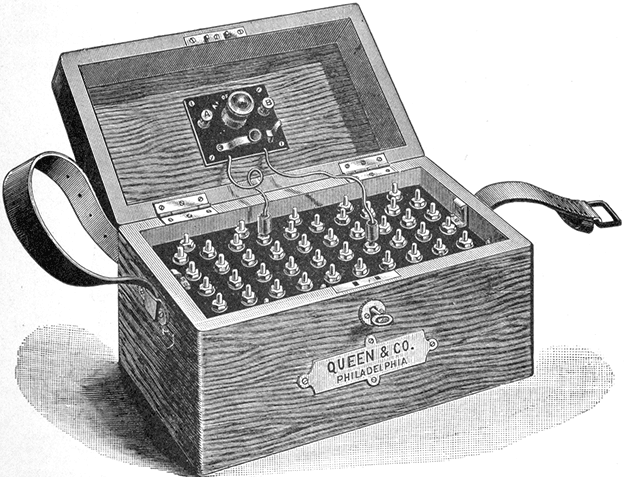
Fig. 580.--Queen portable silver chloride testing battery. The silver chloride cell has the advantage of long life, light weight, and compactness. The pressure of each cell when new is .8 volt.
Direct Deflection Method with Queen Acme Set.--To measure for instance, insulation resistance by direct deflection connect a known high resistance, say 100,000 ohms between the line post C (fig. 577), and the positive battery post. Remove all plugs from the commutator, and place all plugs in the rheostat, as any employed resistance in the rheostat will be in circuit with the galvanometer and the battery. Place the battery connection so as to throw only one cell into circuit. Now press the keys and obtain a deflection of the galvanometer needle. For example: assume that the needle to be deflected about 8 divisions of the scale. Since this deflection is due to the current from one cell passing through a resistance of 100,000 ohms, then 100,000 × 8 = .8 megohms represents the resistance through which one cell will produce a deflection of one division on the scale. Hence, .8 megohms is the constant of the galvanometer.
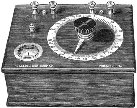
Fig. 581.--Ohmmeter. It consists essentially of a slide wire Wheatstone bridge, with the scale divided to read either directly in ohms, or in per cent. of a fixed resistance value. A galvanometer is mounted on the containing case of each, and battery and galvanometer keys are provided. In the direct reading type, the scale is so cut that when the galvanometer is balanced, the pointer of the instrument indicates the value of the resistance between the X posts. The scale is calibrated for any desired range. These ohmmeters being slide wire bridges, the greatest accuracy is at the center of the scale, hence one should be selected that will bring the part of the scale likely to be the most used at or near the center. A convenient type is that in which the scale is cut in per cent., 100 per cent. being at the center of the scale. Fixed coils of 1, 10, 100, 1,000 and 10,000 ohms are contained in the instrument with a plugging arrangement allowing any one to be used. When a balance is obtained, the actual resistance is determined by multiplying the dial reading by the value of the fixed coil in use. This amounts simply to shifting the decimal point. For instance, if the 100 ohm coil were being used, and the pointer were at .875, the resistance would be 87.5 ohms.
Now, replace the known high resistance (100,000 ohms) by the unknown resistance (for instance such as a cable) the value of which is to be determined. Add enough cells to produce as large a deflection of the needle as possible. Assume that 75 cells give a deflection of 1.5 scale division. Then, the galvanometer constant multiplied by the number of cells and the product divided by the deflection will give the insulation resistance of the cable; or
0.8 megohm × 75 cells = 60.0; and 60.0 ÷ 1.5 = 40 megohms
as the resistance of the cable.
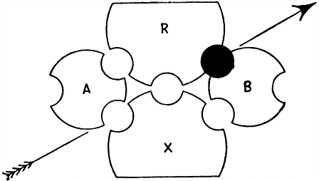
Fig. 582.--Commutator plug setting for comparing electromotive forces by the fall of potential method with Queen acme set.
Fall of Potential Method with Queen Acme Set.--To compare electromotive forces by this method, place the battery connection (fig. 577), so as to throw into circuit all the cells, taking care not to reverse them by crossing the battery cords. Plug the commutator as shown in fig. 582, and remove 1,000 ohms from bridge arm B. Place all plugs in arm A. From the rheostat unplug 5,000 ohms. Then connect one of the cells being tested, with its positive terminal to the + battery post and its negative terminal to the line post C.
When the keys are pressed, the galvanometer needle will swing either to the right or to the left. If it swing toward +, reduce the resistance in the rheostat; if it swing toward -, add resistance to the rheostat. When a value is found wherein a variation of an ohm either way reverses the deflection, add to this value the resistance unplugged in arm B, and divide the sum by the resistance in arm B. The result gives the ratio between the voltages of the testing set battery and cell being tested respectively. The division is decimal and may be readily accomplished by merely pointing off as many places as there are ciphers in the resistance employed from arm B. This operation repeated with any number of different cells, will give their voltages in terms of the voltage of the testing set battery, and from these ratios their relative values may be readily obtained.
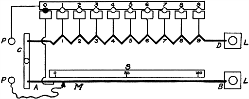
Fig. 583.--Diagram of apparatus for measuring low resistances based on the principle of the Kelvin double bridge. In the diagram AB represents a heavy piece of resistance metal of uniform cross section and uniform resistance per unit of length; CD is another piece of resistance metal of smaller cross section, and the two are joined together by a heavy copper bar, AC, into which both are silver soldered; LL are the current terminals and PP are the pressure terminals. The resistance of AB between the marks 0 and 100 on the scale S is .001 ohm. From the point 1 on the resistance CD to 0 on AB is also .001 ohm, from 2 to 0 is .002 and so on, and from 9 to 100 is .01 ohm. The slider M moves along the resistance AB and its position is read on the scale S which is divided into 100 equal parts and can be read by a vernier to thousandths. Subdivided in this way the resistance between the tap off points PP may have any value from .001 to .01 ohms by steps of .000001 ohm.
If the testing set battery be replaced by a standard cell, the first measurement gives at once the voltage of the cell tested.
If the voltage of the cell or battery being tested exceed that of the testing set battery, reverse the position of the two batteries, and the subsequent operations, as outlined above, will give the desired results.
How to check a Voltmeter with the Queen Acme Set.--In using a set as in fig. 576, first remove about 10,000 ohms from the rheostat, plug the commutator as shown in fig. 582, remove 100 ohms from the arm B, of the bridge, and connect a standard cell with the positive terminal to the + battery post and the negative terminal to the line post C. Then, connect the circuit to the battery posts of the testing set the positive lead to the + post and the negative lead to the - post. Now, press both keys and note the direction of the deflection of the galvanometer needle. If it move toward +, the rheostat resistance is too high; if toward -, too low.
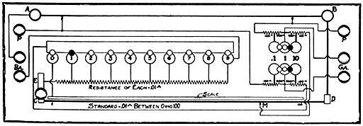
Fig. 584.--Kelvin bridge. This includes a low resistance standard of .1 ohm variable by steps of .00001 ohm, a set of ratio coils, and a holder for rods or wires to be measured, with a scale to measure their length. It is also provided with heavy flexibles to be used in measuring the resistances of irregularly shaped pieces. The connections are clearly shown in the diagram. The range of measurements of this bridge is: 1 ohm to .1 ohm by steps of .001 ohm readily estimated to .0001; .1 to .01 ohm by steps of .0001 ohm readily estimated to .00001; .01 ohm to .001 ohm by steps of .00001 ohm, readily estimated to .000001; .001 ohm down by steps of .00001 ohm, readily estimated to .000001 ohm.
Change the rheostat resistance accordingly until the balance attained is such that a very slight variation of the rheostat resistance one way or the other will reverse the galvanometer deflection. To find the pressure on the circuit, add 100 to rheostat resistance and point off two places. Multiply this value by the voltage and the product will be the desired voltage.
If the voltage of the standard cell be exactly one volt, the total employed resistance represents the voltage on the circuit.
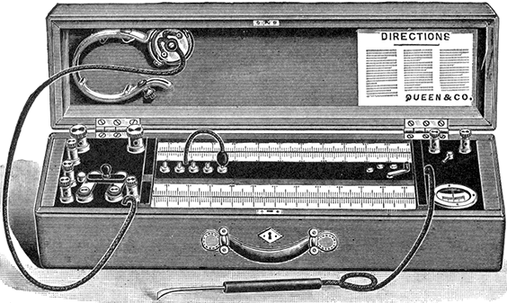
Fig. 585.--Queen slide wire bridge. It consists of a portable slide wire, Wheatstone bridge arranged to read directly in ohms in addition to its use for locating crosses and grounds. It is complete with battery, galvanometer and telephone receiver. The bridge is balanced by moving the hand stylus until the galvanometer shows no deflection or until there is no sound in the telephone receiver. In order to provide a wide range of measurement and maximum accuracy, ratio coils or multipliers having values of 1, 10, 100, 1,000 and 10,000 are provided. The scale of the instrument is arranged in two parts, one of which indicates ohms and the other is divided into uniform divisions for use when locating crosses and grounds by the Murray and Varley loop methods. A small induction coil is included so as to furnish an alternating current when using the telephone receiver.
For instance, in making a measurement on a 110 volt circuit, assume that the employing of 7,840 ohms rheostat resistance produces balance, and that increasing or decreasing this resistance by two ohms, reverses the galvanometer deflection. This indication that the setting 7,840 is uncertain, about 1/40 of 1 per cent. Since the rheostat coils are adjusted to an accuracy of only 1/5 of 1 per cent., that will be about the accuracy of the measurement.
If the pressure of the standard cell be 1.018 volts, then 7,840 + 100 = 7,940. Pointing off two places, gives 79.40, which multiplied by 1.018 gives 80.82 for the voltage on the circuit.
To Measure Internal Resistance of Cell with Queen Acme Set.--First compare its voltage on open circuit with the pressure of the testing set battery. Then, shunt the cell with a known resistance, about 100 ohms, and again measure its terminal voltage. The difference between the two values thus obtained, divided by the value of the shunt resistance, will give the value of the current. To find the internal resistance, multiply the value of the shunt resistance by the ratio between the first and second measured values.
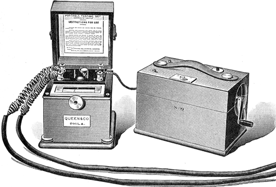
Fig. 586.--Evershed portable ohmmeter set. This testing set consists of a direct reading ohmmeter which indicates by direct reading the value of the resistance being tested, also a portable hand dynamo which provides at any required pressure the current necessary to make the test. It is adapted to the needs of supply stations, wiring contractors and dynamo builders. It is also useful in testing the insulation of underground and aerial cables, and is designed so that it can be used by ordinary workmen who are not experienced in handling delicate instruments and who, by its use, are able to obtain accurate results. The dynamo is wound for 100, 200, 500, or 1,000 volts, and is fitted with spring drum inside the case on which is coiled a twin flexible cord provided with a connector adapted for clamping under the ohmmeter terminals.
For instance, assume that the open circuit voltage of the cell being tested as compared with the voltage of the testing set battery is .212 of the latter, and that when it is shunted with a resistance of 1,000 ohms, its terminal voltage is .179. Then, the total resistance is to the 1,000 ohms shunt resistance as .212 is to .179 or (.212/.179) × 1,000 = 1,184, from which deducting the 1,000 ohms shunt resistance, gives 184 ohms as the internal resistance of the cell.
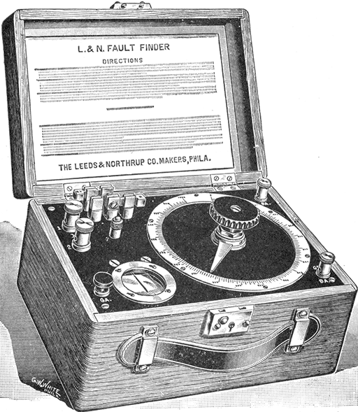
Fig. 587.--Leeds and Northrup fault finder. A lineman's instrument for the location of faults, crosses, grounds, and opens in telephone and telegraph circuits, and for the measurement of conductor and insulation resistance.
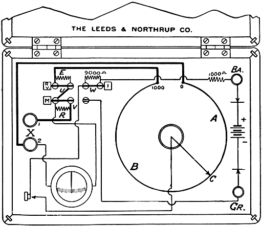
Fig. 588.--Diagram showing arrangement and connections of Leeds and Northrup fault finder. It is used to measure conductor resistance, fault resistance, to locate faults by four different tests, and when used with a buzzer and telephone, to locate opens. The essential feature of the instrument is the uniform resistance AB, which lies in a circle and which has a value of about 100 ohms. By a special construction, it is so arranged that the contact can be made at any point along it, and it is therefore equivalent to a very high resistance slide wire. It has a moving contact C and a uniform scale of 1,000 divisions. In series with this, there are the two resistances E and R which may be short circuited by the switches U and V. E has exactly the same resistance as the wire AB. R has a resistance of 100 ohms, and is the fixed resistance of the bridge arrangement for resistance measurements. The resistances of 1,000 ohms and 9,000 ohms connected to the battery post are to protect the battery and the apparatus from excessive current. The 9,000 ohms may be short circuited by the switch W.
Ammeter Test with Queen Acme Set.--Connect a low resistance in series with the ammeter and run leads from it to the testing set, the positive lead to the + battery post and the negative lead to the line post C (fig. 577). Insert a standard cell between the battery posts, with positive terminal to + battery post, and negative terminal to - battery post. Plug commutator as shown in fig. 582. Remove 10,000 ohms from rheostat, and 100 ohms from bridge arm B. Determine a balance in the usual way by changing the value of the resistance in the rheostat. This operation will balance the difference of pressure at the terminals of the shunt resistance against the standard cell, and its value is equal to
(1.40 × 100) / (R + 100) = 140 / (R + 100)
To determine the current flowing, divide the value of the difference of pressure thus obtained by the value of the shunt resistance.
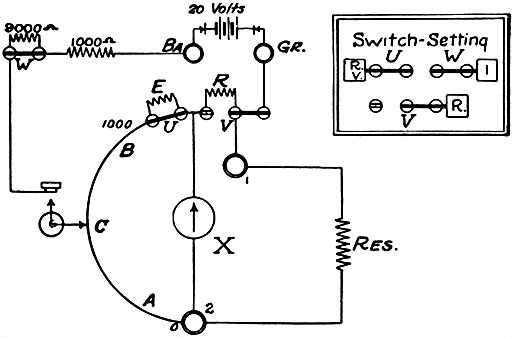
Fig. 589.--Resistance measurement with Leeds and Northrup fault finder. The diagram shows the proper connections and switch settings for measuring conductor resistance. As in the ordinary slide wire bridge, the resistance X between the two posts 1 and 2 is obtained from the formula X = A ÷ (1,000 - A) × R. To avoid the necessity of solving in each case the fraction A ÷ (1,000 - A), a table is furnished with the instrument, giving the value of this fraction for each value of A. The resistance is accordingly determined in each case by simply setting the contact C for a balance and reading from the table the resistance opposite the number corresponding to the scale reading and multiplying by 100, the value of R. To use an outside battery, remove the inside battery and connect the outside battery between the posts Gr and Ba. The pressure of this battery should not exceed 110 volts. If it exceed 25 volts, open switch W.
EXAMPLE--With an unknown resistance connected between the posts 1 and 2, the galvanometer showed a balance for a dial reading of 387. The number opposite 387 in the table is .6313; hence, X = .6313 × 100 = 63.13 ohms.
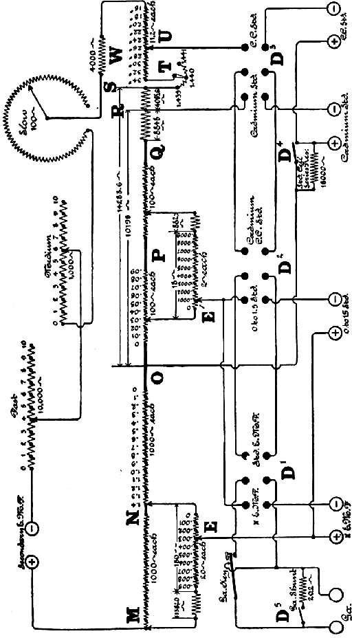
Fig. 590.--Diagram of the Queen standard potentiometer. The circuit arrangement is a method of sub-dividing the main potentiometer wire, MNOPQ, so as to provide for very accurate reading. The secondary voltage, or that used to supply current to the main potentiometer circuit, is adjusted by regulating rheostats, "Fast," "Medium," and "Slow" so that the current flow is exactly .0001 ampere. It is noted that this instrument requires a very small current for its operation. The instrument is direct reading for voltage measurements, not exceeding 1.4+. In order to determine if the current flow through the potentiometer be exactly .0001 ampere, the terminals of the standard cell binding posts are connected in circuit so that the drop over points between which they are connected are exactly equal to the voltage of the standard cell used. Binding posts are provided for connection with various standard cells. The unknown voltage to be measured is placed in opposition to the current flow in the potentiometer circuit by connecting to the binding post "XEMF." Observe that polarity is connected as required. The galvanometer with its shunt is placed in the standard cell circuit, or X circuit, by means of a double pole, double throw switch. The switch at T provides for standard cells of different values and the setting at U allows for temperature correction. The range of the instrument in volts can be increased by means of multipliers or volt boxes.
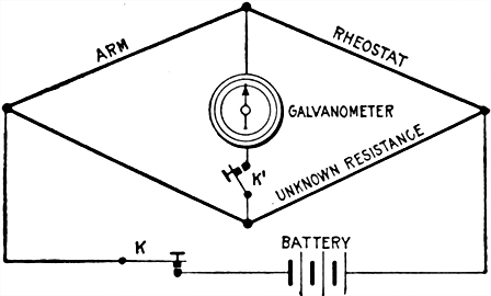
Fig. 591.
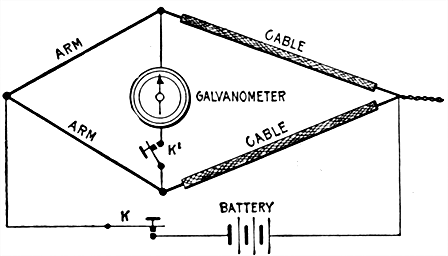
Fig. 592.
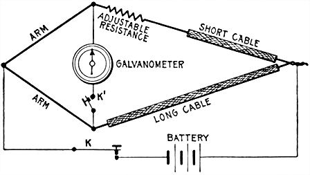
Fig. 593.
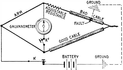
Figs. 591 to 594.--Diagrams illustrating loop testing. To properly understand the Murray or Varley loop tests, consider a Wheatstone bridge (fig. 591) the arms of which are equal. In loop testing, the rheostat is replaced by a length of cable and the unknown resistance also by a length of cable, as in fig. 592, both being similar in resistance per foot. If both lengths be the same, their resistances are the same and the bridge balances. Now shorten one cable and add resistance in series with it until the bridge again balances as in fig. 593. The added resistance equals that of the piece cut off. Hence, if the resistance per foot be known, the length of the shorter piece can be easily calculated. In the Murray and Varley tests, the battery circuit is by ground connections instead of by wire. In the Murray loop the arrangement is similar to fig. 592, the battery circuit being completed by ground connection through fault in defective cable. Fig. 594 shows the general arrangement of the Varley loop.
Loop Test.--This is a method of locating a fault in a telegraph or telephone circuit when there is a good wire running parallel with the defective one. In the process, the good and bad wires are joined at their distant ends and one terminal of the battery is connected to a Wheatstone bridge, while the other terminal is grounded. There are different ways of making loop tests as by:
The Murray loop;
The Varley loop;
Special loop.
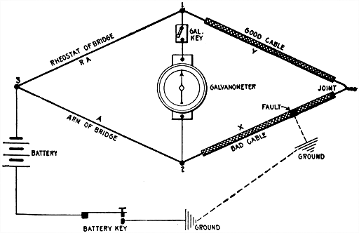
Fig. 595.--The Murray loop test. The apparatus is connected as in the figure. The rheostat of the bridge is used in place of the second arm to permit large adjustment. X and Y are the resistances of the cable between the fault and the points 1 and 2 respectively.
The Murray Loop.--In this test only one of the two regular bridge arms is used, the other being replaced by the rheostat giving an arm of large adjustment.
The connections are shown in fig. 595. In making the test, close key and note the deflection of the needle due to pressure of chemical action at fault, if any. This is called the false zero.
Now apply the positive or negative pole of the battery by depressing the battery key, and balance to the false zero previously obtained by varying the resistance in arms A or B. Then by Wheatstone bridge formula: RX=AY, and L=X+Y; Y=L-X, whence
X = A/(R+A) Y = L( R/(B+A) )
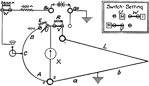
Fig. 596.--Murray loop method of fault location with Leeds and Northrup fault finder. Case I where there are two wires having equal resistance, in one of which there is a fault. Connect and set switches as shown; join the good wire to post 1 and the faulty wire to post 2. The resistance of E is equal to that of AB. From the symmetry of the arrangement, it is evident that, if the fault were exactly at the junction between the good and bad wires, the contact point C would rest for a balance at 1,000 on the scale, or at 500 if the fault were half-way along the bad wire; hence, at whatever point it comes to rest, the reading divided by 1,000 and multiplied by the length of the bad wire is the distance from the instrument to the fault.
EXAMPLE--In a pair of equal wires, 5.8 miles long, one is grounded. With the connections made as above, and the galvanometer balanced for the dial reading 124, the distance to the fault is (124 × 58) ÷ 1,000 = .7192 miles.
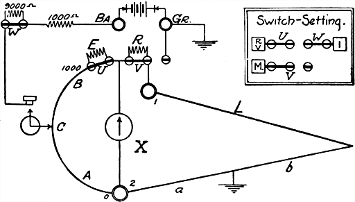
Fig. 597.--Murray loop method of fault location with Leeds and Northrup fault finder: Case II, where the good and bad wires are unequal. The figure shows the connections. It is the ordinary Murray loop and it is evident that the resistance a, to the fault will be obtained from the formula a = (A ÷ 1,000) × r, where r is the resistance of the loop, and A is the reading of the contact C on its scale. The distance d, to the fault is obtained from the formula d = Ar ÷ (1,000 × M), where M is the resistance per mile of the faulty wire.
EXAMPLE--A wire having a resistance M of 16.46 ohms per mile is grounded. This wire was looped with a wire of unknown resistance and the total resistance of the loop r was measured and found to be 54.07 ohms. Connections were made as in the figure, and the reading A was found to be 332. Substituting these values in the above formula: d = (332 × 54.07) ÷ (1,000 × 16.46) = 1.09 miles.
Ques. How may the distance from 2 to the fault be determined in knots or miles.
Ans. Divide Y by resistance per knot or mile.
The Varley Loop.--This is a method of locating a cross or ground in a telephone or telegraph line or other cable by using a Wheatstone bridge in a loop formed of a good wire and the faulty wire joined at their distance ends. One terminal of the battery is grounded and the other connected to a point on the bridge at the junction of the ratio arms. The rheostat arm then includes the resistance of the rheostat plus the resistance of the fault, while the unknown arm includes the resistance of the good wire plus the resistance of the bad wire beyond the fault. When the bridge is balanced, the unknown resistances may be readily determined by a simple equation.
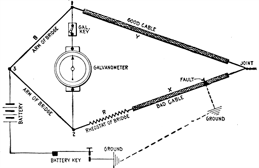
Fig. 598.--The Varley loop test. The diagram shows the various connections. X and Y are the resistances of the cable between the fault and the points 1 and 2 respectively. L is the resistance of the good and bad cable or X + Y.
In making the Varley loop test, the resistance of looped cable or conductors is measured, and then connected as in fig. 598. Close the battery key and adjust R for balance.
When earth current is present, the best results are obtained when the fault is cleared by the negative pole, and just before it begins to polarize. If X be the resistance from 2 to the fault, then
X = (L - R) / 2
also, X divided by the resistance of the cable or conductor per knot or mile gives the distance of fault in knot or miles.
When the resistance of the good wire used to form a loop with the defective wire, together with that portion of the defective wire from the joint to the fault is less than the resistance of the defective wire from the testing station to the fault, the resistance R must be inserted between point 1 and the good conductor, the defective wire being connected directly to point. The formula in this case is
X = (L + R) / 2
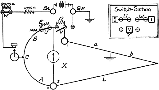
Figs. 599 and 600.--Varley loop method of fault location with Leeds and Northrup fault finder. This method may be used as a check on the Murray methods. Connect the faulty wire to 1, and measure the resistance of the loop. Then throw switches as shown in the fig. 600. Let: a = resistance to fault, d = distance to the fault in miles, M = resistance of the faulty wire per mile, r = resistance of the loop, R = resistance of the coil R, or 100 ohms, T = A ÷ (1,000 - A) to be read from the table. From the Wheatstone bridge relation: a = (r - 100T) ÷ (T + 1), and d = (r - 100T) ÷ (T + 1)M.
EXAMPLE--A wire having a resistance of 16.46 ohms per mile is grounded. This was looped with a wire of unknown resistance and the resistance of the loop was found to be 54.07 ohms. Connections were made as in the figure, and the reading A was found to be 234. From the table T = .3055, and substituting: d = (54.07 - 30.55) ÷ (1.3055 × 16.46) = 1.094 + miles.
Special Loop.--This method may be used to advantage where the length of the cable or faulty wire only is known and where there are two other wires which may be used to complete the loop. It is not necessary that the resistance of the faulty wire and the length and resistance of the other wires be known. Figs. 601 to 604 show the connections and method of testing.
EXAMPLE.--All the wires in a cable 10,852 ft. long were found to be grounded so that none of them could be used as good wires. Two wires were selected out of another cable going to the same place by a different route and securely joined to one of the grounded wires at the distant end. This grounded wire and one of the good ones were connected as shown in figs. 601 and 602 and the reading A was found to be 307. Connections were then made as shown in figs. 603 and 604 and A was found to be 610. What is the value of d?
According to formula
d = AL/A = (307 × 10,853)/610 = 5,461 ft.
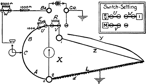
Figs. 601 and 602.--Special loop test with Leeds and Northrup fault finder. For the first measurement connect the faulty wire to 2, either of the good wires, as Z, to 1, the post Gr to ground, and short circuit the coils R and E by closing switches U and V as in the figures. Balance in the usual way and call the dial reading A. For the second measurement, connect the post Gr. (disconnected from ground), to the other good wire y as shown in figs. 603 and 604, and get another balance; call this reading A'. The distance d, to the fault is determined from the simple formula d = AL ÷ A' where L is the length of the cable or faulty wire.
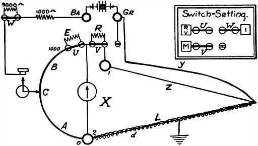
Figs. 603 and 604.--Special loop test as made with the Leeds and Northrup fault finder. Diagram showing connections for the second measurement. The special loop test may be used to advantage where the length of the cable or faulty wire only is known, and where there are two other wires which may be used to complete the loop. To use an outside battery, connect one pole to Ba, and ground the other. The pressure of this battery must never exceed 110 volts; if it be over 25 volts, see that switch W is open.
The Potentiometer.--For the rapid and accurate measurement of voltage, current, and resistance, the potentiometer can be recommended. Those in charge of electric light and power companies, and also those who purchase large amounts of electrical energy are realizing, more and more, the necessity of having satisfactory primary standards with which to check their volt-, ampere-, and watt-meters.
When it is realized that an error of one per cent. in a commercial instrument means an error of one dollar one way or the other in every one hundred dollars charged, the need of such standardization apparatus becomes at once apparent.
The potentiometer, it should be noted, relies for its accuracy, only upon the constancy and accuracy of resistances and upon standard cells.
With the materials now available, and the skill which has been acquired in their manufacture, both the resistances and the standard cells are obtainable which are remarkably constant, and both can be readily checked for accuracy.
Location of Opens.--These measurements are based on the fact that the capacity of wires in a cable is ordinarily a measurable quantity, which, in wire of uniform diameter, is proportionate to length. In making these tests, a fault finder is used together with a buzzer, dry cells to operate it, small induction coil, and telephone receiver. These instruments are to be found in any telephone exchange. It is best to locate the buzzer at some distance from the fault finder in order that it cannot be heard by the operator.
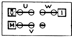
Fig. 605.--To use galvanometer of Leeds and Northrup fault finder in series with the battery: Set switches as shown, and connect between posts Gr. and 2 (see figs. 587 and 588). The galvanometer will have the maximum sensibility with the pointer at 1,000 and the minimum at zero.
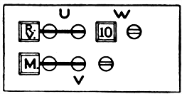
Fig. 606.--To measure high resistances, such as the resistances of faults with Leeds and Northrup fault finder. First Method.--Arrange the switches as shown in the figure. Connect posts Gr. and 2, turn the handle until the galvanometer needle comes to rest at an even deflection of ten divisions. Call the reading A. Connect in the unknown resistance between Gr. and 2. Now close the switch W, so that the figure 1 appears on the top of the block, and again bring the galvanometer to a deflection of ten divisions and call the reading B. Then X = (10,000 B ÷ A) - 1,000. In case X be a high resistance, it will be found that the galvanometer will not deflect ten divisions for any position of the pointer. In such case, choose a number of divisions which is a factor of ten, such as 5, 2, or 1, and multiply (10,000 B ÷ A) by ten divided by the number chosen, as 10/5, 10/2, 10/1. For example, for a deflection of two divisions: X = (10/2)(10,000 B ÷ A) - 1,000. The satisfactory range of the set for high resistance measurement may be increased by using an outside battery of higher voltage. With the contained battery, satisfactory measurements can be made up to 1 or 2 megohms. When outside battery is used, connect one terminal to the post Ba, and the other to 2 for the reading A. Connect the battery and unknown resistance in series between these posts for the reading B. When an outside pressure of 25 volts or over is used, the switch W should not be closed unless there be a resistance in series with the battery of 10,000 ohms or over. Second Method.--For use as a voltmeter to measure high resistances. (More convenient but not quite as accurate as first method.) Set the switches to RV, M and 10. Turn the knurled nut on the galvanometer so as to set the needle to the extreme right hand side of the scale. Connect the posts 2 and Gr. with a short piece of wire. Turn the rotating pointer on the scale until the galvanometer needle moves over about 20 scale divisions when the battery key is closed. Remove the connection between 2 and Gr. as the voltmeter terminals. This makes a simple way of testing for various kinds and amounts of trouble. On a wet cable a deflection of 10 to 15 divisions indicates heavy enough trouble to locate with the fault finder. With a little care, trouble showing only 5 or 6 divisions can be located.
Before attempting locations for opens it is well to make the following measurements:
1. The insulation of the broken wire and the insulation of the good wire with which it is to be compared.
This may be done as shown in fig. 606. It is best that the insulation resistance be fairly good, but experiments indicate that good results can be obtained by the methods which follow, even when the insulation is as low as 100,000 ohms, and fair results when as low as 50,000 to 100,000 ohms.
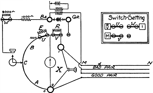
Fig. 607.--Diagram of connections in testing for opens with Leeds and Northrup fault finder. The apparatus required consists of fault finder, buzzer, dry cell to operate buzzer, small induction coil, and telephone receiver. Connect the battery to the primary of the induction coil, one terminal of the secondary to the post Ba, and the other to the connected wires as shown. Set switches U and V so as to short circuit the two resistance coils.
2. The resistance between the two sections of the broken wire should be measured.
This may be done by joining the broken wire and a good wire at the distant end of the cable and measuring the resistance of the loop. To ensure close locations, this resistance should be over 100,000 ohms. Fair locations can be made when the resistance is much lower and it is worth while to attempt it even if the resistance be as low as 10,000 ohms. The difficulty of determining the balance point increases as the resistance decreases.
Ques. Describe the method of locating an open with a fault finder.
Ans. (Case I) The broken wire will be one of a pair. Select another pair in the cable that will have the same capacity per mile and join together the mate of the broken wire and one wire of the other pair. Make the connections as shown in fig. 607, then depress the battery key and move the contact to the point of minimum sound in the telephone. The distance to the break is equal to LA ÷ (1,000 - A), where L is the length of the good wire.
EXAMPLE: A cable 1.45 miles long contained a broken wire. It was found that the insulation resistance of the end of this wire was over 10 megohms, as was that of the good pair selected to test against it. The resistance between the two pieces of the good wire was also over 10 megohms. Connections were made as in fig. 607, and it was found that the balance point was 476. Accordingly from the table
A / (1,000 - A) = 0.9084
and
d = 1.45 × .9084 = 1.317 + miles.
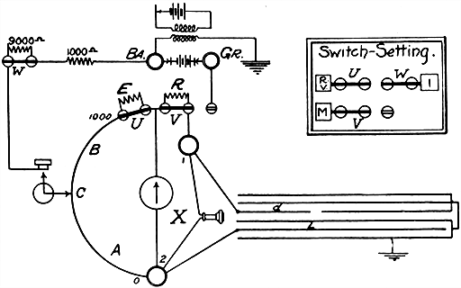
Fig. 608.--Diagram of connections in testing with Leeds and Northrup fault finder for open wire in telegraph and other cables in which the wires are not grouped in pairs. Connect the broken wire to 1. Select a good wire and join to 2. Connect all other wires and ground them, by connecting to the cable sheath. Connect the distant end of the broken wire to the others. Ground the end of the induction coil that is not connected to the post Ba.
Location of Opens.--(Case II) Open wire in telegraph or other cables in which the wires are not grouped in pairs. The connections are made as in fig. 608, and the measurement and calculation exactly as in the preceding case.
The accuracy of the location of both of the above methods depends on the good and broken pair, or the good and broken wires having equal and uniform capacity per unit length. It is not always possible to select wires that are alike in this respect. In such cases, as for instance, where there is no good wire in the cable containing the broken wire, and a good wire has to be selected from another cable, the method of Case III may be used.