IRON. (continued 2)
Reading edition
“The loss in weight of crude iron during its conversion into an ingot of malleable iron was found, on a mean of four experiments, to be 12½ per cent., to which will have to be added the loss of metal in the finishing rolls. This will make the entire loss probably not less than 18 per cent. instead of about 28 per cent., which is the loss on the present system. A large portion of this metal is however recoverable by heating with carbonaceous gases the rich oxides thrown out of the furnace during the boil. These slags are found to contain innumerable small grains of metallic iron, which are mechanically held in suspension in the slags and may be easily recovered.
“I have before mentioned that after the boil has taken place a steady and powerful flame succeeds, which continues without any change for about ten or twelve minutes, when it rapidly falls off. As soon as this diminution of flame is apparent the workman will know that the process is completed, and that the crude iron has been converted into pure malleable iron, which he will form into ingots of any suitable size and shape by simply opening the tap-hole of the converting vessel and allowing the fluid malleable iron to flow into the iron ingot moulds placed there to receive it. The masses of iron thus formed will be free from any admixture of cinder, oxide, or other extraneous matters, and will be far more pure and in a forwarder state of manufacture than a pile formed of ordinary puddle bars. And thus it will be seen that by a single process, requiring no manipulation or particular skill, and with only one workman, from three to five tons of crude iron pass into the condition of several piles of malleable iron in from thirty to thirty-five minutes, with the expenditure of about a third part the blast now used in a finery furnace, with an equal charge of iron, and with the consumption of no other fuel than is contained in the crude iron.
“To those who are best acquainted with the nature of fluid iron, it may be a matter of surprise that a blast of cold air forced into melted crude iron is capable of raising its temperature to such a degree as to retain it in a perfect state of fluidity after it has lost all its carbon and is in the condition of malleable iron, which, in the highest heat of our forges, only becomes softened into a pasty mass. But such is the excessive temperature that I am enabled to arrive at with a properly shaped converting vessel and a judicious distribution of the blast, that I am enabled not only to retain the fluidity of the metal, but to create so much surplus heat as to remelt all the crop-ends, ingot-runners, and other scrap that is made throughout the process, and thus bring them, without labour or fuel, into ingots of a quality equal to the rest of the charge of new metal....
“To persons conversant with the manufacture of iron, it will be at once apparent that the ingots of the malleable metal which I have described will have no hard or steely parts, such as are found in puddled iron, requiring a great amount of rolling to blend them with the general mass, nor will such ingots require an excess of rolling to expel cinder from the interior of the mass, since none can exist in the ingot, which is pure and perfectly homogeneous throughout, and hence requires only as much rolling as is necessary for the development of fibre; it therefore follows that, instead of forming a merchant bar, or rail, by the union of a number of separate pieces welded together, it will be far more simple and less 61expensive to make several bars or rails from a single ingot. Doubtless this would have been done long ago had not the whole process been limited by the size of the ball which the puddler could make.
“The facility which the new process affords of making large masses will enable the manufacturer to produce bars that, in the old mode of working, it was impossible to obtain; while at the same time it admits of the use of more powerful machinery, whereby a great deal of labour will be saved and the process be greatly expedited.... I wish to call the attention of the meeting to some of the peculiarities which distinguish cast steel from all other forms of iron, viz., the perfectly homogeneous character of the metal, the entire absence of sand-cracks or flaws, and its greater cohesive force and elasticity, as compared with the blister steel from which it is made,—qualities which it derives solely from its fusion and formation into ingots, all of which properties malleable iron acquires in like manner by its fusion and formation into ingots in the new process; nor must it be forgotten that no amount of rolling will give the blister steel, although formed of rolled bars, the same homogeneous character that cast steel acquires by a mere extension of the ingot to some ten or twelve times its original length....
“I beg to call your attention to an important fact connected with the new process which affords peculiar facilities for the manufacture of cast steel. At that stage of the process immediately following the boil the whole of the crude iron has passed into the condition of cast steel of ordinary quality. By the continuation of the process the steel so produced gradually loses its small remaining portion of carbon, and passes successively from hard to soft steel, and from soft steel to steely iron, and eventually to very soft iron; hence, at a certain period of the process, any quality of metal may be obtained. There is one in particular which by way of distinction I call semi-steel, being in hardness about midway between ordinary cast steel and soft malleable iron. This metal possesses the advantage of much greater tensile strength than soft iron; it is also more elastic, and does not readily take a permanent set, while it is much harder and is not worn or indented so easily as soft iron; at the same time it is not so brittle or hard to work as ordinary cast steel. These qualities render it eminently well adapted to purposes where lightness and strength are specially required, or where there is much wear, as in the case of railway bars, which from their softness and lamellar texture soon become destroyed. The cost of semi-steel will be a fraction less than iron, because the loss of metal that takes place by oxidation in the converting vessel is about 2½ per cent. less than it is with iron; but as it is a little more difficult to roll, its cost per ton may fairly be considered to be the same as iron; but as its tensile strength is some 30 or 40 per cent. greater than bar iron, it follows that for most purposes a much less weight of metal may be used than that so taken. The semi-steel will form a much cheaper metal than any we are at present acquainted with. These facts have not been elicited from mere laboratory experiments, but have been the result of working on a scale nearly twice as great as is pursued in our largest iron works, the experimental apparatus doing 7 cwt. in thirty minutes, while the ordinary puddling furnace makes only 4½ cwt. in two hours, which is made into six separate balls, while the ingots or blooms are smooth, even prisms, 10 in. square by 30 in. in length, weighing about equal to ten ordinary puddle balls.”
The startling novelty of the methods and results described in this 62paper had the effect of paralyzing discussion at the time. But soon the voice of detraction was heard; many iron-masters ridiculed the idea of producing iron and steel without fuel, and indeed it may have been observed, the title of the paper notwithstanding, that first the silicon and carbon, and then the iron itself, really supplied the fuel. And we must remember that malleable iron in a molten state was then deemed an impossibility, for the hottest furnaces then known could not effect the fusion, however prolonged their action might be, yet Bessemer was to obtain five tons in this condition in the short space of half an hour with no other aid than cold air. Then it was said that Bessemer’s process of forcing air into melted cast iron had no claim of novelty, for it had been tried before and found valueless. Some iron-masters on trying experiments on a small scale and with imperfect appliances met with failures, and discredited the process at once; but five large establishments paid for licences sums amounting to £26,500 within three weeks of the reading of the paper. At the works of the Dowlais Iron Co., in South Wales, who were the first licensees, the first converter was set up under Bessemer’s personal superintendence, and at the first operation five tons of iron were produced direct from the blast furnace pig. This apparently satisfactory result proved quite otherwise when this iron came to be practically tested; for it was found quite useless! It was both “cold-short” and “red-short,” to use the technical terms,—the former of which means that although the sample may be welded, it is when cold brittle and rotten; the latter means that at a low red heat it breaks and crumbles under the hammer. Further trials were made, new experiments instituted, but the success that attended Bessemer’s early experiments could not be repeated, and as yet no one knew the reason why. Now it so happened that in the preliminary experiments an exceptionally pure pig iron had been made use of containing little or no phosphorus or sulphur, substances very deleterious in iron, and still more so in steel. With the capital obtained by the sale of his licences Bessemer quietly set to work to investigate the cause of his non-success, making daily experiments with a ton or two of metal at a time. These experiments extended over a period of two and a half years, and upon them Bessemer and his partner spent about £16,000, besides the £4,000 the preliminary researches had cost. But all difficulties were at length overcome, and the process was now found capable of turning out pure iron and steel when the pure pig iron of Sweden was used in the converter. In the meantime the licensees had made no attempts practically to carry out the process, which began to be denounced as visionary: it was “a mare’s nest”; it was “a meteor that had passed through the metallurgical world, but had gone out with all its sparks.” When Bessemer again brought the subject before the public, he found that no one believed in it; everyone said, “Oh, this is the thing that made such a blaze two or three years ago, and which was a failure.” Neither iron-makers nor steel-makers would now take it up. Bessemer and his partner thereupon joined with three other gentlemen to establish at Sheffield a steel-works of their own, where the invention should be carried into full practice. In due time works were erected, and they commenced to sell steel, receiving at first very paltry orders, for such quantities as 28 lbs. or 56 lbs.; but the orders soon became larger, and afterwards very much larger, for they were underselling the Sheffield manufacturers by £20 a ton, and their steel was undistinguishable from 63the higher priced article. Bessemer had now bought his licences back again, and in the course of his second set of experiments had patented each improvement as it occurred to him, finally bringing the mechanical apparatus to the degree of efficiency requisite for practical working, without which his primary idea would have been valueless. Before directing the reader’s attention to the form the apparatus had assumed, we may transcribe what Mr. Jeans, in the work above referred to, has told about the commercial success of the Bessemer steel-making firm:—
“On the expiration of the fourteen years’ term of partnership of this firm the works, which had been greatly increased from time to time out of revenues, were sold by private contract for exactly twenty-four times the amount of the whole subscribed capital, notwithstanding that the firm had divided in profits during the partnership a sum equal to fifty-seven times the gross capital, so that by the mere commercial working of the process, apart from the patent, each of the five partners retired after fourteen years from the Sheffield works with eighty-one times the amount of his subscribed capital, or an average of nearly cent. per cent., every two months,—a result probably unprecedented in the annals of commerce.”
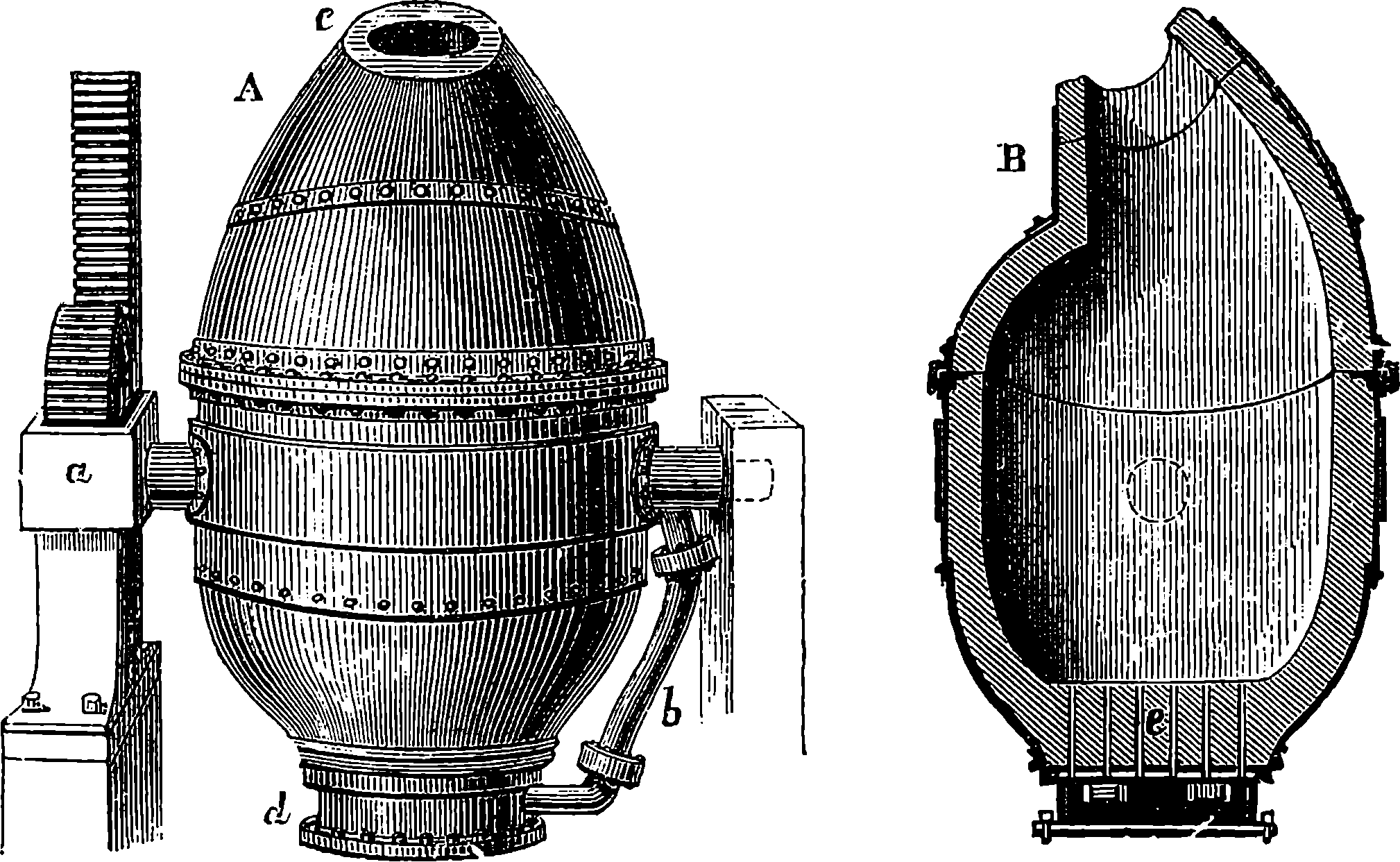
Fig. 24.—Bessemer Converter. A, Front view, showing the mouth, c; B, Section.
The form of the Bessemer apparatus as it finally left the inventor’s hands may now be considered: but in certain details and arrangements some modifications, dictated by the experience and requirements of individual establishments, have been made, leaving the principles of the apparatus unchanged. Thus instead of making the converting vessel turn on trunnions, it is sometimes constructed fixed, the fluid metal after conversion being let out at a tap-hole; the number and size of the tuyères are varied; and so with the disposition of the air chamber or tuyère box, the pressure of the blast, the capacity of the converter itself, etc. In capacity converters vary between 2½ tons and 10 tons; one of medium size is shown in elevation and section in Fig. 24, and may 64be described as an egg-shaped vessel about 15 ft. high and 6 ft. diameter inside. It is strongly made of wrought iron in two parts bolted together, and is lined inside with some thick infusible coating, of which more is to be said presently. The converter swings on trunnions, one of which is hollow, and admits the blast by the pipe b to the base of the vessel, whence it passes through the passages shown at e. The thickness of the lining at e may perhaps be 20 in., and passages for the air are perforated in fire-clay tuyères, of which there may be seven, each with seven perforations of half an inch diameter. To the other trunnion is attached a toothed wheel which engages the teeth of a rack receiving motion from hydraulic pressure. The iron for the operation is melted in a furnace having its hearth above the level of the converter; and to receive its charge the latter is turned so that the molten cast iron may be poured in from a trough until its surface is nearly on a level with the lowest of the tuyères. The blast having been turned on, the hydraulic power is set to work and the converter is slowly brought to an upright position. The pressure of the current of air prevents any of the fluid metal from entering the blow-holes. The blast of cold air is continued until all the silicon and carbon have been removed by oxidation. If the production is to be steel, there is then added to the contents of the converter, placed in position to receive it, a certain weight of melted cast iron of a special constitution, and the blow is resumed for a few minutes; or in more recent practice this special metal is added to the fluid metal run out of the converter into a spacious ladle in known quantity. On this addition an intense action takes place, attended by an extremely brilliant flame and a throwing out of cinder or slag. The metal thus added to the decarbonized iron is a carbonized alloy of iron and manganese obtained from an ore naturally containing the latter metal, and scarcely any phosphorus or sulphur. The charcoal pig from this ore is called spiegeleisen (German = mirror-iron) from its brilliant reflecting facets; it contains from 12 to 20 per cent. of manganese, with about 5 per cent. of carbon, and a considerable proportion of silicon. An exact chemical analysis of the particular spiegeleisen having been previously made, it is known what proportion of it is to be added to the decarbonized iron in order to convert this into a steel with any required content of carbon. The manganese probably acts by combining with oxide of iron diffused through the mass, and together with the silicon forming the very easily separated slag which is ejected.
The whole series of operations connected with the Bessemer process may be easily followed by the help of Fig. 25, which is taken from a beautiful model in the Museum of Practical Geology. This model, which was presented to the museum by Mr. Bessemer himself, represents every part of the machinery and appliances of the true relative sizes. C is the trough, lined with infusible clay, by which the liquid pig iron is conveyed to the converters, A. The hydraulic apparatus by which the vessels are turned over is here below the pavement, but the rack which turns the pinion on the axis of the converter is shown at B. The vessel into which the molten steel is poured from the converter is marked E, and this vessel is swung round on a crane, D, so as to bring it exactly over the moulds, placed in a circle ready to receive the liquid steel, which on cooling is turned out in the form of solid ingots. The valves which control the blast, and those which regulate the movements of the converter through the hydraulic apparatus, are worked by the handle seen at H. The 66crane, or revolving table, D, is also under perfect control, so that the crude pig iron is converted into steel, and the moulds are filled with a rapidity and ease that are positively marvellous to a spectator.
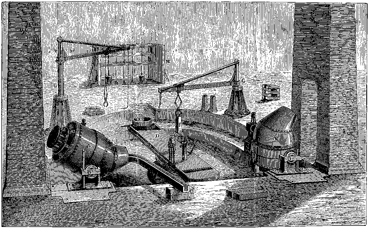
Fig. 25.—Model of Bessemer Steel Apparatus.
The development of the Bessemer process soon had the effect of so reducing the price of steel that this material came into use for almost every purpose for which iron had previously been employed, such as railway bars, girders, etc., for bridges, boiler plates, etc., for all which “steely iron” containing only 0·12 to 0·40 per cent. carbon proved admirably adapted. The practical success of the Bessemer process had not long been demonstrated commercially by the inventor and his partners at Sheffield before other firms began the manufacture: so that in 1878 there were in Great Britain alone twenty-seven establishments making Bessemer steel and using 111 converters. It may give an idea of the magnitude the Bessemer steel manufacture had attained even at that time if we quote the cost of erecting a complete plant for two 5–ton converters: it was £44,400, as given in a detailed estimate. In all these cases pig iron from ores free from phosphorus and sulphur had to be used, for as we have seen the converter failed to eliminate these vitiating elements. Imported pig ores had in general to be used, or pig from the limited supply of British hæmatite ores in West Cumberland. The Barrow Hæmatite Steel Company engaged in the production of Bessemer steel on a very large scale, having by 1878 erected no fewer than sixteen converters of the capacity of 6 tons each. In the meanwhile many efforts were made to discover some method of eliminating phosphorus, so that the ordinary qualities of British pig iron, and iron derived in any part of the world from the coarse phosphorized ores, might be available for the converter. Many of the methods then devised proved correct in principle and feasible in practice; but as, for sundry reasons, none of them came extensively into use, we need not here allude to them further.
The solution of the problem was announced in 1879. Some years before, G. J. Snelus had come to the conclusion that with a siliceous lining it would be impossible to eliminate phosphorus in the Bessemer converter, and that some refractory substance of a basic character must be sought for in order that the slag produced should be in a condition to absorb the phosphoric acid as fast as it is produced. He patented in 1872 the use of magnesian limestone as a material for the lining; as that substance when intensely heated became very hard and stony, being in that condition quite unaffected by water. Two young chemists, Messrs. Thomas and Gilchrist, apparently without being aware of Mr. Snelus’s conclusions, had also convinced themselves that the chief deficiency in the Bessemer process was due to the excess of silica in the slag, and in 1874 they began to try the effect of basic linings, and also of basic additions, such as lime, etc., to the charge in the converter, so that the lining itself should not be worn out by entering into the slag. Their results proved that phosphorus could be eliminated when the slag contained excess of a strong base. An example of an operation at Bolckow, Vaughan, & Company’s Eston works with the highly phosphorized Cleveland pig iron may be quoted. The basic-lined converter received first 9 cwt. of lime, then 6 tons of metal. When the blast at 25 lbs. pressure was turned on, the silicon began at once to burn; for three minutes the carbon was not affected, but for fourteen minutes longer it regularly diminished, the silicon keeping pace with it. After 67the blow had been continued for thirteen minutes from the commencement, the converter was turned down to allow of the further introduction of 19½ cwt. of a mixture of two parts of lime with one of oxide of iron. So long as 1·5 per cent. of carbon remained in the metal the phosphorus was untouched, and at the end of the blow, i.e. when the flame dropped, only one-third of it had been eliminated; it still formed 1 per cent. of the metal. The blast continued for another two minutes brought it down to ¼ per cent., and in one more minute only a trace was left. Most of the sulphur was got rid of at the same time. From Cleveland pig, thus de-phosphorized in the Bessemer converter, large quantities of steel rails were rolled for the North Eastern Railway Company, and were found entirely satisfactory, being as good as those made from the Cumberland hæmatite steel. This de-phosphorized process has been brought into operation wherever phosphoric ores are dealt with, and it has been applied with equal success in the “open hearth” furnaces, of which we have now to speak.
All discoveries and all inventions may be traced back to preceding discoveries and inventions in an endless series, and it is only by its precursors that each in its turn has been made possible. If we take one of the greatest marvels brought into existence at nearly the close of our epoch, namely, “wireless telegraphy,” we may follow up links of a chain connecting it with the recorded observations of an ancient Greek (Thales) who flourished seven centuries before our era, and even these may not have been original discoveries of his. And it will have been gathered from what has already been said that steel must have been produced, however unwittingly, at the earliest period at which man began to reduce iron from its ores. So the very latest, and for many purposes the most extensively practised, process of modern steel-making, brought indeed to working perfection mainly by the perseverance and scientific insight of two individuals, is the result of the observation and the accumulated experience of former generations. The observations and experience here alluded to are chiefly those that follow two lines: one concerning the properties of the metal itself, the other relating to the means of commanding very high temperatures on a great scale. On this occasion we are able almost to lay a finger on some proximate links of the chain. Réaumur, the French naturalist, made steel in the early part of the eighteenth century by melting cast iron in a crucible, and in this liquid metal he dissolved wrought iron, the product being, as the reader will now easily understand, the intermediate substance, steel; and this was obtained of course at a temperature which was incapable of fusing wrought iron by itself. He published in 1722 a treatise on “The Art of converting Iron into Steel, and of softening Cast Iron.” For this, and certain other metallurgical discoveries, Réaumur received a life-pension equivalent to about £500 per annum,—a treatment very different from that dealt out by the British to Henry Cort. The action in Réaumur’s crucible is precisely that used on the large scale in Siemens’ open hearth. But this last became possible only when Siemens had worked out his “regenerative stove” or heat accumulator, the development of an idea suggested by a Dundee clergyman in 1817.
A general notion of the Siemens’ regenerative stove will have been already gained from the account given before of its application to the modern type of blast furnace. Of the inventor himself, C. William Siemens, it may be observed that he was one of a family of brothers, all 68remarkable for their scientific attainments, and in many of his researches and processes he was aided by his brothers Frederick and Otto. In our article on “Electric Power and Lighting” there will be found some notice of a few of Siemens’ inventions pertaining to those subjects. A still more admirable invention of his is the electric pyrometer, an instrument of the utmost utility for measuring, with an accuracy previously unapproachable, the high temperature of furnaces, etc. Indeed there are few departments of science, pure or applied, which have not been enriched by the researches and contrivances of this distinguished man, whose merits were acknowledged by the bestowal upon him of the highest scientific and academical honours, and also of a title, for he became Sir William Siemens.
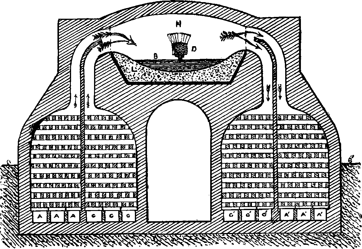
Fig. 26.—Section of Regenerative Stoves and Open Hearth.
Siemens was much engaged from 1846 in conjunction with his brother Frederick in experimental attempts, continued over a period of ten years, at the construction of the regenerative gas furnace. At length, in 1861, he proposed the application of his furnace to an “open hearth,” and during the next few years some partial attempts to carry out his process were made, and he himself had established experimental works at Birmingham in order to mature his processes, while Messrs. Martin of Sireuil, in France, having obtained licences under Siemens’ patents, gave their attention to a modification of his process, by which they succeeded in producing excellent steel. Siemens having in 1868 proved the practicability of his plans by converting at his Birmingham works some old phosphorized iron rails into serviceable steel, a company was formed, and in 1869 the Landore Siemens’ Steel Works were established at Landore in Glamorganshire, and a few years after, these had sixteen Siemens 69open hearth melting furnaces at work, giving a total output of 1,200 tons of steel per week. The number of furnaces was subsequently increased. Extensive works specially designed for carrying out the Siemens and the Siemens-Martin process were shortly afterwards erected at other places, as at Newtown, near Glasgow, Panteg in Wales, etc. In Great Britain the open hearth process gradually gained upon the Bessemer, until in 1893, when the total output of both kinds amounted to nearly 3,000,000 tons, this was almost equally divided between them, and since that period the steel made by the former has greatly surpassed in amount that made by the latter.
How the regenerative stove, or heat accumulator, works, and how it is applied in the open hearth process, the reader may learn by aid of the diagram Fig. 26, in which however no representation of the disposition of the parts in any actual furnace is given, nor any details of construction beyond what is necessary to make the principle clear. On the right and on the left of the diagram will be seen a pair of similar chambers which are shown as partly below the level of the ground S S´, such being a usual disposition. The outer walls of these chambers are thick and the interior is entirely lined with the most refractory fire-bricks, of which also is formed the partition in between each pair of compartments, as well as the passages from the top of each opening on the furnace H. Each chamber or compartment is filled with rows of fire-bricks, laid chequerwise so as to leave a multitude of channels between. At the bottom of the chamber on the left let us suppose atmospheric air to be admitted by the channels A, A, A, and a combustible gas which we may take to be a mixture of carbonic oxide with some hydrogen is admitted in the same way to the second compartment on the left through the passages G, G, G. Supposing the apparatus quite cold in the first instance, the gas would ascend into the furnace H as shown by the arrows, because it might be drawn by an up-draught in a chimney connected with the six chambers shown at the bottom of the right, and it would also tend to rise up into the space H by its lighter specific gravity, and there it could be set on fire, when a volume of flame would pass across to the right, a plentiful supply of air rushing in through the air chamber from A, A, A, and the products of the combustion, mainly hot carbonic acid gas and hot nitrogen gas, in passing through the right-hand chambers, would make the bricks in both compartments very hot after a time, for the current would divide itself between the two passages, as indicated by the divided arrow. We have not shown the valves by which the workman is able, by merely pulling a lever, to shut off the air supply from A, A, A, and of gas from G, G, G, and put these channels into direct communication with the up-draught chimney, at the same time supplying gas at G´, G´, G´, and air at A´, A´, A´. These rise up among the now heated bricks each in its own compartment, but mix where they enter the furnace H, now hot enough to set them on fire, and the gaseous products of combustion, hotter now than before, descend among the fire-bricks of the left-hand compartments, heating them in turn. After another period, say half an hour, the valves are again reversed, and again gas and air both heated burn in the space H, and their products supply still more heat to the right-hand compartments. And so the action may be continued with a great temperature each time produced by the combustion of the combining bodies at increasingly higher temperatures. Thus, if cold gas and air by combination give rise to 500° of heat, when the same combine, at say the initial temperature of 70400°, the result would be a temperature of 900°; if burnt at this latter degree, then 900° + 500° would be reached, and so on. It would seem as if there were no limit to the temperatures obtainable in this way. But the nature of the materials of which the furnace is constructed imposes a limit, for even the most refractory matters yield at length, and the working would come to an end by the fusing of the brickwork. The diagram is a section through the length of the hearth (for it is usually oblong in plan), and the low arch above H being exposed to the fiercest heat, is formed of the most refractory “silica bricks,” that is, bricks made of coarsely ground silica held together with a little lime; yet this extremely resisting material is acted upon, and the arch has to be renewed every few months or sometimes weeks. The hearth itself is supported by massive iron plates, shown in the diagram by the thick lines, above which is laid a deep bed L, of quartz sand or ganister, or where required a basic lining, beaten hard down, and forming a kind of basin with sides sloping down in all directions to a point immediately below the centre of the fire-brick door D, where is the aperture for tapping, stopped by a mixture of sand and clay until the metal is ready for drawing off, when it runs outside into an iron spout lined with sand and is received into the ingot moulds. B in the figure represents the “bath,” as it is called, of molten metal, which, in the larger furnaces, where 20 tons of metal is operated on at once, may occupy an area of 150 square ft.
It need hardly be mentioned that there has to be a certain adjustment between the volumes of air and of gas that pass into the regenerative stoves, in order that the best effect may be obtained. Besides the limit of temperature occasioned by the nature of the materials, there is a chemical reason why the regenerative stoves cannot increase the temperature indefinitely. It is noticed that when the temperature of the furnace has become very high indeed, the flame over the hearth assumes a peculiar appearance, being interrupted by dark spaces. These are attributable to what is called in chemistry “dissociation,”—in this case the dissociation of carbonic acid gas, which by the heat alone separates into carbonic oxide and oxygen gases. In the same way these gases refuse to combine if brought together heated beyond a certain temperature. This phenomenon of dissociation is a general one, for it is found that for any pair of substances there is a characteristic range of temperature above or below which they refuse to combine. The gas used in these stoves is either unpurified coal gas, or that produced by passing steam over red-hot coal or coke.
We have spoken of the Siemens and the Siemens-Martin open hearth processes. In the latter a charge of pig iron, say 1½ tons, is first melted on the hearth, then about 2 tons of wrought iron is added in successive portions, and in like manner nearly as much scrap steel (i.e. turnings, etc.), the final addition being half a ton of spiegeleisen containing 12 per cent. of manganese. A furnace of corresponding dimensions will allow of three charges every twenty-four hours. In the Siemens process it is not wrought iron or steel scrap that is mainly used to decarbonize the pig, but a pure oxide ore. This is thrown into the bath of molten metal in quantities of a few cwts. at a time, when a violent ebullition occurs. When samples of the metal and of the slag are found to be satisfactory, spiegeleisen or ferro-manganese is added, and the charge is cast. This process takes a rather longer time than the former, but gives steel of 71more uniform character. In both processes, phosphorus is oxidized at the high temperature attained and passes into the slag, which last floats of course on the molten metal and is from time to time tapped off as the action proceeds.
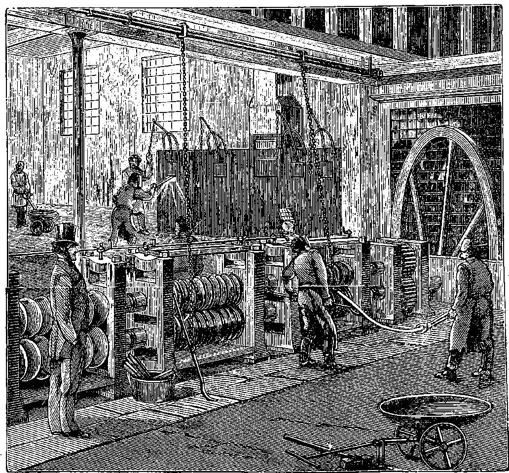
Fig. 26a.—Rolling Mill.
Fig. 26a shows a rolling mill with what is called a “two-high” train for finishing bars by passing them between the grooves cut in the rolls to give the required section. The rolls in the illustration turn in one direction only, and therefore the bars after emerging from the larger grooves have to be drawn back over the machine and set into a smaller pair from the same side. This inconvenience is avoided in the “three-high train,” on which three rolls revolve, and the bars can be passed through them from one side to the other alternately. The celerity with which a glowing steel ingot is without re-heating converted into a straight steel rail 60 or 100 feet long, by passing a few times backwards and forwards between the rolls, is very striking. These rolls are made of solid steel, and in some cases have a diameter of 26 inches or more.
72
IRON IN ARCHITECTURE.
Everyone knows how much iron is used in those great engineering structures that mark the present age, and of which a few examples will be described in succeeding articles. One other feature of the nineteenth century is the use of iron in architecture. Some have, indeed, protested against the use of iron for this purpose, and would even deny the name of architecture to any structure obviously or chiefly formed of that material. Stone and wood, they say, are the only proper materials, because each part must be wrought by hand, and cannot be cast or moulded; and further, iron being liable to rust, suggests decay and want of permanence, and these are characters incompatible with noble building. All this can rest only on a relative degree of truth—as, for instance, machinery is used to dress and shape both wood and stone, and the permanence of even the latter is as much dependent on conditions as that of iron. Iron used in architecture is hideous when applied in shapes appropriate only to stone; but when it is disposed in the way suggested by its own properties, and receives ornament suitable to its own nature, the result is harmonious and graceful, and the structure may display beauties that could be attained by no other materials. Be that as it may, the great and lofty covered spaces that are required for our railway stations and for other purposes could have been obtained only by the free use of iron, and everyone can recall to mind instances of such structure not devoid of elegance, in spite of the absence—the proper absence—of the Classic “orders” or Gothic “styles.” The first notable instance of the application of iron on a large scale was the erection of the “Crystal Palace,” in Hyde Park, for the great Exhibition of 1851. It was taken down and re-erected at Sydenham, and there it has become so well known to everyone that any description of it is quite unnecessary in this place.
As another conspicuous example of what may be done with iron, the Eiffel Tower at Paris may be briefly described.
The idea of erecting a tower 1,000 feet high was not of itself new. It had been entertained in England as early as 1833, in America in 1874, and in Paris itself in 1881. It has been reserved for M. Gustave Eiffel, a native of Dijon, who commenced to practise as an engineer in 1855, to realize this ambitious project. He has long been occupied in the construction of great railway bridges and viaducts, and in these he has adopted a system peculiar to himself of braced wrought-iron piers without masonry or cast-iron columns. He also was the first French engineer to erect bridges of great span without scaffolding. In the Garabit viaduct he planned an arch of 541 feet, crossing the Truyère at a height of nearly 400 feet above it. One result of M. Eiffel’s studies in connection with these lofty piers was his proposal to erect the tower for the Paris Exhibition of 1889. This proposal met with great opposition on the part of many influential people in Paris—authors, painters, architects, and others protesting with great energy against the modern Tower of Babel, which was, as they said, to disfigure and profane the noble stone buildings of Paris by the monstrosities of a machine maker, etc. etc. The Eiffel Tower is now constructed, and no one has heard that it has dishonoured the monuments of Paris, for it has been instead a triumph of French skill, the glory of its designer, and the wonder of the Exhibition.
73
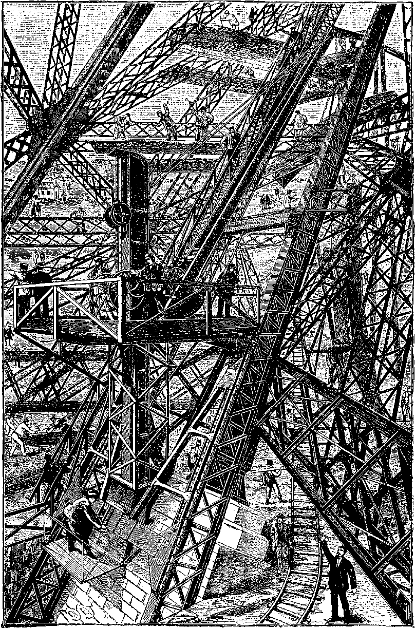
Fig. 26b.—The Eiffel Tower in course of construction.
The tower rests on four independent foundations, each at the angle of a square of about 330 feet in the side, and it may be noted that the two foundations near the Seine had to be differently treated from the other two, where a bed of gravel 18 feet thick was found at 23 feet below the 74surface, and where a bed of concrete, 7 feet thick, gave a good foundation. The foundations next the river had to be sunk 50 feet below the surface to obtain perfectly good foundations. Underlying the whole is a deep stratum of clay; but this is separated from the foundations by a layer of gravel of sufficient thickness. Above this are beds of concrete, covering an area of 60 square metres, and on the concrete rests a pile of masonry. Each of the four piles is bound together by two great iron bars, 25 feet long and 4 inches diameter, uniting the masonry by means of iron cramps, and anchoring the support of the structure, although its stability is already secured by its mere weight. The tower is of curved pyramidal form, so designed that it shall be capable of resisting wind pressure, without requiring the four corner structures to be connected by diagonal bracing. The four curved supports are, in fact, connected with each other only by girders at the platforms on the several stages, until at a considerable length they are sufficiently near to each other to admit the use of the ordinary diagonals. The work was begun at the end of January, 1887, and M. Eiffel notes how the imagination of the workmen was impressed by the notion of the vast height of the intended structure. Not steel, but iron is the material used throughout, and the weight of it is about 7,300 tons, without reckoning what is used in the foundations, and in the machinery connected with the lifts, etc. It has long ago been found that stone would be an unsuitable material for a structure of this kind, and it is obvious that only iron could possibly have been used to build a tower of so vast a height and within so short a space of time, for it was completed in April, 1889. A comparison of heights with the loftiest stone edifices may not be without interest. The highest building in Paris is the dome of the Invalides, 344 feet; Strasburg Cathedral rises to 466 feet; the Great Pyramid to 479 feet; the apex of the spire in the recently completed Cathedral at Cologne to 522 feet. These are overtopped by the lofty stone obelisk the Americans have erected at Washington, which attains a height of more than 550 feet. Such spires and towers have been erected only at the cost of immense labour. But iron, which can be so readily joined by riveting, lends itself invitingly to the skill of the constructor, more particularly by reason of the wonderful tensile strength it possesses. It is scarcely possible to convey any adequate idea of the great complicated network of bracings by which in the Eiffel Tower each standard of the columns is united to the rest to form one rigid pile. The horizontal girders unite the four piers in forming the supports of the first storey some 170 feet above the base. The arches which spring from the ground and rise nearly to the level of these girders are not so much intended to add to the strength of the structure as to increase its architectural effect. The first storey stands about 180 feet above the ground, and is provided with arcades, from which fine views of Paris may be obtained. Here there are spacious restaurants of four different nationalities. And in the centre of the second storey (380 feet high) is a station where passengers change from the inclined lifts to enter other elevators that ascend vertically to the higher stages of the tower. On the third storey, 900 feet above the ground, there is a saloon more than 50 feet square, completely shut in by glass, whence a vast panorama may be contemplated. Above this again are laboratories and scientific observatories, and, crowning all, is the lighthouse, provided with a system of optical apparatus for projecting the rays from a powerful electric light. This 76light has been seen from the Cathedral at Orléans, a distance of about 70 miles.
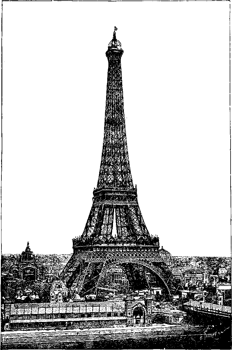
Fig. 26c.—The Eiffel Tower.
The buildings of the Paris Exhibition of 1889 are themselves splendid examples, not only of engineering skill, but of good taste and elegant design in iron structures and their decorations. The vast Salle des Machines (machinery hall) exceeds in dimensions anything of the kind in existence, for it is nearly a quarter of a mile long, and its roof covers at one span its width of 380 feet, rising to a height of 150 feet in the centre. This great hall is to remain permanently, as well as the other principal galleries with their graceful domes.
The Eiffel Tower having proved one of the most striking features of the great Paris Exhibition, and of itself a novelty sufficient to attract visitors to the spot, and having, long before the Exhibition closed, completely defrayed the expense of its construction, with a handsome profit besides, its success has naturally provoked similar enterprises,—as, for instance, at Blackpool, a seaside resort in Lancashire, there has been erected an openwork metal tower, resembling the Paris structure, but of far less altitude.
Tall Buildings in American Cities.
In several of the great cities of the United States, the last few years have witnessed a novel and characteristic development of the use of iron in architecture. In many structures on the older continent, this material has been frankly and effectively employed, forming the obvious framework of the erection, even when the leading motive was quite other than a display of engineering skill. The Crystal Palace at Sydenham and other erections have been referred to, in which iron has taken its place as the main component of structures designed more or less to fulfil æsthetic requirements: the guiding principle in “tall office buildings” in the cities of the Western continent is, on the contrary, avowedly utilitarian. Iron has, of course, long been used in the form of pillars, beams, etc., in ordinary buildings, and it is only the extraordinary extension of this employment of it, after the lift or elevator had been perfected, and the ground-space in great commercial centres was daily becoming more valuable, that has led to the erection of structures of the “sky-scraper” class in American cities. For a given plot at a stated rent, a building of many stories, let throughout as offices, will obviously bring to its owner a greater return than one of few stories. The elevators now make a tenth story practically as accessible as a third storey, and the tall building readily fills with tenants. No claim for artistic beauty has been advanced for these structures, which aim simply at being places of business, and if provision be made for sufficient floor-space and daylight, and for artificial lighting, heating, and ventilation, together with the ordinary conveniences of modern life, and ready elevator service, nothing more is required by the utilitarian spirit, that seeks only facilities for money-getting. These tall buildings are usually erected on plots disproportionately small, and the architectural effect is apt to be bizarre and incongruous, especially when the structure shoots up skyward in some comparatively narrow street amid more modest surroundings. They are really engineering structures, but invested with features belonging to edifices of quite another order of construction. If they are necessities of the place and period, and are “come to stay,” it cannot be doubted but that decoration of an appropriate 78and harmonious character will, in course of time, be evolved along with them, when the conventionality that clings to architecture shall be broken through, and a new style appear, as consistent, and therefore as beautiful, in relation to the “tall office building,” as were those of the Greek temple and the Gothic minster in their free and natural adaptation.
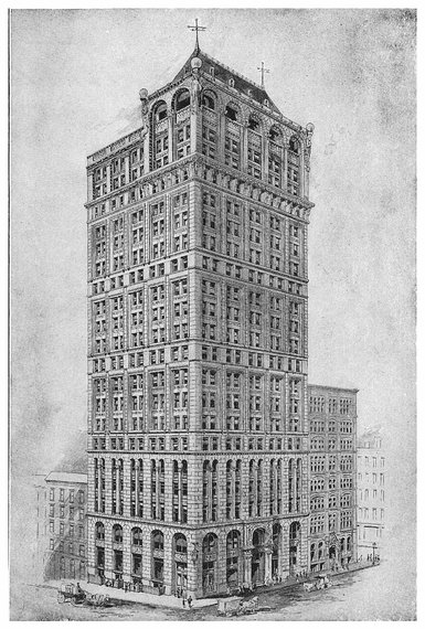
PLATE IV. THE AMERICAN TRACT SOCIETY BUILDING.
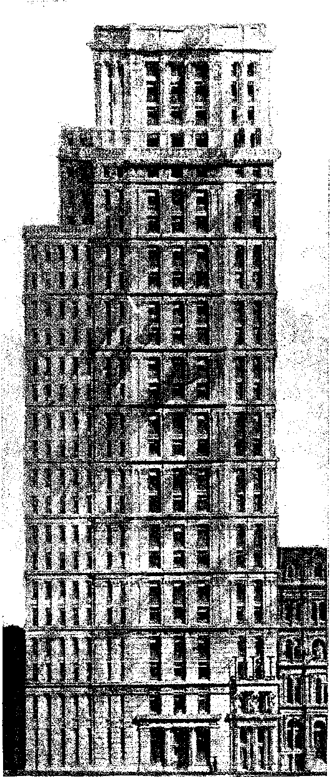
Fig. 26d.—St. Paul Building, N. Y.
Here, apparently, is the opportunity for the advent of a new and characteristic style. There is great ingenuity displayed in the arrangement and internal finish of these buildings. But besides the somewhat novel application of iron, the most notable circumstances regarding them are the tendency to make them of greater and greater height, and the wonderfully short time in which, upon occasion, they can be run up. Chicago has recently been noted for its tall edifices, among which may be named The Reliance Building, erected upon a site only 55 feet in breadth, but rising in fourteen stories to the height of 200 feet, and presenting the appearance of a tower. There are no cast iron pillars, but the whole metal framework is of rolled steel, the columns consisting of eight angle-sections, bolted together in two-story lengths, adjoining columns breaking joint at each floor, and braced together with plate girders, 24 inches deep, bolted to the face of the columns, with which they form a rigid connection. Externally, the edifice shows nothing but white enamelled terra-cotta and plate glass. This building was originally a strongly-built structure of five stories, the lower one being occupied as a bank. The foundations and the first story were taken out, and prepared for the lofty edifice, the superstructure being the while supported on screws. Then the three upper stories were taken down, and the building was continued from the second story, which was filled with tenants while the building was in course of erection above.
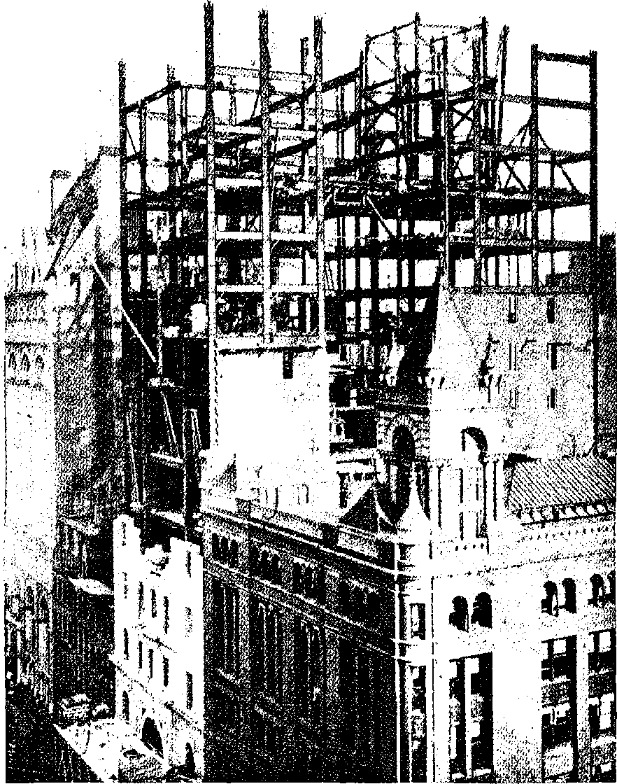
Fig. 26e.—Manhattan Insurance Co.’s Building, in course of erection.
Still more lofty edifices have been going skyward in other places. Already in New York there are a great number of lofty piles due to the introduction of the lifts or elevators, by which an office on the tenth floor is made as convenient as one on the second. These buildings usually receive the name of the owners of the structure, who occupy, perhaps, only one floor. To mention only a few. There is the American Tract Society building, with its twenty-three stories, 285 feet high, which is one of the latest and handsomest of these tall piles in the city. See Plate IV. Still loftier is the St. Paul building, fronting the New York Post-Office at the junction of Park Row and Broadway. This structure is splayed at the angle between Ann Street and Broadway, where its width is 39½ feet, while its loftiest part has frontages of about 30 feet along each of these thoroughfares. The height is no less than 313 feet above the pavement, and the number of stories is twenty-five. This building is faced with light yellow limestone, and although it was commenced only in the summer of 1895, it was expected to be ready for occupation by the autumn of 1896. Even this great height is overtopped by the Manhattan Life Insurance Company’s building, rising 330 feet, and remarkable as perhaps beyond previous record of quickness in building a gigantic structure. Obviously, the foundations of such a building must be most seriously considered, prepared and tested, before the great bulk of the building is begun, and in the New York Engineering Magazine one of the architects has given a full account, with complete illustrations, of all the works, from the rock foundation to the completed edifice. A description of the foundation work, though most interesting for the professional engineer, would probably have little attraction for the general reader; 79but its importance may be inferred from the fact of its having taken nearly six months for its completion, while the huge superstructure required only eight months. The eighteenth tier of beams was reached in “three months from the time the foundations were ready on which to set the first piece of steel, composing the bolsters that support the cantilever system.... The substructure, which starts in bed-rock and continues to the cellar-floor, consists of fifteen piers, varying in size from 9 feet in diameter, to 21 feet 6 inches by 25 feet square.... The number of bricks used in the piers amounted to 1,500,000. From this it may be seen that a good-sized building was sunk out of sight before any part of the superstructure could be begun.” An open court within the main structure, special framing for the arrangements of the company’s offices on the sixth floor, the great height and weight of the tower, and the requisite provision for wind-bracing, delayed in some degree a regular advance of the stories; 80but within three months no less than 5,800 tons were placed in position. There were girders weighing 40 tons, many columns of 10 and 12 tons, and cantilevers of 80 tons weight and 67 feet long. Strange to say, that in a building of this magnitude, where such masses had to be raised 300 feet into the air, there was not a single accident involving loss of life. When four stories of the steel framework had been put up, the bricklayers were set to work, and they followed the frame-setters throughout. After the masons came the pipe-layers, with their ten miles of pipes, followed by electricians, fixing their thirty-five miles of communicating wires. Thirty thousand cubic feet of stone was cut and set on the Broadway front in eighty days. Then craftsmen of the different trades followed each other, or worked in harmony together, story after story upwards: the engineers for boilers, heating, and elevators, the plumbers, the decorators, the carpenters and cabinet-makers, the plasterers, the marble and tile workers, 81the gasmen, etc. In fine, every story was completely finished and ready for occupation in eight months after the start from the foundations.
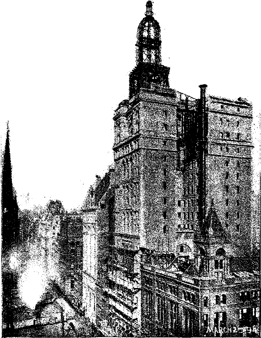
Fig. 26f.—Manhattan Insurance Co.’s Buildings nearly completed.
The shortness of the time in which these lofty buildings were run up is not less remarkable than the completeness of their fittings, which comprise everything requisite for communication within the premises and in connection with the outer world. The elevators or lifts are the perfection of mechanism in their way, and act with wonderful smoothness and regularity; of these are usually two at least, as well as an ample staircase. Notwithstanding all these appliances, some disastrous and fatal conflagrations have occurred at buildings erected on the “tall” principle; and as “business premises” of even 380 feet high are projected, the authorities have been considering the desirability of restricting the heights. It has been proposed that offices should not exceed in height 200 feet; hotels, 150 feet; and private houses, 75 feet.
BIG WHEELS.
The Paris example of an engineering feat upon an unprecedented scale having proved sufficiently captivating for the general public to ensure for itself a great commercial success, even amid the attractions of an International Exhibition, was not lost upon the enterprising people of the States when the “World’s Fair” at Chicago was in preparation in 1893. It was then that Mr. G. W. G. Ferris, the head of a firm of bridge constructors at Pittsburg, conceived the idea of applying his engineering skill to the erection of a huge wheel, revolving in a vertical plane, with cars for persons to sit in, constituting, in fact, an enormous “merry-go-round,” as the machine once so common at country fairs was called. The novelty of the Chicago erection was, therefore, not the general idea, but the magnitude of the scale, which, for that reason, involved the application of the highest engineering skill, and the solution of hitherto unattempted practical problems. Several thousand pounds were, in fact, expended on merely preliminary plans and designs. The great wheel at Chicago was 250 feet in diameter, and to its periphery were hung thirty-six carriages, each seating forty persons. At each revolution, therefore, 1,440 people would be raised in the air to the height of 250 feet, and from that elevation afforded a splendid prospect, besides an experience of the peculiar sensation like that of being in a balloon, when the spectator has no perception of his own motion, but the objects beneath appear to have the contrary movement, that is to say, they seem to be sinking when he is rising, and vice versâ. The axle of the Chicago wheel was a solid cylinder, 32 inches in diameter and 45 feet long; on this were two hubs, 16 feet in diameter, to which were attached spoke rods, 2½ inches in diameter, passing in pairs to an inner crown, which was concentric with the outer rim, but 40 feet within it. The inner and outer crowns were connected together, and the former joined to the crown of the twin wheel by an elaborate system of trusses and ties, which, however, left an open space between the rims of 20 feet from the outside. These last were formed of curved riveted hollow beams, in section 25½ inches by 19 inches, and between them, slung upon iron axles through the roofs, were suspended, at equal intervals, the thirty-six carriages, each 27 feet long, and weighing 13 tons without its passengers, who added 3 tons more to the weight. The wheel with its passengers was calculated to weigh about 831,200 tons, and it rested on two pyramidal skeleton towers of ironwork 140 feet high, having bases 50 feet by 60 feet. The wheel was moved by power applied at the lowest point, the peripheries of both the rims having great cogs 6 inches deep and 18 inches apart, which engaged a pair of large cog-wheels, carried on a shaft 12 inches in diameter.
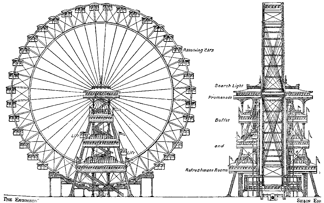
Fig. 26g.—Original Design for the Great Wheel.
This curious structure was not begun until March, 1893, yet it was set in motion three months afterwards, having cost about £62,500. The Company had to hand over to the Exhibition one half of the receipts after the big wheel had paid for its construction, but even then they realised a handsome profit, and at the close of the World’s Fair, they sold the machine for four-thirds of its cost, in order that it might be re-erected at Coney Island.
No sooner had the great Ferris wheel at Chicago proved a financial success than an American gentleman, Lieutenant Graydon, secured a patent for a like machine in the United Kingdom; and as it has now become almost a matter of course that some iron or steel structure, surpassing everything before attempted, should form a part of each great exhibition, a Company was at once formed in London, under the title of “The Gigantic Wheel and Recreation Towers Co., Limited,” to construct and work at the Earl’s Court Oriental Exhibition of 1895, a great wheel, similar in general form to that of Chicago. But the design of the London wheel had some new features, as will be seen from the sketches, Fig. 26c (from The Engineer of 20th April, 1894), and, moreover, having been planned of larger dimensions than its American prototype, presented additional engineering problems of no small complexity. After due deliberation the scheme of the work was entrusted to Mr. Walter B. Basset, a talented young engineer, connected with the firm of Messrs. Maudslay, Sons, & Field, and already experienced in designing iron structures. Under this gentleman, with the assistance of Mr. J. J. Webster in carrying out some of the details, the work has been so successfully accomplished that the “Great Wheel” of 1895 may be cited as one of the crowning mechanical triumphs of the nineteenth century. The original design has not been followed so far as regards the lower platforms for refreshment rooms, &c. Plate V., for which we are indebted to Mr. Basset, is a photographic representation of the actual structure.
The wheel at Earl’s Court exceeds the Ferris wheel in diameter by 50 feet, being 300 feet across. It is supported on two towers, 175 feet high, each formed by four columns 4 feet square, built of steel plates with internal diaphragms, and surmounted by balconies that may be ascended in elevators raised by a weight of water, which, after having been discharged into a reservoir under the ground level, is again pumped up to the top of the towers. Between the balconies on each tower there is also a communication through the axle of the wheel, which, instead of being solid as at Chicago, is a tube of 7 feet diameter, and 35 feet long, made in sections, riveted together, of steel 1 inch thick, and weighing no less than 58 tons. The raising and fixing in its high place of such a mass of metal required specially ingenious devices, which have been greatly appreciated by professional engineers. But for these devices, the erection of scaffolding in the ordinary way of proceeding would have entailed an outlay simply enormous. The axle is stiffened by projecting rings, and, between pairs of these, the spoke rods are attached by pins 3 inches in diameter. The axle was the production of Messrs. Maudslay, Field & Co.; all the rest of the metal work was made at the Arrol Works at 84Glasgow, and the carriages were constructed by Brown, Marshall & Co., of Birmingham. The Earl’s Court wheel is turned by a mechanism different from that of the Chicago wheel, for whereas the latter was provided with cogs, the former has two chains, each 1,000 feet long and 8 tons weight, surrounding the periphery of the wheel on either side. The chains go over drums in the engine-shed, from which they pass underground to guide-pulleys, and as they unwind from the Great Wheel, they again go over guide-pulleys to lead them back to the drums. These chains are firmly held throughout in the jaws of V-shaped grooves, and there are arrangements for taking up the slack. The drums are actuated by wheel gearing, connected with two horizontal Robey steam engines, each of 50 horse-power, one on either side, capable of being worked singly or together. It is, however, found sufficient to use the engine of one side only, and even then to work it at but 16 horse-power, and the operation can be controlled by one man, who has also the command of a brake. Both starting and stopping are accomplished with the greatest smoothness and absence of strain or jar. There are forty carriages, each 25 feet long, 9 feet wide, and 10 feet high. Each will accommodate forty passengers, and these enter at the ends from eight platforms at different heights from the ground, so arranged as to be on the level of the eight lowest carriages while the wheel is stationary. The passengers who have had their ride leave at the other end of the carriages by eight similar platforms on the other side of the wheel. After the change of passengers in one set of eight carriages, the wheel is turned through exactly one-fifth of a revolution, which has the effect of bringing the next eight carriages to the level of the platforms, and it is again brought to a standstill whilst the change of passengers is taking place; and so on, until the whole freight of say 1,600 persons has been changed during the five stoppages in one revolution, for which about thirty-five minutes are required, and the process of emptying and filling eight carriages at once is repeated. There are first and second class carriages, the charge for the former being two shillings, and for the latter one shilling; so that, reckoning 800 passengers of each class, one turn would bring to the treasury the handsome sum of £120.
The sensations experienced in a journey on the Great Wheel are, as already mentioned, comparable to those enjoyed by the aërial voyagers in a balloon, where all perception of proper motion is lost, and it is the world beneath that seems to recede and float away, presenting the while a strangely changing panorama. Many people who have never made a balloon ascent yet know the calm delight of floating in a boat without effort down some placid stream, unconscious of any motion beyond that vaguely inferred from the silent apparent gliding by of the banks. Very similar are, in part, the feelings of the passenger who is almost imperceptibly carried up into the air in a carriage of the Great Wheel, but the vertical direction of the movement, and the gradual expansion of the horizon as the vertex is approached, lend an unwonted novelty to the situation. From the Earl’s Court Wheel the view is both interesting and extensive, for on a clear day the prospect stretches as far as the Royal Castle of Windsor.
The “Gigantic Wheel” at Earl’s Court was inaugurated on the 11th July, 1895, in the presence of an assemblage of 5,000 people, including many distinguished personages, who were all treated to a ride. Plate I. shows a portion of the wheel and carriages as in motion.
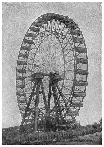
PLATE V. GENERAL VIEW OF THE GREAT WHEEL AT EARL’S COURT.
85
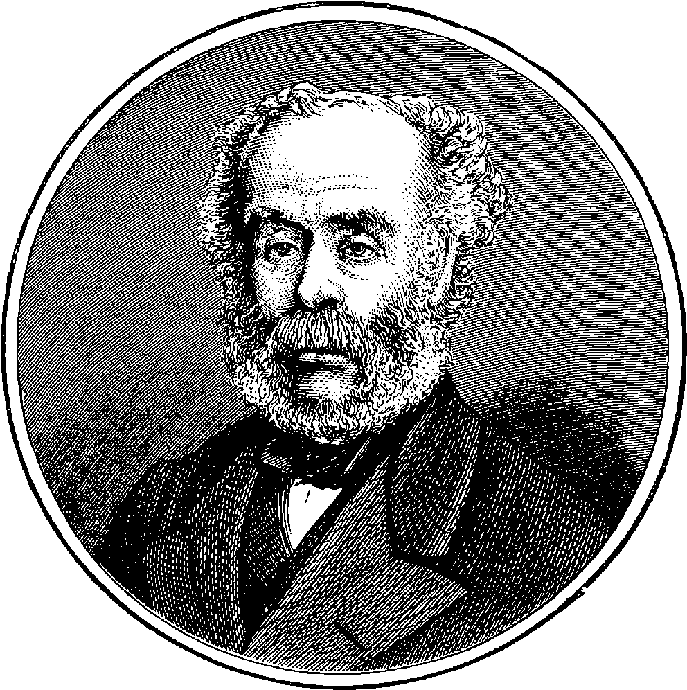
Fig. 27.—Sir Joseph Whitworth.