ELECTRICITY. (continued 2)
Reading edition
The Gramme machine has also been ingeniously employed for railway brakes on some of the Belgian lines; and it is applicable to telegraphy, where the cost of zinc, acids, batteries, &c., is a considerable item. It is 519impossible to predict the many applications for manufacturing purposes which will be made of electricity, now a cheap, reliable, and convenient mode has been discovered of producing currents of any required strength. Though by no means the first or only machine by which mechanical force can be converted into dynamical electricity, it shows an immense advance on any former one in the regularity of the action, and in the capability of being driven at a very high rate of speed without the inconvenient accompaniments of the heating of the conductors and destructive sparks at the movable contacts. There can be no doubt of the importance of this machine for use in lighthouses, and for metallurgical and chemical purposes, and the inventor believes the time will come when all large ocean-going vessels will carry an electric light at the masthead. The light would be sufficiently powerful to show rocks or land five or six miles ahead, and an additional safeguard of incalculable value would be thus provided for those “that go down to the sea in ships, that do business in great waters.”
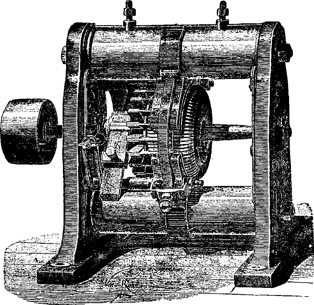
Fig. 280.
ELECTRIC LIGHTING AND ELECTRIC POWER.
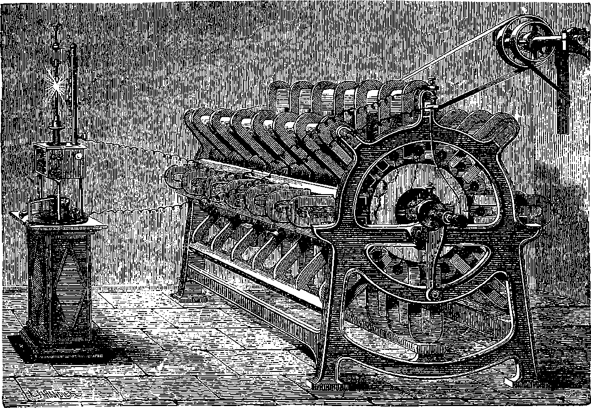
Fig. 280a.—The Alliance Machine.
It was mentioned in the last section that the introduction of so convenient and reliable a means of producing electrical currents as the Gramme machine, would cause electricity to be largely applied for illuminating and other purposes. The Gramme machine was first made in 1870, and it attracted much attention, as the principle of combining the currents was quite different from that used in previous magneto-electric 520machines. In fact, the Gramme machine yielded quite unexpected results, and the principle employed in it opened a new field. The development that has taken place in the applications of electricity within the twenty years since 1870 has been truly marvellous. The electric light appears to have been first used in lighthouses about 1862, and the machines by which the current was produced were, in principle, combinations of a great number of Clarke’s machines (see page 509). One such machine was invented by Mr. Holmes, and was used for the illumination of the South Foreland Lighthouse in 1862. Another similar form of still earlier invention had been set up in Paris as early as 1855,—not, indeed, for the purposes of illumination, but for a project which failed. Its arrangement had been originally suggested by a Belgian physicist in 1849; and the machine of 1855, having received certain improvements, afterwards became very well known by the name of the Alliance Company’s machine, or simply the Alliance machine. It is represented in its improved form in Fig. 280a. Here ranges of steel horse-shoe magnets will be observed, each magnet weighing about 40 lbs. and made of six plates of tempered steel, held together with screws. Each of the eight rows of magnets contains seven, and thus sixteen poles are presented at uniform distances, arranged in circles. Carried on the central axle are six discs, which revolve between the circles of sixteen poles, and on the circumference of each disc are sixteen equidistant bobbins or coils of insulated wire, so that the whole of the sixteen coils are opposite to the sixteen poles at the same moment. The extremities of the wires at the coils are connected with proper 521adjustments for gathering up the currents, and by means of these the coils may be arranged either for tension or for quantity, like the elements of a battery (page 494).
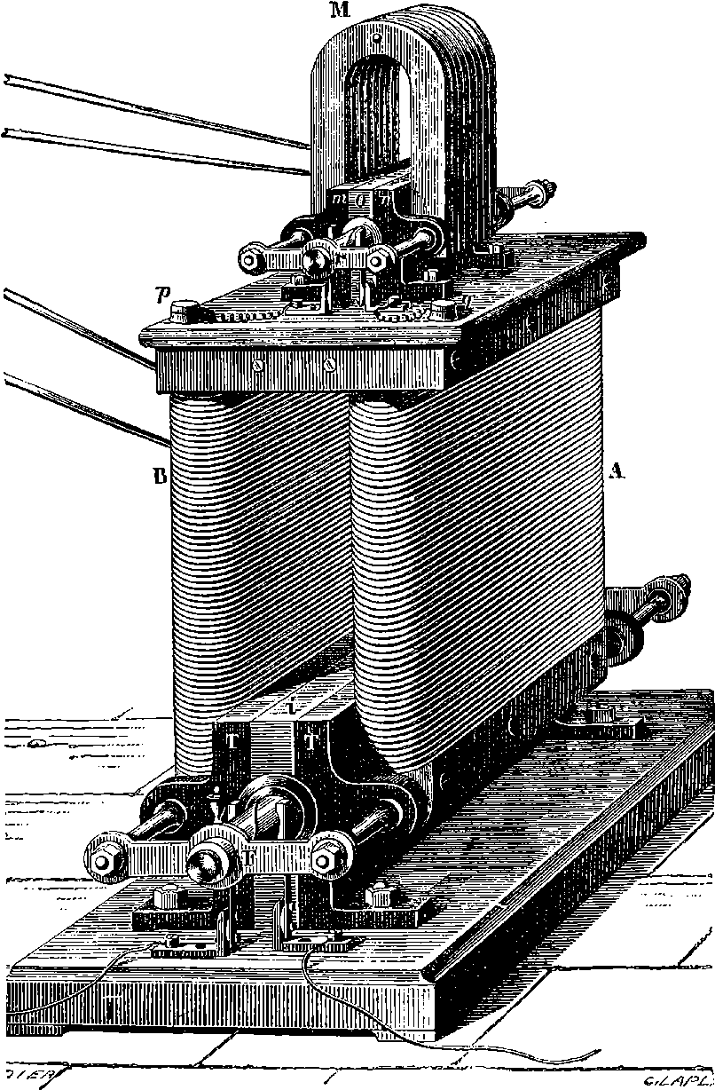
Fig. 280b.—Wilde’s Machine.
Wilde’s machine, which has been mentioned in page 511, is shown in fig. 280b. It will be observed that this consists of a small machine, M, with permanent steel magnets, and the current from these circulates through the coils of the electro magnets, A B. The arrangement of the armatures, bobbin, commutators, etc., is the same in both cases. But as a speed of 2,500 revolutions per minute was needed, it was necessary to 522keep the bearings, T T, from heating by causing cold water to circulate through them. Mr. Ladd arranged a machine on the same principle as Wilde’s, by suppressing the permanent magnets, but availing himself of the residual magnetism of the iron core to bring about the induction. A machine of this kind was shown at the Paris Exhibition of 1867, and people were quite astonished to see electrical power capable of producing a brilliant light developed by a small machine 2 ft. long, 1 ft. wide, and 9 in. high. But the great velocity of rotation, and the consequent heating of the bearings, left much to be desired before a really practical machine could be produced.
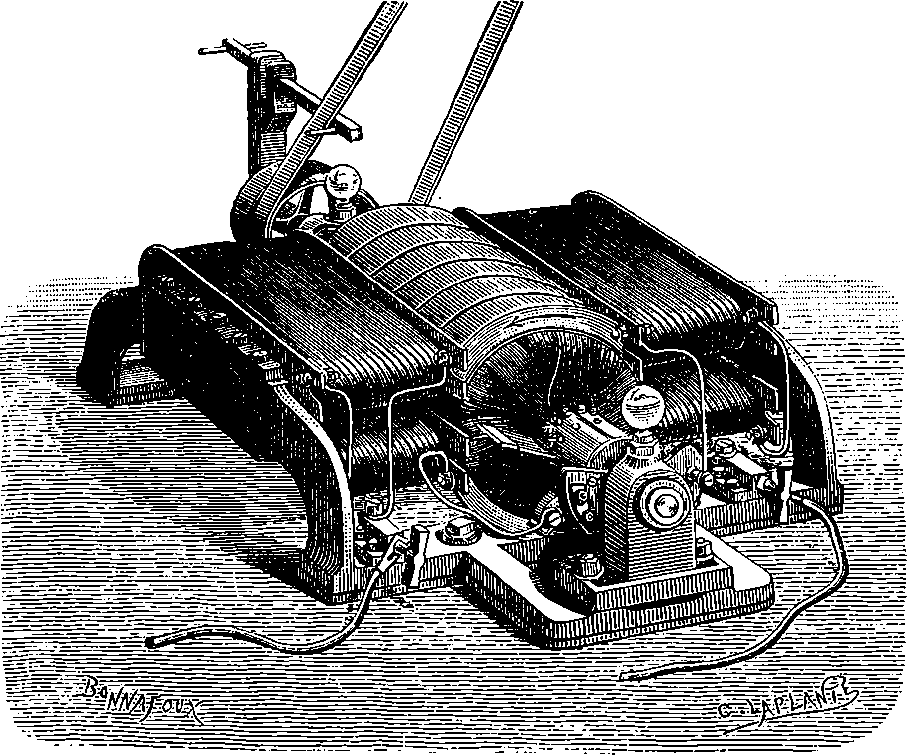
Fig. 280c.—Siemens’ Dynamo.
In the newest Siemens’ machine, represented in fig. 280c, the Gramme principle is made use of, as the revolving coil is of large diameter, and it consists of a copper cylinder, on which are wound a number of juxtaposed coils like those of a galvanometer. The revolving cylinder is surrounded by the poles of a system of electro-magnets excited by the whole of the induced current being passed through their coils. In a paper describing this machine, Siemens first made use of the term “dynamo-electric machine,” and this expression, contracted to the single word DYNAMO, has since been universally employed to designate machines of this kind. The modifications in the forms and arrangements of the different dynamos that have been invented in late years are endless, and every week patents are granted for further improvements and fresh combinations of the parts. It would be quite beyond the scope of this work to enumerate all the forms of the dynamo that have been favourably spoken of; but we shall content ourselves by adding a drawing of the Brush dynamo (Fig. 280d), which has been so largely used for electric lighting in the United States. In this dynamo we have a Gramme ring, but the number of coils on it is reduced 523to eight, the intervals being filled up with pieces of iron, and the ring revolves in a vertical plane between the poles of two double oblong electro-magnets, which are arranged with poles of the same name opposite to each other. The commutators shown in the nearer part convert the alternately reversed currents generated in the coils into a direct continuous one. They are formed with bundles of wires, as in the Gramme machine.
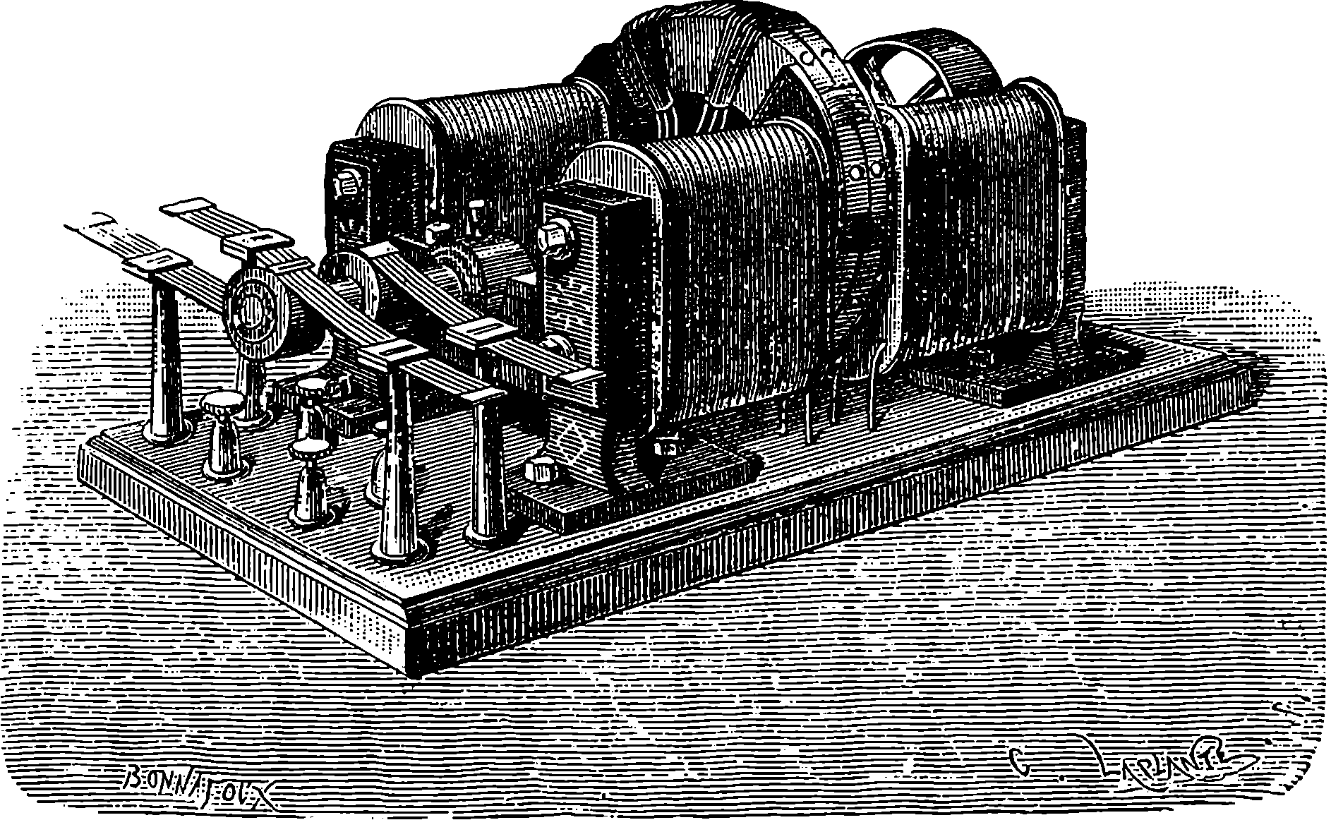
Fig. 280d.—The Brush Dynamo.
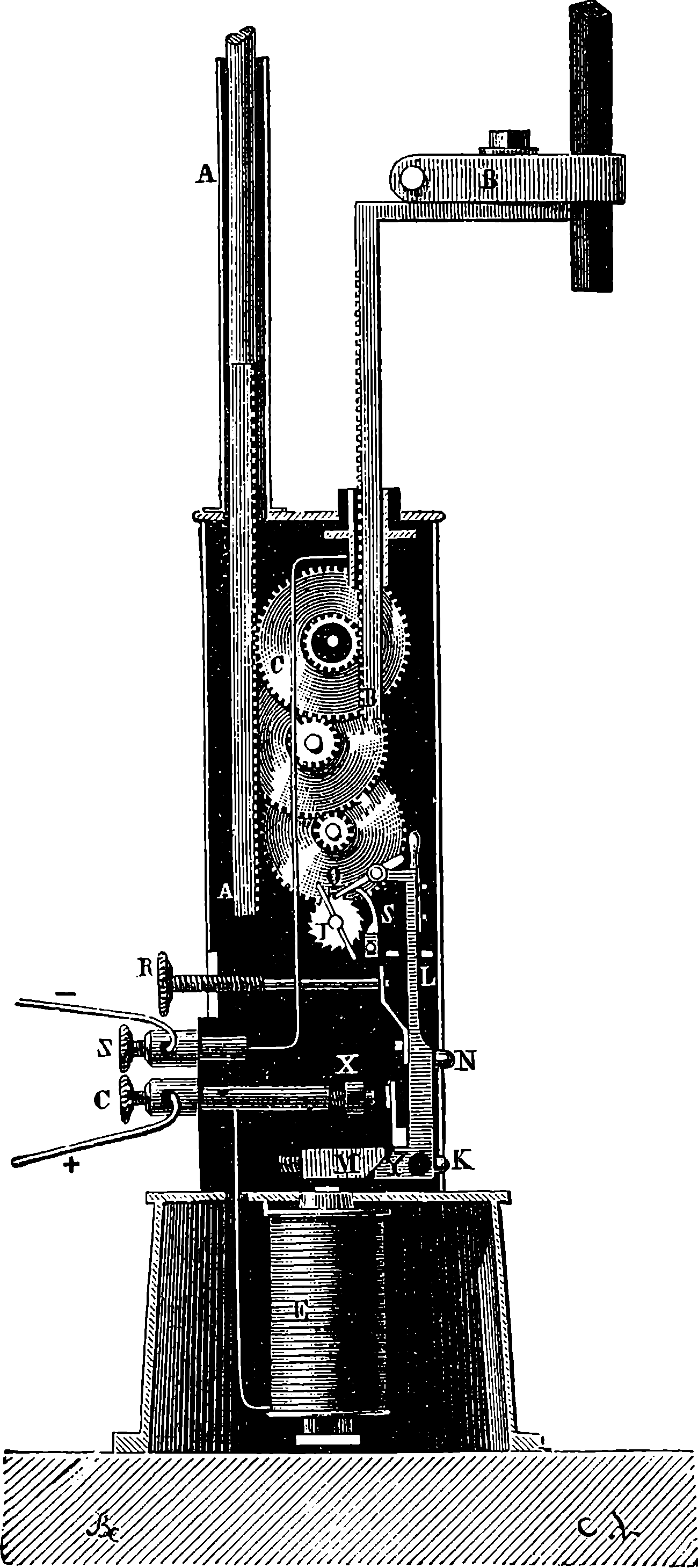
Fig. 280e.—Siemens’ Regulator.
But the providing of a cheap and efficient source of current electricity, although an absolutely necessary step, would not have been capable of bringing about the present development of electric lighting, unless the appliances by which the current is made to manifest itself as light had not also been brought nearly to perfection. The conditions required to maintain a steady light from a current of electricity passing between carbon points have been already explained on page 497, and a representation of Dubosc’s electric lantern and regulator is shown. The regulator systems that have been invented since it became obvious that the light of the electric arc admitted of practical application on the large scale are very numerous. The earlier forms of regulator, which were used only for scientific purposes—such as lantern projections on screens, experiments on light, etc.—were complicated in their arrangements and uncertain in their action, for great variations in the light sometimes took place, and occasionally it would, indeed, be extinguished, and then again shine out as brightly as before. Nearly all the regulators that have come into use depend upon movements controlled by electro-magnetic actions produced automatically as the distance between the carbon changes. It would, however, lead us too far into the technicalities of the subject to explain minutely the mechanism of any particular form of the mechanical regulators, and the results depend so often upon the minute details, that it would be difficult to trace the action without a set of large and complete drawings. Perhaps the regulators that have been most used are those of Serrin, Siemens, Brush, Thomson, Houston and Edison. But nearly every inventor has produced different forms of his apparatus; Siemens, for instance, has patented eight or ten regulators. Fig. 280e shows the mechanism of one of the last named inventor’s regulators, in which the 524two actions required for the separation and approach of the carbons are determined respectively by the vibrations of the rocking lever, M Y L, actuated by the electro-magnet, E, and the simple weight of the upper carbon-holder, A A. When the lamp is not in circuit, the lever, L, is thrown back by a spring, the tension of which is regulated by the screw, R, so that the catch, Q, is disengaged from the wheel, I. The train of wheels is then free to revolve by action of the rack, A, supporting the weight of the upper carbon, until the motion stops by the carbons touching each other. Now let the lamp be connected up, and the current will pass from C, through the electro-magnet, the mass of the apparatus, and return by the wire connecting the lower carbon-holder with Z. The carbon points will glow, but the magnet then attracting M moves the lever, L, the piece, Q, engages the wheel I, pushing it one tooth forward. But this movement of the lever establishes a contact at X, so that the current abandons the electro-magnet, to pass the shorter way, and M being no longer attracted, the lever is pushed back by the spring, the contact at X is broken, and the magnet being again excited the lever turns as before, and Q pushes I round the space of another tooth. These alternating actions succeed each other with great rapidity, and effect the separation of the carbons through the train of wheels acting on the racks. These movements continue until, in a second or two, the separation of the carbons has become so great, that the current passing through the electro-magnet is no longer able to operate against the weight of the upper carbon-holder, and this happens when an arc of proper size is produced, this required result being brought about by proper adjustment of the parts of 525the apparatus, marked by the letters R, K and X. But as the carbons are consumed, the increase of the length of this arc further weakens the current, until the spring attached to the lever, L, prevails over the attractive force of the electro-magnet on M, and thus withdraws the catch, Q, altogether, when the wheels being free to turn, the weight operates to bring the carbons nearer together, until, with the lessened resistance, the energy of the current is restored, and Q again comes into play to arrest the approximating movement. It may be seen, from the above explanation, that this lamp is automatic; in other words, when it has once been properly adjusted, it is lighted by merely completing the circuit. For fixing the carbons properly in their holders there are, of course, other regulating screws. How very nearly perfection the automatic regulation of the arc electric lamp has been brought by such contrivances as these, will be obvious to all who have noticed the steadiness that has been attained in all the modern installations.

Fig. 280f.—Jablochkoff Candle.
An ingenious plan was devised by Jablochkoff for dispensing with all mechanism for regulating the distance of the carbons. This invention is known as the electric candle, and is of great interest from the fact that it was with this arrangement that the electric light was, for the first time, practically employed for street and theatre illumination. This was in 1878, when visitors to Paris, during the Exhibition, were astonished by the splendid displays in the Avenue de l’Opéra, at the shops of the Louvre, and at some of the theatres. Then it was shown, for the first time, that electric lighting was not merely a scientific curiosity, but a new and formidable rival to gas. The Jablochkoff candles were also subsequently used in the electric lamps on the Thames Embankment. The principle of the contrivance will be understood from fig. 280f. Two carbons, C and D, are placed parallel at a little distance apart, and the space between them is filled up with plaster of Paris, kaolin, or some similar material, through which the current will not pass, but which burns, fuses, volatilises, or crumbles away by the heat produced by the passage of the current between the two carbons. These carbons are, of course, fixed in insulated holders, and to start the candle a small tip of carbon paste is made to connect the carbons at the top. The Jablochkoff candles must be used with currents rapidly alternating in direction. The reason for this is, that otherwise one of the carbons (the positive one) would be consumed quicker than the other, and that would cause the distance between them to increase, until it became so great that the current would cease to pass, and the light would go out. In order to obtain such alternating currents with the Gramme machine, a special apparatus had to be devised to change its direct into alternately reversed currents; but, dynamos intended to supply electric lights are now made without commutators, and they supply rapidly succeeding currents in opposite directions. In certain types of dynamos, again, the armature coils are stationary, and it is the field magnets that are made to revolve, and in these cases, not even a sliding contact is required, but the end of the armature coils are directly and permanently connected with the main circuit. But as these dynamos are self-exciting, the electricity induced in a few of the armature coils is collected apart 526from the main circuit, and passed through the electro-magnets of the machine itself, after the alternate currents have, by means of a commutator, been converted into one direct continuous current.
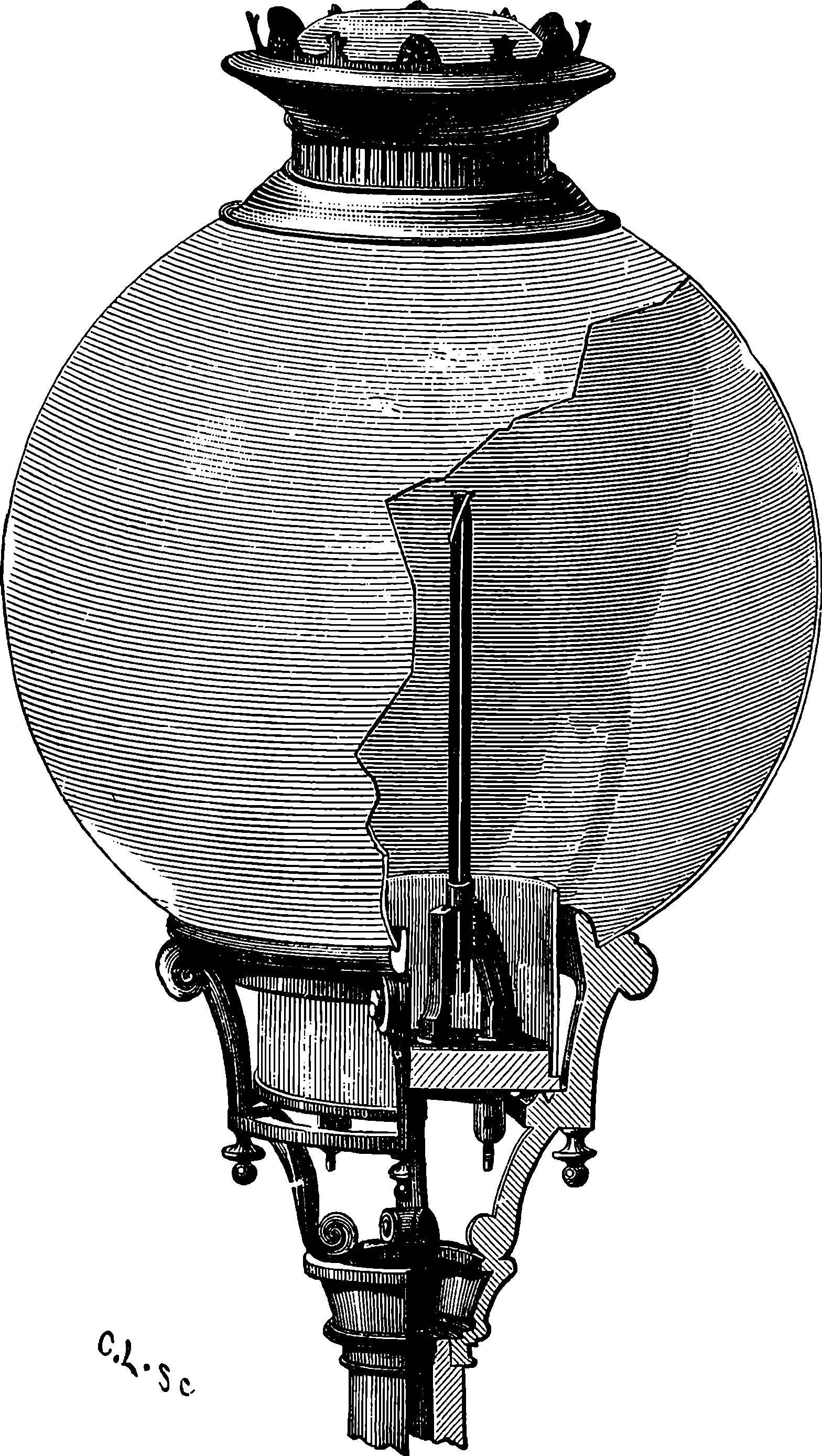
Fig. 280g.—Electric Lamp.
The arc electric light, as used for the illumination of streets and public places, is too intense and concentrated to be pleasant to the eye, and therefore it has been found necessary to surround it by globes of enamelled glass, or of porcelain, or of ground glass, or of frosted glass. By these expedients for diffusing and softening the light, it is rendered much more acceptable, but this advantage is gained at the cost of a considerable loss of the whole illuminating power, a loss which is, probably, never less than 10 per cent., but is usually much greater. The globes used in Paris, with the Jablochkoff candles, were of enamelled glass, and the apparatus was arranged, as shown in Fig. 280g, where it is partly represented in section, and with a part of the globe broken off, in order to show one of the candles placed in the holder which connects it with the circuit. In each lamp several candles were mounted, in some cases four; but the lamps in the Place de l’Opéra held twelve. At first there were mechanical arrangements, automatic and otherwise, by which, when the candle was burned down the current could be turned on to another. But M. Jablochkoff afterwards discovered that there was really no need for such a mechanism. For when the whole of the candles are simultaneously and equally connected with the circuit conductors, it is found that one of them will 527more easily transmit the current than any one of the rest, and when that particular one has once been lighted by the heat developed, the current will pass almost entirely through the arc, any loss through the connecting strip of carbon, at the tops of the other candles, being quite insignificant. When the first of the candles has burnt down completely, until the insulating porcelain holder separates the carbons, the current will at once re-establish itself at the top of one of the remaining carbons, and so on, while one is left.
The arc electric light has not been brought to its present position without the expenditure of much care and ingenuity in the preparation of the carbons used for its production. When Davy first produced the voltaic arc, the electrodes he used were simply sticks of charcoal. These were very quickly consumed, and a more durable form of carbon was sought for. This was found by Foucault, who made use of rods sawn out of the carbonaceous residue left in the retorts in the process of making coal-gas. This substance was, however, by no means uniform or sufficiently pure, and the light obtained was consequently unsteady. Many experiments were made in preparing special carbons. Pounded coke, coke and charcoal, were mixed with syrup or tar into a paste, which was moulded and compressed, and then the sticks were kept in covered vessels at a high temperature for many hours. Acids were used for purification, and also alkalis, to remove silica. At the present time there are several manufacturers of electric light carbons who carry on extensive operations by processes which probably are very similar one to another, and which may well be represented by M. Carré’s, whose carbons have the highest reputation. M. Carré prefers a mixture of powdered coke, calcined lampblack, and a syrup made of sugar and gum. The whole is well mixed and incorporated, water being added from time to time to make up for loss by evaporation, and to give the paste the proper degree of consistence. The paste is then subjected to compression, by which it is forced through draw-holes, and the carbons, having been piled up in covered crucibles, are exposed for a certain time to a high temperature.
As a practical illuminant for lighthouses, the arc electric light came into use many years ago (1862) as we have already seen. This was when the generator of the current was the magneto-electro machine; but, now, when this generator has developed into the modern dynamo, the cost of the electric supply has been enormously reduced, so that, power for power, electric lights may be worked at half the former cost, and with greater convenience and certainty. Light for light, electrical illumination is said to be far cheaper than gas. Again, the arc electric light has properties which have caused it to be employed, not only in every important lighthouse in England, France, Russia, America, and elsewhere, but most ships of war are provided with means of projecting a beam of electric light in any direction, in order that the presence of torpedo boats, etc., may be discovered at night, or harbours entered and signals made under circumstances when such operations would be otherwise impossible. It was by the use of the electric light that, in 1886, one of the Peninsular and Oriental Company’s steamers passed safely through the Suez Canal, at night, and the experiment was so satisfactory, that the canal authorities placed beacons and light-buoys to guide such vessels, as, being provided with electric apparatus, were enabled to hold their proper course between its banks. The use of projected beams for watching the movements of enemies, and for signalling to great distances in time of war, has been 528recognized by all the great military powers. The advantage of the electrical light in some mines, in subterranean and submarine operations and generally, in work that has to be carried on at night by large bodies of men, is constantly finding illustration. Few readers are unacquainted with the brilliant effect of the arc lamps in exhibitions, parks, &c.; at out of door fêtes, or applied to the illumination of fountains, such as those at the Paris Exhibition of 1889.
The arc lamps are used in series; that is, where there are a certain number of lamps to be supplied, the same electrical current circulates through the whole of them, and this, of course, must have force enough to overcome the resistance of the whole circuit. Thus, at each lamp, the intensity of the illumination must necessarily be very great. A solution was long sought to the problem of so dividing the current energy, that it might be made to produce lights, of moderate intensity, at a greater number of points. When Mr. Edison, shortly after having invented the phonograph, announced that he had solved the problem of the electric light division, there was a great panic amongst the holders of shares in gas companies, and a heavy fall in this kind of stock immediately occurred. As it turned out, the alarm was unnecessary, for gas was not to be superseded, immediately and definitely, by electricity. Nevertheless, it is by virtue of the principle that was contained in Edison’s invention, that electric lighting has assumed the wide-spread importance it has at the present day, and that it is now actually ousting gas as an illuminant in the business and domestic premises of our large towns, and in theatres, libraries, and other places of resort. The principle which has brought about this great development of electric illumination is that shown in a simple form in Fig. 261. It appears, however, that as early as 1841, a platinum wire, made incandescent with a battery current, was proposed as a source of light, and in 1845, carbon was used in the form of slender rods, by King, and also by J. W. Starr, in the United States. Both inventors inclosed their carbons in glass tubes, from which the air was exhausted, so that the carbon might not burn away. In the following year, Greener and Staite turned their attention to lamps of this kind, and, again, in 1849, Petrie worked on the same subject. After that, the problem ceased to engage attention, until, in 1873, a Russian man of science, named Lodyguine, took the matter up and patented a carbon incandescent lamp, which did not, however, prove a practical success, and although the idea was worked out in various ways by Konn, Reynier, Trouvé, and others, the apparatus they designed was, in every case, lacking in simplicity, and certainty of action. The Edison incandescent lamp, the announcement of the discovery of which so fluttered the gas companies, about 1878, was a reversion to the plan of an incandescent metallic wire. This wire was made of an alloy of platinum and iridium, which was adopted by Edison on account of the very high temperature required for its fusion. And in order to prevent the temperature from quite reaching that point, the wire was arranged in a spiral within which was a rod of metal that, by its dilatation with a certain temperature, caused a contact to be made which diverted part of the current through a shorter circuit, and thus lowered the temperature of the spiral to within the assigned limits. But the advantages presented by carbon over metallic conductors led Edison to attempt the formation of filaments by charring first slips of paper, afterwards slips of bamboo. About the same time Mr. J. W. Swan, of Newcastle-on-Tyne, was experimenting in 529the same direction, and, in the latter part of the year 1880, he exhibited the first incandescent lamps shown in England. Swan’s carbon filaments were prepared from cotton threads which had previously been steeped in dilute sulphuric acid, washed, and passed through draw holes to give them an uniform section. They are thus made perfectly homogeneous throughout, and, after having been wound on pieces of earthenware to the required shape, they are carbonized by packing in powdered charcoal and heating. These filaments are very thin, but solid and elastic. The arrangement of the lamp (see Fig. 280h) is extremely simple: the filament of carbon bent into a horse-shoe form, or turned so as to form a loop, is inclosed in a glass bulb of a globular or egg shape, about two inches in diameter. The extremities of the filament are connected in an ingenious manner to two platinum wires that pass outward through the glass into which they are fused, and terminate either in binding screws or in two small loops. The bulb is exhausted first by an ordinary air-pump, and then by a Sprengel mercurial pump, the current of electricity being sent through the filament during the last stages of the process, and finally the bulb is hermetically sealed. The light yielded by these lamps is mild and steady, and its intensity depends on the electric current sent through them; but this may, it is said, be carried as high as to make the light equal to that of twenty candles. Each horse power of force expended on the dynamo suffices to maintain ten of these lamps. At the Exhibition of Electrical Apparatus at Paris in 1881, the Swan lamp received the gold medal as being the best system in its class. The Swan and the Edison patents are now worked together by one Company, and the productions of this Company are very largely used, although there are several more or less modified systems of glow lamps prepared by other manufacturers.
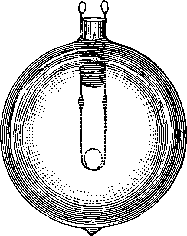
Fig. 280h.
The great advantages offered by electric glow lamps over gas-lights caused them to be speedily adopted by the most enterprising managers of theatres and places of amusement. Mr. D’Oyly Carte had the Savoy Theatre, in London, completely fitted up with these lamps in 1881. The light was soft and agreeable, it did away with the risks of fire both for the audience and the performers: for the footlights and scene-lights were also electric glow lamps, and the coolness of the house and greater purity of the air were at once appreciated. Several other London theatres have since adopted the incandescent electric lamps, and it is obvious that the system will become universal. In all ocean-going passenger steamers, electric lighting of the saloons and cabins is now the rule. No mode of illumination so readily adapts itself to the production of artistic and decorative effects as the glow lamps: for the covering glasses may be tinted of any required shade, and the lights may be placed in any position. Small glow lamps are occasionally used as personal adornments, when placed, for instance, as part of a lady’s head-dress amidst diamonds, a novel effect of great brilliancy is produced. It need hardly be said that in this application the wearer is not required to carry a dynamo about with her, for the electricity is supplied in a manner much more convenient for this purpose by a device presently to be described. For several years electric incandescent lamps, supplied by the like means, have been in 530action every night in the carriages of the trains running between London and Brighton, and more recently the Company have had electric reading lamps of five candle-power fitted up in the carriages of the main line trains. They are placed at the backs of the seats just above the passengers’ head. When anyone wishes to make use of one of these lamps, he places a penny in a slot, and then, on pressing a knob, the light appears, and at the end of half an hour it is automatically extinguished; but, of course, it can again be made to appear by another penny dropped in the slot, and so on every half-hour as long as may be required.
To maintain the electric light (whether arc or incandescent) quite steady, the greatest uniformity in the speed of the dynamo is essential; and if the prime mover by which it is worked, whether steam-engine, gas-engine, water-wheel, or turbine, is not perfectly regular in its action, the lights will fluctuate in brightness, and thus produce an effect which is very unpleasant. This is entirely obviated by the adjunct we have now to describe, which not only is most efficient as a regulator, but is, moreover, of still more importance by also providing the means of storing up the electrical energy in a portable form. The reader will have understood that in a voltaic cell the production of an electric current is the concomitant of a chemical union of substances within the cell (p. 493). Now, in the experiment shown in Fig. 263 (p. 498), it is the reverse of combination—namely, the decomposition of the water that is supposed to be effected under the influence of the current from a galvanic battery, and the poles are so connected that the direction of the current in the liquid while the decomposition is proceeding is from the wire in the O tube to that in the H tube. If the experiment be interrupted by removing the battery, and then putting a galvanometer (Fig. 258) in its place, the galvanometer will immediately indicate a current passing through the apparatus in a direction the reverse of the former one—that is, in the liquid it goes from H to O, and the volumes of the gases will slowly diminish while water is reproduced by imperceptible and gradual re-combination. Batteries can be made by joining up a series of arrangements like Fig. 263, consisting of nothing but strips of platinum surrounded by hydrogen and oxygen gases and the intervening acidified water. Analogous results are obtainable by cells containing other compounds with suitable metallic poles, for when decomposition has been effected through a series of such cells by a sufficiently powerful current from a primary battery, the series of cells will constitute, on removal of the primary battery, a secondary battery, for when the terminals of this are joined, the current will flow in the reversed direction while the separated parts of the original compounds are re-combining within the cells. These secondary batteries are called also polarisation batteries. A form of secondary battery was contrived some years ago (1859) by M. Gaston Planté, in which the current of the primary battery was made to act on plates of lead immersed in dilute sulphuric acid. The effect was to coat one of the lead plates of each pair with lead oxide; and in the action of the secondary battery this was reversed, and the plates gradually returned to their original condition, when, of course, the current ceased. Some improvements were made in the Planté battery by Faure, who coated one of a pair of very thin lead plates at once with a film of red oxide of lead, and used a layer of felt to separate it from the other plate. Such arrangements have been called “accumulators”; another term applied to them is “storage batteries”; but it is not to be supposed that in them electricity is stored or, so to speak, 531bottled up. They consist merely of such an arrangement of materials as that when a current (direct, not alternating) from a dynamo is passing, certain substances are placed in a position of chemical separation in such a manner that in re-combining an equable current of electricity is produced in the conductor externally uniting them. We need not notice some slight modifications of the Faure cells that have been lately introduced, as no new principle is involved. The light of incandescent lamps worked by the Faure accumulator is perfectly free from the fluctuations which may usually be noticed when the lamps are directly connected with the dynamo only. Even if the engine should stop altogether, the light may be maintained for hours. The accumulator has also the advantage of giving out the electric energy that may have been imparted to it days before; so that when a house is fitted up with an independent electric light installation, there is no necessity for running the dynamo all the time the lamps are in use, as two or three days weekly may suffice to charge all the accumulators. Then there is the portability of the accumulator, which permits electrical energy to be made use of in situations where dynamos and prime movers would be impossible. It is said that a large Faure cell weighing about 140 lbs. can receive and give out energy equal to one horse power for one hour. In the arrangement for the reading lamps in railway carriages referred to above, accumulators are placed under the seats; and it need hardly be said that when the electric light has been seen in a coiffure, a small Faure cell concealed about the wearer’s person has supplied the current. A very interesting and useful application of the accumulator is the portable electric light lamp for miners made by the Edison-Swan Company. It is simply an incandescent lamp protected by a strong glass cover attached to the side of a cylindrical case containing a four-celled accumulator. This lamp is provided with an ingenious contrivance by which the circuit would be interrupted, if by accident the outer glass cover of the lamp were broken. Let us now see what another new development of the applications of electricity gains by the use of accumulators by turning our attention to the electro-motor.
At the Vienna Exhibition of 1873, the Gramme Company showed two of their machines, and it is said that when one of these machines was at rest, a workman connected the ends of two covered copper wires with the other machine, thinking that these were placed to carry the current from that machine when in movement. Everybody was surprised when, without any power from the machinery, the ring was soon in rapid rotation. These wires were in fact joined up to the other Gramme machine which was already in action, and it was the current from this that set the former in motion. There is no reason why this story should not be perfectly true, although there are good reasons for believing that the electro-motor was the result of no such accidental circumstance. The attractions and repulsions between the poles of electro-magnets was soon seen to supply an available source of motive power, and the subject has been already mentioned on page 518. Professor Jacobi, of St. Petersburg, seems to have been the first who constructed an electro-magnetic engine, the exciting power being the current supplied by a voltaic battery. This was in 1834, and in a few years afterwards the Professor applied his engine to a small paddle-wheel boat, 28 feet long, which was electrically propelled for several days, but at a slow speed. The engine in this case was virtually a magneto-electric machine worked backwards, that is, instead of applying power to turn the machine and so produce a current 532of electricity, the current was supplied by the battery and produced power. In 1850, an electro-motor of five horse power was shown by an American, Mr. Page, the principle of which may be illustrated by supposing a reversal of the action represented in Fig. 271, thus: if, instead of producing currents by moving the magnet, C, in and out of the coil, A B, we substitute a battery for D, we can, by alternating the direction of the current through the coil, cause a reciprocating motion of the magnet, C, and this again may be described as a magneto-electric machine worked backward. It was soon recognized that no practical electro-motor was adequate to the production of such high powers as the steam engine supplies, and that the cost must necessarily many times exceed that of steam power. But certain advantages, nevertheless, pertained to the electro-motor in certain positions, as instance in safety, and where a small force only was occasionally required. Now, when the Gramme machine was invented to supply currents of electricity under conditions much more favourable than the magneto-electric machines it superseded, and at a cost vastly less than that of any voltaic battery, it is highly improbable that the relation of the new current generator to the production of electro-motive power would long be overlooked.
The electro-motor may, therefore, be considered simply as a dynamo worked backward, and almost any form of dynamo may in this way be used as an electro-motor, that is, a current being supplied either from a battery or from a dynamo, the motor converts the electrical energy into mechanical energy. Any dynamo that supplies a direct and continuous current can thus be used; but there are certain conditions which make it desirable to somewhat modify the proportions and arrangement of the several parts when the machine is for motor purposes.
In general, any source of current may be used, but in the applications of the electro-motor there are chiefly two methods in practice of supplying the current. The one takes the current from a dynamo in motion, the other from an accumulator which has previously been “charged” by a dynamo.
Both of these methods are used in the familiar and interesting application of the electro-motor to the propulsion of carriages on tramways and railways. For the latter, indeed, an attempt was made half-a-century ago on the Edinburgh and Glasgow railway, to employ the force of an electro-magnetic machine actuated by a battery. This was in 1842, and although this electric locomotive was fitted up completely, it did not attain a speed of more than four miles an hour. The weight with the batteries, carriage, etc., exceeded five tons. But in the recent inventions which have been in practical operation in many places, it is found quite easy to dispense with any current producer on the electric locomotive itself, for the electricity is supplied by a fixed dynamo and the current is transmitted along the line by a conductor from which a sliding contact conveys it to the electro-motor, which is attached to the framework of the carriage and acts on the driving axles of the wheels directly or by toothed gear. In such cases the return current is carried either by another conductor or by the rails themselves. In another arrangement one rail conveys the current to the locomotive and the other returns it. When the rails are so used they have, of course, to be insulated from the ground and laid with special electrical contact pieces joining their consecutive lengths, and all the carriage wheels have to be insulated, so that the currents shall flow only through the coils of the electro-motor. A railway on this system has 533been worked at Berlin for some time, and a short tramway on the same plan has lately been opened at Brighton. The Bessborough and Newry Electric Railway (Ireland) uses a single separate conductor three miles long, and the power is supplied at a very small cost from a dynamo station near the middle of the line, where water power is taken advantage of to drive a large turbine. Quite recently electric propulsion has been adopted on some of the short tunnel lines in London, and it is quite probable that ultimately the system will be adopted throughout the whole course of the underground railways, with the view of obtaining a purer and more agreeable atmosphere.
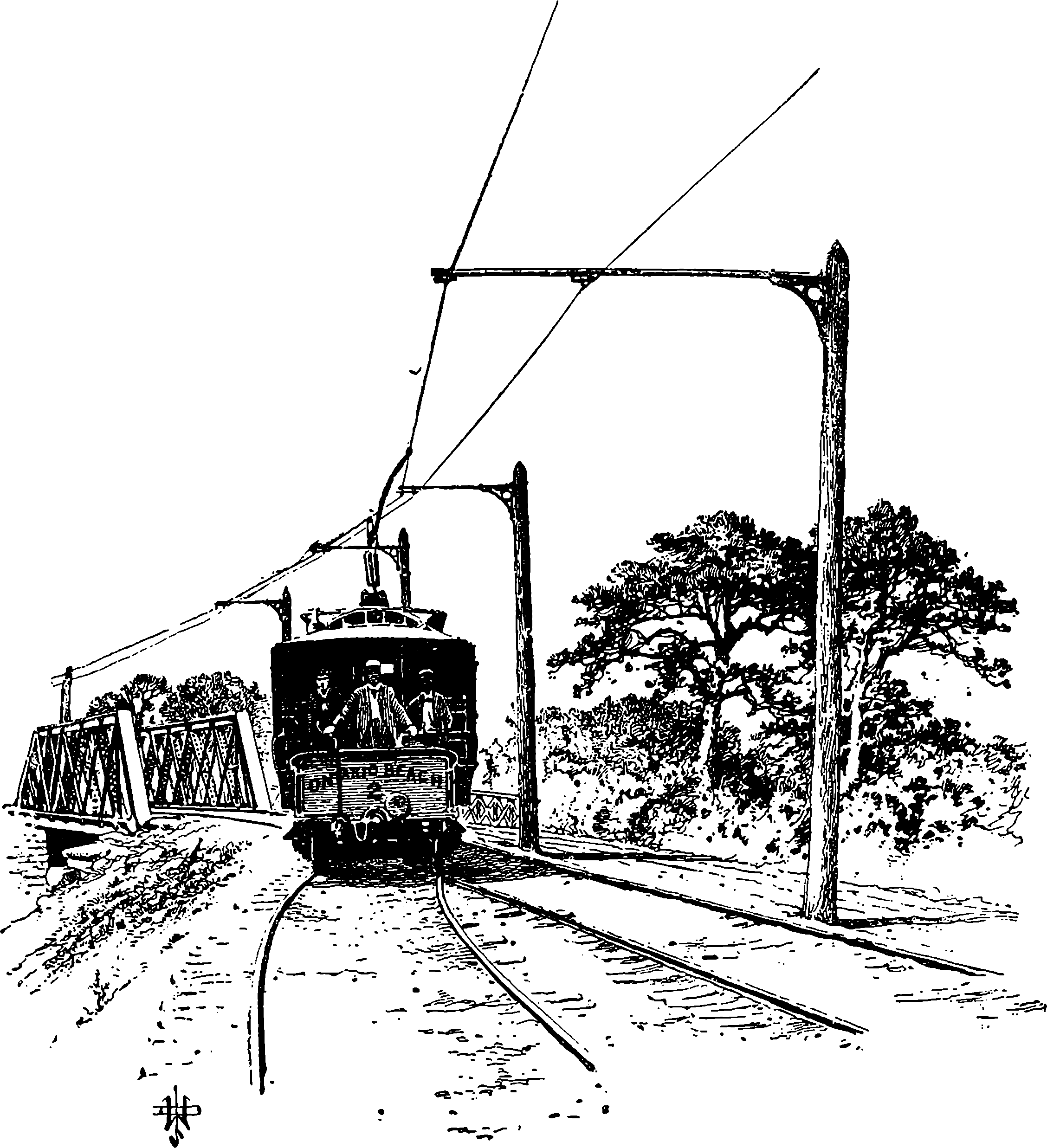
Fig. 280i.—Poles with Single Arms for Suburban, Roads.—The Ontario Beach Railway, Rochester, N. Y.
A very light electric railway has been designed, in which the cars run along rails attached to posts at such a height above the ground as may be 534required to make the line level, or with only slight gradients. The rails also serve as conductors. This is known as the telepherage system, and it is found to be well adapted for light loads in an undulating country.
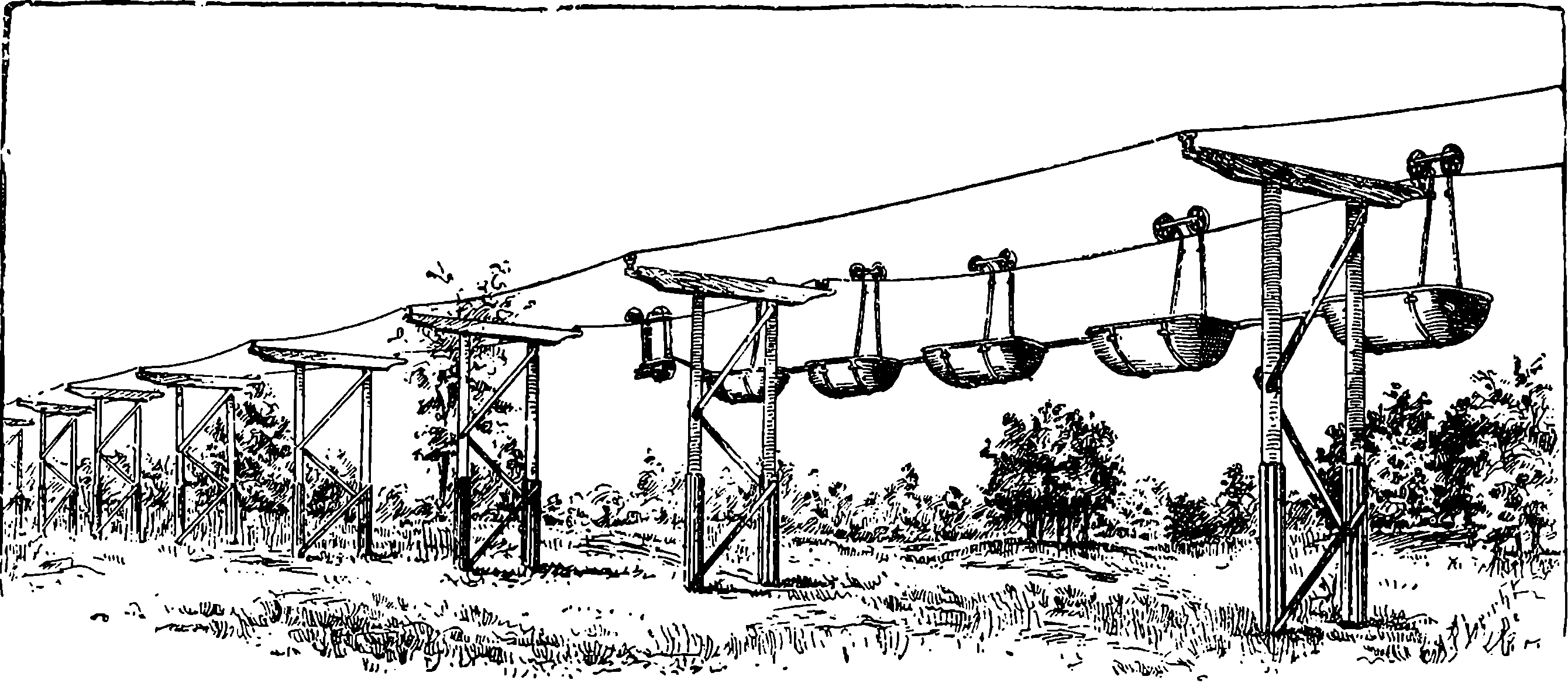
Fig. 280j.—The Glynde Telepherage Line, on the system of the late Fleeming Jenkin.
The other plan which makes use of accumulators commends itself for application to ordinary tramway carriages, because no conductors are required along the line, and each car can move independently. The chief objection is the great weight of the accumulators and the space they occupy, although they are usually placed under the seats without much inconvenience. There are at present (January, 1890) six electric tramcars running in London, and the accumulator system would no doubt have been applied largely as the motive power for the ordinary street omnibus, but for the difficulty of controlling them under the momentum of the great mass of the accumulators, etc. The same objection lies against the use of the accumulators and motors for propelling tricycles, although such machines have really been used. But accidents such as occasionally happen to such vehicles would be attended with additional risks of injury from the acids of the secondary battery, etc. But there is one mode of using electric propulsion, that is free from every objection and, indeed, offers great advantages. Only two years ago the first electric boat on the Thames was tried experimentally between Richmond and Henley, and the result was entirely in favour of the electric over the steam launch. The Faure battery, or so-called “storage cells,” are arranged beneath the floor of the boat for most of its length in the smaller boats, and the electro-motor is directly coupled with the screw shaft. The electric launch has these advantages: perfect safety, freedom from dirt and smoke, no thumping or vibrating, no noise of steam discharge, or smell of hot oil, no engineer or stoker is required, and much larger space available for passengers. One of these electric launches, not going full speed, is able to travel sixty miles without having the accumulators recharged. A considerable number of these launches are already in use, and many more are in course of construction. They are made of all sizes, from the smallest to those that will carry quite a large 535company, and may be used for excursion parties on the river. The description of one of these last states that she is 65 feet in length, and 10 feet across the beam. She can carry sixty passengers, and twenty can dine in the saloon at one time. There are lavatories, pantries, dressing rooms, etc., and a brass railed upper deck, with an awning. At night this boat is lighted up with electric glow-lamps, the current for these also being supplied by the accumulators. The Electric Launch Company has stations with Gramme machines at work to charge cells ready to replace exhausted ones at several places, namely Hampton, Staines, Maidenhead, Boulter’s Lock, Henley, Reading and Oxford. There is every prospect of a general extension of the electric propulsion of boats, and visitors to the Electrical Exhibition at Edinburgh, in 1890, will find electric launches taking holiday makers as far as Linlithgow. The boats will be like those on the Thames, fitted with the Immisch motor. Some electricians are now sanguine enough to believe that even for large vessels electricity will yet be able to compete with steam in special cases.
The modes of using electric propulsion that we have just noticed furnish a very interesting chain of conversions of one form of force into another, with a reversal of the order of transformation at a certain point. Let us begin with the carbonic acid gas that existed in the atmosphere of the carboniferous geological period. The solar emanations were absorbed, and used by the leaves of the plants to separate the two elements of the gas,—the plant retaining the one in its substance and returning the other to the air. The plant becomes coal; and ages afterwards the particles of the two separated elements are ready to re-unite and give out in the form of heat all the energy that was absorbed by their separation. This heat is in the steam-engine converted into the energy of mechanical power. This mechanical power is in the dynamo expended in moving copper wires through a magnetic field. Every schoolboy who has played with a common steel magnet—and what boy has not?—knows that the space immediately round the magnet is the seat of strange attractive and repulsive force, for he has felt their pulls and pushes on pieces of iron or steel. This mysterious space is the magnetic field, and although a person would not be able to perceive that mechanical force is expended when he moves a single copper ring across such a field, he will readily become conscious of the fact when he moves a number at once that form a closed circuit; and he should not omit the opportunity of feeling this for himself if he is allowed to turn the handle of such a machine as that represented in Figs. 275 or 277. The mechanical power is absorbed in the dynamo because the movement induces an electric current that would of itself produce motion in the machine in the opposite direction. However, the electricity induced by magnetism and motion is made to pass through the Faure cell or accumulator, when it does chemical work by separating oxide of lead from sulphuric acid, leaving these substances in a position to unite together again, when this action produces a reverse current of electricity through an external metal circuit. The coils of the electro-motor form this circuit; the electricity induces magnetism, and the magnetism gives rise to visible motion and mechanical power.
From what has been already said, it will be obvious that a pair of covered copper wires connecting a dynamo with an electro-motor becomes a very convenient means of carrying power from one place to another. There are situations in which shafts, belts, or any other mechanical expedients are troublesome or impossible to use for this 536purpose. For instance, a dynamo working at the mouth of a tunnel or coal-pit may be made to drive any machinery within with nothing between but the motionless wires. Or a single dynamo will supply moderate power to a number of small workshops, provided each has an electro-motor, with no other connection than a pair of copper wires. This arrangement is found very advantageous for light work and where power is required occasionally, as in watch-making, the manufacture of philosophical instruments, etc. Such moderate power is occasionally in demand also in private houses, to drive sewing machines, lathes, etc.; and it is obtainable from the same source as the current for lighting. Private installations for lighting purposes usually have a dynamo driven by a gas engine, and working into a set of accumulators. It seems not a little remarkable that if the gas were burnt in the ordinary way instead of being used in the gas engine, it would give only a fraction of the amount of the light it causes to be given out by the electric light lamps. But at the present time, houses and business premises are supplied with electricity by companies who carry electric mains through the streets. In England these electric mains, which are thick insulated copper wires, are inclosed in iron pipes and laid beneath the pavement, like the gas mains. In the United States, where electric illumination is much used, the conductors have been usually carried overhead like telegraph wires, but not a few fatal accidents have occurred from these conductors falling into the streets. There is no reason to doubt but that in a short time it will be as common for households to draw upon such electric mains for their supply of light and power as it now is to draw gas and water from common mains. The electric supply companies have central stations in suitable positions, where very large and powerful dynamos are regularly driven by steam power. These stations are provided with appliances for measuring the currents and for duly controlling the energy sent out. What will appear very extraordinary when we remember that electricity is in itself unknown, is that the quantity supplied to each house or establishment can be actually measured, and is paid for by meter as in the case of gas. As already said (page 498) electricity can only be measured by its effects, and it is the chemical effect which it is found convenient to use for the purpose we are speaking of. The plan is simply this: two plates of zinc dip into a solution of sulphate of zinc, and from the one to the other there is sent through the solution one-thousandth part of the current to be measured. While the current passes, zinc is deposited on the plate towards which the current goes in the solution, and if this plate is periodically weighed this furnishes the measure of the total current. But how is just one-thousandth of the whole current taken off from the rest and made to circulate through the measuring apparatus? This is very easily done by taking advantage of the law of derived circuits, which for our present purpose may be stated thus: when a current of electricity finds two different circuits along which it can pass, it will divide and circulate through both of them, but the greater part will pass through the circuit of less resistance (if there be any inequality), and by adjusting the resistances of the circuits we can divide the current between the two partial or derived circuits in any required proportions. Electric resistances, it may be mentioned, depend upon the length, section, and nature of the conductor, and are very easily measured and adjusted.
While the method just explained serves very well to measure the quantity of electricity that has passed through a conductor in a given period, 537provided that the current has always been in the same direction, it will be sufficiently obvious that it would fail altogether in the case of alternating currents. And, in fact, even in the case supposed this mode of measurement does not take account of the real energy set in motion. A reference to page 498, where the differences of electric currents are mentioned that are commonly spoken of—tension and quantity—will show that electric effects depend upon more than the quantity of electricity passing. Forms of apparatus have been devised for recording the total energy supplied; but their construction and principles are too complex to be here explained. In some cases high tension currents are required, in others it is quantity and not tension that is sought for; and there are ways of transforming the qualities of currents so that the same source shall supply electricity of either class. An example of this may have been noticed in the action of the Ruhmkorff coil, where the mere interruption of the primary or battery circuit, which possesses so little tension that of itself it could not give rise to a spark, nevertheless produces a wave of electricity in the secondary circuit of a tension so high that sparks several feet long may be produced by it.
A somewhat recent application of the electric current of the dynamo may be just mentioned here. It is what is known as electrical welding, and depends upon the heat developed by currents being proportioned to the electrical resistance for each part of the circuit. The heat thus generated, where the current passes between two surfaces of metal, even of considerable dimensions, is sufficient to bring them to a semi-fluid condition, so that when simply pressed together they coalesce into one mass. In this way pieces of iron work can be welded together in situations where it would be either inconvenient or impossible to heat them by furnaces.
The reader who has followed the last article will probably be prepared to admit that “the magnetic field” is one of the most wonderful things in the whole realm of inorganic nature, as all the powerful effects we have been describing are the results of merely moving wires through it. A wire conveying an electrical current so modifies the space surrounding it, or so acts upon the unknown pervading medium, that conductors moved in it, have other currents generated in them. An intermittent current, like that in the primary circuit of the induction coil, is equivalent to a movement of the magnetic field in regard to the secondary coil, so that the general principle in the coil and the dynamo is fundamentally the same. Quite recently, Professor Elihu Thomson has shown some very novel mechanical effects of repulsions and rotations of conductors placed near the poles of a coil through which rapidly alternating currents are passing. [1890.]
We already hear of natural forces which have hitherto in a manner run to waste being now utilised in man’s service by the advantage taken of the capability of a slender wire to convey power. A notable instance is in the case of the famous Falls of Niagara. Here the head of water is used to drive turbines; our readers must not run away with any notion of huge water-wheels being placed below the falls. But from the high level of the water above the falls a tunnel has been cut which brings the water into pipes 7½ feet in diameter, and these deliver it into three turbines, in passing through which it develops a force of 5,000 horse power, and this force is communicated to a steel shaft 2½ feet in diameter, connected with the revolving parts of the dynamo. Mr. G. Forbes, the engineer, states that the company who have undertaken this enterprise are supplying, 538with a handsome profit to themselves, electrical current or power at ⅛th of a penny per unit, for which English companies charge sixpence. That is, Niagara supplies power at 1 48th of the price it can be obtained from coal.
The fact that mechanical power can be brought from a distance to everyone’s door by a slender wire, and at small cost, suggests the possibility of great social and industrial changes being effected in the future by that one condition. Think of the abolition of factory chimneys and smoke, nay, even of the abolition of the factory system itself, for cheap power transmission seems to promise much in that direction, and there is a shadowing forth of still more in
THE NEW ELECTRICITY.
The Leyden jar and a few of its most obvious and common effects have been touched upon already, (page 490); but the phenomena which are revealed by a careful study of its charge and discharge show that these are by no means of the simple kind that has generally been supposed. Thus, for instance, if the magnetising effects of what is called current electricity be borne in mind, especially the definiteness of this action as regards the direction of the current (cf. Fig. 257), it would follow that if instead of the iron bar in Fig. 265 we place within the coil some unmagnetised steel needles we should find after passing a current or discharge that these have become converted into permanent magnets, and that their north poles are always towards the left of the supposed current. Years ago experiments were made to ascertain whether the discharges of a Leyden jar repeatedly passed through a coil would magnetise needles in the same way, because it had been assumed that the discharge is simply a current of extremely short duration and of quite definite direction. As far back as 1824 it had, however, been observed that the needles were magnetised sometimes in the wrong direction, yet no attempt was made to explain this—it was sometimes merely mentioned in the books as “anomalous magnetisation.” Dr. Henry of Washington, U.S.A., experimented on the subject, and in 1842 referred this action to a condition of the discharge which had never before been suggested. He says “we must admit the existence of a principal discharge in one direction, and then several reflex actions backward and forward, each more feeble than the preceding, until the equilibrium is obtained.” Some five years afterwards Helmholtz had independently arrived at the same conclusion, and from the fact that when a succession of Leyden jar discharges are sent through the voltameter (Fig. 263) the water is indeed decomposed, but both oxygen and hydrogen are evolved at each electrode. Sir William Thomson (now Lord Kelvin) examined the question from a theoretical point of view, and in a masterly mathematical paper published by him in 1853 not only showed that the discharge must be of an oscillating character, but gave the form of equation by which the rate of oscillation is determined.
Faraday proved, as has already been stated, that the matter of the dielectric takes part in such condensing actions as that of the Leyden jar. 539The electrical charge enters into the glass, the particles of which are thrown into a certain state of strain or tension (which Faraday called polarisation), and the discharge of the jar is their release from that tension. So that it appears that whatever electricity may be, it can in some way become bound up with the particles of ordinary matter like glass and other dielectrics, and exert force upon them, which force acts always in two opposite directions. It is the opposition of the form or direction in which the electrical effect is manifested that gave rise to the conception of the two “fluids”—the “positive” and the “negative.” If these “fluids” really existed it would surely have been possible to give to an insulated body an absolute charge of either of them. But this can never be done; if, for instance, you have in the middle of a room a metallic sphere charged with positive electricity, the necessary condition is that on the walls of the apartment or on surrounding objects there is an exactly equivalent quantity or negative electricity.
The number of oscillations or alternate momentary currents in a single discharge of a Leyden jar is enormous. Theory shows that under ordinary circumstances they must be enumerated by hundreds of thousands, if not by millions; that is, the apparently instantaneous spark is really made up of say a million surgings to and fro of the electric influence. But theory also shows that the frequency of these oscillations can be controlled or adjusted through an indefinite range. A general notion of the requisite conditions may be obtained by the analogy of sound, and for this we may take the familiar case of the strings of a musical instrument, say the violin, or the harp. Everybody knows that when a stretched string or wire is pulled a little aside it is in a state of lateral strain, striving by its elastic force to return to its position of rest, and if it is suddenly let go it not only rapidly regains that position, but by the inertia of its motion is carried beyond it against its elastic force, which, however, again brings it back, and the movement is continued nearly up to the point at which it was originally released, this swinging movement persisting for an indefinite period, during which the vibrations, which have an ascertainable and perfectly regular frequency, are communicated to the sounding-board of the instrument and from that to the air, by which they are conveyed to the ear and affect the auditor as a musical note, which note is higher as the number of vibrations per second is greater. Everybody will have observed that in the violin the note yielded by each open string is higher as the tension becomes greater by turning the peg to tighten it; that the same string will, without any change in its tension, yield higher notes as shorter lengths of it are employed. Another circumstance upon which the pitch of the note depends may also be illustrated in the violin, in which it will be noted that the G string, which gives the lowest notes, is loaded with wire wound spirally round it. Here, then, are three circumstances that collectively determine the pitch or number of vibrations of a string—tension, length, weight; and if you give the measures of these to a mathematician he can tell you the note the string will emit, for the number of vibrations is given (when the measures are expressed in the proper units) by the formula
√t
n =
2l√w
This shows that we have only to adjust suitably the tension, length, and weight of a string in order to make it vibrate at any rate we please. Now in the oscillation of currents in the Leyden jar discharge there are conditions 540which correspond, by analogy at least, with those that determine the vibrations of a stretched string. These conditions are of course electrical, and they are definable in terms of electric units, which need not be discussed here. As we are leading the reader to the modern view of electricity, which sets aside the fluid theories and regards electricity as having no separate existence, but as being merely the manifestation of some condition of a universally pervading medium, the same, in fact, as the luminiferous ether, it is curious to remark that these electrical oscillations would seem to attribute to the incompressible and imponderable ether something very much like the characteristic property of matter we call inertia, by virtue of which the released cord flies past its position of equilibrium to the other side. Or may this quality be dependent on the matter of the dielectric in which the ether is, as it were, entangled?
The oscillatory character of the Leyden jar discharge was elegantly demonstrated before a large audience in a lecture given by Professor O. Lodge at the Royal Institution a few years ago. Clearly it is impossible to render perceptible to the senses the millions of periodic discharges that take place in the marvellously short space of time taken up by a spark, but by doing what is analogous to slackening the tension of the stretched string or increasing its length, that is by increasing the static capacity, which means using a large number of jars combined into a battery, and at the same time causing the discharge to pass through coils (the effect of these is to increase the self-induction of the circuit—called also impedance), an arrangement corresponding with loading the string, Dr. Lodge was able to bring down the rate of oscillation to 5,000 per second, when, instead of the crack of the ordinary discharge, a very shrill continuous sound was heard. The addition of another coil gave another load, and when the rate was thus reduced to about 500, the note emitted was that of the C above the middle A of the piano. With the rate of oscillation thus reduced, it became easy to render the discontinuity of the discharge visible by means of revolving mirrors, as in the well-known acoustical demonstrations.
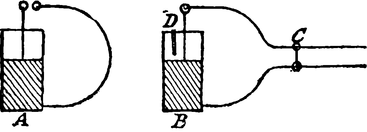
Fig. 280k.
Professor Lodge has devised an experiment which again shows the analogy of electrical oscillations with those by which sound is produced. It is well known that a vibrating tuning-fork will set another fork of the same pitch to vibrate also by mere approximation. A and B (Fig. 280k) are two exactly similar Leyden jars, the inner and outer coatings of each being connected by a wire enclosing a considerable area in its circuit, which in the case of A contains an air gap across which sparks pass when the coatings are connected with the poles of an electrical machine. The circuit of B is provided with an adjustable sliding piece C, and the coatings are almost connected with each other by a strip of tinfoil hanging over the rim but not quite reaching to the outer coating. When the jars are placed so that their wire circuits are parallel, and sparks are passing 541across the air interval of A’s circuit, a position of the slider on the other can be found when sparks also pass between the tin-foil and the outer coating. But if the slider be moved from this position, the two circuits will no longer be in unison, and the sparks in B will cease. This response of the oscillations in one jar to those set up in another of the same vibratory period is called electrical resonance.
Dr. Hertz, a professor in the University of Bonn, has opened out new paths to investigators by a brilliant series of researches which have shown that in the dielectric surrounding an electrical system executing very rapid oscillations there are waves of electro-motive and magnetic force. These researches are not capable of any condensed description here, and the reasoning is of a kind that appears mainly to the expert physicist. One of his modes of investigation required oscillations of extreme rapidity, and he obtained them by attaching to each pole of an induction coil a metal plate, and between these plates, which were in the same vertical plane, passed a stout wire interrupted by an air gap in its centre provided with small brass balls. The rate of oscillation of this arrangement was calculated as the hundred-millionth part of 1·4 second. In conjunction with this system Hertz made use of a very simple apparatus he called a resonator, which consisted merely of a piece of copper wire bent into a circle of about 28 inches diameter. The ends of the wire did not, however, meet, but were fitted with two balls, or with a ball and a point, and an arrangement by which the air gap between them could be very finely adjusted and measured. This resonator was, of course, prepared as to be in electrical tune with the original vibrator, and with it Hertz was able to examine the condition of the surrounding space. When held in the hand near the vibrator he found that sparks crossed the air space in the resonator, and that the length of the air space across which the sparks would pass varied with the position of the resonator. When the plane of the resonator was parallel with the metal planes of the vibrator and its axis in the horizontal line drawn perpendicularly through the vibrator’s air space, the sparks passed readily when the air space of the resonator was at the same time vertically above or below its centre, but they ceased entirely when it was level with the centre. He obtained these sparks when the resonator was held—in free space, be it understood—in the above-mentioned position even at a distance from the vibrator of 13 yds., the length of the apartment. By examining the results with other positions of his resonator and by other and varied experiments, Hertz was able to prove the existence of definite waves of electro-magnetic and electro-motive forces, to measure their lengths, and to show that they are capable of reflection, refraction, and even polarization by the same laws that hold with the extremely short but enormously rapid vibrations constituting light. It may here be mentioned that the existence of currents in the resonator can be shown by a Geissler tube being made to take the place of the air space, which tube is thus lighted up without any metallic or visible connection with any electrical apparatus whatever, the only requisite conditions being that its circuit be tuned to the vibrator, and in a certain position in relation to the axis of the spark space of the latter. Hertz has also shown that electro-magnetic disturbances (transversal waves) are propagated in space with a determinate velocity akin to that of light, and in short the outcome of his investigations, as well as of those undertaken by others, has been a vindication of Clerk Maxwell’s splendid theory by which light is regarded as an electro-magnetic action. Professor Righi of Bologna, 542having succeeded in obtaining shorter electrical waves than anyone before—namely, 4 10ths of an inch instead of about 20 inches—was able with them to repeat all the phenomena of optics such as reflection, refraction, circular polarization, interference, &c. It appears then almost certain that light and electro-magnetic waves or radiations are but one and the same affection of a pervading medium we call the ether.
By following up in certain directions lines of research suggested by the investigations of Maxwell, Lodge, Hertz and others, and by an unreserved acceptance of the ether theory of light, electricity and magnetism, some wonderful practical results have recently been obtained by M. Nikola Tesla, an electrical engineer now resident in New York. The experiments shown by Tesla in his public lectures have excited great interest in scientific circles, and have by many persons been witnessed with something like astonishment.
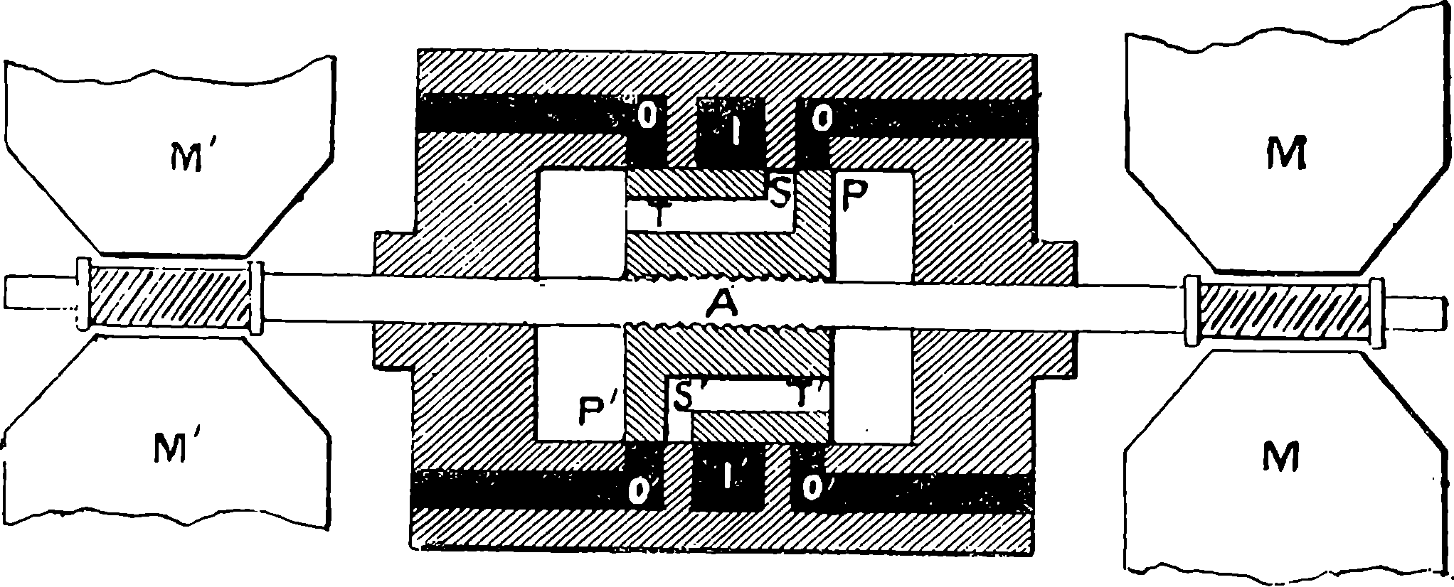
Fig. 280l.—The Tesla Oscillator.
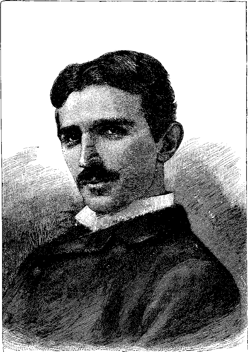
Fig. 280m.—M. Nikola Tesla.
One of the first objects of M. Tesla was to obtain alternating currents of high tension and great frequency. It may be seen from Fig. 272 that the movement of coils of wire in a magnetic field generates currents, and it has been stated that these currents are in alternately opposite directions as the coils approach or recede from the magnetic poles. In the machine represented in Fig. 280a, each revolution would produce 16 reversals of current. Tesla constructed a rotatory machine which gave 20,000 alternations of current in one second, because it had 400 poles and could be rotated at a very high speed. But of course the number of poles and the speed of the machine could not be increased beyond certain practical limits. By a happy application of the known principle of harmonic oscillations, in which all the rotatory movements of fly-wheels, coils and poles could be dispensed with, Tesla simplified the alternate current generator, reducing the moving parts to the minimum at the same time that he obtained a greater number of alternations and almost perfect regularity in their periodicity. The way in which this has been accomplished may be gathered from a careful inspection of Fig. 280l compared with the following explanation. This illustration, it should be understood, is merely a diagram in which details of mechanism are altogether omitted, and only so much shown as will serve to explain the principle. We shall take the mechanical part first, and direct the reader’s attention to the means by which an iron rod is made to perform very rapid to-and-fro movements in the direction of its length, and to do that 544with perfectly isochronous periods, which may be made longer or shorter at will, and which are quite independent of very considerable variations in the motive power. The diagram represents the apparatus in section, and the central part of it marked by letters P and P´ is a piston through which passes what may be called a piston-rod A, which projects some distance out of the cylinder at both ends. The piston is shown in the diagram in its central position, where the impelling power has no action to move it as will presently be seen. This moving power we may assume to be the compressed air applied through the ports I I´. Just to the right of the upper one of these on the diagram will be observed in the piston a slot S opening into a hollow T, which communicates directly with the space on the left of the piston. The same arrangement, with directions reversed, is seen on the other side of the piston. If now the piston were pushed a little to the left of the position shown in the diagram, the compressed air rushing from I through the slot into the opening S T would impel the piston towards the right, and it would be carried onward by its inertia beyond the position shown in the figure towards the right, but in doing this the access of the compressed air on the left would be cut off, and the slot communicating with the space on the right hand would allow the compressed air to act in the space P, checking the further advance of the piston to the right, acting like a spring or elastic cushion, and again driving the piston to the left, during which movement the air that has done its work is allowed to escape at the outlet O O. The same cycle of operations will be rapidly repeated, but the rate of oscillation admits of control, for the larger the air chamber in which the air is compressed by the momentum of the piston and rod, the less will it be compressed and the less powerfully it will resist, while with a smaller capacity of air-chamber the more powerful will be the back spring of the imprisoned air. On the other hand, the mass that is moved may be increased; that is the weight of the rod, &c., may be increased. In any case the oscillations will be perfectly regular, because the force which tends to bring the piston to its position of equilibrium will be always proportionate to its distance from that point. So that we have here a rod shooting in and out shuttle-wise with the utmost regularity and with almost any desired rapidity, controllable under precisely the like conditions as the stretched string already mentioned, for as the tension of the string is the measure of the force with which it strives to regain its position of equilibrium, so the compression of air in the chamber behind the piston; and as the loaded string vibrates slower, so will the loaded piston. So much for the mechanical part of this machine, for we may omit all details of valves, &c. The electrical arrangement is very simple and of the greatest efficiency. On each projecting end of the piston are wound coils of insulated copper wire, which being shot in and out across a powerful magnetic field between the jaws of very large electro-magnets M M´ cut the “lines of force” to the best advantage, and from these coils alternating currents of high tension and frequency are gathered up. The vibrating rod is steadied by working in bearings (not shown). The electro-magnets are actuated as usual by coils of insulated wire surrounding their iron cores. In the motion of the moving coils there are electrical forces called into play which in mechanical effect control the movement in the same way as the air-springs, and as these electrical forces admit of certain adjustments and have calculable effects, the mechanical period of the machine and the electrical one can be made to accord, and thus to, as it were, 545sustain each other, and assure a perfectly isochronous periodicity, even with considerable variations of the impelling force. Though we have supposed compressed air as the actuating agent, steam has been applied in some slightly modified forms of the machine, and sometimes at the high pressure of 350 lbs. per square inch. Such is Tesla’s alternating current producer, or the Tesla Oscillator, as it has been called. This, of course, is a very different thing from the vibrator of disruptive discharge already mentioned in connection with the experiments of Professor Hertz. Tesla also uses the disruptive discharge, and what with the high frequency and the great tension of his currents, he obtains electric oscillations of hitherto unequalled rapidity, calculable at thousands of millions per second. He claims, indeed, to be able to agitate the ether at rates of undulation comparable with those of light itself (500 billions per second). Some of the experiments he has shown certainly lend support to such an explanation. The lighting of electric lamps with but one metallic connection, and that held in a person’s hand, and causing Geissler tubes to light up without any metallic connections whatever, and making gas at ordinary pressures luminous, a lump of charcoal contained in a closed glass vessel to become red-hot while the vessel is merely held in the hand, are certainly phenomena that cannot be explained on the old lines. The space between two large surfaces of metal 15 feet apart, and forming the poles of an oscillatory system, is shown to be full of light-forming influences, as when phosphorescent substances contained in closed glass vessels glow intensely, the glass being apparently no obstacle. According to Tesla, you make space and matter equally permeable to ethereal undulations when these are tuned, so to speak, to the proper frequency.
Many of the strange effects Tesla has shown are referable to the principle of electric resonance; such are the powers of a coil with no metallic connections with any other apparatus and removed, by a distance of many feet, from any current-conveying wires. Tesla’s workshop was an apartment 40 feet long and 20 wide, and the wires connecting the poles of his oscillator were carried round the walls, while in the centre of the workshop stood a very large but entirely insulated coil, between the terminals of which an ordinary incandescent lamp was placed. This lamp was brilliantly illuminated when the oscillator was in action. The electric qualities of this coil were so adjusted that its currents came into tune with the ethereal vibrations propagated from the conductor round the room. But further, a single hoop of copper wire of the proper diameter and thickness could be brought into unison with the coil, and when held in the hand over the latter, even at a considerable distance, incandescent lamps attached to it were lighted up by the induced currents. Many other novel experiments have been shown by M. Tesla, but they need not here be described, as they have yet to be connected with the logical study of the entire class of phenomena. M. Tesla speaks somewhat sanguinely of being ultimately able to convey signals, and even power, to a distance, not merely with one wire but with no wires at all! Another thing he looks forward to is to set the electricity, or rather the ether that interpenetrates the matter of the whole earth, into a state of agitation. This seems what is commercially termed “a large order;” but we have seen that every Leyden jar, every coil, and in fact every electrical system, has its own period, and if by any possibility we could discover, or by chance hit upon the earth’s electric vibration period, it is not antecedently impossible that even the comparatively 546small efforts of such oscillatory vibrations as we could produce, would by their accumulation agitate the earth’s ether. It is well known that very small impulses, so tuned as to correspond with the natural period of a considerable mass, will produce striking mechanical effects. Thus, a troop of soldiers passing over a bridge have often been known to break down a structure that would have supported their mere weight many times over, because they were all marching together and with a step corresponding in time with the oscillatory period of the bridge. It is now always enjoined in the military orders that troops in crossing a bridge must “break step.” Another familiar illustration of the accumulation of small synchronous impulses is the experiment of singing into a glass goblet the note corresponding with its vibration period. The singer merely by sustaining this note for a short time often succeeds in shivering the glass into fragments. M. Tesla believes that he has already succeeded in agitating the earth’s ether to some extent; he does at least obtain flaming purple streamers passing into the air from one end of a coil, while the other is connected with the earth.
These discoveries and theories appear likely to lead to many unforeseen results, valuable for both science and its applications, and such as may far surpass the expectations of those who take less enthusiastic views of the matter than M. Tesla and his friends do. The theoretical properties of the ether and the conditions of it, which are held capable of making it the scene and the medium of all the hitherto so-called ponderable and imponderable forces, have not been completely worked out. The experiments that have been already made show that disturbances of very different kinds may be propagated in the ether by undulations of any length from less than 1 60000th part of an inch, as in the case of violet light already spoken of, to the 1,200 miles attributed to certain electrical conditions.
The foregoing sentences, describing the discoveries of Hertz and others, had not long been penned before it had become possible to announce that they had borne fruit in as extraordinary an invention as could have distinguished the close of an extraordinary century. It is the realization of what the most accomplished electrician would not long before have pronounced a dream—namely, wireless telegraphy. The general principle of it should not be obscure after the account of the “Hertzian waves”; but our space does not permit a description of details of its working out in a practical form by a young Italian electrician, Signor Marconi. We have already seen that a Geissler tube, when its circuit is properly attuned, can be lighted up by the magneto-electric disturbance propagated without material contacts, and this itself would constitute a method of signalling to a distance. On the same principle, a discharge may be determined by the “wave” between conductors in certain adjustable conditions of electric tension, and in this way local circuits may be brought into play, and ordinary telegraphic effects produced, as described in the following article. The actual apparatus to receive the ethereal impulses is extremely simple—merely a little fine metallic dust (nickel and silver) in a glass tube included in the resonator circuit by a wire at each end, touching the dust. This gathers together, or coheres (hence the apparatus is called the coherer), under the magneto-electric influence, a local battery discharge then passes, completing a circuit, and the dust has to be shaken loose again by a mechanical agitation. Marconi has been able to signal over a distance of forty-three miles.
547
Fig. 281.—Portrait of Professor Morse.