FIRE-ARMS.
Reading edition
The invention of gunpowder—or rather its use in war—appears at first sight a device little calculated to promote the general progress of mankind. But it has been pointed out by some historians that the introduction of gunpowder into Europe brought about the downfall of the feudal system with its attendant evils. In those days every man was practically a soldier: the bow or the sword he inherited from his father made him ready for the fray. But when cannons, muskets, and mines began to be used, the art of war became more difficult. The simple possession of arms did not render men soldiers, but a long special training was required. The greater cost of the new arms also contributed to change the arrangements of society. Standing armies were established, and war became the calling of only a small part of the inhabitants of a country, while the majority were left free to devote themselves to civil employments. Then the useful arts of life received more attention, inventions were multiplied, commerce began to be considered as honourable an avocation as war, letters were cultivated, and other foundations laid for modern science. If such have really been the indirect results of the invention of gunpowder, we shall hardly share the regret of the fine gentleman in “Henry IV.”:
“That it was great pity, so it was,
That villanous saltpetre should be digged
Out of the bowels of the harmless earth,
Which many a good tall fellow had destroyed
So cowardly.”
We often hear people regretting that so much attention and ingenuity as are shown by the weapons of the present day should have been expended 170upon implements of destruction. It would not perhaps be difficult to show that if we must have wars, the more effective the implements of destruction, the shorter and more decisive will be the struggles, and the less the total loss of life, though occurring in a shorter time. Then, again, the exasperated and savage feelings evoked by the hand-to-hand fighting under the old system have less opportunity for their exercise in modern warfare, which more resembles a game of skill. But the wise and the good have in all ages looked forward to a time when sword and spear shall be everywhere finally superseded by the ploughshare and the reaping-hook, and the whole human race shall dwell together in amity. Until that happy time arrives—
“Till the war-drum throbs no longer, and the battle flags are furl’d
In the Parliament of man, the Federation of the world—
When the common sense of most shall hold a fretful realm in awe,
And the kindly earth shall slumber, lapt in universal law,”—
we may consider that the more costly and ingenious and complicated the implements of war become, the more certain will be the extension and the permanence of civilization. The great cost of such appliances as those we are about to describe, the ingenuity needed for their contrivance, the elaborate machinery required for their production, and the skill implied in their use, are such that these weapons can never be the arms of other than wealthy and intelligent nations. We know that in ancient times opulent and civilized communities could hardly defend themselves against poor and barbarous races. But the world cannot again witness such a spectacle as Rome presented when the savage hordes of Alaric swarmed through her gates, and the mighty civilization of centuries fell under the assaults of the northern barbarians. In our day it is the poor and barbarous tribes who are everywhere at the mercy of the wealthy and cultivated nations. The present age has been so remarkably fertile in warlike inventions, that it may truthfully be said that the progress made in fire-arms and war-ships within the second half of the nineteenth century surpasses everything that had been previously accomplished from the time gunpowder came into use. Englishmen have good reason to be proud of the position taken by their country, and may feel assured that her armaments will enable her to hold her own among the most advanced nations of the world.
The subject of fire-arms embraces a very wide ground, as will appear if we consider the many different forms in which these weapons are constructed in order best to serve particular purposes. Pertaining to this subject, attention must also be directed to the modern projectiles and to the newer explosives that have largely taken the place of ordinary gunpowder. The shot gun, fowling-piece, and sporting rifle properly come under the head of fire-arms, and in the march of improvement these forms have most commonly been in advance of military muskets and rifles, the ingenuity bestowed on all their details being worthy of admiration. Nevertheless it is to the implements of war that general interest attaches; for on them depends so much the fate of battles and the destiny of nations, that whenever any country is engaged in war the question of arms becomes one of surpassing importance, enlisting the patriotic instincts of every citizen. Hence in the following pages our space will be devoted mainly to weapons of war, and more particularly to those that have been adopted by our own country.
Everyone of course is aware that guns, cannon, and gunpowder are by no means inventions of the nineteenth century; but there are fewer 171acquainted with the fact that rifling, breech-loading, machine guns, and revolvers were all invented and tried hundreds of years before. The devices by which some of these ideas were sought to be realised in past ages appear to us in some instances very primitive, not to say childish, when compared with modern work: but it must be remembered that nearly all the appliances required for producing such weapons had themselves to wait for their invention until the nineteenth century; such, for instance, as the steam-hammer, powerful and accurate tools, refined measuring implements, material entirely reliable such as the new steel, and also scientific investigations of all the conditions involved. The military fire-arms are of so many different forms and patterns that we can deal here with but a selection from the various services. If a rough classification had to be made, the most obvious distinction would be between the weapons the soldier carries in his hands (small-arms) and those which are mounted on some kind of carriage and discharge projectiles of much greater weight (ordnance). Ordnance again includes guns mounted on forts, carried in ships, or taken with an army into the field, in each case coming into action under different conditions. Partaking somewhat of the nature of both field-guns and of small-arms are the machine guns, of which the French mitrailleur was the first example, afterwards developing into much more effective weapons in the hands of Gatling, Gardner, Nordenfelt, Maxim, and Hotchkiss.
As much will have to be said about rifling the bores of muskets and cannon, we may here explain the nature and object of this device. The projectiles used in all guns down to comparatively recent times were almost invariably of spherical form, and could indeed scarcely be otherwise with smooth-bore weapons. As the diameter of the shot would necessarily be something less than that of the bore of the barrel, a considerable loss of power would result from the escape of the powder gases between the shot and the barrel, which escape is known as windage. Another disadvantage of the spherical projectile is that for the same weight of metal the air offers a greater resistance to its passage, and consequently checks its speed more quickly than that of any other circular form; for the air resistance is proportional to the square of the diameter, and therefore if we take a ball of 1 in. diameter and a cylinder of 1 in. in length, each having the same weight of metal, the diameter of the cylindrical shot will be a little more than four-fifths of an inch, and the air resistance to the ball will be exactly half as much again as to the cylinder, that is, in the proportion of 3 to 2. Again, the passage of the spherical shot within the barrel of the gun will not be in a straight line, but in a series of rebounds from side to side, and its direction on leaving the muzzle will depend upon which part of the bore it just before impinges on, as from that it will also take a rotatory “twist” that will in part determine its path through the air.
Now if an elongated projectile were fired from a smooth-bore gun, its course through the air would be erratic to a degree impossible to the spherical shot, for it would turn end over end with deviations that would make aiming impracticable. But if the elongated projectile is made to spin rapidly enough about its longitudinal axis, it flies through the air quite steadily, the axis of rotation remaining parallel to that of the gun throughout the whole flight. The steadiness due to rapid rotation has familiar examples in spinning tops, in gyroscopic tops, in the way arrows are feathered so that the air may cause them to revolve axially, and so 172on. The axial rotation of the projectile is effected by ploughing out in the cylindrical barrel of the gun a number of spiral or twisting grooves, which the projectile is compelled to follow as it travels along the barrel, either by means of corresponding protuberances formed upon its surface in the first instance, as in Jacob’s bullets, or by studs let into it, as in the studded shots and shells for ordnance which constituted at one time the regulation plan adopted by the British Government; or otherwise by making the force of the explosion expand some portion of the projectile in such a manner that this portion shall completely fill up the grooves, thus preventing windage, and causing the projectile to follow the twist of the grooves. This is the more general method, especially since the adoption of breech-loading. The Lancaster rifling, and that advocated by Whitworth, are the same in principle, but differ in appearance, from the section of the barrel being made in the one case oval, in the other hexagonal or polygonal, but with the twist necessary to produce rotation.
Incident to the discharge of all fire-arms, great and small, is a phenomenon of which we have to speak, because it is one which in the mounting of heavy ordnance especially has to be taken into account. And as it also illustrates in a very direct way one of the most general laws of nature, while people often have very vague and erroneous ideas of its cause and operation, it deserves the reader’s attention. In gunnery it is called the recoil, and is familiar to anyone who has ever fired a pistol, fowling-piece, or rifle, in the kick backwards felt at the moment of the discharge. This law is in operation whenever the condition of a body in respect to its rest or motion is changing. That is, whenever a body at rest has motion given to, or if when already moving it is made to go faster or slower, or to stop, or when the direction of the motion is changed from that in a straight line. Now although these changes or actions are frequently occurring before our eyes, the operation in them of Newton’s third law of motion does not generally present itself to common observation. This third law was stated by Sir Isaac Newton thus:—“To every action there is always an opposite and equal reaction.” Now the expanding gases due to the gunpowder explosion press the bullet forwards and the barrel (with its attachments) backwards, with the same pressure in both cases, but at the end of the bullet’s passage along the bore the same velocity is not imparted to the two bodies, because the same pressure acting for the same time on bodies of unequal mass always produces velocities that are inversely proportional to the masses. The reader should try to acquire this conception of mass, remarking that it is a something quite distinct from that of weight. A given lump of metal, for instance, would have exactly the same mass in any part of the universe, whereas its weight would depend upon its position; as, for instance, at the distance from the earth of the moon’s orbit, it would weigh only as 1 3600th part of its weight at the earth’s surface, and if it could be carried to the very centre of the earth it would there have no weight at all. Though the lump of metal will have different weights at different parts of the earth’s surface, it has been found (by experiment) that the weights of bodies at any one place are proportional to their masses. Therefore the same numbers that express the weights of bodies might also express their masses; but for certain good reasons these quantities are referred to different units. In England a piece of metal weighing 32 lbs. under standard conditions is said to have mass = 1; and so on. As with the same pressure acting for the same time, the velocities imparted are inversely proportional to the 173masses, it follows that the number expressing the velocity multiplied by that representing the mass in each such case of action and reaction will give the same product, or in other words the amount of motion (momentum) will be the same. This is what Newton meant by saying the reaction is equal to the action. We may now by way of illustration calculate the velocity of recoil of a rifle under conditions similar to those that might occur in practice. Let us suppose that the rifle, including the stock and all attachments, weighs 10 lbs., and that from it is fired a bullet weighing one-sixteenth of a pound, with a velocity at the muzzle of 1,200 ft. per second. To obtain the amount of motion or the momentum, we should here multiply the number expressing the mass of the bullet by 1,200, but for our present purpose the weight numbers may be used for the sake of simplicity; therefore 1 16 x 1,200 = 75 will represent (proportionately) the forward momentum of the bullet, and according to Newton’s law the backward momentum of the rifle will be, on the same scale, 75 also. We must therefore find the number which multiplied by 10 will give 75, and this obviously is 7·5. That is as much as to say that at the instant the bullet is leaving the muzzle, the rifle itself, if free to move, would be moving backward at the speed of 7½ ft. per second. Observe that this result would be the same if the rifle were fired where weight is non-existent; nor is the recoil due, as sometimes is erroneously supposed, to the resistance of the air to the passage of the bullet along the barrel, for even if the air were abolished, the recoil, so far as due to the masses and velocities, would remain the same, as indeed may be seen from the fact of our calculation taking no account of the bore of the rifle or of the shape of the bullet, circumstances of the utmost importance where atmospheric resistance is concerned.
The foregoing calculation however involves an assumption not in exact conformity with actual conditions, by taking for granted that the centre of gravity of the rifle is in the line of the axis of the barrel, while in fact this centre is almost always lower, and therefore the kick of the recoil acts in part as a turning-over push, tending to tilt up the muzzle of the gun, and for that reason the firer must hold the weapon very firmly or he will miss his aim. When such a rifle as we have supposed is fired, say from the shoulder, it would follow from the above calculation that the backward kick of the recoil is equivalent to a blow from a 10–lb. weight moving at the speed of 7½ ft. per second. This would certainly be a very uncomfortable experience, but the backward momentum must be met somehow. We have supposed that the gun is free to move, but we know the firer presses it firmly against the muscles of his shoulder, and the stock of the gun is spread out and provided with a smooth hollow heel plate, so that any pressure from it is felt as little as possible, especially as the muscle against which it is applied acts as an elastic pad. With the rifle thus firmly held we may regard the marksman and his rifle as forming only one mass, and the centre of gravity of this being now much below the axis of the barrel, the effect of the recoil tends to overthrow the man backwards; but he learns to resist this by standing firmly, so that the elasticity of his whole frame comes into play; and besides this, the mass factor of the momentum being now so large, the velocity factor becomes comparatively insignificant.
Although the momenta of gun and projectile are, according to Newton’s law, equal and opposite, the case is very different with regard to their energies, or powers of doing work, for the measure of these is jointly mass 174and the square of the velocity. The energy (vis viva) of a body of weight in pounds = W, moving with the velocity of v feet per second is always Wv2 64·4, that is, it will do this number of foot-lbs. units of work before it comes to rest. It would require too much space to demonstrate and fully explain here what this means, but the reader may refer to our index under the entries “Energy” and “Work,” or to any modern elementary treatise on dynamics. If the calculation be made of the energies of the ball and of the rifle due to our calculated velocities of recoil, it will be found that that of the ball is 160 times greater than that of the other, and the ball possesses this energy in a much smaller compass.
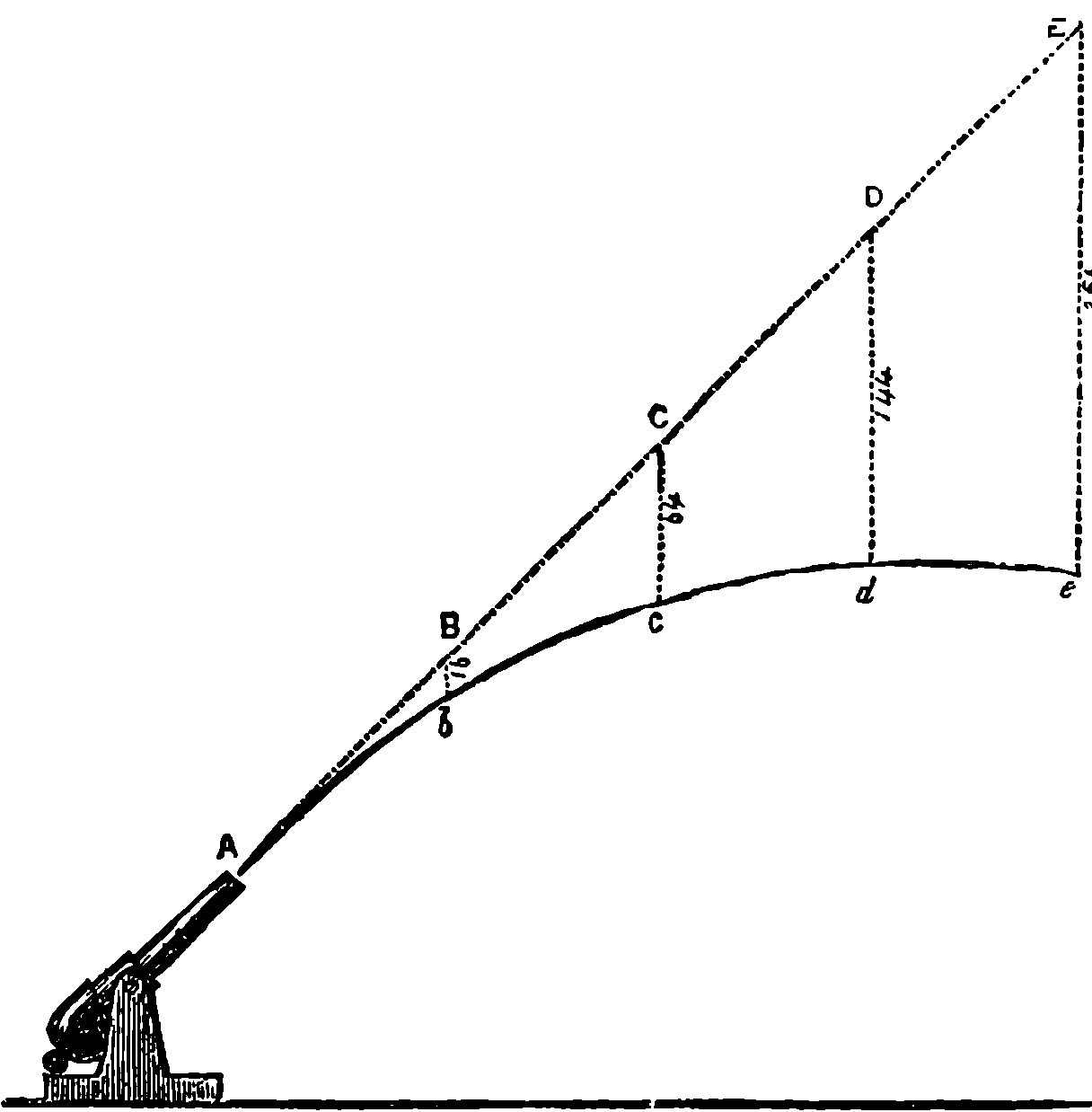
Fig. 80.—Trajectory of a Projectile.
The course or track of a projectile through the air after it leaves the gun is called the trajectory, and this has been studied both experimentally and theoretically, with interesting results. Assuming that the shot passed through empty space, or that the air offered no resistance to its passage, it would be very easy to trace the path of a projectile. Let us suppose that Fig. 80 represents a gun elevated at a high angle. The moment the projectile leaves the muzzle, gravity begins to act upon it, causing it to move vertically downwards with ever-increasing velocity until it finally reaches the ground; the onward uniform movement parallel to the axis of the piece being continued all the time. We could find the position of the projectile at the end of successive equal periods of time by drawing a straight line AC, a prolongation of the axis of the piece, or a line of the same inclination; on this we mark off equal distances representing by scale the velocity of the projectile per second, the points B, C, D, E being the positions the projectile would be in at the end of each successive second if gravity did not act. In order to bring the diagram within moderate compass, we suppose the projectile to have only the small velocity of 115 ft. per second. At the end of the first second it would be at B, but now suppose that gravity is allowed to act for one second, it would at the end of that time have fallen 16 ft. vertically below B and have arrived at b. Similarly we may set off by scale on verticals through C, D, and E distances representing 64 ft., 144 ft., and 256 ft. respectively. Because, for instance, the ball, without gravity acting, would at the end of 3 seconds be at D, where we may suppose its course arrested and gravity then allowed to act for 3 seconds to pull the ball down from its position of rest at D; at the end of this period, gravity alone acting, its position would be 144 ft. vertically below D, because gravity pulls a body that distance in 3 seconds, and the actual position 3 seconds after the ball had left the muzzle would be at d, after it had described the curved 175path A, b, c, d. Supposing d to be the highest point of the trajectory, another 3 seconds would bring the ball along a downward curve, and at the end of 6 seconds from the discharge it would be at a point on the same level as A. Now the complete curve would be symmetrical on each side of a vertical line through its highest point, and it would be in fact a regular parabola with its vertex at d.
The foregoing presupposes that the air offers no resistance to the passage of the projectile through it. The fact however is quite otherwise, for no sooner does the projectile begin its flight than its velocity is constantly diminished by the air’s resistance. Now this resistance is complex, depending upon a number of different conditions, the effect of which can be taken into account only by extremely complex calculations. Obviously it will vary according to the area of the section presented by the projectile to the line of its flight, and again by the shape of its front, for a pointed shot will cleave the air with less resistance than one with a flat front. Then the density of the air at the time will also enter into the calculation. The mass of the projectile and also its velocity, upon which depend its vis viva, energy, or power of overcoming resistance in doing work, will also have to be considered. Most complex of all is the law, or rather laws (i.e. relations), which connect the air resistance with the velocity; for this relation no definite expression has been found. It is a function of the velocity (known only by experiment under defined conditions), and varying with the velocity itself. Thus for velocities up to 790 ft. per second, it is a function (determined experimentally) of the second power or square of the velocity; between 790 ft. per second and 990 ft. per second the law of resistance is changed and becomes a function of the third power of the velocity; between 990 ft. and 1,120 ft. velocity the law again changes and is related to the sixth power of the velocity; between 1,120 ft. and 1,330 ft. the resistance is again related to the third power of the velocity; and with higher speeds than that last named it is again more nearly related to the square of the velocity. It will be seen that to calculate the path of a projectile is really a very difficult mathematical problem, and indeed one which can be solved only approximately when all the known data are supplied.
The air resistance to the motion of a projectile is much greater than before trial would be supposed. Let us take an experiment that has actually been recorded, in which a bullet three-quarters of an inch in diameter, weighing one-twelfth of a pound, was found to have a velocity of 1,670 ft. per second at a distance of 25 ft. from the gun, and this 50 ft. farther was reduced to 1,550 ft. per second. Now if the reader will calculate, according to the formula we have given above, the energy due to the bullet’s velocity at these points, he will find it must have done 500 foot-lbs. units of work in traversing the 50 ft., and as this could have been expended only in overcoming the resistance of the air, we learn that this last must have been equivalent to a mean or average pressure of 10 lbs. thrusting the bullet backwards.
It will be interesting to compare the difference in the trajectory of a projectile under defined conditions, worked out with the air resistance taken into account, compared with the trajectory when the air is supposed to be non-existent. We find an example of the former problem fully worked out by many elaborate mathematical formulæ in Messrs. Lloyd and Hadcock’s treatise on Artillery. The problem is thus stated:—“An 11–in. breech-loading howitzer” (a howitzer is a piece of ordnance used for firing 176at high angles) “fires a 600–lb. projectile with an initial velocity of 1,120 foot-sec. at an elevation of 20°. Find the range, time of flight, and angle of descent.” We shall calculate these points on the suppositions adopted with regard to Fig. 80, and with no higher mathematics than common multiplication and division.
It will have been observed that we supposed two motions that really take place simultaneously to take place successively and independently: one in the direction of the line of fire, due to the initial velocity; the other vertically downwards, due to the action of gravity, the final result being the same. This affords an excellent illustration of another of Newton’s laws of motion, and should be considered by the reader in this connection. The law itself admits of being stated in various ways, as thus:—“Whenever a force acts on a body, it produces upon it exactly the same change of motion in its own direction, whether the body be originally at rest or in motion in any direction with any velocity whatever—whether it be at the same time acted on by other forces or not.” Or again: “When two forces act in any direction whatever on a body free to move, they impress upon it a motion which is the superposition (or compounding) of those that it would receive if each force acted separately.” The law is given also in the following form (Thomson and Tait):—“When any forces act on a body, then, whether the body be originally at rest or moving with any velocity and in any direction, each force produces in the body the exact change of motion which it would have had had it acted singly on the body originally at rest.” In all of these expressions the word “forces” is used, and a very convenient word it is, but it may be noted in passing, nothing but a word; for it stands for no real self-existing things, since, apart from observed changes of motion in bodies, forces for us have no existence. Nevertheless, it is useful for the sake of abbreviating statements about changes of motion, to regard these actions as produced by imaginary agents—imagined for the time and for this purpose, and therefore vainly to be sought for in the realm of reality.
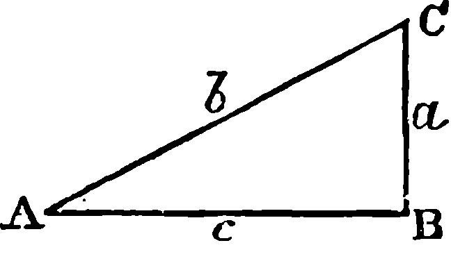
Fig. 81.—Diagram.
In dealing with the trajectory of the howitzer’s projectile through airless space we have no concern with its diameter nor with its weight. We use the little diagram, Fig. 81, to represent the motions,—c being a horizontal line, a, a vertical one, the angle at B is therefore a right angle, and we assume that at A to be 20°. Now, the most elementary geometry teaches us that every triangle having these angles will have the lengths of its sides in the same invariable proportions one to another whatever may be the size of the triangle itself, and it has been found convenient to calculate these proportions once for all, not merely for angle 20°, but for every angle up to 90°. Besides this, distinct names have been given to the proportions of every side of the triangle to each of the other two sides. Thus in the triangle before us, if we take a, b, and c to represent the numbers expressing the lengths of the sides against which they are placed, a divided by b, that is a ÷ b, or a/b, is called the sine of angle 20°, while c/b is named the cosine of that angle, etc. These therefore are numbers which are given in mathematical tables, and we find by these that sine 20° = 0·3420201, and cosine 20° = 0·9396926, and these with the 177initial velocity give us all the data we require. We may first find the time the projectile would take to reach the ground level, or strictly that of the muzzle of the gun at B. Taking t to stand for this time, we know that AC = 1,120 × t, but CB will be the distance that a body would fall from rest at C by the influence of gravity in that same time, t, and it is known by experiment that this distance is 16·1 feet multiplied by the square of the time from rest in seconds. We have now therefore the length of the line CB, and put a b = CB AC = 16·1 × t2 1,120 × t = sine 20° = ·3420201, and dividing numerator and denominator by t and multiplying the above 3rd and 5th expressions by 1,120, we have
16·1 × t = 1,120 × ·3420201
1,120 × ·3420201
and therefore t = = 23·7927 secs.
16·1
Having obtained the time, it will be easy to work out the lengths b and a as 26,648 ft. and 9114·1 ft. respectively; and as c/b = cosine 20°, we have c = 26,648 × ·9396926 = 25040·8 ft., which is the range. The trajectory will be a curve (parabola) symmetrical on each side of a vertical line half-way between A and B, and the length of this line within the triangle will be equal to half of a, and in half of 23·7927 seconds the projectile, supposed to move only along the line AC, would reach the point where this vertical axis intersects AC. If during this half-time it had been falling from rest at the same intersection, it would have reached a point below by a space just one quarter of CB (the spaces fallen through being as the squares of the times), and therefore at this its highest point its distance above AB would also be one quarter the length of a = 2278·525 ft., which distance is called the height of the trajectory; and the descending curve being in every respect symmetrical to the ascending branch, the angle at which this would be inclined to AB would be 20°, but in the opposite direction to BAC, while the velocity would be the same as at A. We may now compare these results with those calculated when the air resistance is taken into account:—
Without air With air
resistance. resistance. Difference.
Time of descent 23·7927 secs. 22·61 sec. –1·18 sec.
Angle of descent 20° 23° 49´ +3° 49´
Velocity of descent 1120 foot-secs. 868·8 foot-secs. –251·2 f.-s.
Range 25040·8 ft. 20,622 ft. –4418·8 ft.
Height of trajectory 2278·5 ft. 1989 ft. –288·5 ft.
With the air resistance the trajectory will no longer be a symmetrical curve: its highest point, instead of being on the vertical line midway between A and B, will be on one 1,050 ft. nearer to B than to A, and the descending branch will be steeper than the ascending. The total time, it will be observed, is less, although the final, and therefore the mean, velocity, is also less; but this shortening of the time is due to the trajectory itself being much less in length. The range of the projectile is decreased 178by 4,418 ft., or 1,473 yards, or more than four-fifths of a mile. The loss of velocity at the descent is very notable, and the reader will find it interesting to calculate the corresponding loss of energy by the formula already given.
The reader should now easily understand that the projectile from a rifle or gun discharged horizontally through airless space at the height of 16·1 ft. above a level plain would strike the ground in one second at a range or distance from the gun exactly equal to the initial velocity, or if the gun were on a tower and its axis 64·4 ft. above the plain, the range would then be 2V. It will be seen therefore that, corresponding to the range intended, there must be in general a certain inclination given to the axis of the piece in aiming, and this is done by means of the sights, one of which near the muzzle is usually fixed, while that next the breech is adjustable by sliding along an upright bar, which is graduated so that the proper elevation may be given for any required range. These graduations are made from experiments, and of course have reference only to some standard quantity and quality of ammunition and a standard of weight, shape, and material in the projectile. Sometimes large pieces of ordnance are laid by elevation in degrees, etc., marked on their mounting, the angles being taken from a table prepared for that particular gun and ammunition, from experiments at different ranges.
After these generalities about fire-arms we may enter upon certain particulars about the construction of some varieties, beginning with
THE MILITARY RIFLE.
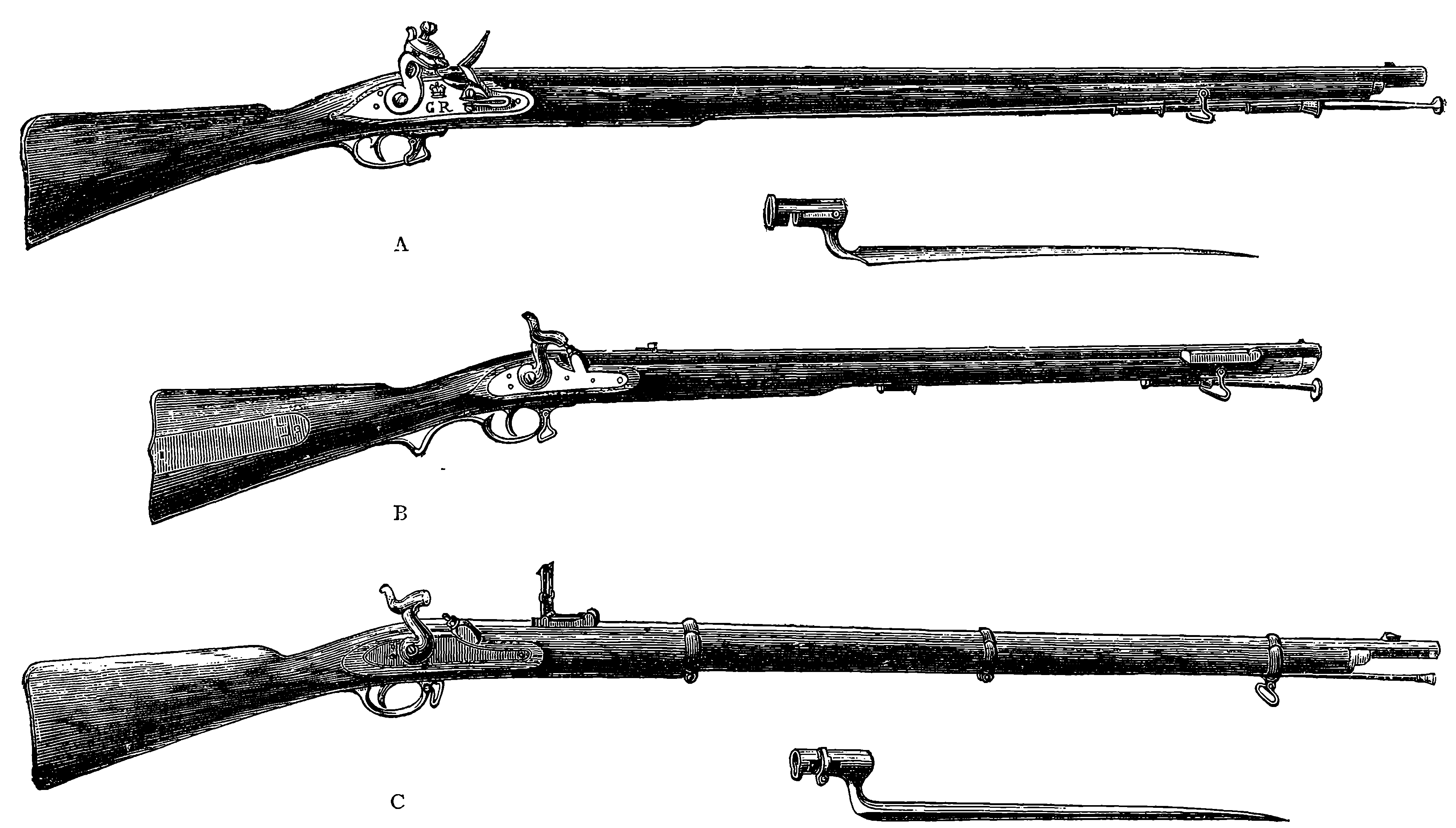
Fig. 82.—Muzzle-loading Musket and Rifles (obsolete patterns). A. Brown Bess and Bayonet; B. Brunswick Rifle; C. Enfield Rifle and Bayonet.
In Fig. 82 are represented the muzzle-loading musket and muzzle-loading rifles which formed the regulation weapons of the British infantry from the beginning of the century up to the year 1864. Somewhat slow in its earlier stages was the development of the modern military rifle from the old smooth bore musket with its flint-lock, which was the ordinary weapon of the British and other armies up to nearly the middle of this century. Partly, perhaps, owing to the inherent conservatism of government departments, and partly to the very serious outlay involved in arming all the troops of a nation with a new weapon, it has happened that many improvements in small arms were in use as applied to sporting guns, long before they were adopted in the regulation weapons of armies. The advance towards the modern arm of precision has been made along all the several directions that converge in the latest product, and it may be said that the most obvious of these are spiral rifling, breech-loading, and improved ammunition. The improvements in any one of these particulars would have been of little advantage unless the others had been kept in line with it. How long antiquated systems may continue in use may be illustrated by the case of the flint-lock, which was retained in the British army from the time it superseded the old match-lock, in the latter part of the seventeenth century, down to almost the middle of this present nineteenth. It is quite possible that not a few readers still in their fifties may never have seen a flint-lock outside of a museum, yet this was the firing apparatus of the weapon that used to be affectionately known to our soldiers as “Brown Bess,” and that for a century and a half continued the regulation arm of British troops helping Wellington 180to win his victories, and superseded by the percussion musket only in 1842. The “Brown Bess” of the earlier part of the century had a smooth-bore barrel of three-quarters of an inch diameter (0·753 inch), and 39 inches long; this musket weighed, with its bayonet, 11 lbs., 2 oz. The bullet was spherical, and made of lead, in weight a little over one ounce. The diameter of the bullet was slightly smaller than the bore of the barrel, because a closely fitting ball could not be used, on account of the great force required to push it home with a ram-rod. The bullet was therefore wrapped in loosely fitting material, called a “patch,” and this made the gun easy to load, even when the barrel was “fouled” by the solid residues that always remain after the explosion of gunpowder. “Brown Bess” was credited with a range of 200 yards, but its want of accuracy was such that the soldier was directed not to fire until he could see the whites of the enemies’ eyes. But in 1800 one or two British regiments were armed with the muzzle-loading rifle known as Baker’s, and again in 1835 these were provided with the Brunswick rifle. These regiments afterwards became known as the Rifle Brigade. The bullets in both cases were spherical, and as the earlier pattern had a seven-grooved barrel, there was so much difficulty in introducing the bullets into the muzzles that mallets had to be used. The bullet of the Brunswick rifle was encircled by a projecting band, which fitted into two rather deep grooves diametrically opposite to each other in the barrel. This bullet, wrapped in some slightly greased material, could be readily dropped into the muzzle, and rammed home without difficulty. Moreover, whereas in Baker’s rifle the grooves made only a quarter of a turn in the length of the barrel, the grooves of the Brunswick rifle made more than one complete turn. This was so much an improvement on “Brown Bess” that the effective range was more than doubled. For the rank and file of the infantry regiments the flint-lock smooth-bore musket was, however, the regulation weapon until 1842, when it was superseded by the percussion musket. The percussion-cap is now comparatively little used, as, since the introduction of cartridges containing their own means of ignition, it is rapidly becoming a thing of the past. The copper percussion-cap, in the form it still retains, was invented about 1816, and was universally adopted for sporting-guns a long time before it was used for the military weapon. In 1842 the percussion musket was definitely adopted as the weapon of the British army, but up to that date the flint-locks still continued to be made at Birmingham.
The barrel of the percussion musket then issued was shortly afterwards rifled, when about the year 1852 the Minié system was adopted, and the Government awarded to M. Minié, a Frenchman, the sum of £20,000 for the bullet he had invented. What the meaning of this improvement was may now be explained, and we must begin by mentioning the various forms of grooving, or, at least, such forms as found some approval during the present century, for grooved barrels had been tried long before. At first the grooves appear to have been intended merely to receive the fouling, and these were often made without any twist or spiral, but parallel to the axis of the barrel. The grooves are hollow channels of greater or less depth, and of various forms; square, triangular, rounded, or of such a form that the inner line of a section of the barrel would present the form of a ratchet wheel. The numbers of the grooves made use of have varied between two and twelve, or more, and different rates of twist, or numbers of turns of the spiral in the length of the barrel have been resorted to, 181these ranging from half a turn to twelve turns. The Brunswick rifle had been found wanting in accuracy, when at length in 1846 General Jacobs proposed the adoption of the conical bullet with projecting spiral ridges which fitted into grooves cut in the rifle barrel. The difficulty in using muzzle-loading rifles consisted in the force required to ram down the bullet, which had to adapt itself to the grooves, and fill them up so that the gases due to the explosion of the powder should not escape. If the bullet simply dropped into the bore of the rifle easily, it did not effectually fill the grooves, which then became channels of this windage, and if, on the other hand, the leaden bullet was made to fill the grooves from the muzzle, great force was required, and the time and effort expended in ramming the missile home, detracted enormously from the efficiency of the rifle as a military weapon. Mr. Lancaster produced rifles having a slightly oval, instead of a circular, bore, making, of course, the necessary twist within the barrel. A bullet of the corresponding section, but nearly globular, much as if the projecting belt of the Brunswick bullet had been laterally extended to its opposite poles, could be easily dropped in at the muzzle, without force being required to make it take grooves, the barrel being internally smooth throughout. It was, however, soon found that this easy-fitting ball allowed a considerable amount of windage, and the Minié system was definitely adopted, in which advantage was taken of a fact observed some years before by a French artillery officer, who found that an elongated leaden bullet, if hollowed out at the base, was so expanded by the pressure of the powder gases that the material was forced into the grooves of a rifle. Minié made his bullet elongated, pointed in front, and hollowed out part of its length by a conical space, the widest part of which was at the base, and was covered by a small iron cup, that, when driven inwards by the pressure of the gases, caused an expansion of the bullet by which the lead was forced into the grooves of the rifling. But the forces operating on the base of the bullet would at times cause the iron cup to cut the bullet in two, and propel the anterior portion only, leaving the base in the form of a ring clinging to the rifling. The military authorities had many comparative trials carried out between the smooth-bore percussion musket and the Minié rifle. The greater accuracy of the latter may be inferred from the results of practice made by men firing at a target 6 feet high and 20 feet broad; when at 100 yards distance, 74 hits out of 100 shots were made from the musket, against 94 from the rifle; and the superiority of the latter, at longer ranges, was increasingly marked. Thus at 260, 300, and 400 yards the respective percentages of hits were for the musket 42, 16, 4½, but for the same ranges the rifle gave 80, 55, 52.
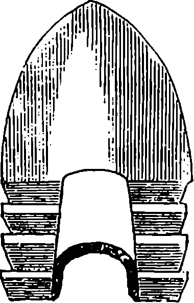
Fig. 83.—The Minié Bullet.
Curiously enough, the principle of the expanding bullet had been brought forward by the late Mr. W. Greener seventeen years before the government prize was awarded to M. Minié. Mr. Greener’s bullets were of an oval form, being half as long again as their diameter, with one end flattened where the lead was excavated in a narrowing hollow nearly through the bullet. In this opening was inserted the end of a tapering plug of hard metal, and when the rifle was fired this plug was driven home, and the lead thus expanded took the grooves, so preventing windage, and giving range and accuracy; while allowing the piece to be loaded with as 182much ease as the smooth-bore musket. The invention, though favourably reported on by the military authorities at the time, did not receive the attention it would seem to have deserved. However, in 1857, Mr. Greener’s claim of priority for the first suggestion of the expanding bullet was acknowledged by a government award of £1,000.
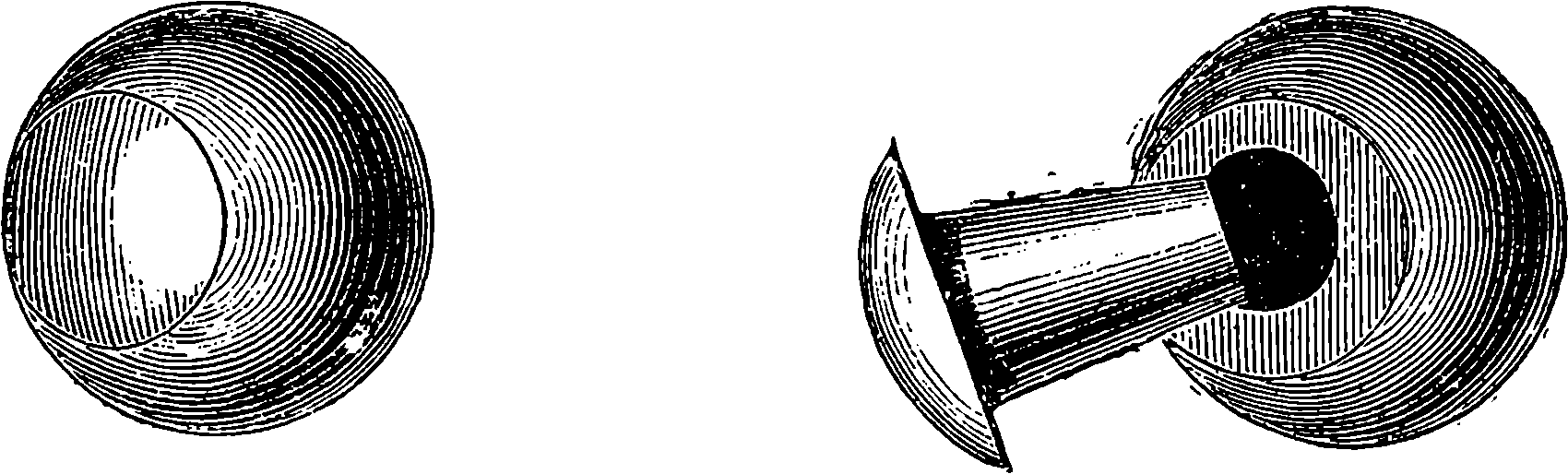
Fig. 84.—Greener’s Expanding Bullet.
Sir Joseph Whitworth, having been invited by the British military authorities to institute experiments with a view to producing the best type of rifle, with the help of the most perfect machinery, constructed the barrels with a polygonal bore, a plan which he had before adopted for large guns. The barrels were accurately bored out to a hexagonal section, and experiments were made to find what number of turns in the twist would give the projectile a sufficient rapidity of rotation to maintain it during its flight parallel to its axis. It was found that one turn in 20 inches was sufficient, and the projectile was made by machinery to fit accurately but easily into the rifled bore, so that it dropped into its place, and the loading could be expeditiously performed. The bullet was long, compared with the bore, which was made smaller than before, and it was found that the explosion caused it to expand sufficiently to fill up the corners of the hexagon, so that there was no loss from windage. The accuracy of aim of the Whitworth rifle was superior to that of any weapon of the kind that had, up to that time, been produced. When officially tried against the Enfield, its mean deviation at 500 yards range was only 4½ inches, while that of the Enfield at the same range was 27 inches. Mr. Whitworth had proved the advantages of using a small bore, an elongated bullet, and a sharp twist in the rifling; and it was acknowledged that as a military weapon his rifle was superior to all other arms of similar calibre that had before been produced. Some doubt appears to have been entertained, however, as to whether the mechanical perfection of the trial rifles could be maintained if they came to be manufactured on the large scale, and also as whether an adequate supply of the polygonal ammunition would be procurable when required. The Whitworth rifle was never adopted into the government service, and soon after these trials in 1857, the adoption of another type of weapon became imperative, as the results obtained by the Germans with their needle-gun, demonstrated the enormous advantages of a breech-loading rifle.
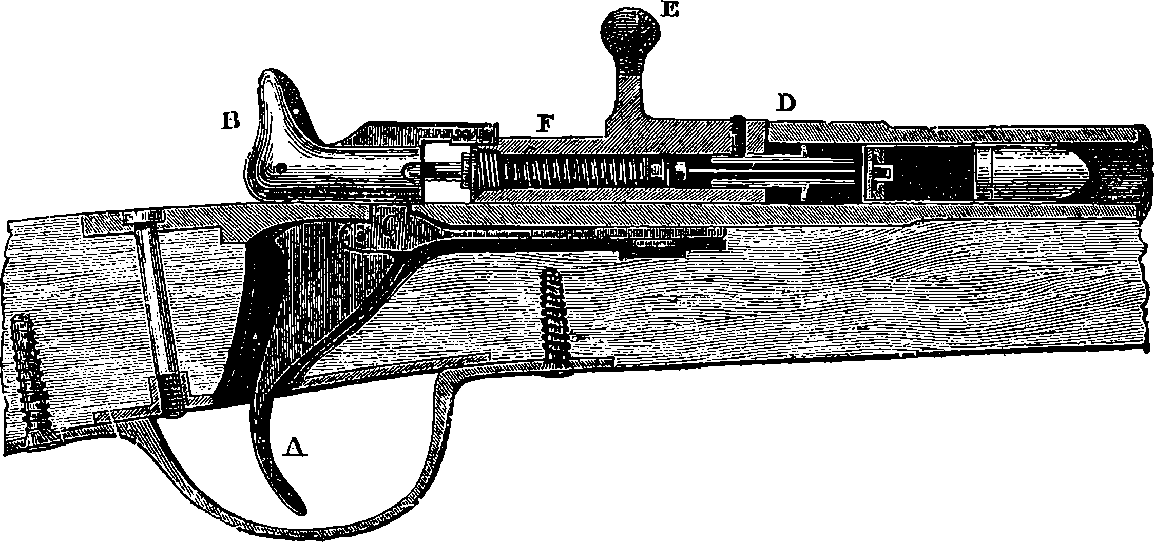
Fig. 85.—The Chassepot Rifle.—Section of the Breech.
The French then adopted the Chassepot rifle (so called after its inventor), which embodied the same principle as the needle-gun, but with improvements. This arm has a rifled barrel, with a breech mechanism of great simplicity, which is represented in section in Fig. 85. The piece marked B corresponds to what is called the “hammer” in the old lock used with percussion-caps, and the first operation in charging 183the rifle consists in drawing out B, as shown in the cut, until, by the spring, C, connected with the trigger, A, falling into a notch, the hammer, if we may so term it, is retained in that position. The effect of this movement is to draw out also a small rod attached to the hammer, and terminated in front by a needle, about ½ in. long, at the same time that a spiral spring surrounding the rod is compressed, the spring being fastened to the front end of the rod, and abutting against a screw-plug, which closes the hinder end of F, and permits only the rod to pass through it. The piece F, which is also movable, has projecting from its front end a little hollow cylinder, through the centre of which the needle passes, and this little cylinder has a collar, serving to retain its position, an india-rubber ring surrounding a portion of the cylinder, and forming a plug to effectually close the rear end of the barrel. It will be noticed that the cylinder is continued by a smaller projection, which forms a sheath for the point of the needle. The movable breech-piece, F, is provided with a short lever, E, by which it is worked. The second movement performed by the person who is charging the piece is to turn this lever from a horizontal to a vertical position, which thus causes the piece F to turn 90° about its axis, and then by drawing the lever towards him he removes the piece F from the end of the barrel, which, thus exposed, is ready to receive the cartridge. The cartridge contains the powder and the bullet in one case, the posterior portion containing also a charge of fulminate in the centre, and it is by the needle penetrating the case of the cartridge and detonating this fulminate that the charge is exploded. When the cartridge has been placed in the barrel, the piece F is pushed forward, the metallic collar and india-rubber ring stop up the rear of the barrel, and on turning the lever, E, into a horizontal position, the breech is entirely closed. If now the trigger be drawn, the hammer is released, and the spring carries it forward, at the same time impelling the needle through the base of the cartridge-case, where it immediately causes the explosion of the fulminate. The bullet is conical, and its base having a slight enlargement, the latter moulds itself to the grooves with which the barrel is rifled. When the piece has not to be fired immediately, the lever is not placed horizontally, but in an inclined position, in which the hammer 184cannot move forward, even if the trigger be drawn. The Chassepot has an effective range of 1,093 yards, and the projectile leaves the piece with a velocity of 1,345 ft. per second, the trajectory being such that at 230 yards the bullet is only 18 in. above the straight line. The piece can be charged and fired by the soldier in any position, and it was found that it could be discharged from seven to ten times per minute, even when aim was taken through the sights with which it is furnished, and fourteen or fifteen times per minute without sighting. The ordinary rifled musket, which this arm superseded, could only be fired twice in a minute, and could only be loaded when the soldier was standing up.
Other nations followed either by adopting as their infantry arm some form of breech-loader, or by converting their muzzle-loaders into breech-loaders as a temporary expedient, pending the selection of some more perfect type. When in 1864 a committee which had been appointed to investigate the question of proper arms for our infantry, recommended that that branch of the service should be supplied with breech-loaders, our Government, considering that no form of breech-loader had up to that time been invented which would unequivocally meet all the requirements of the case, wisely determined that, pending the selection of a suitable arm, the service muzzle-loaders should meanwhile be converted into breech-loaders. The problem of how this was to be done was solved by the gunmaker Snider, and in the “Converted Enfield” or “Snider” the British army was provided for a time with an arm satisfying the requirements of that period. This change of weapon was effected at a comparatively small outlay, for the conversion cost less than twenty shillings an arm. The breech action in the Snider consisted of a solid piece of metal which closed the breech end of the barrel, and, being hinged on the right-hand side parallel to the barrel, could be turned aside, making room for the insertion into the conically widened bore of a metallic cartridge case, invented by Colonel Boxer, which contained the projectile, the powder charge, and the means of ignition in itself. A short backward movement of the breech-lock caused a claw acting on the base of the spent cartridge case to withdraw it from the barrel, and then the reaction of a spring brought the breech-block back into position, after insertion of a new cartridge. This cartridge proved very effective in increasing the range and accuracy of the weapon. It should be mentioned that all the breech-loading mechanisms are provided with arrangements by which the metallic cases of the spent cartridges are automatically extracted from the barrel. The authorities having, in 1866, offered gunmakers and others handsome prizes for the production of rifles best fulfilling certain conditions, nine weapons were selected out of 104 as worthy to compete. No first prize was awarded, but the second was given to Mr. Henry, while Mr. Martini was seventh on the list. In order to obtain a weapon fulfilling all the requirements, a vast number of experiments were made by the committee appointed for that purpose, as to best construction of barrel, size of bore, system of rifling, kind of cartridge, and other particulars, and assistance was rendered by several eminent gunsmiths and engineers.
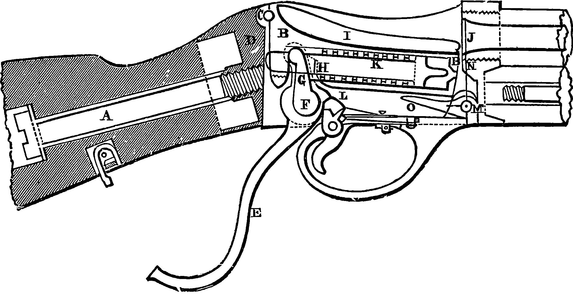
Fig. 86.—Section of Martini-Henry Lock.
After a severe competition it appeared that the best weapon would be produced by combining Henry’s system of rifling with Martini’s mechanism for breech-loading. The parts constituting the lock and the mechanism for working the breech, shown in Fig. 86, are contained in a metal case, to which is attached the woodwork of the stock, now constructed in two parts. To this 185case is attached the butt of the rifle by a strong metal bolt 6 in. in length, A, which is inserted through a hole in the heel-plate. The part that closes the breech—termed the “block”—is marked B. It turns loosely on a pin, C, passing through its rear end and fixed into the case at a level somewhat higher than the axis of the barrel. The end of the block is rounded off so as to form with the rear end of the case, D, which is hollowed out to receive it in a perfect knuckle joint. Let it be observed that this rounded surface, which is the width of the block, receives the whole force of the recoil, no strain being put on the pin, C, on which the block turns. In the experiments a leaden pin was substituted, and the action of the mechanism was not in the least impaired. This arrangement serves greatly to diminish the wear and the possibility of damage from the recoil. As the pin on which the block turns is slightly above the axis at the barrel, it follows that the block, when not supported, immediately drops down below the barrel. Behind the trigger-guard is a lever, E, working on a pin, F, fitted into the lower part of the case. To this lever is attached a much shorter piece called the “tumbler,” which projects into the case, G. It is this tumbler which acts as a support for the block, and raises it into its firing position or lowers it according as the lever, E, is drawn toward a firer or pushed forward. How this is accomplished will be readily understood by observing the form of the notch, H, in which the upper end of the tumbler moves. It will be noticed that the piece being in the position for firing, if the lever be pushed back, G slides away from the shallower part of the notch into the deeper, and the block accordingly falls into the position shown in the figure; and if again the lever is drawn backward, G acting on H will raise the block to its former position. The block or breech-piece is hollowed out on its upper surface, I, so as to permit the cartridge to be readily inserted into the exploding chamber, J. The centre of the block is bored out, and contains within the vital mechanism for exploding the cartridge, namely, a spiral spring, of which the little marks at K are the coils in section. These coils pass round apiece of metal called the “striker,” which is armed with a point, capable of passing through a hole in the front 186face of the block exactly behind the percussion-cap of the cartridge when the block is in the firing position. When the lever handle is moved forward, it causes the tumbler, which works on the same pin, to revolve, and one of its arms draws back the striker, compressing the spring in so doing, so that as the block drops down the point of the striker is drawn inwards. In this position the piece receives the cartridge into the chamber. The lever, E, being now drawn backward, the piece is forced into the notch, H, and the block is kept firmly in its place; besides this, there is a further compression of the spring by the tumbler, and in this position the spring is retained by the rest-piece, L, which is pushed into a bend in the tumbler. By pulling the trigger this piece is released, so that the tumbler can revolve freely, and relieve the pent-up spring, whose elasticity impels the striker forward, so that this enters the carriage directly. A very important and ingenious part of this arrangement is the contrivance for extracting the case of the exploded cartridge. The extractor turns on the pin, M, and has two arms pointing upwards, N, which are pressed by the rim of the cartridge pushed home into two grooves cut in the sides of the barrel. It has another arm, O, bent only slightly upwards and pointing towards the centre of the case, and forming an angle of about 80° with the above-mentioned upright arm; when, by pushing forward the lever, its short arm drops into the recess, the block, no longer supported, falls, and hits the point of the bent arm of extractor, so causing the two upright arms to extract the cartridge-case a little way.
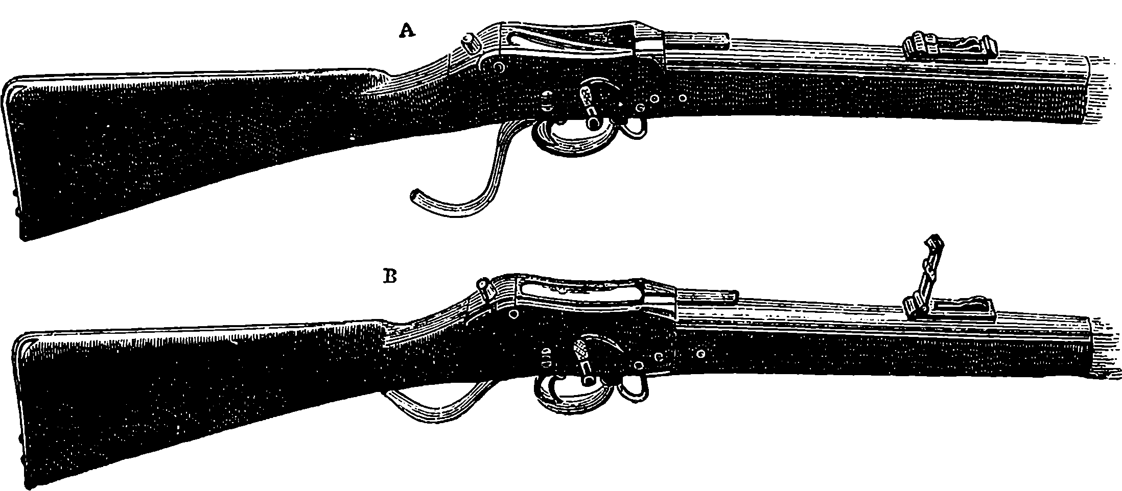
Fig. 87.—The Martini-Henry Rifle. A, ready for loading; B, loaded and ready for firing.
The barrel is of steel; the calibre is 0·451 in. It is rifled on Mr. Henry’s patent system. The section of the bore may be generally described as a heptagon with re-entering angles at the junctions of the planes, so that there are fourteen points of contact for the bullet, viz., one in the middle of each plane, and one at each of the re-entering angles. The twist of rifling is one turn in 22 in. The charge consists of 85 grains of powder, and a bullet weighing 480 grains, of a form designed by Mr. Henry. The cartridge is of the same general construction as the “Boxer” cartridge, used in the Snider rifle, but it is bottle-shaped, the diameter being enlarged from a short distance in rear of the bullet, in order to admit of its being made shorter, and consequently stronger, than would be otherwise possible. A wad of bees’-wax is placed between the bullet and powder, by 187which the barrel is lubricated at each discharge. The sword-bayonet to be used with this rifle is of a pattern proposed by Lord Elcho. It is a short sword, broad towards the point, and furnished on a portion of the back with a double row of teeth, so as to form a stout saw. It is so balanced as to form a powerful chopping implement, so that, in addition to its primary use as a bayonet, it will be useful for cutting and sawing brushwood, small trees, &c.
The following are the principal particulars of weight, dimensions, &c., of the Martini-Henry rifle:
Without bayonet 4 ft. 1 in.
Length of rifle With bayonet fixed 5 ft. 8 in.
Of barrel 2 ft. 9·22 in.
Calibre 0·451 in.
Rifling Grooves 7
Twist 1 turn in 22 in.
Weight Without bayonet 8 lbs. 7 oz.
With bayonet 10 lbs. 4 oz.
Bayonet Length 2 ft. 1½ in.
Weight without scabbard 1 lb. 8 oz.
Charge of powder 85 grains.
Weight of bullet 480 grains.
The rifle is sighted to 1,400 yards.
As an evidence of the accuracy of fire in this rifle, it may be stated that of twenty shots fired at 1,200 yards, the mean absolute deflection of the hits from the centre of the group was 2·28 ft. The highest point in the trajectory at 500 yards is rather over 8 ft. so that the bullet would not pass over a cavalry soldier’s head within that distance. The trajectory of the Snider at the same range rises to nearly 12 ft. The bullet will pass through from thirteen to seventeen ½ in. elm planks placed 1 in. apart at 20 yards distance; the number pierced by the Snider under similar circumstances being from seven to nine. As regards rapidity of fire, twenty rounds have been fired in 53 seconds; and one arm which had been exposed to rain and water artificially applied for seven days and nights, and had during that time fired 400 rounds, was then fired, without cleaning, twenty rounds in 1 minute 3 seconds.
Rifles of the Martini-Henry and Chassepot type were soon superseded, for as early as 1876 Switzerland had armed her troops with a magazine rifle of a smaller calibre than any then in use, and this weapon was found so effective that in a few years after every European nation had followed suit, as also had the United States and Japan, each country adopting some particular pattern of a weapon with certain modifications. Of these the Mannlicher and the Mauser are much used. A magazine rifle is one that can be fired several times successively without reloading. Like revolvers, the magazine arms repeat their fire, but instead of having several distinct firing chambers, they have but one, from which the empty cartridge cases are automatically extracted by the breech mechanism, for the magazine rifle is necessarily a breech-loader. The magazine rifle carries a supply of cartridges, which one after another are brought into the firing chamber by the simple action of the breech mechanism, so that the soldier is enabled to discharge several rounds in any position without reloading. The several varieties of the magazine rifle may be classed 188according to the position of the magazine. This may be: First, in the stock; second, under the barrel; third, in a box under the breech; or fourth, in a box above the breech. In the first and second variety the cartridges are in line in a tube, out of which they are moved on by a spiral spring, and this was the earlier form of the weapon. The box above or below the breech is the later development, and has the advantage of holding the cartridges lying side by side, and thus in a position in which they are not so liable to injure each other as in the tubular arrangements. Then, again, the movement of the cartridge in the breechbox in arriving at the firing chamber is much less than in the linear magazines, and the centre of gravity of the whole changes but little when the supply is exhausted. With any of the varieties of magazine a suitable modification of the mechanism may be adopted, so that the weapon can at will be used as a single firing rifle, but changeable in an instant to the magazine form. Again, the box magazine may be made as a fixture on the rifle, or it may be detachable. Commissions of military authorities had for several years been deliberating upon the best models for their respective nations, while Professor Hebler was working out his researches as to the best calibre for military rifles. Hebler published a work showing the great advantages of a bore one-third less in diameter than that commonly in use, which was about 0·45 inch, as in our Martini-Henry. The small-calibre rifle shoots straighter and hits harder than the large bore one, and the recoil is less, and so is the weight of the weapon. Lead is found to be too soft a material for the bullet of the small-bore rifles, as it does not keep in the rifling, which has a sharper turn than that in the older weapon; hence the bullets are now cased in steel or nickel. These bullets have remarkable power of penetration. Some will go through a steel plate 1¼ inch thick, making a clean hole in it, and the Lebel bullet penetrates 15 inches of solid oak, at a distance of 220 yards. Such a missile would, therefore, be capable of going completely through the bodies of several men or horses.

Fig. 88.—The Mannlicher Magazine Rifle.
The Germans, about 1888, adopted a magazine rifle known as the Mauser. It had a fixed tubular magazine for eight rounds below the barrel, and a breech mechanism of the Remington-Keene type. The French followed suit with their famous Lebel gun, the construction of which was long kept secret. It also has a fixed under barrel tubular magazine, and the cartridges used with it contain smokeless powder. It is said that a new gun of practically the same pattern has been adopted by Russia, but with a detachable magazine to contain five rounds. The Russian gun will also use smokeless powder. In England, a small-bore rifle of 0·303 inches calibre is now issued to all troops. It has an under breechbox magazine, modified from the Lee rifle. The box is detachable, so that the weapon could normally be used as a single loader, and the magazine attached only when required. But the British authorities have decided that the 189magazine box is to be attached to the weapon by a chain. The first issue of this pattern of rifle to British soldiers took place early in 1890. The Austrians are adopting the Mannlicher pattern, in which the magazine idea is embodied in a complete and practical form. This rifle has a fixed box magazine below the breech. From this box, in which the cartridges—five in number—lie side by side, they are fed up by springs as they are disposed of by the movement of the breech mechanism. The magazine is recharged by placing in it a tin case containing five cartridges, and the case drops out when all the cartridges have been fired. In this form there is of course no necessity for providing any mechanism for holding the magazine in reserve while the rifle is used as a single loader. As to calibre, the Austrian authorities follow other countries in adopting a small bore, namely, 0·315 inch. Italy has converted her single-fire Vetterli rifle into a magazine arm, with a box something like the Mannlicher, and Belgium has adopted a gun of the same type. The rate of fire from charged magazines of such guns as the “Lee,” “Mannlicher” and “Vetterli,” worked with the right hand without bringing the piece down from the shoulder is, for all of them, about one shot per second; but the time that is required to recharge the magazines varies much according to the contrivance used. The number of rounds the magazine of a rifle is capable of containing when fully charged is from 5 to 12, or more, according to the difference of system. It is considered that in the detachable Lee or the quick recharging Mannlicher five rounds are ample for use at a critical moment.
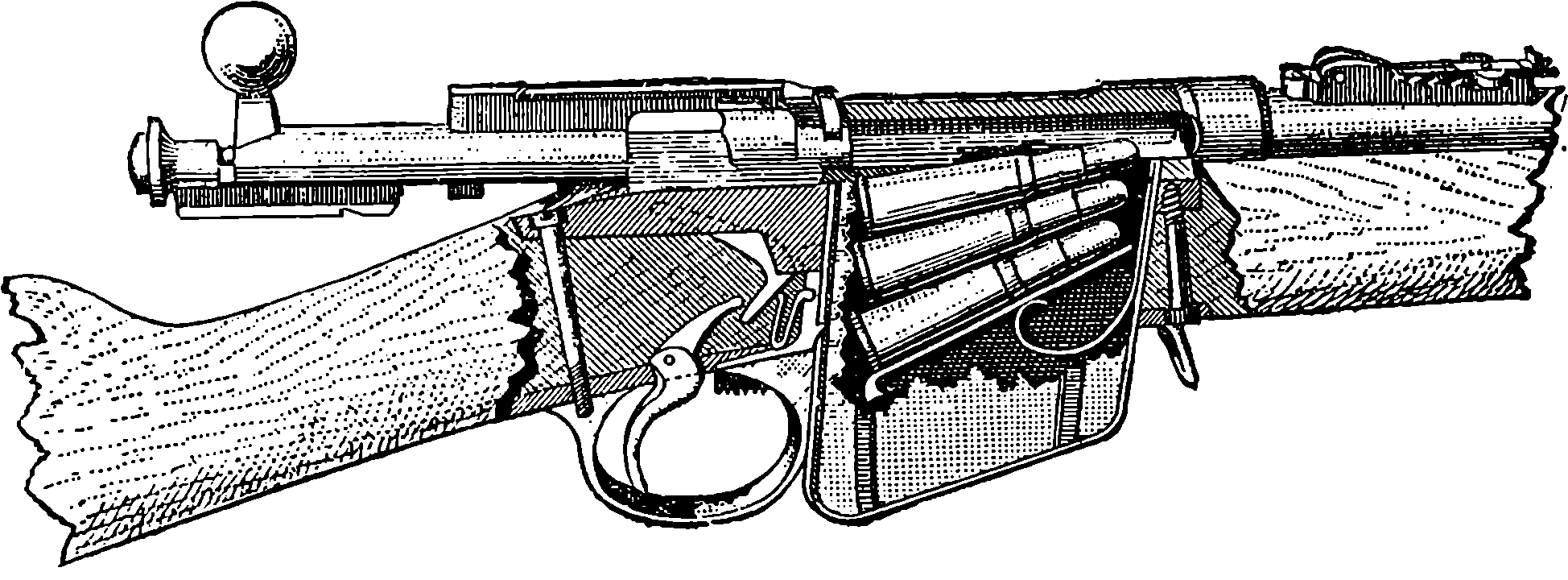
Fig. 89.—The Magazine and Breech of the Mannlicher Rifle.
The calibre of the military rifle has been decreased with almost every new pattern adopted. Thus, while the old “Brown Bess” had a calibre of 0·75 inch, in the last issue of it the bore was reduced to 0·693 inch; the Enfield (1852) had a bore of 0·577 inch; the Martini-Henry, 0·451 inch, which, in a newer pattern adopted in 1887, was reduced to 0·400 inch; and, finally, in the Lee-Metford, the calibre is only 0·303 inch. A similar consecutive reduction of bores has taken place in the rifles adopted by other countries, and one of the latest type, issued for the use of the United States Navy, has a bore of only 0·236 inch, and it is even expected that a still smaller one will become general. The advantage of the narrow and lighter projectile is that while it has a higher initial velocity with a given charge, its flight is less checked by the resistance of the atmosphere, the section it presents being so much less. Thus the bullet of 0·236 inch diameter has a section little more than one-fourth that of the 0·45 inch 190bullet. The difference is well shown in the comparative heights of the trajectory (or path of the bullet) of the Martini-Henry 0·450 inch bullet, and that of the 0·303 inch Lee-Metford (the latter with cordite ammunition); for at a range of 1,000 yards the former reaches to 48 feet above the line of sight, while the latter rises to only 25 feet.
Some form of repeating or magazine rifle has now been adopted by all the most important nations of the world. The number of shots contained in the magazines varies from 5 to 12. In the British detachable box magazine there are ten charges. The calibres of the barrels range in the infantry patterns of different nations from 0·256 inch to 0·315 inch; the explosive used in every case is some kind of smokeless powder, and this, in the cartridge for the Lee-Metford, is cordite. The bullets are not made simply of lead, but of lead coated with a harder metal or alloy such as steel, cupro-nickel, nickel steel, or they consist entirely of some of these alloys.
Although the magazine rifle is now the regulation weapon of the infantry of all great armies, it is not improbable that at no distant future it maybe superseded by one in which, as in certain machine guns, the force of the recoil will be used for actuating the breech and lock movements. Many patents have already been taken out for rifles on this principle, and several patterns have actually been constructed, in which a merely momentary contact of the breech-piece with the end of the barrel is sufficient; the recoil of the barrel with the reaction of a spring performs all the requisite movements with such rapidity that an amazing speed of firing has been obtained. It is said that such an automatic gun can send forth bullets at a perfectly amazing rate. Of course the mechanism of such a gun is somewhat intricate, and it is impossible to explain its construction and action without a great number of diagrams and much description.
RIFLED CANNON.
Having briefly sketched in the foregoing section the development of the military rifle from such weapons as our own “Brown Bess,” down to the repeating or magazine rifle, we now purpose to adopt a similar course with regard to ordnance, giving also some particulars of the methods of manufacture, etc., and following in general the order of history.
Naturally there is nothing that accelerates progress in warlike inventions so much as the exigences of war itself. This is well exemplified in circumstances attending the Crimean War, which was waged in 1854 by England and France in alliance against Russia. The desire of having ships that could run the gauntlet of the heavy guns mounted on Russian forts led to the construction of La Gloire and other armour-plated vessels, as we have already seen, and a suggestion of the French Emperor, as to improving metal for guns, made to Mr. Bessemer, led incidentally but ultimately to the great revolution in the manufacture of steel, although it is true that Krupp of Essen had begun to produce small cast-steel ordnance as early as 1847. But what determined the necessity for rifled ordnance was more particularly the greater comparative effects obtained by the muzzle-loading rifles over the field artillery 191then in use in the several engagements that took place in the Crimea, especially in the battle of Inkerman (1854). The rifles so much surpassed in accuracy at long ranges the smooth-bore field-pieces firing spherical projectiles, that field artillery was on the point of losing its relative importance, and even in the matter of range the latter lost so much by windage that the men serving the artillery could sometimes be leisurely picked off by the rifle sharp-shooters. Inventors were soon at work on devising methods of increasing the accuracy of ordnance fire with both light and heavy pieces, and before the end of the war some cast-iron guns rifled on Lancaster’s plan had been mounted on forts and in ships, without proving very successful except in regard to increase of range when elongated pointed projectiles were used with them.
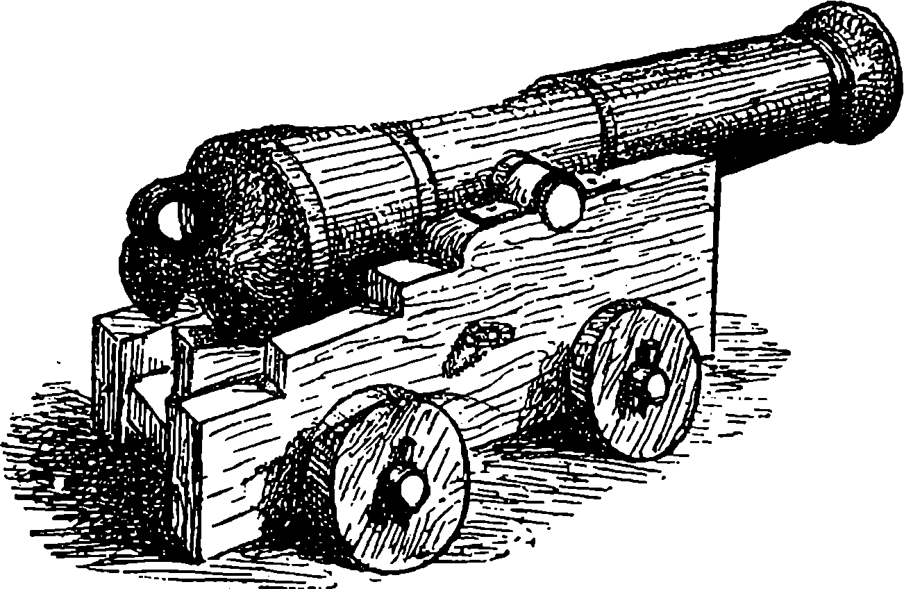
Fig. 90.—32–pounder, 1807.
Now let us see of what kind was the ordnance used for some years after the middle of the century, in order that we may be the better able to appreciate the progress that has since been made. Ordnance is, as already noticed, of several species, as guns mounted on fortresses, naval guns, siege guns, field-guns, etc., and the size of the pieces under each of those heads is distinguished sometimes in one, sometimes in another of three different ways. We may name it by the weight of the gun itself in tons or hundredweights, as “a 35–ton gun,” etc.; or by the weight of its projectile, as “a 68–pounder,” etc.; or by its calibre, that is the diameter of its bore, as “a 4–inch gun,” etc. We may take the naval guns with which Nelson won his battles (Trafalgar, 1807) as representative of all except field ordnance up to about 1856. They were all made of cast iron, threw spherical projectiles, and were very rudely mounted. The gun most commonly mounted on board our ships of war was the 32–pounder, weighing 32 cwt., shown with its carriage in Fig. 90. The carriage was of wood, and consisted of two side pieces joined back and front by two transverse pieces and carried by four low wooden wheels. The trunnions of the gun fitted into bearings at the top of the side-pieces, and were secured by iron plates that passed over them in a semi-cylindrical form and were bolted down to the wood. The position of the trunnions on the gun was always such that the breech end of the gun preponderated, being supported on an adjustable wooden wedge; and when the muzzle of the gun had to be lowered, this was done by raising the breech end with handspikes and pushing in the wedge so far as to prevent the 192breech from dropping down again. There was a vent or narrow passage to contain a train of powder from the touch-hole at the upper part of the breech to the rear of the charge. When the gun was fired, with its muzzle protruding a little way out of the port-hole, the recoil would trundle it inwards about its own length, when its course would be stayed by a thick rope attached to the sides of the vessel; and by other tackle it would be kept in position until loaded, when it would be allowed to roll back, or would be drawn by ropes and pulleys out to the port-hole, and by the same means such lateral inclination as might be required could be given. This last adjustment was called training the gun. A 32–pounder required the services altogether of a dozen or fourteen men, but these by virtue of constant drill would learn to handle the clumsy machine with a certain amount of expedition. If we except a notch on the highest point of the muzzle, the pieces were devoid of anything of the nature of sights, though sometimes marks were made on the adjustable wedge under the breech to correspond with certain elevations. Nor were sights required; for the mode of fighting then was to get quite close to the adversary’s ship and pour in a broadside by firing simultaneously all guns on the enemy’s side when they had been trained (by rough methods), so as to concentrate their effect as much as possible on one point of the antagonist. Nelson’s famous ship the Victory carried a few larger guns than the 32–pounders, namely, two 68–pounders, called carronades (from having first been cast at Carron in Scotland), and some 42–pounders. The 32– and 42–pounders numbered together thirty, and there were also as many 24–pounders, with forty 12–pounders. These were all simply cast of the required dimensions, and were not made with the one single improvement which after two centuries’ use of cast-iron guns had been introduced into France about fifty years before, namely, the boring of the chase out of a solid casting.
On the outbreak of the Crimean War (1854) the minds of many inventors were occupied by the problem of ordnance construction, and this also engaged the attention among others of two of the most eminent British mechanical engineers of the day. These were Sir W. Armstrong and Sir J. Whitworth, who, with others, were invited by our War Department to submit the best models of field and heavy guns their skill was severally able to produce. Two years afterward, Sir W. Armstrong had, after many experiments, completed a gun of 1·88 in. calibre. This had a forged steel barrel 6 feet in length; but it was only after eight such forgings had been bored and rejected on account of flaws revealed only by the boring that a sound barrel was at length obtained. This barrel was strengthened on the outside by jackets made from coils of wrought iron bars welded into a piece and shrunk on while hot (of which process we shall have something more to say presently); the barrel was rifled with many shallow grooves, and the pointed projectile, 3 calibres long, was made of lead, for which afterwards iron coated with lead was substituted. This gun was a breech-loader, the breech being closed by a block let into a slot after loading, and then pressed against the barrel by some turns of a screw which advanced parallel to the axis of the piece, and was made hollow for loading through, before the closing block was put in. In a trial of the various pieces ready in 1857, it was found that the Armstrong gun made as just described had an accuracy and range immensely greater than any weapon that had ever been tested, and the Government authorities approved of the system of construction, except that they preferred muzzle-loading pieces to breech-loading, as being simpler in 193action, more easily kept in repair, and cheaper in original cost and ammunition.
When Sir Joseph Whitworth’s gun was, in 1863, submitted to a competitive trial against the Armstrong, as to their endurance and mode of ultimate failure when fired with ever-increasing charges of powder and shot, at the forty-second round the Armstrong breech-loader split, and at the sixtieth the Armstrong muzzle-loader had one of its coils cracked; while it was not until the ninety-second round that the Whitworth gun burst violently into eleven pieces. These competing guns were 12–pounder field-guns weighing 8 cwts., and from each 2,800 regulation rounds had been fired before they were subjected to the bursting proofs. The result of these trials being that the authorities considered that steel was not then sufficiently reliable, and they decided to adopt the system of building up rifled guns with iron jackets over an inner tube of steel. Sir Joseph Whitworth made his guns entirely of steel, and they were striking examples of beautiful and accurate workmanship. His system of rifling consisted in forming the bore of the gun so that its section is a regular hexagon, and the projectile is an elongated bolt with sides exactly fitting the barrel of the gun: the projectile is, in fact, a twisted hexagonal prism. Fig. 91 shows at the left-hand side the section of the barrel, and on the right we see the form of the projectile on a smaller scale, this last representing, in fact, the exact size and shape of the bullet of the Whitworth rifle mentioned on another page. Sir Joseph’s guns were muzzle-loaders, and they were remarkable for their long range and accuracy of fire. One of these guns, with a charge of 50 lbs. of gunpowder, threw a 250–lb. shot a distance of nearly six miles, and on another occasion a 310–lb. shell was hurled through the air, and first touched the ground at a distance of more than six and a quarter miles from the gun. These distances are greater than any to which shot or shell had previously been thrown.
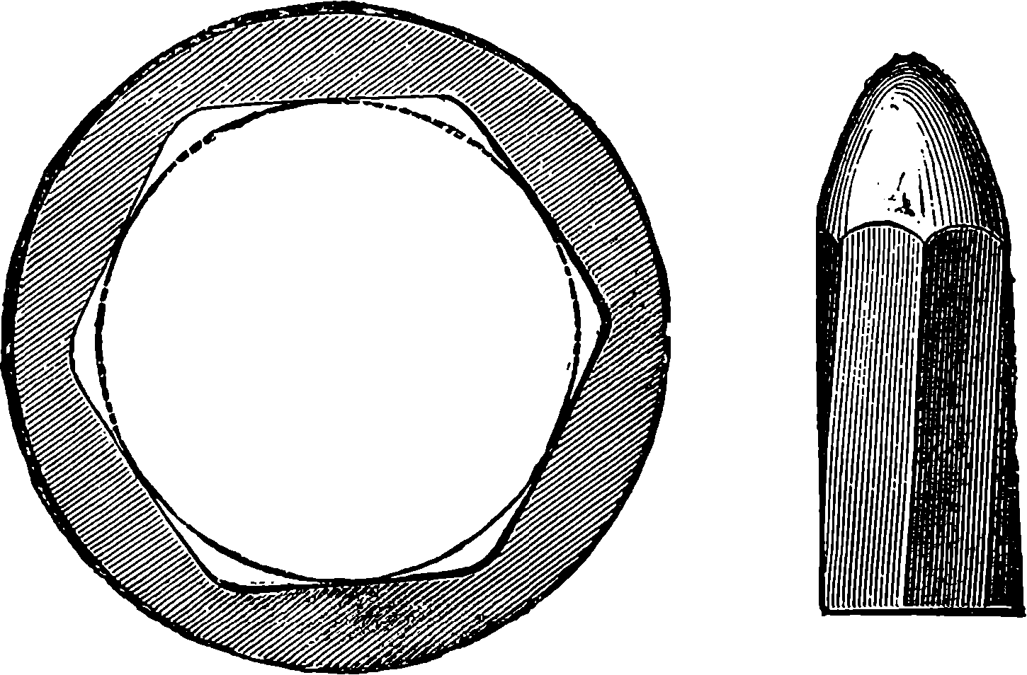
Fig. 91.—Whitworth Rifling and Projectile.
As the material of these Whitworth guns was very costly, and very perfect workmanship was required in the formation of the barrel and the shots, the expense attending their manufacture and use was much greater than that incurred in the case of the Armstrong guns. Sir W. Armstrong’s 194estimate for a 35–ton gun was £3,500, and Sir J. Whitworth’s, £6,000. The gun, as constructed at Woolwich on Mr. Fraser’s plan, was estimated to cost £2,500. The first cost of a gun is a matter for consideration, since each piece, even the strongest, is able only to fire a limited number of rounds before it becomes unsafe or useless. It appears that no cannon has yet been constructed capable of withstanding without alteration the tremendous shocks given by the explosion of the gunpowder, and these alterations, however small at any one discharge, are summed up and ultimately bring to an end what may be termed the “life of the piece.”
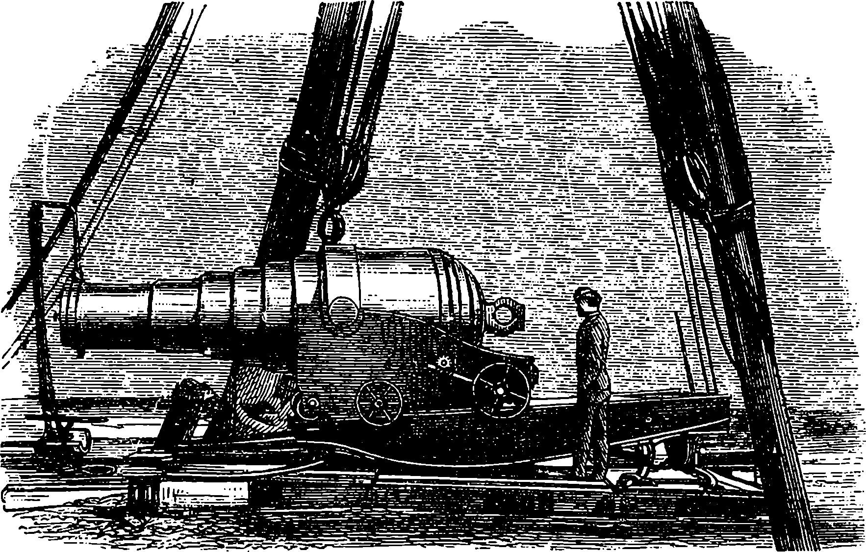
Fig. 92.—600–pounder Muzzle-loading Armstrong Gun.
About the year 1858 Sir William Armstrong (afterwards Lord Armstrong) established at Elswick, Newcastle-on-Tyne, a manufactory of ordnance, which has since developed into the great arsenal now so well known all over the world. Here all the resources of science have been applied to the problems of artillery, and experiments carried on with a prodigality of cost and promptness of execution impossible at a government establishment trammelled with official regulations. Here, and also at Woolwich, our national ordnance factory, guns have since always been constructed on the building-up plan advocated by Sir W. Armstrong, whose principle consists in disposing of the fibre of the iron so as best to resist the strains in the several parts of the gun. Wrought iron being fibrous in its texture has, like wood, much more strength in the direction of the grain than across it. The direction of the fibre in a bar of wrought iron is parallel to its length, and in that direction the iron is nearly twice as strong as it is transversely. A gun may give way either by the bursting of the barrel or by the blowing out of the breech. The force which tends to produce the first effect acts transversely to the axis of the gun; hence the best way to resist it is to wrap the iron round the barrel, so that the fibres of the metal encircle it like the hoops of a cask. The force which tends to blow out the breech is best resisted by disposing the fibres of the iron so as to be parallel to the axis of the gun; hence Sir W. Armstrong makes the breech-piece from a solid forging with the fibre in the required direction. But the 195Elswick building-up principle involves much more than the direction of the fibres of the iron, for each coil or jacket, after having its spires welded together, was bored out on a lathe, and the exterior of the part of the gun on which it was to be placed was also turned with the utmost exactness, so that when the enveloping piece was heated to a certain temperature and in this state brought into position, it would in cooling compress the parts it encircled just to that degree which careful calculations showed would best strengthen the gun without unduly straining the metal at any part. The Elswick guns being built up of several superimposed jackets of calculated lengths and thicknesses, the means was afforded of distributing the tensions throughout the whole mass of metal to the best advantage. In the simpler form, arranged by Mr. Fraser, and for the sake of economy adopted by the authorities at Woolwich in 1867, the greater part of the benefit derivable from adjustment of tension was no doubt sacrificed to cheapness of manufacture. These, and also the forms of Armstrong guns that have not yet been described, ceased to be made after 1880, by which time steel had replaced iron in every part of the construction and fittings of guns, and muzzle-loading had been definitely abandoned in favour of breech-loading.
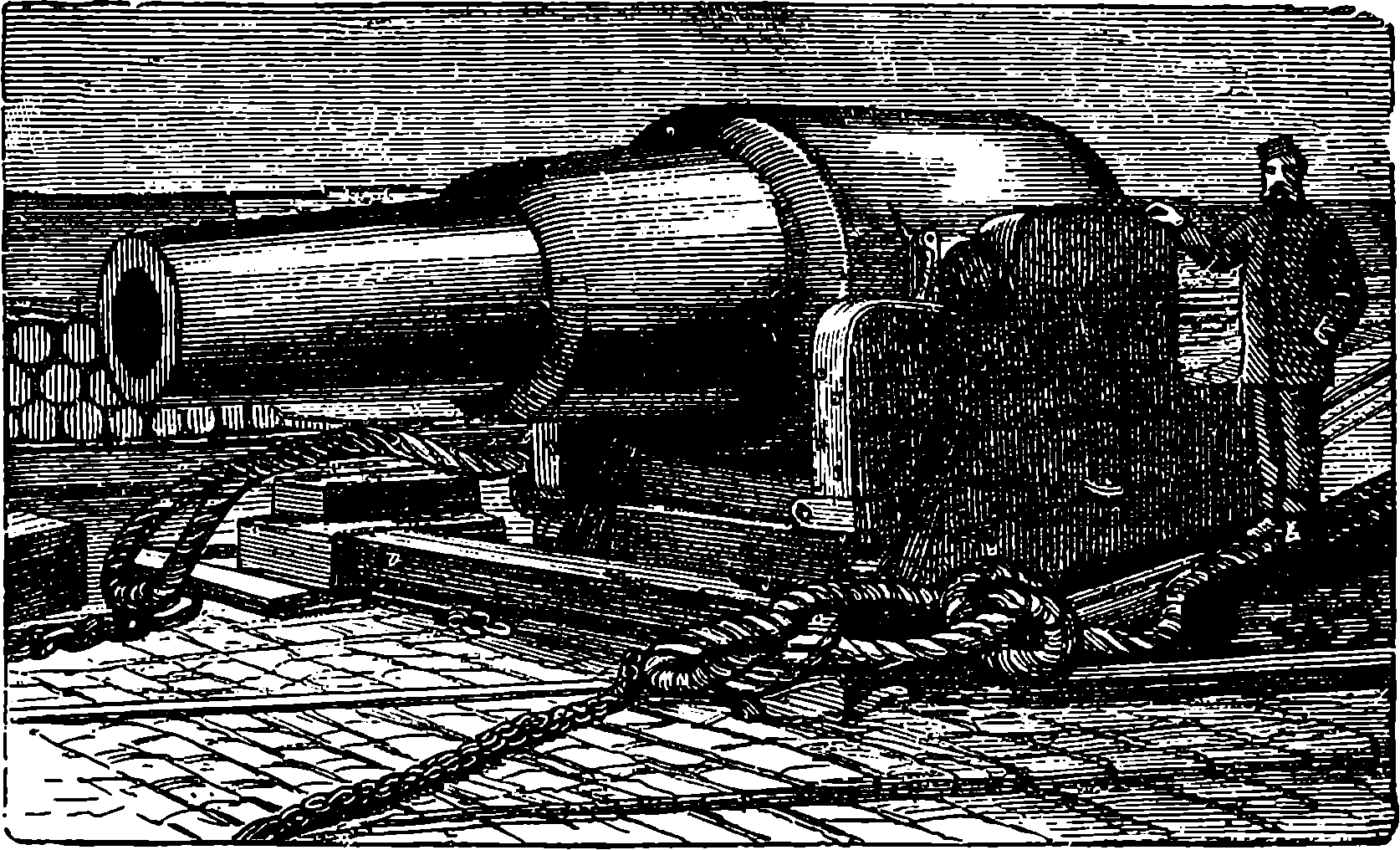
Fig. 93.—35–ton Fraser Gun.
Now, in 1874, when the first edition of the present work was in preparation, the Fraser-Woolwich guns were in full vogue, being spoken of by the public press as the ne plus ultra of artillery construction in size, efficiency, and economy. When, accordingly, the author had been privileged to visit the arsenal and witness the production of these guns in every stage of their manufacture, he wrote a description of it which is here retained as printed at the time, seeing that it may not be without historical interest, particularly since great numbers of these guns must still be extant, mounted on our forts in various parts of the world, and seeing also that the description of the simpler formations may render more easily to be understood future references to similar operations in gun-making as have been retained in the later developments. Of course, the following description was written in the present tense, and therefore in perusing it the reader must constantly bear in mind that the guns with 196which our ships of war have since been equipped are in every respect entirely different from
The Fraser-Woolwich Guns, 1867–1880.
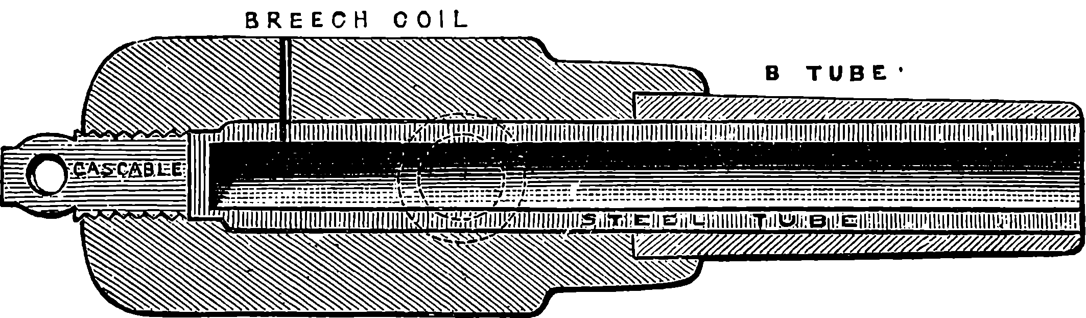
Fig. 94.—Section of 9 in. Fraser Gun.
Until the year 1867 the guns made at Woolwich were constructed according to the original plan proposed by Sir W. Armstrong, and on this system one of the large guns consisted of as many as thirteen separate pieces. These guns, though unexceptionable as to strength and efficiency, were necessarily so very costly that it became a question whether anything could be done to lessen the expense by a simpler mode of construction or by greater economy in the material. The problem was solved in the most satisfactory manner by Mr. Fraser, of the Royal Gun Factory, who proposed an important modification of the original plan, and the adoption of a kind of iron cheaper than had been previously employed, yet perfectly suited for the purpose. Mr. Fraser’s modification consisted in building up the guns from only a few coils, instead of several, the coils being longer than Sir W. Armstrong’s, and the iron coiled upon itself two or even three times: a plan which enabled him to supersede the breech-piece, formerly made in one large forging, by a piece formed of coils. In order to perceive the increased simplicity of construction introduced by Mr. Fraser, we need but glance at the section of a 9 in. gun constructed according to his system, Fig. 94, and remember that a piece of the same size made after the original plan had ten distinct parts, whereas the Fraser is seen to have but four. Compare also Figs. 92 and 93. We shall now describe the process of making the Fraser 9 in. gun. The parts of the gun as shown in the section, Fig. 94, are: 1, the steel barrel; 2, the B tube; 3, the breech-coil; 4, the cascable screw. The inner steel barrel is made from a solid cylinder of steel, which is supplied by Messrs. Firth, of Sheffield. This steel is forged from a cast block, the casting being necessary in order to obtain a uniform mass, while the subsequent forging imparts to it greater solidity and elasticity. After the cylinder has been examined, and the suitable character of the steel tested by trials with portions cut from it, the block is roughly turned and bored, and is then ready for the toughening process. This consists in heating the tube several hours to a certain temperature in an upright furnace, and then suddenly plunging it into oil, in which it is allowed to remain for a day. By this treatment the tenacity of the metal is marvellously increased. 197A bar of the steel 1 in. square previous to this process, if subjected to a pull equal to the weight of 13 tons, begins to stretch and will not again recover its original form when the tension is removed, and when a force of 31 tons is applied it breaks. But the forces required to affect the toughened steel in a similar manner are 31 tons and 50 tons respectively. The process, unfortunately, is not without some disadvantages, for the barrel is liable to become slightly distorted and even superficially cracked. Such cracks are removed by again turning and boring; the hardness the steel acquires by the toughening process being shown by the fact that in the first boring 8¼ in. diameter of solid steel is cut out in 56 hours, yet for this slight boring, in which merely a thin layer is peeled off, 25 hours are required; and lest there should be any fissures in the metal, which, though not visible to the eye, might make the barrel unsound, it is filled with water, which is subjected to a pressure of 8,000 lbs. per square inch. If under this enormous pressure no water is forced outwards, the barrel is considered safe. It is now ready to have the B tube shrunk on it.
The B tube, like certain other portions of these guns, is constructed from coiled iron bars, and this constitutes one great peculiarity of Sir W. Armstrong’s system. It has the immense advantage of disposing the metal so that its fibres encircle the piece, thus applying the strength of the iron in the most effective way. The bars from which the coils are prepared are made from “scrap” iron, such as old nails, horse-shoes, &c. A pile of such fragments, built up on a wooden framework, is placed in a furnace and intensely heated. When withdrawn the scraps have by semi-fusion become coherent, and under the steam hammer are soon welded into a compact mass of wrought iron, roughly shaped as a square prism. The glowing mass is now introduced into the rolling-mill, and in a few minutes it is rolled out, as if it were so much dough, into a long bar of iron. In order to form this into a coil it is placed in a very long furnace, where it can be heated its entire length. When sufficiently heated, one end of the bar is seized and attached to an iron core of the required diameter, and the core being made to revolve by a steam engine, the bar is drawn out of the furnace, winding round the core in a close spiral, so that the turns are in contact. The coil is again intensely heated, and in this condition a few strokes of the steam hammer in the direction of its axis suffice to combine the spires of the coil into one mass, thus forming a hollow cylinder.
The B tube for the 9 in. gun is formed of two double coils. When the two portions have been completely welded together under the steam hammer, the tube, after cooling, is roughly turned and bored. It is again fine bored to the required diameter, and a register of the diameter every few inches down the bore is made. These measurements are taken for the purpose of adapting most accurately the dimensions of the steel barrel to the bore of the B tube, as it is found that perfect exactness is more easily obtained in turning than in boring. The steel barrel is therefore again turned to a size slightly larger than the bore of the B tube, and is then placed muzzle end upwards, and so arranged that a stream of water, to keep it cool, shall pass into it and out again at the muzzle, by means of a syphon, while the B tube, which has been heated until it is sufficiently expanded, is passed over it and gradually cooled.
If now the B tube were allowed to cool spontaneously, its ends would, by cooling more rapidly than the central part, contract upon the steel barrel and grip it firmly at points which the subsequent cooling would tend to draw nearer together longitudinally, and thus the barrel would be subjected 198to injurious strains. In order to prevent this, the B tube is made to cool progressively from the breech end, by means of jets of water made to fall upon it, and gradually raised towards the muzzle end, which has in the meanwhile been prevented from shrinking by having circles of gas-flames playing upon it.
The breech-coil, or jacket, is formed of three pieces welded together. First, there is a triple coil made of bars 4 in. square, the middle one being coiled in the reverse direction to the other two. After having been intensely heated in a furnace for ten hours, a few blows on its end from a powerful steam hammer welds its coils perpendicularly, and when a solid core has been introduced, and the mass has been well hammered on the sides, it becomes a compact cylinder of wrought iron, with the fibres all running round it. When cold it is placed in the lathe, and the muzzle end is turned down, leaving a shoulder to receive the trunnion-ring. The C coil is double, welded in a similar manner to the B coil, and it has a portion turned off, so that it may be enclosed by the trunnion-ring.
The trunnion-ring is made by punching a hole in a slab of heated iron first by a small conical mandrel, and then enlarging by repeating the process with larger and larger mandrels. The iron is heated for each operation, and the trunnions are at the same time hammered on and roughly shaped—or, rather, only one has to be hammered on—for a portion of the bar which serves to hold the mass forms the other. The trunnion-ring is then bored out, and after having been heated to redness, is dropped on to the triple breech-coil which is placed muzzle end up, and the turned end of the C coil (of course, not heated) is then immediately placed within the upper part of the trunnion-ring. The latter in cooling contracts so forcibly as to bind the ends of the coils together, and the whole can thus be placed in a furnace and heated to a high temperature, so that when removed and put under the steam hammer, its parts are readily wielded into one mass. The breech-coil in this state weighs about 16 tons; but so much metal is removed by the subsequent turnings and borings, that it is reduced to nearly half that weight in the gun. It is then turned in a lathe of the most massive construction, which weighs more than 100 tons. Fig. 34, page 95, is from a drawing taken at Woolwich, and shows one of the large guns in the lathe. No one who witnesses this operation can fail to be struck with the apparent ease with which this powerful tool removes thick flakes of metal as if it were so much cheese. The projections of the trunnions prevent the part in which they are situated from being finished in this lathe, and the gun has to be placed in another machine, where the superfluous metal of the trunnion-ring is pared off by a tool moving parallel to the axis of the piece. Another machine accomplishes the turning of the trunnions, the “jacket” being made to revolve about their axis. The jacket is then accurately bored out with an enlargement or socket to receive the end of the B tube, and a hollow screw is cut at the breech end for the cascable.
The portion of the gun, consisting of the steel barrel with the B tube shrunk on it, having been placed upright with the muzzle downwards, the breech-piece, strongly heated, is brought over it by a travelling crane, and slips over the steel barrel, while the recess in it receives the end of the B tube. Cold water is forced up into the inside of the barrel in order to keep it cool. As the breech cools, which it is allowed to do spontaneously, it contracts and grips the barrel and B tube with great force. The cascable requires to be very carefully fitted. It is this piece which plays so important a part in resisting the force tending to blow out the end of the barrel. The 199cascable is a solid screw formed of the very best iron, and its inner end is wrought by scraping and filing, so that when screwed in there may be perfect contact between its face and the end of the steel barrel. A small annular space is left at the circumference of the inner end, communicating through a small opening with the outside. The object of this is, that in case of rupture of the steel barrel, the gases escaping through it may give timely warning of the state of the piece.