FIRE-ARMS. (continued 2)
Reading edition
Besides minor operations, there remain the important processes of finishing the boring, and of rifling. The boring is effected in two operations, and after that the interior is gauged in every part, and “lapping” is resorted to where required, in order to obtain the perfect form. Lapping consists in wearing down the steel by friction against fine emery powder and oil, spread on a leaden surface. The piece is then ready for rifling. The machinery by which the rifling is performed cannot be surpassed for its admirable ingenuity and simplicity.
In this operation the gun is fixed horizontally, its axis coinciding with that of the bar, which carries the grooving tools. This bar is capable of two independent movements, one backwards and forwards in a straight line in the direction of the length of the bar, and the other a rotation round its axis. The former is communicated by a screw parallel to the bar, and working in a nut attached to the end of it. For the rotatory movement the bar carries a pinion, which is engaged by a rack placed horizontally and perpendicularly to the bar, and partaking of its backward and forward movement, but arranged so that its end must move along another bar placed at an angle with the former. It is this angle which determines the pitch of the rifling, and by substituting a curved guide-bar for the straight one, an increasing twist may be obtained in the grooves.
The projectile used with these guns is of a cylindrical form, but pointed at the head, and the moulds in which these shots are cast are so arranged that the head of the shot is moulded in iron, while the body is surrounded with sand. The rapid cooling induced by the contact of the cold metal causes the head of the shot to solidify very quickly, so that the carbon in the iron is not separated as in ordinary casting. In consequence of this treatment, the head of the shot possesses the hardness of steel, and is therefore well adapted for penetrating iron plates or other structures. The projectiles are turned in a lathe to the exact size, and then shallow circular cavities are bored in them, and into these cavities brass studs, which are simply short cylinders of a diameter slightly larger than the cavities, are forced by pressure. The projecting studs are then turned so as accurately to fit the spiral grooves of the guns. Thus the projectile in traversing the bore of the piece is forced to make a revolution, or part of a revolution, about its axis, and the rapid rotation thus imparted has the effect of keeping the axis of the missile always parallel to its original direction. Thus vastly increased accuracy of firing is obtained.
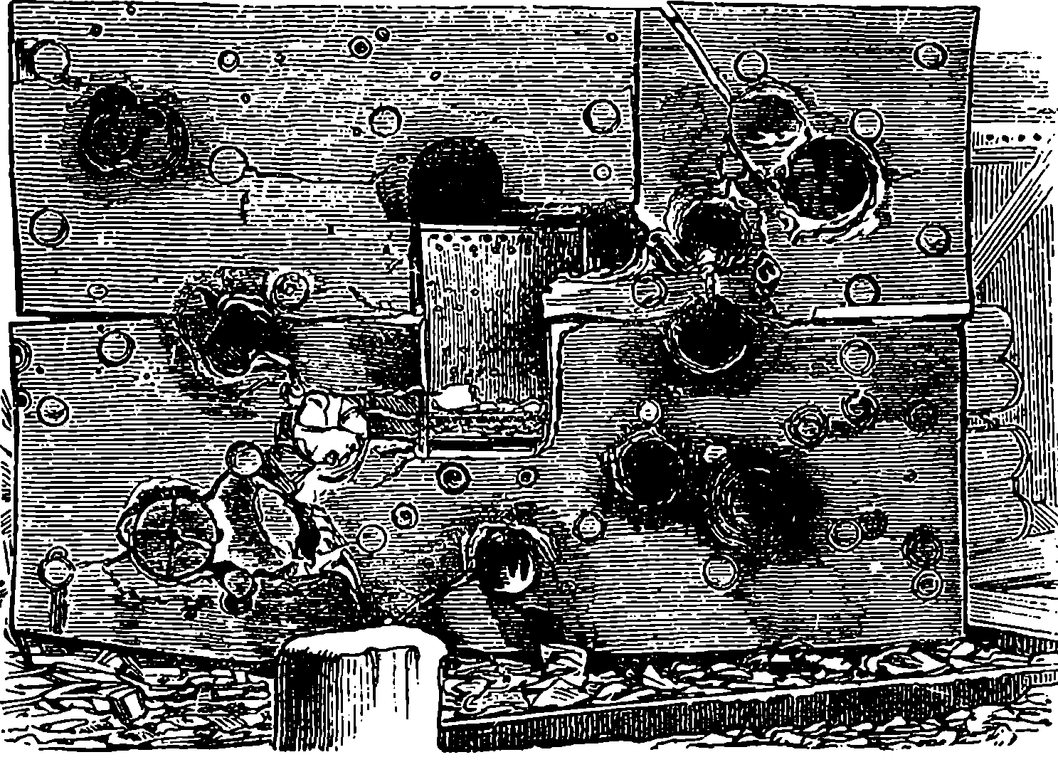
Fig. 95.—Millwall Shield after being battered with Heavy Shot.—Front View.
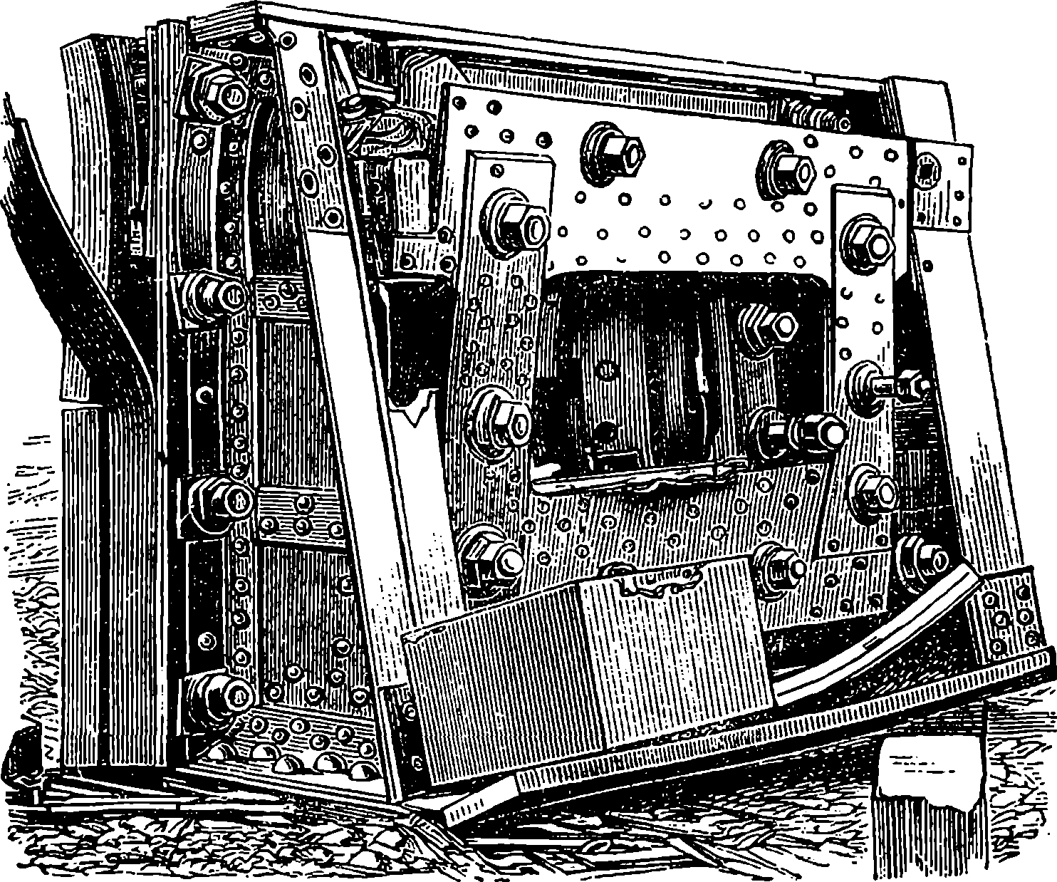
Fig. 96.—Rear View of the Millwall Shield.
Shells are also used with the Woolwich rifled guns. The shells are of the same shape as the solid shots, from which they differ in being cast hollow, and having their interior filled with gunpowder. Such shells when used against iron structures require no fuse; they explode in coming into collision with their object. In other cases, however, the shells are provided with fuses, which cause the explosion when the shot strikes. Fig. 93, page 195, represents one of the 35–ton guns, made on the plan introduced by Mr. Fraser. This piece of ordnance is 16 ft. long, 4 ft. 3 in. in diameter at the breech, and 1 ft. 9 in. at the muzzle. The bore is about 1 ft. Each 200gun can throw a shot or bolt 700 lbs. in weight, with a charge of 120 lbs. of powder. It is stated that the shot, if fired at a short range, would penetrate a plate of iron 14 in. thick, and that at a distance of 2,000 yards it would retain sufficient energy to go through a plate 12 in. thick. The effect of these ponderous missiles upon thick iron plates is very remarkable. Targets or shields have been constructed with plates and timber backing, girders, &c., put together in the strongest possible manner, in order to test the resisting power of the armour plating and other constructions of our ironclad ships. The above two cuts, Figs. 95 and 96, are representations of the appearance of the front and back of a very strong shield of this description, after having been struck with a few 600 lb. shots fired from the 25–ton gun. The shots with chilled heads, already referred to, sometimes 201were found to penetrate completely through the 8 in. front plate, and the 6 in. of solid teak, and the 6 in. of plating at the back. The shield, though strongly constructed with massive plates of iron, only served to prove the relative superiority of the artillery of that day, which was at the time when our century had yet about thirty years to run. Up to 1876 no confidence was placed in steel as a resisting material, a circumstance perhaps not much to be wondered at, as its capabilities had not then been developed by the newer processes of manufacture, described in our article on Iron; nor had mechanicians acquired the power of operating with large masses of the metal. Since then it has come about that only steel is relied upon for efficiently resisting the penetration of projectiles, iron being held of no account except as a backing. There has always been a rivalry between the artillerist and the naval constructor, and this contest between the attacking and the defending agencies is well illustrated in the table on page 166, where the parallel advance in the destructive power of guns and in the resisting power of our war-ships is exhibited in a numerical form.
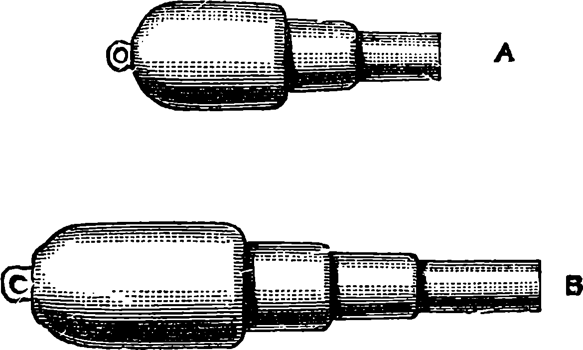
Fig. 97.—Comparative Sizes of 35 and 81 ton Guns. A, 35–ton; B, 81–ton.
The 35–ton Fraser guns were at the time of their production humorously called in the newspapers “Woolwich infants”; but it was not long before they might in another sense be called infants in comparison with a still larger gun of 81 tons weight constructed at Woolwich shortly before iron-coiling and muzzle-loading were set aside. Fig. 97 shows the relative dimensions of the 35–ton and 81–ton guns: the latter was built up in the same way as the 9–inch gun described above, but the coils were necessarily longer and the chase was formed in three parts instead of two. The total length of this gun was 27 feet, and the bore was about 24 feet long and 14 in. in diameter, and the weight of the shot about 1000 lbs., with sufficient energy to penetrate at a considerable distance an iron plate 20 in. in thickness. It was for the manufacture of these very large guns that the great steam hammer, represented in Plate III., was erected at Woolwich.
The 81–ton gun was the largest muzzle-loader ever made in the national gun factory at the time when such huge weapons were in request; but in 1876 its dimensions were surpassed by those of a few 100–ton guns built at Elswick to the order of the Italian Government for 202mounting on their most formidable ironclads. These guns have a calibre of 17·72 inches, and are provided with a chamber of somewhat larger bore to receive the charge of powder. They are built up on the Armstrong shrinkage principle, and comprise as many as twenty different tubes, jackets, hoops, screws, etc., and are undoubtedly the most powerful muzzle-loading weapons ever constructed. It happened, just as these guns were completed, that the British Government, apprehensive at the time of a war with Russia, exercised its rights of purchasing two of them, one to be mounted at Gibraltar, the other at Malta.
The Elswick establishment soon afterwards surpassed all its former achievements in building great guns, by designing and constructing the huge breech-loaders, one of which forms the subject of our Plate XII. These are known as the Armstrong 110–ton guns; they are formed of solid steel throughout, and their weight is accurately 247,795 lbs., or 110 tons 12 cwts. 51 lbs. The total length of the gun is 43 ft. 8 in., and of this 40 ft. 7 in. is occupied by the bore, along which the rifling extends 33 ft. 1 in. The calibre of the rifled part is 16¼ in., and the diameter of the powder chamber is somewhat greater. The regulation charge of powder weighs 960 lbs., although the guns are tested with still greater charges. The weight of the projectile is 1,800 lbs., and it leaves the muzzle with a velocity of 2,128 ft. per second, which is equivalent to a dynamical energy of 56,520 foot-tons. What this means will perhaps be better understood, not by describing experiments such as those on the Millwall Shield, the results of which are depicted in Figs. 95 and 96, but by stating that if the shot from the 110–ton gun encountered a solid wall of wrought iron a yard thick, it would pass through it. The Elswick 110–ton gun is, in fact, the most powerful piece of ordnance that has ever been constructed. There are no trunnions to these great guns, but they are encircled by massive rings of metal, between which pass strong steel bands that tie the gun to its carriage, or, rather, to the heavy steel frame on which it is mounted, and which slides on a couple of girders. The force of the recoil acts on a hydraulic ram that passes through the lower part of the supporting frame. The whole working of the gun is done by hydraulic power, and, indeed, the same method has been applied by the Elswick firm to the handling of all heavy guns. By hydraulic power, maintained automatically by a pumping engine exercising a pressure of from 800 lbs. to 1,000 lbs. per square inch, are operated the whole of the movements required for bringing the cartridge and the projectile from the magazine; for unscrewing the breech block, withdrawing it, and moving it aside; for pushing home the shot and the cartridge to their places in the bore; for closing the breech and screwing up the block; for rotating the turret within which the gun is mounted, or in other cases for ramming the piece in or out, and for elevating or depressing it. It is, indeed, obvious that such ponderous masses of metal as form the barrels and projectiles of these 110–ton and other guns of the larger sizes could not be handled to advantage by any of the ordinary mechanical appliances. But by the application of the hydraulic principle, a very few men are able to work the largest guns with the greatest ease, for their personal labour is thus reduced to the mere manipulation of levers. On board ship the power required for working large guns has lately been sometimes supplied by a system of shafting driven by a steam engine and provided with drums and pulleys, exactly as in an engineer’s workshop. Great care has also been bestowed upon the mounting of the smaller guns, which are so nicely 203poised on their bearings and provided with such accurately fitted racks, pinions, etc., that a steel gun of 10 ft. in length can easily be pointed in any direction by the touch of a child’s hand. The mechanical arrangements are now so admirably adapted for facility of working that, unless in the rude shocks of actual warfare the nicely adjusted machinery is found to be liable to be thrown out of gear, these applications of the engineer’s skill may be considered as having done all that was required to bring our modern weapons to perfection.
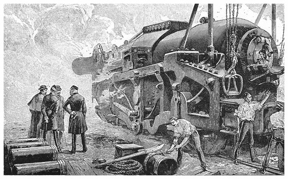
PLATE XII. THE 110–TON ARMSTRONG GUN.
With the construction of the 110–ton we arrive at a period when commences a new era in guns—and especially in the armament of war-ships—necessitated by various circumstances, amongst which may be named the invention of torpedoes and the building of swiftly moving torpedo-boats, and of still swifter “torpedo-boat catchers or destroyers”; so that guns that could be worked only at comparatively long intervals were at a great disadvantage. Again, about 1880, were published the records of a most elaborate and important series of researches conducted by Captain Noble and Sir F. Abel, the chemist of our War Department. They had investigated all the conditions attending the combustion of gunpowder in confined spaces, the nature and quantities of the products, the temperature and pressures of the confined gases, etc. The information thus afforded was extremely valuable; but besides this, direct experiments made with actual guns were carried out, more particularly at Elswick, in which the speed of the projectiles at every few inches of their travel along the bore of the piece was ascertained, and also the pressures of the powder gases at any point. The way in which this is done we shall explain on another page. (See article on Recording Instruments.)
So long as muzzle-loading was in use, guns were necessarily made short, for had they not to be run in from the port-holes and embrasures of forts in order to be loaded? Now there was an obvious disadvantage in this, for the projectile left the gun before the expansive force of the gases had been spent that could have imparted additional velocity. When however muzzle-loading was abandoned, and especially when strong and trustworthy steel became available for the construction of the gun throughout, there was no reason to waste in this way the power of the charge, so that barrels were made lighter, much longer in proportion to the calibre, and every part accurately adapted in strength to the strain to be resisted. For instances of increasing length, take the 38–ton 12–inch guns built up at Woolwich (of only seven pieces) for H.M.S. Thunderer (see Fig. 93), on Mr. Fraser’s plan. These had a bore equal to only 16 times their calibre, while in the Armstrong 100–ton guns the bore is 21 calibres long; and in the 110–ton guns the total length of the chase is 31 times the diameter of the rifled part. It has since been the practice to make the bore of guns from 30 to 40 calibres in length.
The effect of a longer chase used with an appropriate charge is very clearly and instructively shown by the diagram Fig. 98, which is by permission copied from the very comprehensive work by Messrs. E. W. Lloyd and A. G. Hadcock, entitled Artillery: its Progress and Present Position. The reader should not pass over this diagram until he has thoroughly understood it, for it is an excellent example of the graphic method of presenting the results of scientific investigations. At the lower part of the diagram there are drawn to scale half-sections of a long and of a short gun. The horizontal line above is marked in equal parts representing feet numbered from the base of the projectiles. The upright 204line on the left numbered at every fourth division is the scale for the pressures in tons per square inch on the base of the projectile, and these are represented by the height of the plain curves above the horizontal line at each point in the travel of the shot. The dotted lines represent in the same way, but not on the same scale as the former, the velocity with which the base of the projectile passes every point in the chase. The figures 2, 4, and 6 on the upright line at the right-hand side refer only to pressures: the velocities scale is such that the point where the dotted meets the right-hand one is 2,680 units above the horizontal line, as the middle upright in the same way is 1,561 high, and the heights of the dotted lines represent each on the same scale the velocities of the bases of the projectiles at the corresponding parts of the chases. The shorter gun has the rifled part of the chase 15·4 calibres long; the corresponding part of the longer is nearly 33 calibres. The short 7–inch gun has a charge of 30 lbs. of gunpowder, and its projectile weighed 115 lbs. The longer 6–inch gun was not charged with gunpowder, but with the more powerful modern explosive cordite (see Index), of which there was 19·5 lbs., and its projectile weighed 100 lbs. The charges were so adjusted that the shots had the same initial maximum pressure of 20 tons per square inch applied to them. Now the cordite, though much more powerful than gunpowder (that is, a given weight will produce far more gas), is slower in its ignition, continuing longer to supply gas. The maximum pressure, 20 tons in both cases, is suddenly attained by the gunpowder gases, when the shot has hardly moved 6 inches onward, and the pressure declines rapidly as the moving shot leaves more space for the gas; while the cordite gases produce their greatest pressure more gradually at a part where the shot is already about 20 inches on its way, and not only do their highest pressures continue for a greater distance,—but the decline is far less rapid than in the other case. It will be observed by the intersection of the dotted lines, that when the shots in each case have moved about 2 ft. their velocities are equal. They finally leave the muzzles with the velocities marked on the diagram, and if the reader will apply the formula given on page 174 he will obtain their respective energies in foot-lbs.; but for large amounts like these it is more usual to state the energy in foot-tons, which of course will be arrived at by dividing the foot-lbs. numbers by 2,240, and these will work out in the one case to 4978·9 ft.-tons, and in the other to 1942·5 ft.-tons. The shot from the long gun will therefore have more than 2½ times the destructive power of the other.
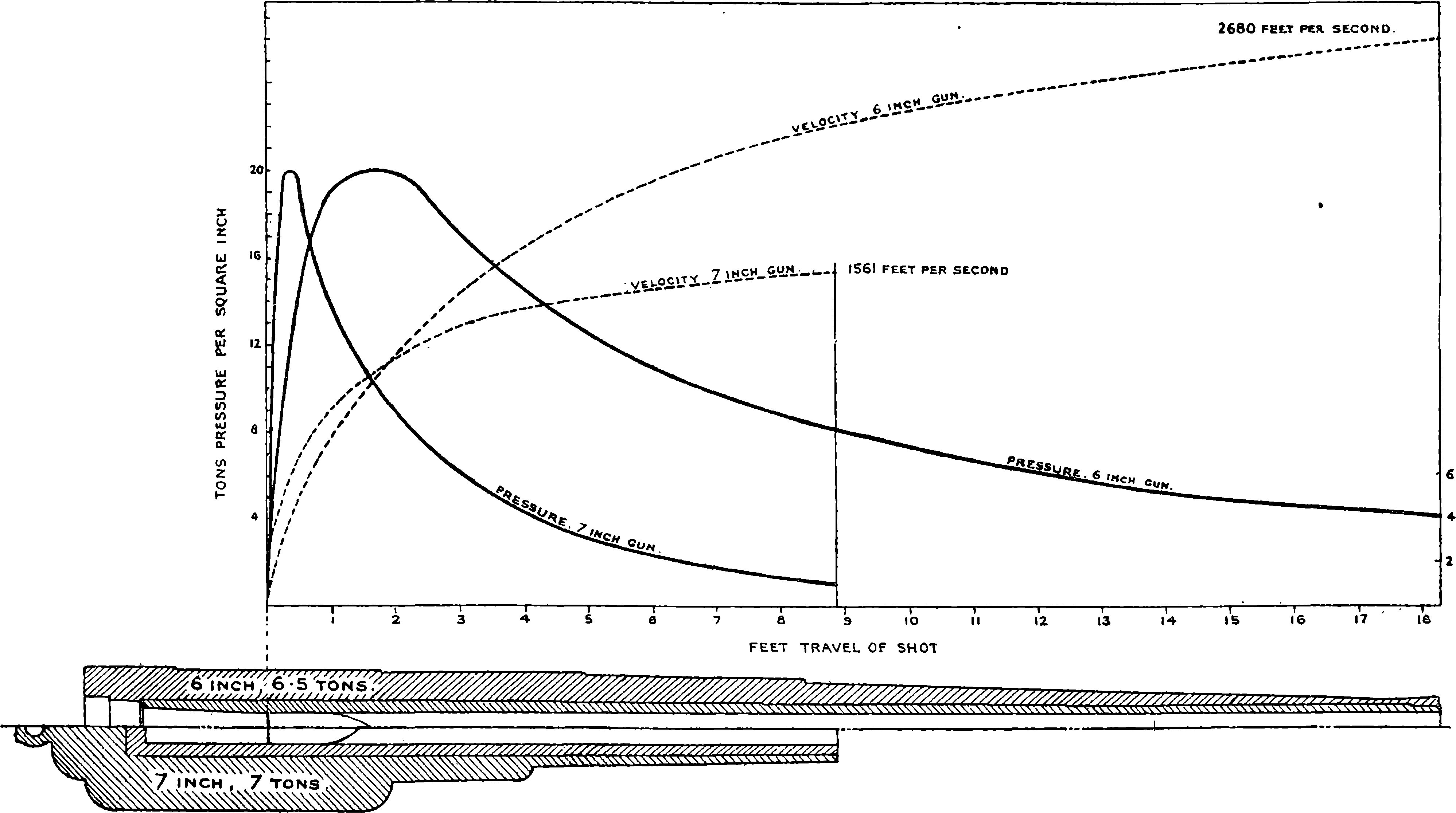
Fig. 98.—Diagram of Velocities and Pressure.
The operations required in constructing guns are multiform, and have to be very carefully conducted so that the workmanship shall be of the best quality. The finest ores are selected for reduction, and the steel is obtained by the Siemens-Martin process already described. It must be free from sulphur and phosphorus, and contain such proportions of carbon, silicon, and manganese as experience has shown to be best, and its composition is ascertained by careful chemical analysis before it is used. The fluid steel is run into large ladles lined with fire-brick, and provided with an opening in the bottom from which the metal can be allowed to run out into the ingot moulds, the size and proportions of these being in accordance with the object required; some admitting of as much as 80 tons at one operation. When a barrel or hoop is required of not less than 6 inches internal diameter the ingot is cut to the required length and roughly bored. The ingot is then heated, a long cylindrical steel bar 206is put through the hole, and under a hydraulic press the hot metal is squeezed into greater length and less diameter. The hole first bored through the ingot is of somewhat greater, and the steel bar (called a mandril) of less, diameter than required in the finished piece. Portions are cut from each end of what is now called the forging and subjected to mechanical tests: if these are satisfactory, the forging is rough bored and turned on the outside. It is then annealed, by being heated and allowed to cool very slowly. The next operation is to harden the metal by raising it to a certain temperature, at which it is immersed in rape oil until cold. Then the piece is again annealed, and fine-turned and bored. All these operations have to be performed not only on the barrel, but also on each hoop, before the hoops are shrunk on, and the greatest nicety of measurement is required in each piece. Then the gun has to be turned on the outside, the screw for the breech piece cut, the bore rifled, etc. The object of the annealing is to relieve the metal from internal strains. It will not be wondered at that months are required for the construction of the larger kind of guns. Thus at Elswick a 6 in. quick firing gun, upon which men are employed night and day, cannot be completed in less than five months, and sixteen months are required for making a 67–ton gun.
We may take as an illustration of the progress of modern artillery one of the products of the Elswick factory which has just been referred to, and for which the demand from all quarters has been unprecedentedly great, namely, the 4·7 inch gun. This weapon is mounted in various manners according to the position it has to occupy, whether for a land defence, or on ship-board between decks, or on the upper deck. The arrangement shown in Fig. 99, which is reproduced from Messrs. Lloyd & Hadcock’s work, is known as the centre pivot mounting, and is suitable for such a position as the upper deck of a ship. The reader should compare the proportions and mounting of this weapon with those of the old 32–pounder sketched in Fig. 90, observing the very much greater comparative length of the modern weapon, and the mechanism for elevating and training it (which, however, the scale of the drawing crowds into too small a space to show as it deserves). C is a projection from the breech, to which is attached the piston of the recoil press; at T is the handle for training, which actuates a worm at V; the elevation is regulated by the turning of the four-armed wheel. The long chase of the gun projects in front; but the mounting and the breech machinery are protected by shields of thick steel, of which the sections of two plates are denoted by the dark upright parts in front. These are fixed; but a movable plate above the gun can be raised or lowered into an inclined position, for better taking sights. In the figure this is shown as open and in a horizontal position. This gun is provided with sights by which it can be aimed at night; that is, the sights can be illuminated by small electric lamps suitably placed; the wires connecting these with voltaic battery cells carried on the mounting are indicated. The figure represents the gun as constructed about 1893, but the improvements that are continually being made have brought about some modifications in the details.
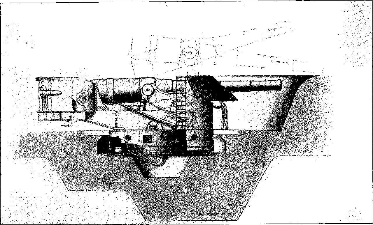
Fig. 99.—Elswick 4·7 inch Q. F. Gun on Pivot Mounting.
Very notable among the productions of the great Elswick factory are the quick firing guns. These were at first confined to guns of small calibre, such as the 6–pounders. They are, of course, all breech-loaders, and the powder and shot are both contained in a single metallic cartridge 208case. A more formidable weapon of the same class is the 45–pounder rapid firing gun, which, like the rest, is constructed entirely of steel, with a total length of 16 ft. 2½ in., a calibre of 4·724 in., and a length of bore equal to 40 diameters. The weight of this gun is 41 cwt., and it throws a shell of 45 lbs. weight with a 12–lb. charge of gunpowder. Quick firing guns having a calibre of 6 in. are now also made in great numbers for arming our ironclads. The breech block in the quick firing guns turns aside on a hinge, and after the introduction of the cartridge it is closed and screwed up to its place by a slight turn of a handle. The piece is then pointed and trained by aid of mechanical gearing as in the case of the heavier guns. But Mr. Hotchkiss has introduced a simpler method of elevating and training his 3–pounder and 6–pounder quick firing guns, by attaching to the rear, and unaffected by the recoil, a shoulder piece against which the marksman can lean, and move the weapon as he takes his aim. Though these guns weigh respectively 4½ cwt. and 7 cwt., they can thus be pointed with the greatest ease. The firing is done by pulling a trigger in what seems like the stock of a pistol. The empty cartridge case is automatically extracted from the firing chamber by the act of opening the breech, and it drops to the ground. Ten or twelve rounds per minute can be fired from these guns, and Lord Armstrong has advocated the use of a number of them for naval armament in preference to that of a few ordinary breech-loaders of more unwieldy dimensions. He has calculated that in a given time a far greater weight of metal can be projected from a vessel armed with quick firing guns than from one provided only with the heavier class of cannons.
The breech pieces in the Elswick guns are closed on the “interrupted screw” system—that is, a very large screw thread of V-shaped section is cut in the barrel at the breech end, and a corresponding thread on the principal part of the breech block, which is, of course, capable of rotating about the axis. The screw threads, however, are not continuous, segments parallel to the axis being cut away, the spaces in the outer thread corresponding with the projecting parts in the inner, and vice versâ, so that when the block is pushed home, one very small part of a turn suffices to engage all the threads. The screw is also made conical, and is so cut into steps, as it were, that great resisting power is brought into play. The Elswick guns are provided with hydraulic buffers for checking the recoil, and the principle is applied in various modified forms. In some cases the pistons allow for the water a passage, which towards the end gradually diminishes. This is the arrangement for the 3–pounder rapid firing Hotchkiss gun, and the force of the recoil is made at the same time to compress two springs, which serve to return the gun to the firing position. This very handy gun is said to be able to fire twenty rounds per minute. In Mr. Vavasseur’s plan of mounting, the recoil is checked by ports, or openings, in the piston of a hydraulic cylinder being gradually closed, which is easily arranged by making a spiral groove within the cylinder, which gives a small axial motion to part of the piston.
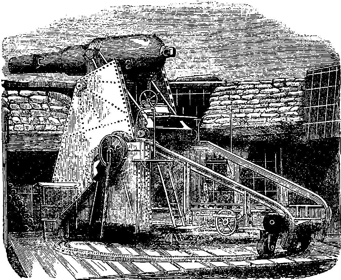
Fig. 100.—The Moncrieff Gun raised and ready for firing.
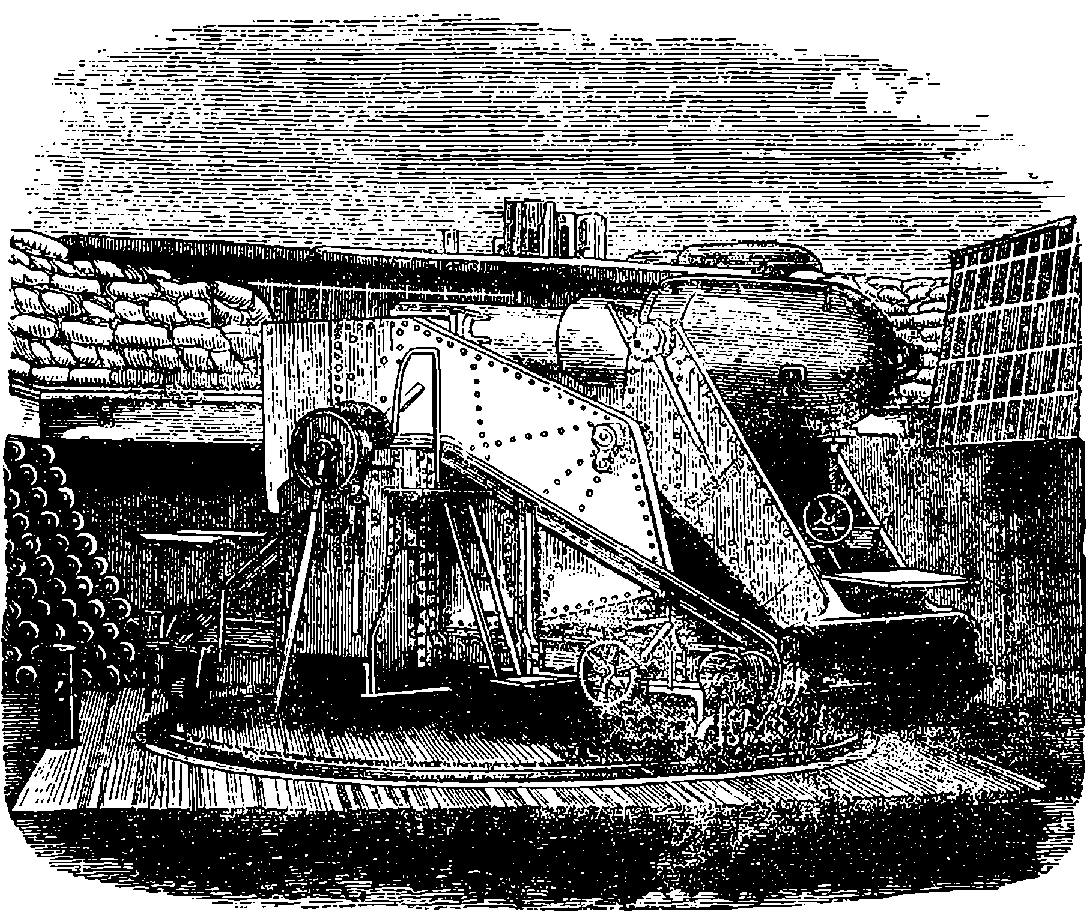
Fig. 101.—Moncrieff Gun lowered for loading.
An extremely effective plan for the defence of coasts and harbours was originated by Colonel Moncrieff, when about 1863 he contrived a method of mounting large guns on the disappearing system, by which almost complete protection against hostile fire is given to both gun and gunners. He utilizes the recoil as a means of bringing the gun down into a protected position the moment it has been fired, and retains this energy by a simple arrangement until the piece has been reloaded, when it is 209allowed to expend itself by again raising the gun above the parapet into the original firing position. The configuration and action of Colonel Moncrieff’s gun-carriage will be understood by an inspection of the annexed illustrations, where in Fig. 100 is shown the gun raised above 210the parapet and ready for firing. When the discharge takes place, the gun, if free, would move backwards with a certain speed, but the disposition of the mounting is such that this initial velocity receives no sudden check, the force being expended in raising a heavy counterpoise, and at the same time the gun is permitted to descend, while maintaining a direction parallel to its firing position. At the end of the descent, which, it must be understood, is caused by the force of the recoil, and not by the counterpoise, for this more than balances the weight of the gun, the latter is retained as shown in Fig. 101 until it has been reloaded; and when it has again to be fired, it is released so as to allow the descent of the counterpoise to raise it once more into position. The great advantage of this invention is the protection afforded to the artillerymen and gun while loading; and even the aiming can be accomplished by mirrors, so that the men are exposed to no danger, except from “vertical fire,” which involves but little risk.
Colonel Moncrieff took out a patent for his invention in 1864, but committed the practical working out of his idea to the firm of Sir W. G. Armstrong & Co., in whose hands the design was ultimately transformed from the original somewhat cumbersome arrangement of the mounting into the compact and manageable form shown in Fig. 102, which represents a 13·9 inch 68–ton breech-loading disappearing gun on the Elswick hydro-pneumatic mounting. The principle of hydraulic power is fully explained in our article on that subject, and an example of its application to cranes as devised by Sir W. Armstrong is there described. When guns began to be made very large, and projectiles weighing several cwts. had to be dealt with, the application of power in some form became essential for loading, running out, elevating, training, etc.; and though steam-power naturally was first used, hydraulic power was adopted at Elswick, and has been there applied to the mountings of large guns with the greatest success by Mr. G. W. Rendel. To mention the various arrangements in which this power is applied, or to attempt any description of the elaborate machinery by which it is regulated, would carry us far beyond our limits. But the powerful weapon depicted in Fig. 102 is designed to be worked only by the manual effort of a few men. In this mounting the pressure of condensed air sustains the gun in the firing position; that pressure, acting upon the water in the recoil presses, having previously forced up their rams so as to turn into a nearly vertical position the strong brackets or beams on which the trunnions are supported. The recoil is checked in the usual way by the forcing of the water through small ports or valves as the ram descends, but these valves are so arranged that the water is in part forced back into the air chamber, and there recompresses the air, to restore the power for again raising the gun. The pressure in the air chamber when the gun is down may be about 1,400 lbs. per square inch; when it is up this will be reduced to perhaps one half by the expansion of the air in doing work. We have here the reaction of compressed air taking the place of the gravity of the counterpoise originally designed. There are in this hydro-pneumatic mounting a number of adjusting appliances, such as forcing pumps, brakes, etc., for regulating the pressures, or quantity of liquid, as, for instance, when lowering the gun without any recoil action in operation. Then again, with any change in the weight of projectile or in the powder charge, there would be a corresponding change in the power of the recoil, and therefore the necessity for compensatory adjustments, which are made 212with great readiness. The nicety with which the parts are adapted to each other in this mounting must be obvious, when we observe the magnitude of the mass to be moved with the least delay, and brought to rest, quite gently and exactly, in a new position. Details cannot here be given even of the method by which the valves in the recoil cylinders are automatically controlled for this purpose. Means are also supplied for setting the gun, while still in its protected position, to the required angle of elevation or depression. The adjustment is made by the long rods attached near the breech and set at their lower ends to the position giving the intended angle to the raised gun. The varied and powerful strains to which the parts of this mechanism are subject, and which have had to be calculated and provided for, may be inferred from the enormous recoil energy of the gun, which under ordinary conditions amounts to no less than 730 foot-tons. The gun is provided with ordinary, and also with reflecting, sights, so that no one need be exposed to the enemy’s fire. Protective armour above the gun is not required, as the pit itself being usually on some elevation is imperceptible to the enemy, and the gun is visible but for a few seconds, forming a quite inconspicuous object. The pit in which the gun is mounted is commonly lined with concrete. Italy, England, Norway, Japan and other countries have appreciated the advantages of the disappearing system in providing the most powerful coast defences yet devised, and a great many guns have been mounted on this principle.
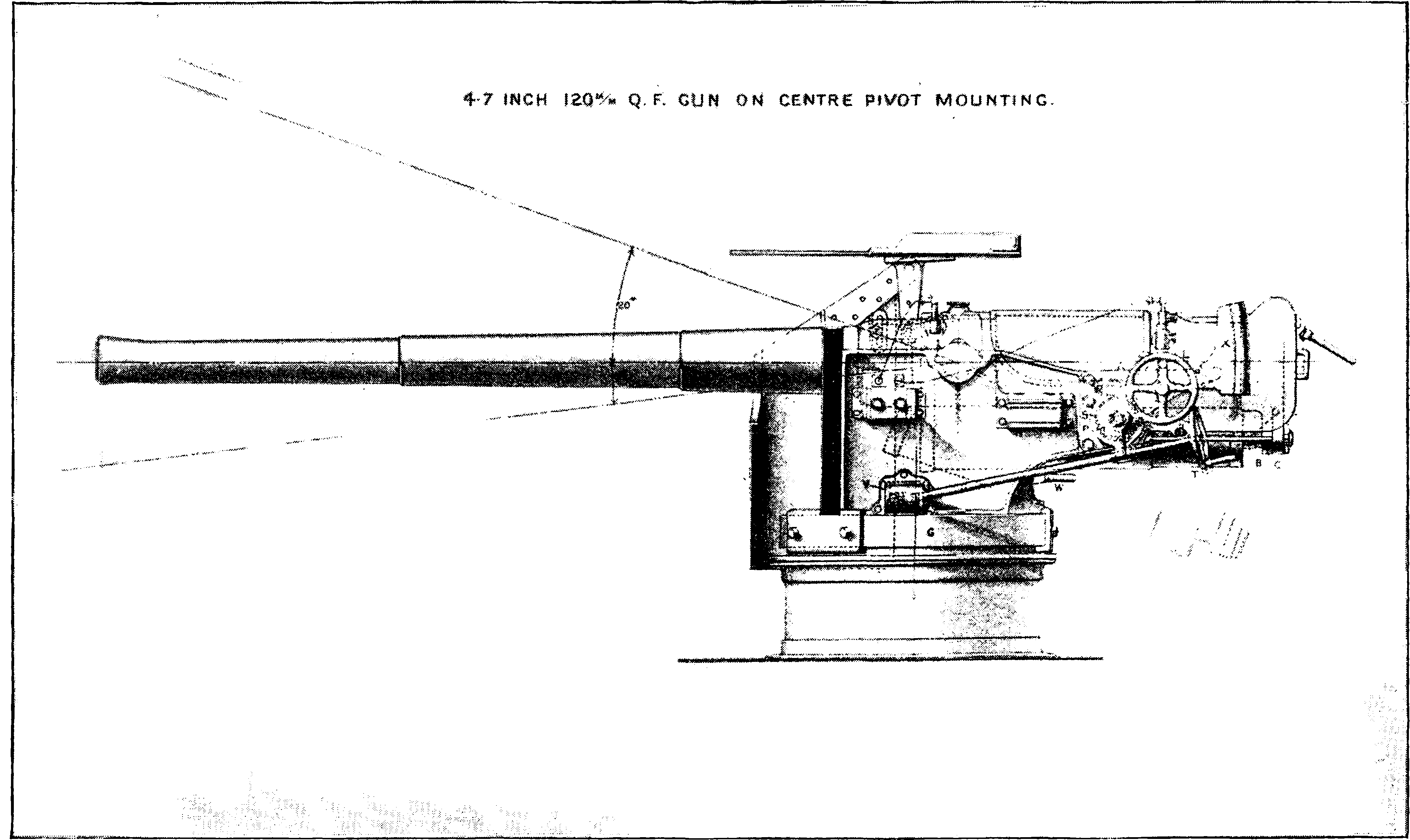
Fig. 102.—68–ton Gun on Elswick Hydro-Pneumatic Mounting.
An extraordinary piece of ordnance is represented in Fig. 103. It is one of two huge mortars, the idea of which presented itself to Mr. Mallet during the Crimean War, the intention being to throw into the Russian lines spherical shells a yard in diameter, which would, in fact, have constituted powerful mines, rendering it impossible for the fortifications to continue tenable. Mallet’s original design was to project these shells from mortars of no less than 40 tons weight. When it was pointed out that the transport of so heavy a mass would be impracticable, the design was changed to admit of the mortar being made in pieces not exceeding eleven tons in weight, and built up where required. During the most active period in the siege of Sebastopol this plan was submitted to Lord Palmerston, who at once ordered two of these apparently formidable pieces to be constructed, without waiting for official examinations of the scheme, and the usual reports of experts,—promptness in this case being considered of the utmost importance. A contract was made with a private firm, who undertook to deliver them in ten weeks. But the difficulties attending such constructions not being understood at the time, delays arose, the contractors failed, and two years elapsed before the mortars were completed. In the meantime peace had been concluded, and the mortars were never fired against any hostile works; but experiments were made with one of them at Woolwich. The heaviest of the shells it was intended to project weighed 2,940 lbs., and for this it was proposed to use a charge of 80 lbs. of gunpowder. In the experiments the charges first used were low, but gradually increased: when it was found that after every few rounds repairs became necessary in consequence of the weak points in the construction, and after the nineteenth round the mortar was so much damaged that the trials were definitely discontinued. The other mortar, though mounted, was never fired, but remains at Woolwich, an object of some interest to artillerists, especially since there has been some talk of reverting to this very old-fashioned form of 213ordnance as a means of attacking ironclads in their most vulnerable direction by the so-called vertical fire. In one of the rounds of the Mallet mortar tried at Woolwich, a shell weighing 2,400 lbs. was thrown by a charge of 70 lbs. of gunpowder a distance of more than a mile and a half, and it buried itself in the soil to a very great depth.
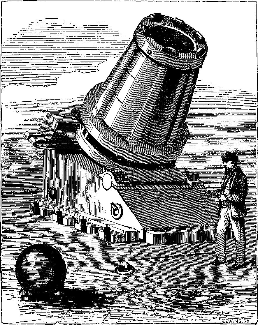
Fig. 103.—Mallet’s Mortar
For high-elevation firing, howitzers will more probably be the form of ordnance most in use. The range of the howitzer is determined by the angle at which it is elevated, whereas with the mortar it is chiefly by variation of the powder charge that the aim is adjusted. Many of the old short 9 in. muzzle-loaders have already been converted into 11 in. 214rifled howitzers, and these are likely to prove of great service in defending our harbours and channels against war vessels.
Some account has been given in a preceding article of the great steel works of Krupp & Co. at Essen, and the place has been noted as one of the greatest gun factories in the world during the second half of our century. The process there practised of casting crucible steel ingots, and already described, is precisely that used in the first stage of gun-making. The steel for guns put into the crucibles is a carefully adjusted mixture of one quality of iron puddled into steel and subjected to certain treatment; the other portion is made from a different quality of iron from which all the carbon has been puddled out. The cast ingot is forged under a great steam hammer, bored, turned, and steel hoops shrunk upon it, in several layers, and other operations are performed upon it like those which have already been mentioned. A 14 in. gun is said to require sixteen months for its manufacture, and its cost to be about £20,000.
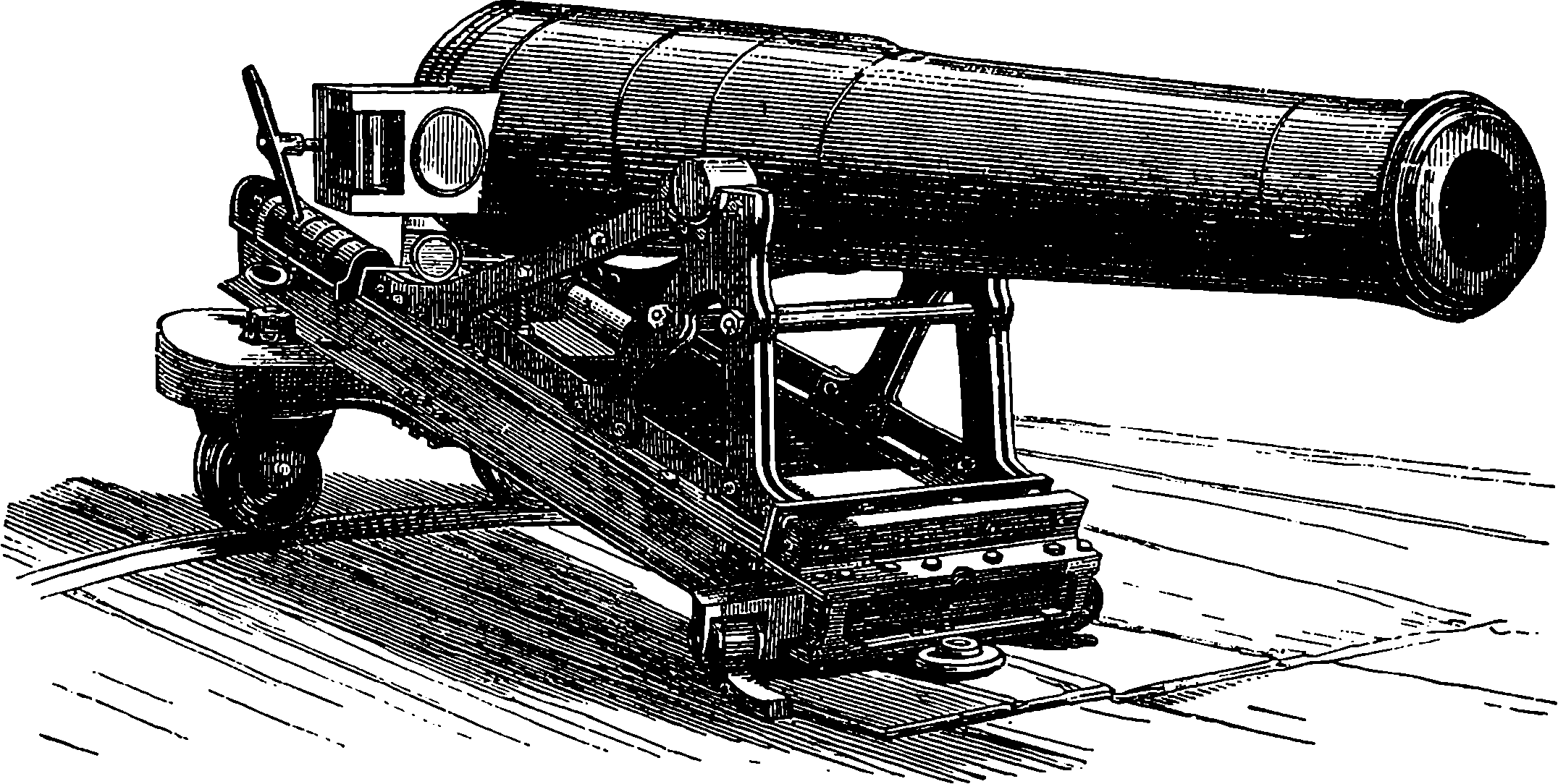
Fig. 104.—32–pounder Krupp Siege Gun, with Breech-piece open.
Artillerists had long carried on a warm controversy as to the relative merits of wrought iron and steel in gun construction, the latter material being regarded with shyness on account of its want of uniformity as formerly produced. Krupp however began as early as 1847 to make guns of his excellent crucible steel, and through bad report and good report confined himself to this material until, it is asserted, by 1878 he had supplied over 17,000 steel guns of all calibres. He began by making a 3–pounder gun, but soon produced pieces of larger size, all of which were bored and turned out of solid masses of metal. At a later period the plan of shrinking on strengthening hoops of steel was adopted. The Krupp guns have found extensive favour, and many very heavy ones have been made, some indeed of greater weight than the 110–ton Armstrong; but the excess of weight is due to the mass of metal which the Krupp construction of the breech mechanism requires. Thus Krupp’s 120–ton gun has a muzzle energy of but 45,796 foot-tons, while that of the Elswick piece is 55,105 foot-tons.
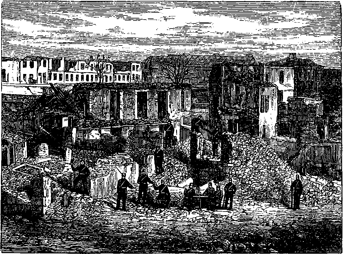
Fig. 105.—The Citadel of Strasburg after the Prussian Bombardment.
The breech arrangement in the Krupp guns consists of a lateral slot into which slides a closing block after the charge has been inserted from the rear. An obsolete form of this breech piece is seen in Fig. 104, which 215represents a 32–pounder gun such as was used in sieges by the Prussians in the Franco-German War. It will be observed here that the slot and breech piece are of rectangular form; but this shape, causing the piece to be weak where most strength was required, was afterwards altered into a D-shaped section, the curved side being of course to the rear. That difficulty which baffled the earliest attempts at breech-loading is the same that has given much trouble to modern gunmakers. It consists in so closing the breech that no escape of the powder gases can take place there at the moment of discharge. When we remember that the momentary pressure of the gases in the powder chamber may amount to more than 40 tons on the square inch, we can well understand the enormous velocity with which they will rush forth from even the smallest interspace between the base of the gun and the breech block, but we can hardly realise without actual inspection the mechanical action they produce in their passage: when once the escape occurs, a channel is cut in the metal as if part had been removed by an instrument, and the piece in that condition is disabled for further use. Several devices are in use obtaining perfect closure of the breech, which is technically called obturation (Latin, obturare, to close up). One of these consists in fitting closely into the circumference of the bore a ring of very elastic steel, turned up at the edges towards the powder chamber. The gas pressure forces the edge of this ring still more closely against the interior of the powder chamber, much in the same way as the Bramah collar acts in the hydraulic press (see Fig. 165). The shaded circle shown on the breech piece in Fig. 104 is an additional device for obtaining obturation. The Broadwell 216ring, as the above-mentioned contrivance is called, is not used in English guns, but another plan of obtaining a gas-joint has been much adopted, in which a squeezable pad is by compression forced outwards to close up the bore.
A very long range was claimed for Krupp’s guns at the time of the Franco-German War, for at the siege of Paris (1870) it was said they could hurl projectiles to the distance of five miles, though probably there was some exaggeration in this statement. There is no doubt however that the Prussians had very effective and powerful artillery, as may be gathered from Fig. 105, which is taken from a photograph of part of the fortifications of Strasburg after the bombardment of that fortress. The explosive shells used by the Prussians against masses of troops were not precisely segment shells of the form already described, but the principle and effect were the same, for the interior was built up of circular rings, which broke into many pieces when the shell exploded.
Out of the very numerous forms in which modern ordnance is constructed, we have been able to select but a few examples for illustration and description. These will suffice, it is hoped, to give an idea of the progress that the century has witnessed. It would be beyond our scope to give details of the ingenious mechanical devices that have come to be applied to guns: such as the breech-closing arrangements, the various ways in which recoil is controlled and utilized, etc. A good illustration, had space permitted, of the scientific skill applied to ordnance would be found in the contrivances fitted to certain projectiles in order to determine their explosion at the proper moment. These are very different from the cap or time fuse that did duty in the first half of the century. We have indeed said little of the projectiles themselves beyond mention of the Palliser chilled shot and the obsolete studded projectiles. We have not explained how bands of copper, or other soft metal, are put round a certain part of the shot or shell, in order that, being forced into the grooves, the axial rotation may be imparted, or how windage is prevented by “gas checks” attached to the base of the projectiles. We must now be contented to conclude this section by showing the structure of two kinds of explosive shells which have been much used.
Shrapnel shell takes its name from Lieutenant Shrapnel, who was its inventor about the end of last century, but the projectile began to be used only in 1808. Fig. 105a is a section showing the shell as a case containing a number of spherical bullets, of which in the larger shells there are very many, the interspaces being filled with rosin, poured in when melted; the bullets are thus prevented from moving about. The figure shows the shell without the fuse or percussion apparatus, which screws into the hollow at the front. The bursting charge of gunpowder is behind the bullets, and when it explodes they travel forward with a greater velocity than the shell, but with trajectories more or less radiating, carrying with them wide-spreading destruction and death.
A shrapnel shell may be said to be a short cannon containing its charge of powder in a thick chamber at the breech end; the sides of the fore part of the shell are thinner than those of the chamber, and may be said to form the barrel of the cannon. This cannon is loaded up to the muzzle with round balls, which vary with the shell in size. An iron disc between the powder and the bullets represents the wad used in ordinary fowling-pieces. A false conical head is attached to the shell, so that its outward appearance is very similar to that of an ordinary cylindro-conoidal shell: 217that is to say, it looks like a very large long Enfield bullet. The spinning motion which had been communicated to the shell by the rifling of the gun from which it had been fired causes the barrel filled with bullets to point in the direction of the object at which the gun has been aimed. Consequently, when the shrapnel shell is burst, or rather fired off, the bullets which it contained are streamed forward with actually greater velocity than that at which the shell had been moving; and the effect produced is similar to firing grape and canister from a smooth-bore cannon at a short range.
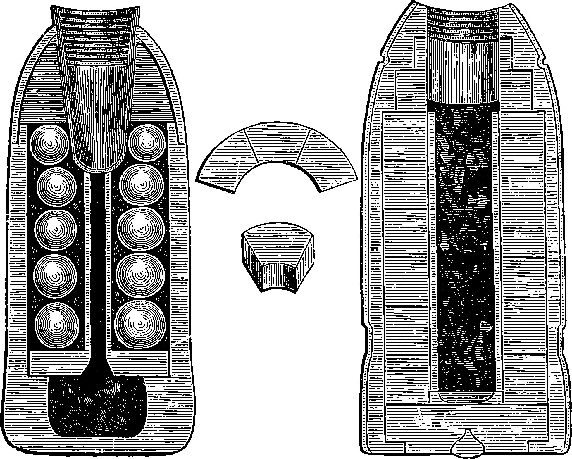
Fig. 105a.—The Shrapnel and Segment Shells.
Segment shells were first brought into use by Lord Armstrong in 1858 in connection with his breech-loading guns. The segment shell consists of a thin casing like a huge conical-headed thimble, with a false bottom attached to it. It is filled with small pieces of iron called “segments,” cast into shapes which enable them to be built up inside the outer casing into two or more concentric circular walls. The internal surface of the inmost wall forms the cavity of the compound or segment shell, and contains the bursting charge. The segment shell is fitted with a percussion fuse, which causes it to explode when it strikes. In the shrapnel shell, the powder charge is situated in rear of the bullets, and consequently produces the chief effect in a forward direction. In the segment shell, the powder is contained inside the segments, and therefore produces the chief effect in a lateral direction. When the shrapnel shell is burst at the right moment, its effect is greatly superior to that of the segment shell; on the other hand, the segment shell, when employed at unknown or varying distances, is far more unlikely to explode at the proper time.
Shrapnel and segment shells can be used with field artillery, i.e., 2189–pounders, 12–pounders, 16–pounders; and also with heavy rifled guns in fortresses, viz., 40–pounders, 64–pounders, 7–in. and 9–in. guns. But the conditions of their service are very different in each case. With regard to field artillery, the distance of the enemy is rarely known, and is constantly changing, and hence the men who have to adjust the fuses would probably be exposed to the fire of the enemy’s artillery, and, consequently, could not be expected to prepare the fuses with the great care and nicety which are absolutely necessary to give due effect to the shells. There are, however, some occasions when the above objections would not hold good—as, for instance, when field artillery occupy a position in which they wait the attack of an enemy advancing over ground in which the distances are known.
Segment shells require no adjustment of their percussion fuse. They enable the artillerymen to hit off the proper range very quickly, since the smoke of the shell which bursts on striking tells them at once whether they are aiming too high or too low.
With regard, however, to the service of heavy rifled guns in fortresses, the conditions are quite different. In the first place, the distance of all objects in sight would be well known beforehand; and in the second place, the fuses of the shells would be carefully cut to the required length in the bomb-proofs, where the men would be completely sheltered. The 7–in. shrapnel contains 227 bullets, and a 9–in. shrapnel would contain 500 bullets of the same size, and these shells could be burst with extraordinary accuracy upon objects 5,000, 6,000, or 7,000 yards off.
MACHINE GUNS.
The name of machine guns has been applied to arms which may be regarded as in some respects intermediate between cannons and rifles, since in certain particulars they partake of the nature of both. Like the former, they are fired from a stand or carriage, and in some of their forms require more than one man for their working: in the calibre of their barrels and the weight of their projectiles, they are assimilated to the rifle, but they are capable of pouring forth their missiles in a very rapid succession—so rapid indeed as practically to constitute volley firing. The firing mechanism of the machine gun has always an automatic character, but the rifle has acquired this feature, so that it cannot be made a distinguishing mark: on the other hand, since machine guns have been made to discharge projectiles of such weights as 1 lb. or 3 lb. there is nothing to separate them from quick-firing ordnance unless it be the automatic firing.
The idea of combining a number of musket-barrels into one weapon, so that these barrels may be discharged simultaneously or in rapid succession, is not new. Attempts were made two hundred years ago to construct such weapons; but they failed, from the want of good mechanical adjustments of their parts. Nor would the machine gun have become the effective weapon it is, but for the timely invention of the rigid metallic-cased cartridge. Several forms of machine guns have in turn attracted much attention. There is the Mitrailleur (or Mitrailleuse), of which so much was heard at the commencement of the Franco-German War, and of whose deadly powers the French managed to circulate terrible and mysterious reports, while the weapon itself was kept concealed. 219Whether this arose from the great expectations really entertained of the destructive effects of the mitrailleur, or whether the reports were circulated merely to inspire the French troops with confidence, would be difficult to determine. Our own policy in regard to new implements of war is not to attempt to conceal their construction. Experience has shown that no secret of the least value can long be preserved within the walls of an arsenal, although the French certainly apparently succeeded in surrounding their invention with mystery for a while. The machine gun, or “battery,” invented by Mr. Gatling, an American, is said by English artillerists to be free from many defects of the French mitrailleur. In 1870 a committee of English military men was appointed to examine the powers of several forms of mitrailleur, with a view to reporting upon the advisability or otherwise of introducing this arm into the British service. They recommended for certain purposes the Gatling battery gun.
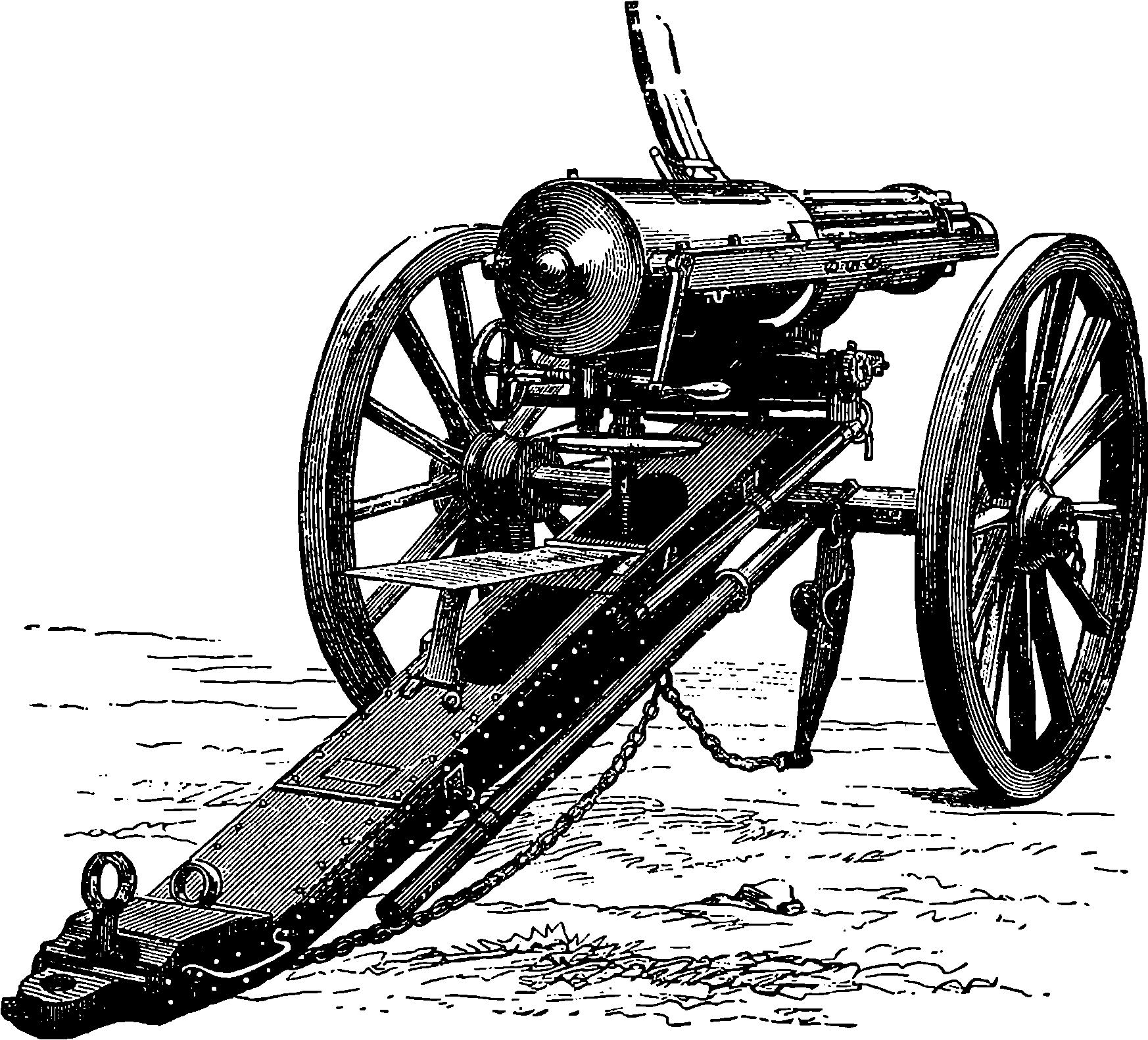
Fig. 105b.—The Gatling Gun.—Rear View.
In the Gatling the barrels, ten in number, are distinct and separate, being screwed into a solid revolving piece towards the breech end, and passing near their muzzles through a plate, by which they are kept parallel to each other. The whole revolves with a shaft, turning in bearings placed front and rear in an oblong fixed frame, and carrying two other pieces, which rotate with it. These are the “carrier” and the lock cylinder. Fig. 105b gives a rear view, and Fig. 105c a side view, of the Gatling battery gun. The weapon is made of three sizes, the largest one firing bullets 1 in. in diameter, weighing ½ lb., the smallest discharging bullets of ·45 in. diameter. The small Gatling is said to be effective at a range of more than a mile and a quarter, and can discharge 400 bullets or more in one minute. Mr. Gatling thus describes his invention:
“The gun consists of a series of barrels in combination with a grooved 220carrier and lock cylinder. All these several parts are rigidly secured upon a main shaft. There are as many grooves in the carrier, and as many holes in the lock cylinder, as there are barrels. Each barrel is furnished with one lock, so that a gun with ten barrels has ten locks. The locks work in the holes formed in the lock cylinder on a line with the axis of the barrels. The lock cylinder, which contains the lock, is surrounded by a casing, which is fastened to a frame, to which trimmers are attached. There is a partition in the casing, through which there is an opening, and into which the main shaft, which carries the lock cylinder, carrier, and barrels, is journaled. The main shaft is also at its front end journaled in the front part of the frame. In front of the partition in the casing is placed a cam, provided with spiral surfaces or inclined planes.
“This cam is rigidly fastened to the casing, and is used to impart a reciprocating motion to the locks when the gun is rotated. There is also in the front part of the casing a cocking ring which surrounds the lock cylinder, is attached to the casing, and has on its rear surface an inclined plane with an abrupt shoulder. This ring and its projection are used for cocking and firing the gun. This ring, the spiral cam, and the locks make up the loading and firing mechanism.
“On the rear end of the main shaft, in rear of the partition in the casing, is located a gear-wheel, which works to a pinion on the crank-shaft. The rear of the casing is closed by the cascable plate. There is hinged to the frame in front of the breech-casing a curved plate, covering partially the grooved carrier, into which is formed a hopper or opening, through which the cartridges are fed to the gun from feed-cases. The frame which supports the gun is mounted upon the carriage used for the transportation of the gun.
“The operation of the gun is very simple. One man places a feed-case filled with cartridges into the hopper; another man turns the crank, which, by the agency of the gearing, revolves the main shaft, carrying with it the lock cylinder, carrier, barrels, and locks. As the gun is rotated, the cartridges, one by one, drop into the grooves of the carrier from the feed-cases, and instantly the lock, by its impingement on the spiral cam surfaces, moves forward to load the cartridge, and when the butt-end of the lock gets on the highest projection of the cam, the charge is fired, through the agency of the cocking device, which at this point liberates the lock, spring, and hammer, and explodes the cartridge. As soon as the charge is fired, the lock, as the gun is revolved, is drawn back by the agency of the spiral surface in the cam acting on a lug of the lock, bringing with it the shell of the cartridge after it has been fired, which is dropped on the ground. Thus, it will be seen, when the gun is rotated, the locks in rapid succession move forward to load and fire, and return to extract the cartridge-shells. In other words, the whole operation of loading, closing the breech, discharging, and expelling the empty cartridge-shells is conducted while the barrels are kept in continuous revolving movement. It must be borne in mind that while the locks revolve with the barrels, they have also, in their line of travel, a spiral reciprocating movement; that is, each lock revolves once and moves forward and back at each revolution of the gun.
“The gun is so novel in its construction and operation that it is almost impossible to describe it minutely without the aid of drawings. Its main features may be summed up thus: 1st.—Each barrel in the gun is provided with its own independent lock or firing mechanism. 2nd.—All the locks revolve simultaneously with the barrels, carrier, and inner breech, when the 221gun is in operation. The locks also have, as stated, a reciprocating motion when the gun is rotated. The gun cannot be fired when either the barrels or locks are at rest.”
There is a beautiful mechanical principle developed in the gun, viz., that while the gun itself is under uniform constant rotary motion, the locks rotate with the barrels and breech, and at the same time have a longitudinal reciprocating motion, performing the consecutive operations of loading, cocking, and firing without any pause whatever in the several and continuous operations.
The small Gatling is supplied with another improvement called the “drum feed.” This case is divided into sixteen sections, each of which contains twenty-five cartridges, and is placed on a vertical axis on the top of the gun. As fast as one section is discharged, it rotates, and brings another section over the feed aperture, until the whole 400 charges are expended.
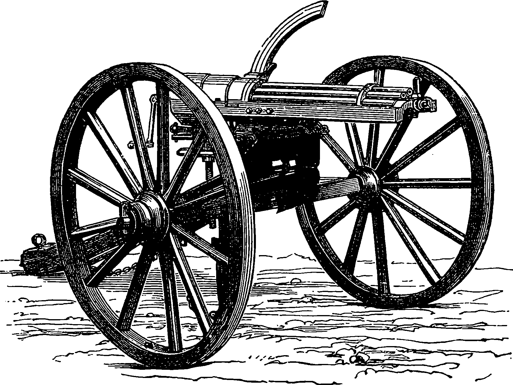
Fig. 105c.—The Gatling Gun.—Front View.
After a careful comparison of the effects of field artillery firing shrapnel, the committee concluded that the Gatling would be more destructive in the open at distances up to 1,200 yards, but that it is not comparable to artillery in effect at greater distances, or where the ground is covered by trees, brushwood, earthworks, &c. The mitrailleur, however, would soon be knocked over by artillery if exposed, and therefore will probably only be employed in situations under shelter from such fire. An English officer, who witnessed the effects of mitrailleur fire at the battle of Beaugency, looks upon the mitrailleur as representing a certain number of infantry, for whom there is not room on the ground, suddenly placed forward at the proper moment at a decisive point to bring a crushing fire upon the enemy. Many other eye-witnesses have spoken of the fearfully deadly effect of the mitrailleur in certain actions during the Franco-German War.
Mr. Gatling contends that, shot for shot, his machine is more accurate than infantry, and certainly the absence of nerves will ensure steadiness; 222while so few men (four) are necessary to work the gun that the exposure of life is less. No re-sighting and re-laying are necessary between each discharge. When the gun is once sighted its carriage does not move, except at the will of the operator; and the gun can be moved laterally when firing is going on, so as to sweep the section of a circle of 12° or more without moving the trail or changing the wheels of the carriage. The smoke of battle, therefore, does not interfere with its precision.
Whatever may be the part this new weapon is destined to play in the wars of the future, we know that every European Power has now provided itself with some machine guns. The Germans have those they took from the French, who adhere to their old pattern. The Russians have made numbers of Gatlings, each of which can send out, it is said, 1,000 shots per minute, and improvements have been effected, so as to obtain a lateral sweep for the fire.
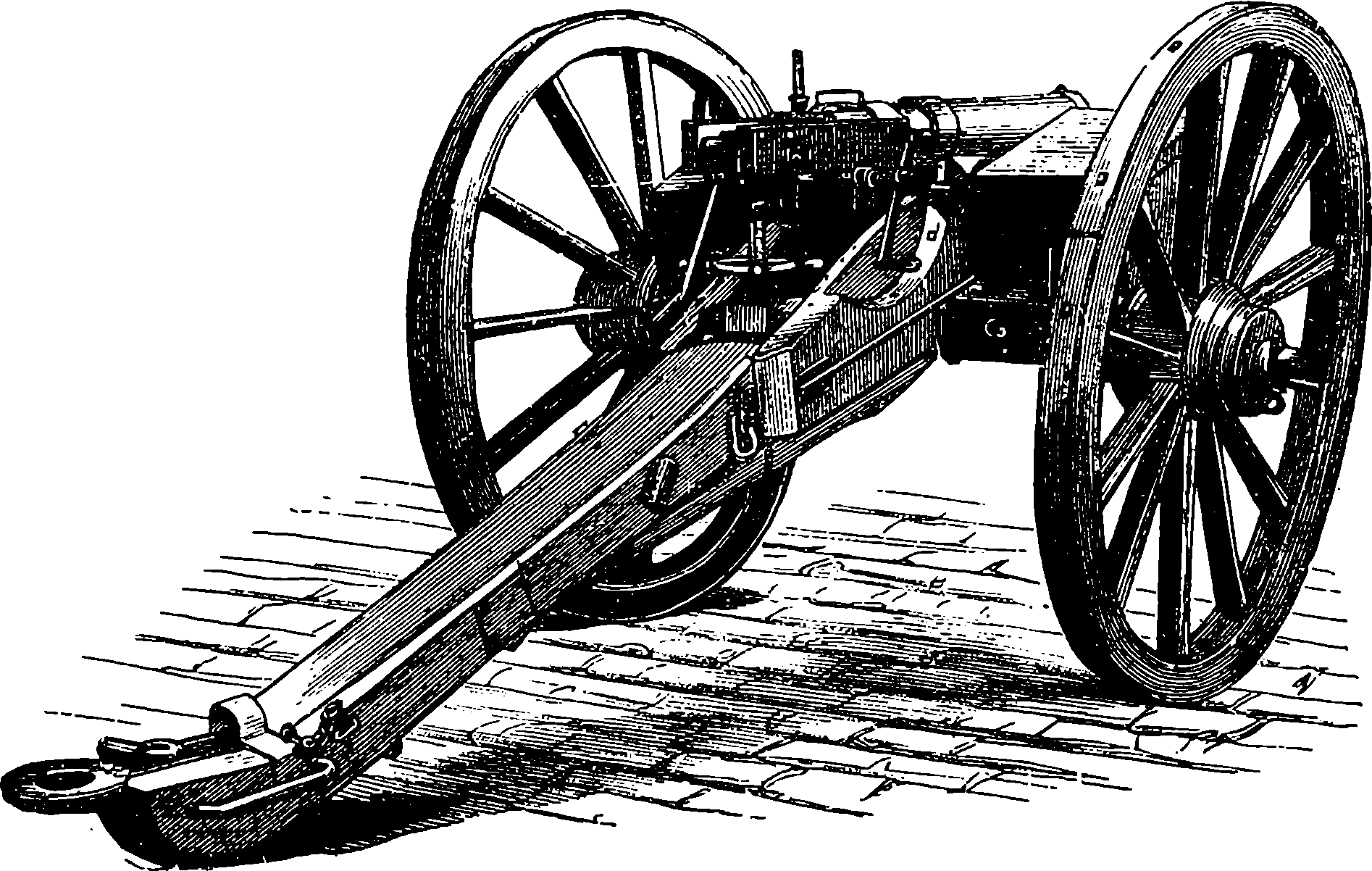
Fig. 105d.—The Montigny Mitrailleur.
A competitor to the Gatling presents itself in the Belgian mitrailleur, the Montigny, Fig. 105d. This gun, like the Gatling, is made of several different sizes, the smallest containing nineteen barrels and the largest thirty-seven. The barrels are all fitted into a wrought iron tube, which thus constitutes the compound barrel of the weapon. At the breech end of this barrel is the movable portion and the mechanism by which it is worked. The movable portion consists mainly of a short metallic cylinder of about the same diameter as the compound barrel, and this is pierced with a number of holes which correspond exactly with the position of the gun-barrels, of which they would form so many prolongations. In each of the holes or tubes a steel piston works freely; and when its front end is made even with the front surface of the short cylinder, a spiral spring, which is also contained in each of the tubes, is compressed. The short cylinder moves as a whole backwards and forwards in the direction of the axis of the piece, the movement being given by a lever to the shorter arm of which the movable piece is attached. When the gun is to be loaded this piece is drawn backwards by raising the lever, when the spiral springs are relieved 223from compression, and the heads of the pistons press lightly against a flat steel plate in front of them. The withdrawal of the breech-block gives space for a steel plate, bored with holes corresponding to the barrels, to be slid down vertically; and this plate holds in each hole a cartridge, the head of each cartridge being, when the plate has dropped into its position, exactly opposite to the barrel, into which it is thrust, when the movable breech-block is made to advance. The anterior face of this breech-block is formed of a plate containing a number of holes again corresponding to the barrels, and in each hole is a little short rod of metal, which has in front a projecting point that can be made to protrude through a small aperture in the front of the plate, the said small apertures exactly agreeing in position with the centres of the barrels, and being the only perforations in the front of the plate. The back of the plate has also openings through which the heads of the pistons can pass, and by hitting the little pieces, or strikers, cause their points to pass out through the apertures in front of the plate, and enter the base of the cartridges, where fulminate is placed. The plate filled with cartridges has a bevelled edge, and the points of the strikers are pushed back by it as it descends. The heads of the pistons are separated until the moment of discharge from the recesses containing the strikers by the flat steel plate or shutter already mentioned. The effect, therefore, of pushing the breech-block forward is to ram the cartridges into the barrels, and at the same time the spiral springs are compressed, and the heads of the pistons press against the steel shutter which separates them from the strikers, so that the whole of the breech mechanism is thus closed up. When the piece is to be fired a handle is turned, which draws down the steel shutter and permits the pistons to leap forward one by one, and hit the strikers, so that the points of the latter enter the cartridges and inflame the fulminate. The shutter is cut at its upper edge into steps, so that no two adjoining barrels are fired at once. The whole of the thirty-seven barrels can be fired by one and a quarter turns of the handle, which may, of course, be given almost instantly, or, by a slower movement, the barrels can be discharged at any required rate.
The barrels of the machine guns we have described do not, as is generally supposed, radiate; on the contrary, they are arranged in a perfectly parallel direction. In consequence of this, the bullets are at short ranges directed nearly to one spot. The Gatling gun was adopted as a service weapon by the British navy, and in several minor actions it had proved effective, but in its original form it was superseded by the Gardner gun, in which the barrels are fixed horizontally side by side, and are in number five or fewer; each barrel is able to fire 120 rounds per minute. A new system of feed was afterwards applied to the Gatling gun by Mr. Accles, by means of which this gun was greatly improved and its rate of firing was increased to more than 1,000 rounds per minute; indeed, 80 rounds have been fired from it within 2 seconds. The Gatlings in this improved form have ten barrels, and are provided with feed drums, each containing 104 cartridges, and capable, when empty, of being almost instantly replaced by a full one. The contents of one drum can, if necessary, be discharged in about 2¼ seconds, so that in this time 104 rifle bullets would be fired; or considerably more than the rate of 1,000 rounds per minute could easily be maintained. The weapon is so mounted, that without moving its carriage it can be pointed at any angle of elevation or depression, and through a considerable lateral range.
Mr. Nordenfelt has brought out a machine gun, which, on account of 224the simplicity and strength of its firing mechanism, has proved the most reliable weapon of its class, and it also has been adopted into the British service, and indeed into that of nearly every nation in the world. In this gun there are five barrels arranged as in the Gardner, but the firing is operated by a lever working backwards and forwards at the rate of 600 rounds per minute.
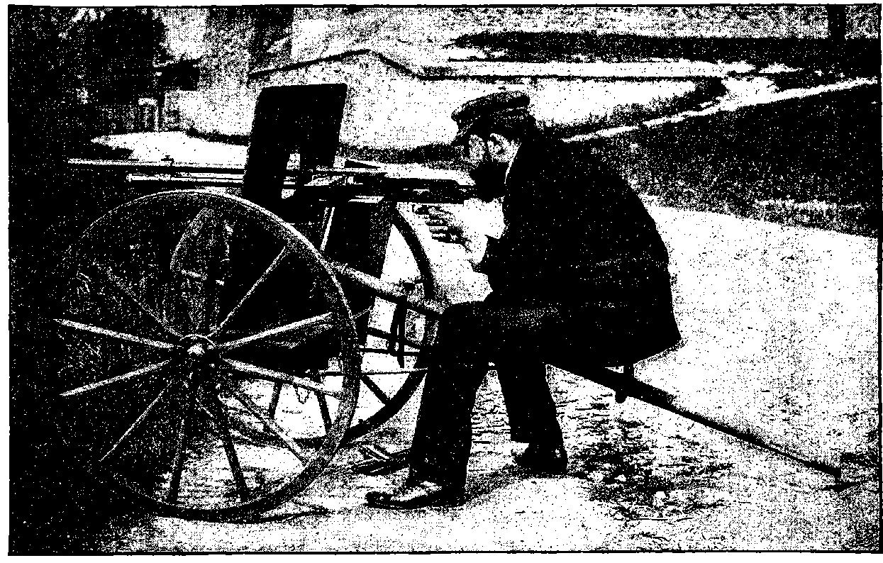
Fig. 105e.—A Hotchkiss Gun.
In the firing of all these weapons, by turning a crank, or moving a lever at one side, any attempt at exact aiming must obviously be difficult if not impossible, from the liability of the gun to get moved. Several designs have been proposed for making the firing mechanism entirely automatic so as to require no effort on the part of the firer, whose attention can then be directed solely to pointing the piece. It would not be 225easy to explain in detail the way in which this is accomplished in these very ingenious guns; for while the principle of their action is sufficiently clear, namely, that the force of the recoil is made to extract the spent cartridge, open the breech, insert a fresh cartridge, close the breech, and fire the charge, the mechanism of the reacting springs, etc., by which this is effected could scarcely, even by the aid of elaborate diagrams, be made intelligible to any other than a gunsmith. The Maxim is one of those automatic guns: it has but one barrel, and after the first discharge it will go on firing with marvellous rapidity the cartridges supplied to it in a continuous chain, and this without any deviation from such direction as may be given to it by the operator, for he has neither crank to turn nor lever to move, but merely sits behind an iron shield directing the weapon at will, which, without interference, fires hundreds of shots per minute from one barrel, so long as the long bands of cartridges are supplied to it.
Mr. Nordenfelt and Mr. Hotchkiss have also both contrived quick firing guns for 1–lb., 3–lb., and 6–lb. projectiles, and these, it has been thought, will be of great service in naval warfare as against torpedo boats.
Though the automatic mechanism, whereby the breech operations are all performed by the force of the recoil of the barrel, which is allowed to slide backwards, and is then returned to its place by a spring, is too complicated for illustration here, mention may be made of a quite recent device by which the recoil action is dispensed with, and the mechanism so far simplified that scarcely more than half the number of parts in the lock mechanism are required. Imagine a closed tube beneath the barrel, parallel to it, and communicating with it only by a small boring near the muzzle; through this opening the expanding gases will pass, in a degree depending on its size and position, and by their action on a piston near the breech, impulses are supplied that will actuate the lock mechanism so long as cartridges are supplied, as they may be in a continuous band. A weapon of this construction has been already tried, and its discharges are so rapid that the sound of them is described as being quite deafening. This plan appears to be equally applicable to small arms, and to machine or field guns. A very effective gun of the kind, which fires ordinary rifle bullets, has been contrived by Mr. Hotchkiss, and is represented in Fig. 105e. It is capable of sending forth as many as 1,000 shots in one minute.
Modern ordnance has required certain modifications in the making of gunpowder, so that the original name of powder would now hardly be applicable at all. The large charges now used, if introduced in the form of fine powder, would certainly shatter the guns from the suddenness of the exploding force. Hence the material is made up into larger or smaller masses, generally rounded like small pebbles. The explosive used for the huge 110–ton guns presents itself in the form of chocolate-coloured hexagonal prisms, two or three inches long and about an inch in diameter. These are obtained by compressing the specially prepared material into moulds with a hydraulic press. The reason for this process is that, in order to obtain precision and uniformity in the effects, not only must the composition of the powder be always the same, but the size, shape, weight, and number of the several portions that make up the charge must be invariable. It has not been found possible to fire one of these monster guns many times without such signs of deterioration as 226would suggest a short “life” for each of them. But the greatest necessity for modern fire-arms is a smokeless powder or other explosive. It is obvious that the advantages of quick firing, whether of large or of small fire-arms, are greatly reduced if the soldier or gunner is prevented by smoke from taking aim. The invention of a smokeless gunpowder has several times been announced, and great advances have, indeed, been made towards its realization. Certain compositions, which appeared to meet the requirement of being practically smokeless, have, however, been found liable to chemical changes, or to corrode the bore, or to possess other objectionable properties. In this country the explosive coming into use as best adapted for quick firing guns, etc., presents itself in appearance like whitish or grey strings, and has hence received the name of cordite. The composition and mode of manufacture of these new substitutes for gunpowder are not readily disclosed, each military authority jealously guarding its own secrets. The problem of smokeless powder has, however, been almost completely solved, for at a military review that took place on the Continent in 1889, the discharge of the rifles (loaded with blank cartridges, of course) is said to have been attended with no more smoke than the puff of a cigar. The new invention will cause some changes in military tactics, for the manœuvres formerly executed under cover of the battle smoke will no longer be possible. Some particulars as to the nature of smokeless powders will be found in the article on “Explosives.”
227
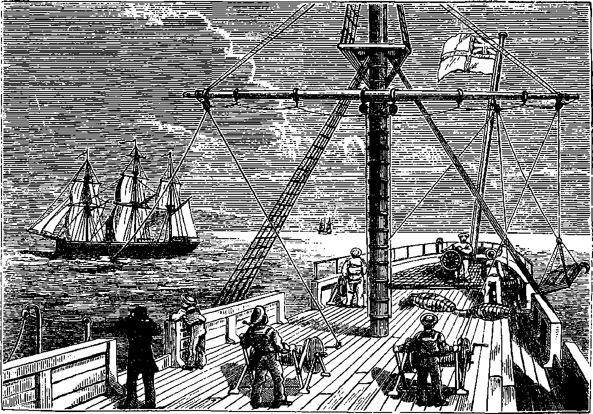
Fig. 106.—Harvey’s Torpedo. Working the Brakes.