HANGING AND DRIVING MILL IRONS.
Reading edition
FIG. 1 FIG. 2 FIG. 3.
Patented September 4, 1866, and August 1, 1871.
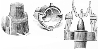
We do not think it necessary to write at length on the advantages of this improvement, nor print our files of recommendatory letters. The necessity among intelligent millers and mill-owners for a good and durable self-tramming driving iron is already well established. Many attempts have been made to devise something for the purpose, and the results are numerous; among them the “slip driver,” and those with loose oscillating appendages for the weight of the stone to rest upon and be driven by, and when adapted to their work, imperfectly accomplish the design; their lack of durability, the obstruction presented to the free passage of grain or middlings to be ground, and the fact that their form does not admit of a free adjustment while driving the stone are the chief objections. It has been established that these faults are entirely avoided by the improvement illustrated in the accompanying cut, in which Fig. 1 is an elevation showing the iron ready to be cemented in the eye of the runner. Fig. 2 is a view of the bottom and inside, with the sockets for the reception of the ends of the driver. Fig. 3 is a sectional elevation of all the parts, including the spindle and driver.
The bridge S S, in which the steel cock-eye is placed, is in the form of an inverted arch, and is a portion of the entire outside part. Being in this shape, it has the double advantage of increased strength, and, by the attachment above the point where the grain is distributed, making no obstruction whatever to the passage of the grain or other substance to be ground. The bearings for the ends of the driver, C C, are cast on the adjustable section of the iron shown on the inner part of Fig. 2. This being adjustable on the steel pins shown as passing through the lugs A A, gives to the ends of the driver at all times a free and equal bearing in a lateral direction. The object gained by this arrangement is the application of power by the driver to the inner section in a direct plane, parallel to the face of the runner stone, said plane at the same time passing through the cock-eye—hence there is no tendency whatever to tip the stone.
When the ordinary spindle with stiff driver is put in tram to the face of the runner, the miller has no assurance that it will remain so, the chances, indeed, being constantly against it. The heaviest spindle is liable to spring from its true position by the pressure of the gear or belt in driving it; the face of the runner stone changes, and the best driver, or its bearings, will from unequal wearing of the metal or in other ways cause it to get out of tram. The results are uneven grinding, inferior flour and diminished yield. The trouble necessary to take the spindle out, turn over the runner, make a staff and file the ends of the driver, is generally sufficient to deter the miller from performing the disagreeable job, and the bad grinding is conveniently attributed to some other difficulty.
Among the advantages offered by this improvement are increased grinding capacity with a given amount of power, more even grinding and better yield, and lastly, but not less important, increased facility in obtaining a perfect running balance. It will be observed that the runner is supported upon a steel seat secured in the stone permanently—being substantially the same in this respect as when the ordinary balance-iron is used.
The power being transmitted to the stone by the adjustable part of the iron and no weight upon any part of it, with the entire structure of the form to give the greatest attainable firmness and durability, combine to make it perfection as a driving iron, and it is accordingly in extensive use, although no especial effort has been made until late for their manufacture and sale. They are made in the best manner by skillful men and machinery adapted for the purpose, the parts well fitted and turned true inside where the grain enters and passes.
They are made of the following sizes: 8½, 10 and 12 inches diameter.
To order for attaching to stones with other irons already in, give diameter of the eye in stone at the face.
Distance from the cock-head point to the lower side of the driver.
Shape of cock-head as near as you can.
Shape and exact size of spindle where your present driver goes on.
In getting the shape as well as size of place where your present driver fits, it is a good plan to oil the inside surface of the hole in driver (in which the spindle fits) and fill it with plaster, then take out and send the cast by express. The shape of cock-head may be got by similar process.
We will send necessary instructions, so that any one of medium skill can put them in at the mill.
Give names, post office, county, and shipping point plainly, and how you wish to pay us. Money sent by Post Office Order is safe, and payment with the order always saves delay and trouble of making out bills, book-entries, &c. To those whose faith is not sufficient, will send the irons on trial or as circumstances best suggest at the time.
The safe arrival of them is guaranteed. Every iron is warranted.
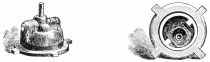
Fig. 1. Fig. 2.
These two cuts are intended to represent the self-tram irons for our under-runner mills. Fig. 1 shows the form of the outside, as it appears before being bedded in the centre, and iron back of the runner stone. Fig. 2 is a view of the inside, showing where the point of the spindle and driver rest.