COMPLETE PORTABLE GRINDING AND BOLTING FLOURING MILLS.
Reading edition
The cuts, Figs. 1, 2, 3 and 4, are intended to show the different arrangements in buildings and are made by us of the following sizes of stones: 30, 36 and 42 inches diameter of upper-runners, and 26, 30 and 36 inch of the under-runner kind, with the bolts described fully elsewhere, of ample capacity and to meet the special demands of a custom mill, capable of making flour that will bear inspection in any market, at the same time good yields, and are as economical in the use of power as any mill in the United States. Drawings and directions to set up sent with each mill when ordered. It betters the arrangement to place the husk frame 20 inches below the floor; the discharge spout and hoppers all come at a convenient height for the miller to see into the hopper and operate the mill without stooping. In Figs. 1 and 3 they are shown thus. We advise making a platform in the rear of the mills over the belts. The stones and bolt-chest can be placed on same floor, as Fig. 1, or the bolt above as the situation requires. They will grind and bolt from six to fifteen bushels per hour according to size, and can be put in operation in a short time, and are no more liable to get out of repair than the best mill in use.
Those having their power all ready, should give us the dimensions of it and kind, to enable us to give correct information as to size of mill best adapted to it, &c., &c.
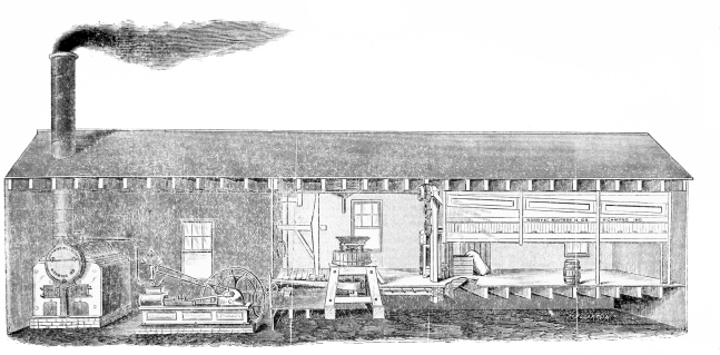
Fig. 1.
The above shows our Portable Mills, arranged in one story house and driven by Reel Belts and Tightening Rigging to Shift Belts. For Ground Plan, See Fig. 4.
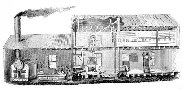
Fig. 2.
Portable Mills driven by quarter twist Belts without the tightening rigging. For Ground Plan, See Fig. 4.
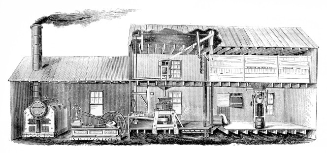
Fig. 3.
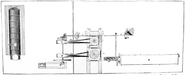
Fig. 4.
This Ground Plan view applies to Figs. 1, 2 and 3. Line Shaft, S S, Bolt at B, &c., is located above. Foundation Timbers, D D and Cooling Conveyor, E, is under lower floor.
Fig. 5.
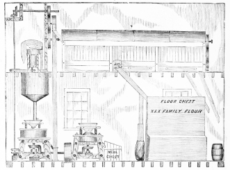
This engraving represents two geared Mills with their attendant machinery as arranged in the Mill Building, Warehouse, or any house suitable. The application of the Power to be by belt from Engine or Water Power to the Large Pulley between two Mills.
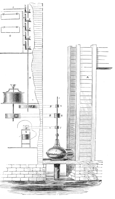
Fig. 6. WATER MILL, Driven by Belts under high head, with Wheel in Iron Casing.
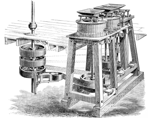
Fig. 7. COMBINED MILL HUSK. See Page 31.