Volume 1 — CHAPTER XXI
Reading edition
THE SIMPLE MAGNETO SWITCHBOARD
Definitions. As already stated those switchboards which are adapted to work in conjunction with magneto telephones are called magneto switchboards. The signals on such switchboards are electromagnetic devices capable of responding to the currents of the magneto generators at the subscribers' stations. Since, as a rule, magneto telephones are equipped with local batteries, it follows that the magneto switchboard does not need to be arranged for supplying the subscribers' stations with talking current. This fact is accountable for magneto switchboards often being referred to as local-battery switchboards, in contradistinction to common-battery switchboards which are equipped so as to supply the connected subscribers' stations with talking current.
The term simple as applied in the headings of this and the next chapter, is employed to designate switchboards adapted for so small a number of lines that they may be served by a single or a very small group of operators; each line is provided with but a single connection terminal and all of them, without special provision, are placed directly within the reach of the operator, or operators if there are more than one. This distinction will be more apparent under the discussion of transfer and multiple switchboards.
Mode of Operation. The cycle of operation of any simple manual switchboard may be briefly outlined as follows: The subscriber desiring a connection transmits a signal to the central office, the operator seeing the signal makes connection with the calling line and places herself in telephonic communication with the calling subscriber to receive his orders; the operator then completes the connection with the line of the called subscriber and sends ringing current out on that line so as to ring the bell of that subscriber; the two subscribers then converse over the connected lines and when the conversation is finished either one or both of them may send a signal to the central office for disconnection, this signal being called a clearing-out signal; upon receipt of the clearing-out signal, the operator disconnects the two lines and restores all of the central-office apparatus involved in the connection to its normal position.
Component Parts. Before considering further the operation of manual switchboards it will be well to refer briefly to the component pieces of apparatus which go to make up a switchboard.
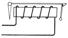
Line Signal. The line signal in magneto switchboards is practically always in the form of an electromagnetic annunciator or drop. It consists in an electromagnet adapted to be included in the line circuit, its armature controlling a latch, which serves to hold the drop or shutter or target in its raised position when the magnet is not energized, and to release the drop or shutter or target so as to permit the display of the signal when the magnet is energized. The symbolic representation of such an electromagnetic drop is shown in Fig. 233.
Fig. 233. Drop Symbol View full size illustration.
Jacks and Plugs. Each line is also provided with a connection terminal in the form of a switch socket. This assumes many forms, but always consists in a cylindrical opening behind which are arranged one or more spring contacts. The opening forms a receptacle for plugs which have one or more metallic terminals for the conductors in the flexible cord in which the plug terminates. The arrangement is such that when a plug is inserted into a jack the contacts on the plug will register with certain of the contacts in the jack and thus continue the line conductors, which terminate in the jack contacts, to the cord conductors, which terminate in the plug contacts. Usually also when a plug is inserted certain of the spring contacts in the jack are made to engage with or disengage other contacts in the jack so as to make or break auxiliary circuits.
Fig. 234. Spring Jack View full size illustration.
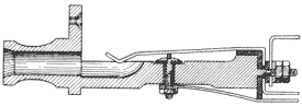
A simple form of spring jack is shown in section in Fig. 234. In Fig. 235 is shown a sectional view of a plug adapted to co-operate with the jack of Fig. 234. In Fig. 236 the plug is shown inserted into the jack. The cylindrical portion of the jack is commonly called the sleeve or thimble and it usually forms one of the main terminals of the jack; the spring, forming the other principal terminal, is called the tip spring, since it engages the tip of the plug. The tip spring usually rests on another contact which may be termed the anvil. When the plug is inserted into the jack as shown in Fig. 236, the tip spring is raised from contact with this anvil and thus breaks the circuit leading through it. It will be understood that spring jacks are not limited to three contacts such as shown in these figures nor are plugs limited to two contacts. Sometimes the plugs have three, and even more, contacts, and frequently the jacks corresponding to such plugs have not only a contact spring adapted to register with each of the contacts of the plug, but several other auxiliary contacts also, which will be made or broken according to whether the plug is inserted or withdrawn from the jack. Symbolic representations of plugs and jacks are shown in Fig. 237. These are employed in diagrammatic representations of circuits and are supposed to represent the essential elements of the plugs and jacks in such a way as to be suggestive of their operation. It will be understood that such symbols may be greatly modified to express the various peculiarities of the plugs and jacks which they represent.
Fig. 235. Plug View full size illustration.
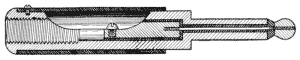
Fig. 236. Plug and Jack View full size illustration.
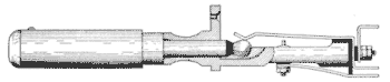
Fig. 237. Jack and Plug Symbols View full size illustration.
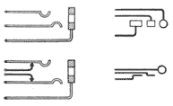
Keys. Other important elements of manual switchboards are ringing and listening keys. These are the devices by means of which the operator may switch the central-office generator or her telephone set into or out of the circuit of the connected lines. The details of a simple ringing and listening key are shown in Fig. 238. This consists of two groups of springs, one of four and one of six, the springs in each group being insulated from each other at their points of mounting. Two of these springs 1 and 2 in one group—the ringing group—are longer than the others, and act as movable levers engaging the inner pair of springs 3 and 4 when in their normal positions, and the outer pair 5 and 6 when forced into their alternate positions. Movement is imparted to these springs by the action of a cam which is mounted on a lever, manipulated by the operator. When this lever is moved in one direction the cam presses the two springs 1 and 2 apart, thus causing them to disengage the springs 3 and 4 and to engage the springs 5 and 6.
Fig. 238. Ringing and Listening Key View full size illustration.
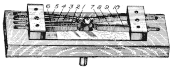
The springs of the other group constitute the switching element of the listening key and are very similar in their action to those of the ringing key, differing in the fact that they have no inner pair of springs such as 3 and 4. The two long springs 7 and 8, therefore, normally do not rest against anything, but when the key lever is pressed, so as to force the cam between them, they are made to engage the two outer springs 9 and 10.
Fig. 239. Ringing-and Listening-Key Symbols View full size illustration.
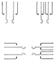
The design and construction of ringing and listening keys assume many different forms. In general, however, they are adapted to do exactly the same sort of switching operations as that of which the device of Fig. 238 is capable. Easily understood symbols of ringing and listening keys are shown in Fig. 239; the cam member which operates on the two long springs is usually omitted for ease of illustration. It will be understood in considering these symbols, therefore, that the two long curved springs usually rest against a pair of inner contacts in case of the ringing key or against nothing at all in case of the listening key, and that when the key is operated the two springs are assumed to be spread apart so as to engage the outer pair of contacts with which they are respectively normally disconnected.
Line and Cord Equipments. The parts of the switchboard that are individual to the subscriber's line are termed the line equipment; this, in the case of a magneto switchboard, consists of the line drop and the jack together with the associated wiring necessary to connect them properly in the line circuit. The parts of the switchboard that are associated with a connecting link—consisting of a pair of plugs and associated cords with their ringing and listening keys and clearing-out drop—are referred to as a cord equipment. The circuit of a complete pair of cords and plugs with their associated apparatus is called a cord circuit. In order that there may be a number of simultaneous connections between different pairs of lines terminating in a switchboard, a number of cord circuits are provided, this number depending on the amount of traffic at the busiest time of the day.
Operator's Equipment. A part of the equipment that is not individual to the lines or to the cord circuits, but which may, as occasion requires, be associated with any of them is called the operator's equipment. This consists of the operator's transmitter and receiver, induction coil, and battery connections together with the wiring and other associated parts necessary to co-ordinate them with the rest of the apparatus. Still another part of the equipment that is not individual to the lines nor to the cord circuits is the calling-current generator. This may be common to the entire office or a separate one may be provided for each operator's position.
Operation in Detail. With these general statements in mind we may take up in some detail the various operations of a telephone system wherein the lines center in a magneto switchboard. This may best be done by considering the circuits involved, without special regard to the details of the apparatus.
The series of figures showing the cycle of operations of the magneto switchboard about to be discussed are typical of this type of switchboard almost regardless of make. The apparatus is in each case represented symbolically, the representations indicating type rather than any particular kind of apparatus within the general class to which it belongs.
Normal Condition of Line. In Fig. 240 is shown the circuit of an ordinary magneto line. The subscriber's sub-station apparatus, shown at the left, consists of the ordinary bridging telephone but might with equal propriety be indicated as a series telephone. The subscriber's station is shown connected with the central office by the two limbs of a metallic-circuit line. One limb of the line terminates in the spring 1 of the jack, and the other limb in the sleeve or thimble 2 of the jack. The spring 1 normally rests on the third contact or anvil 3 in the jack, its construction being such that when a plug is inserted this spring will be raised by the plug so as to break contact with the anvil 3. It is understood, of course, that the plug associated with this jack has two contacts, referred to respectively as the tip and the sleeve; the tip makes contact with the tip spring 1 and the sleeve with the sleeve or thimble 2.
Fig. 240. Normal Condition of Line View full size illustration.
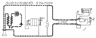
The drop or line signal is permanently connected between the jack sleeve and the anvil 3. As a result, the drop is normally bridged across the circuit of the line so as to be in a receptive condition to signaling current sent out by the subscriber. It is evident, however, that when the plug is inserted into the jack this connection between the line and the drop will be broken.
In this normal condition of the line, therefore, the drop stands ready at the central office to receive the signal from the subscriber and the generator at the sub-station stands ready to be bridged across the circuit of the line as soon as the subscriber turns its handle. Similarly the ringer—the call-receiving device at the sub-station—is permanently bridged across the line so as to be responsive to any signal that may be sent out from the central office in order to call the subscriber. The subscriber's talking apparatus is, in this normal condition of the line, cut out of the circuit by the switch hook.
Subscriber Calling. Fig. 241 shows the condition of the line when the subscriber at the sub-station is making a call. In turning his generator the two springs which control the connection of the generator with the line are brought into engagement with each other so that the generator currents may pass out over the line. The condition at the central office is the same as that of Fig. 240 except that the drop is shown with its shutter fallen so as to indicate a call.
Fig. 241. Subscriber Calling View full size illustration.
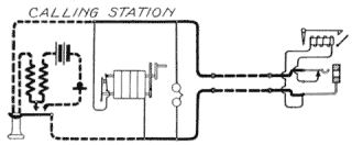
Operator Answering. The next step is for the operator to answer the call and this is shown in Fig. 242. The subscriber has released the handle of his generator and the generator has, therefore, been automatically cut out of the circuit. He also has removed his receiver from its hook, thus bringing his talking apparatus into the line circuit. The operator on the other hand has inserted one of the plugs Pa into the jack. This action has resulted in the breaking of the circuit through the drop by the raising of the spring 1 from the anvil 3, and also in the continuance of the line circuit through the conductors of the cord circuits. Thus, the upper limb of the line is continued by means of the engagement of the tip spring 1 with the tip 4 of the plug to the conducting strand 6 of the cord circuit; likewise the lower limb of the line is continued by the engagement of the thimble 2 of the jack with the sleeve contact 5 of the plug Pa to the strand 7 of the cord circuit. The operator has also closed her listening key L.K. In doing so she has brought the springs 8 and 9 into engagement with the anvils 10 and 11 and has thus bridged her head telephone receiver with the secondary of her induction coil across the two strands 6 and 7 of the cord. Associated with the secondary winding of her receiver is a primary circuit containing a transmitter, battery, and the primary of the induction coil. It will be seen that the conditions are now such as to permit the subscriber at the calling station to converse with the operator and this conversation consists in the familiar "Number Please" on the part of the operator and the response of the subscriber giving the number of the line that is desired. Neither the plug Pc, nor the ringing key R.K., shown in Fig. 242, is used in this operation. The clearing-out drop C.O. is bridged permanently across the strands 6-7 of the cord, but is without function at this time; the fact that it is wound to a high resistance and impedance prevents its having a harmful effect on the transmission.
Fig. 242. Operator Answering View full size illustration.
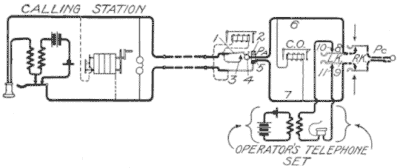
It may be stated at this point that the two plugs of an associated pair are commonly referred to as the answering and calling plugs. The answering plug is the one which the operator always uses in answering a call as just described in connection with Fig. 242. The calling plug is the one which she next uses in connecting with the line of the called subscriber. It lies idle during the answering of a call and is only brought into play after the order of the calling subscriber has been given, in which case it is used in establishing connection with the called subscriber.
Fig. 243. Operator Calling View full size illustration.
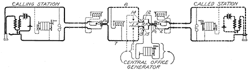
Operator Calling. We may now consider how the operator calls the called subscriber. The condition existing for this operation is shown in Fig. 243. The operator after receiving the order from the calling subscriber inserts the calling plug Pc into the jack of the line of the called station. This act at once connects the limbs of the line with the strands 6 and 7 of the cord circuit, and also cuts out the line drop of the called station, as already explained. The operator is shown in this figure as having opened her listening key L.K. and closed her ringing key R.K. As a result, ringing current from the central-office generator will flow out over the two ringing key springs 12 and 13 to the tip and sleeve contacts of the calling plug Pc, then to the tip spring 1 and the sleeve or thimble 2 of the jack, and then to the two sides of the metallic-circuit line to the sub-station and through the bell there. This causes the ringing of the called subscriber's bell, after which the operator releases the ringing key and thereby allows the two springs 12 and 13 of that key to again engage their normal contacts 14 and 15, thus making the two strands 6 and 7 of the cord circuit continuous from the contacts of the answering plug Pa to the contacts of the calling plug Pc. This establishes the condition at the central office for conversation between the two subscribers.
Fig. 244. Subscribers Connected for Conversation View full size illustration.

Subscribers Conversing. The only other thing necessary to establish a complete set of talking conditions between the two subscribers is for the called subscriber to remove his receiver from its hook, which he does as soon as he responds to the call. The conditions for conversation between the two subscribers are shown in Fig. 244. It is seen that the two limbs of the calling line are connected respectively to the two limbs of the called line by the two strands of the cord circuit, both the operator's receiver and the central-office generator being cut out by the listening and ringing keys, respectively. Likewise the two line drops are cut out of circuit and the only thing left associated with the circuit at the central office is the clearing-out drop C. O., which remains bridged across the cord circuit. This, like the two ringers at the respective connected stations, which also remain bridged across the circuit when bridging instruments are used, is of such high resistance and impedance that it offers practically no path to the rapidly fluctuating voice currents to leak from one side of the line circuit to the other. Fluctuating currents generated by the transmitter at the calling station, for instance, are converted by means of the induction coil into alternating currents flowing in the secondary of the induction coil at that station. Considering a momentary current as passing up through the secondary winding of the induction coil at the calling station, it passes through the receiver of that station through the upper limb of the line to the spring 1 of the line jack belonging to that line at the central office; thence through the tip 4 of the answering plug to the conductor 6 of the cord; thence through the pair of contacts 14 and 12 forming one side of the ringing key to the tip 4 of the calling plug; thence to the tip spring 1 of the jack of the called subscriber's line; thence over the upper limb of his line through his receiver and through the secondary of the induction to one of the upper switch-hook contacts; thence through the hook lever to the lower side of the line, back to the central office and through the sleeve contact 2 of the jack and the sleeve contact 5 of the plug; thence through the other ringing key contacts 13 and 15; thence through the strand 7 of the cord to the sleeve contact 5 and the sleeve contact 2 of the answering plug and jack, respectively; thence through the lower limb of the calling subscriber's line to the hook lever at his station; thence through one of the upper contacts of this hook to the secondary of the induction coil, from which point the current started.
Fig. 245. Clearing-Out Signal View full size illustration.

Obviously, when the called subscriber is talking to the calling subscriber the same path is followed. It will be seen that at any time the operator may press her listening key L.K., bridge her telephone set across the circuit of the two connected lines, and listen to the conversation or converse with either of the subscribers in case of necessity.
Clearing Out. At the close of the conversation, either one or both of the subscribers may send a clearing-out signal by turning their generators after hanging up their receivers. This condition is shown in Fig. 245. The apparatus at the central office remains in exactly the same position during conversation as that of Fig. 244, except that the clearing-out drop shutter is shown as having fallen. The two subscribers are shown as having hung up their receivers, thus cutting out their talking apparatus, and as operating their generators for the purpose of sending the clearing-out signals. In response to this act the operator pulls down both the calling and the answering plug, thus restoring them to their normal seats, and bringing both lines to the normal condition as shown in Fig. 240. The line drops are again brought into operative relation with their respective lines so as to be receptive to subsequent calls and the calling generators at the sub-stations are removed from the bridge circuits across the line by the opening of the automatic switch contacts associated with those generators.
Essentials of Operation. The foregoing sequence of operations while described particularly with respect to magneto switchboards is, with certain modifications, typical of the operation of nearly all manual switchboards. In the more advanced types of manual switchboards, certain of the functions described are sometimes done automatically, and certain other functions, not necessary in connection with the simple switchboard, are added. The essential mode of operation, however, remains the same in practically all manual switchboards, and for this reason the student should thoroughly familiarize himself with the operation and circuits of the simple switchboard as a foundation for the more complex and consequently more-difficult-to-understand switchboards that will be described later on.
Commercial Types of Drops and Jacks. Early Drops. Coming now to the commercial types of switchboard apparatus, the first subject that presents itself is that of magneto line signals or drops. The very early forms of switchboard drops had, in most cases, two-coil magnets, the cores of which were connected at their forward ends by an iron yoke and the armature of which was pivoted opposite the rear end of the two cores. To the armature was attached a latch rod which projected forwardly to the front of the device and was there adapted to engage the upper edge of the hinged shutter, so as to hold it in its raised or undisplayed position when the armature was unattracted. Such a drop, of Western Electric manufacture, is shown in Fig. 246.
Fig. 246 Old-Style Drop View full size illustration.
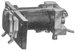
Liability to Cross-Talk:—This type of drop is suitable for use only on small switchboards where space is not an important consideration, and even then only when the drop is entirely cut out of the circuit during conversation. The reason for this latter requirement will be obvious when it is considered that there is no magnetic shield around the winding of the magnet and no means for preventing the stray field set up by the talking currents in one of the magnets from affecting by induction the windings of adjacent magnets contained in other talking circuits. Unless the drops are entirely cut out of the talking circuit, therefore, they are very likely to produce cross-talk between adjacent circuits. Furthermore, such form of drop is obviously not economical of space, two coils placed side by side consuming practically twice as much room as in the case of later drops wherein single magnet coils have been made to answer the purpose.
Tubular Drops. In the case of line drops, which usually can readily be cut out of the circuit during conversation, this cross-talk feature is not serious, but sometimes the line drops, and always the clearing-out drops must be left in connection with the talking circuit. On account of economy in space and also on account of this cross-talk feature, there has come into existence the so-called tubular or iron-clad drop, one of which is shown in section in Fig. 247. This was developed a good many years ago by Mr. E.P. Warner of the Western Electric Company, and has since, with modifications, become standard with practically all the manufacturing companies. In this there is but a single bobbin, and this is enclosed in a shell of soft Norway iron, which is closed at its front end and joined to the end of the core as indicated, so as to form a complete return magnetic path for the lines of force generated in the coil. The rear end of the shell and core are both cut off in the same plane and the armature is made in such form as to practically close this end of the shell. The armature carries a latch rod extending the entire length of the shell to the front portion of the structure, where it engages the upper edge of the pivoted shutter; this, when released by the latch upon the attraction of the armature, falls so as to display a target behind it.
Fig. 247. Tubular Drop View full size illustration.
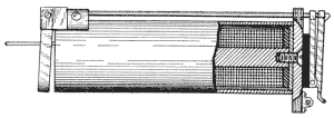
Fig. 248. Strip of Tubular Drops View full size illustration.
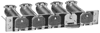
These drops may be mounted individually on the face of the switchboard, but it is more usual to mount them in strips of five or ten. A strip of five drops, as manufactured by the Kellogg Switchboard and Supply Company, is shown in Fig. 248. The front strip on which these drops are mounted is usually of brass or steel, copper plated, and is sufficiently heavy to provide a rigid support for the entire group of drops that are mounted on it. This construction greatly facilitates the assembling of the switchboard and also serves to economize space—obviously, the thing to economize on the face of a switchboard is space as defined by vertical and horizontal dimensions. These tubular drops, having but one coil, are readily mounted on 1-inch centers, both vertically and horizontally. Sometimes even smaller dimensions than this are secured. The greatest advantage of this form of construction, however, is in the absolute freedom from cross-talk between two adjacent drops. So completely is the magnetic field of force kept within the material of the shell, that there is practically no stray field and two such drops may be included in two different talking circuits and the drops mounted immediately adjacent to each other without producing any cross-talk whatever.
Night Alarm. Switchboard drops in falling make but little noise, and during the day time, while the operator is supposed to be needed continually at the board, the visual signal which they display is sufficient to attract her attention. In small exchanges, however, it is frequently not practicable to keep an operator at the switchboard at night or during other comparatively idle periods, and yet calls that do arrive during such periods must be attended to. For this reason some other than a visual signal is necessary, and this need is met by the so-called night-alarm attachment. This is merely an arrangement by which the shutter in falling closes a pair of contacts and thus completes the circuit of an ordinary vibrating bell or buzzer which will sound until the shutter is restored to its normal position. Such contacts are shown in Fig. 249 at 1 and 2. Night-alarm contacts have assumed a variety of forms, some of which will be referred to in the discussion of other types of drops and jacks.
Fig. 249. Drop with Night-Alarm Contacts View full size illustration.
Jack Mounting. Jacks, like drops, though frequently individually mounted are more often mounted in strips. An individually mounted jack is shown in Fig. 250, and a strip of ten jacks in Fig. 251. In such a strip of jacks, the strips supporting the metallic parts of the various jacks are usually of hard rubber reinforced by brass so as to give sufficient strength. Various forms of supports for these strips are used by different manufacturers, the means for fastening them in the switchboard frame usually consisting of brass lugs on the end of the jack strip adapted to be engaged by screws entering the stationary portion of the iron framework; or sometimes pins are fixed in the framework, and the jack is held in place by nuts engaging screw-threaded ends on such pins.
Fig. 250. Individual Jack View full size illustration.
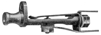
Fig. 251. Strip of Jacks View full size illustration.
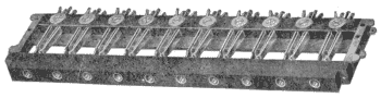
Methods of Associating Jacks and Drops. There are two general methods of arranging the drops and jacks in a switchboard. One of these is to place all of the jacks in a group together at the lower portion of the panel in front of the operator and all of the drops together in another group above the group of jacks. The other way is to locate each jack in immediate proximity to the drop belonging to the same line so that the operator's attention will always be called immediately to the jack into which she must insert her plug in response to the display of a drop. This latter practice has several advantages over the former. Where the drops are all mounted in one group and the jacks in another, an operator seeing a drop fall must make mental note of it and pick out the corresponding jack in the group of jacks. On the other hand, where the jacks and drops are mounted immediately adjacent to each other, the falling of a drop attracts the attention of the operator to the corresponding jack without further mental effort on her part.
The immediate association of the drops and jacks has another advantage—it makes possible such a mechanical relation between the drop and its associated jack that the act of inserting the plug into the jack in making the connection will automatically and mechanically restore the drop to its raised position. Such drops are termed self-restoring drops, and, since a drop and jack are often made structurally a unitary piece of apparatus, they are frequently called combined drops and jacks.
Manual vs. Automatic Restoration.. There has been much difference of opinion on the question of manual versus automatic restoration of drops. Some have contended that there is no advantage in having the drops restored automatically, claiming that the operator has plenty of time to restore the drops by hand while receiving the order from the calling subscriber or performing some of her other work. Those who think this way have claimed that the only place where an automatically restored drop is really desirable is where, on account of the lack of space on the front of the switchboard, the drops are placed on such a portion of the board as to be not readily reached by the operator. This resulted in the electrically restored drop, mention of which will be made later.
Others have contended that even though the drop is mounted within easy reach of the operator, it is advantageous that the operator should be relieved of the burden of restoring it, claiming that even though there are times in the regular performance of the operator's duties when she may without interfering with other work restore the drops manually, such requirement results in a double use of her attention and in a useless strain on her which might better be devoted to the actual making of connections.
Until recently the various Bell operating companies have adhered, in their small exchange work, to the manual restoring method, while most of the so-called independent operating companies have adhered to the automatic self-restoring drops.
Methods of Automatic Restoration. Two general methods present themselves for bringing about the automatic restoration of the drop. First, the mechanical method, which is accomplished by having some moving part of the jack or of the plug as it enters the jack force the drop mechanically into its restored position. This usually means the mounting of the drop and the corresponding jack in juxtaposition, and this, in turn, has usually resulted in the unitary structure containing both the drop and the jack. Second, the electrical method wherein the plug in entering the jack controls a restoring circuit, which includes a battery or other source of energy and a restoring coil on the drop, the result being that the insertion of the plug into the jack closes this auxiliary circuit and thus energizes the restoring magnet, the armature of which pulls the shutter back into its restored position. This practice has been followed by Bell operating companies whenever conditions require the drop to be mounted out of easy reach of the operator; not otherwise.
Mechanical—Direct Contact with Plug. One widely used method of mechanical restoration of drops, once employed by the Western Telephone Construction Company with considerable success, was to hang the shutter in such position that it would fall immediately in front of the jack so that the operator in order to reach the jack with the plug would have to push the plug directly against the shutter and thus restore it to its normal or raised position. In this construction the coil of the drop magnet was mounted directly behind the jack, the latch rod controlled by the armature reaching forward, parallel with the jack, to the shutter, which, as stated, was hung in front of the jack. This resulted in a most compact arrangement so far as the space utilization on the front of the board was concerned and such combined drops and jacks were mounted on about 1-inch centers, so that a bank of one hundred combined drops and jacks occupied a space only a little over 10 inches square.
A modification of this scheme, as used by the American Electric Telephone Company, was to mount the drop immediately over the jack so that its shutter, when down, occupied a position almost in front of, but above, the jack opening. The plug was provided with a collar, which, as it entered the jack, engaged a cam on the base of the shutter and forced the latter mechanically into its raised position.
Neither of these methods of restoring—i.e., by direct contact between the shutter or part of it and the plug or part of it—is now as widely used as formerly. It has been found that there is no real need in magneto switchboards for the very great compactness which the hanging of the shutter directly in front of the drop resulted in, and the tendency in later years has been to make the combined drops and jacks more substantial in construction at the expense of some space on the face of the switchboard.
Fig. 252. Kellogg Drop and Jack View full size illustration.
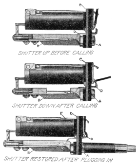
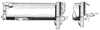
Kellogg Type:—A very widely used scheme of mechanical restoration is that employed in the Miller drop and jack manufactured by the Kellogg Switchboard and Supply Company, the principles of which may be understood in connection with Fig. 252. In this figure views of one of these combined drops and jacks in three different positions are shown. The jack is composed of the framework B and the hollow screw A, the latter forming the sleeve or thimble of the jack and being externally screw-threaded so as to engage and bind in place the front end of the framework B. The jack is mounted on the lower part of the brass mounting strip C but insulated therefrom. The tip spring of the jack is bent down as usual to engage the tip of the plug, as better shown in the lower cut of Fig. 252, and then continues in an extension D, which passes through a hole in the mounting plate C. This tip spring in its normal position rests against another spring as shown, which latter spring forms one terminal of the drop winding.
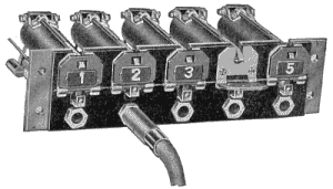
The drop or annunciator is of tubular form, and the shutter is so arranged on the front of the mounting strip C as to fall directly above the extension D of the tip spring. As a result, when the plug is inserted into the jack, the upward motion of the tip spring forces the drop into its restored position, as indicated in the lower cut of the figure. These drops and jacks are usually mounted in banks of five, as shown in Fig. 253.
Fig. 253. Strip of Kellogg Drops and Jacks View full size illustration.
Western Electric Type:—The combined drop and jack of the Western Electric Company recently put on the market to meet the demands of the independent trade, differs from others principally in that it employs a spherical drop or target instead of the ordinary flat shutter. This piece of apparatus is shown in its three possible positions in Fig. 254. The shutter or target normally displays a black surface through a hole in the mounting plate. The sphere forming the target is out of balance, and when the latch is withdrawn from it by the action of the electromagnet it falls into the position shown in the middle cut of Fig. 254, thus displaying a red instead of a black surface to the view of the operator. When the operator plugs in, the plug engages the lower part of an S-shaped lever which acts on the pivoted sphere to restore it to its normal position. A perspective view of one of these combined line signals and jacks is shown in Fig. 255.
A feature that is made much of in recently designed drops and jacks for magneto service is that which provides for the ready removal of the drop coil, from the rest of the structure, for repair. The drop and jack of the Western Electric Company, just described, embodies this feature, a single screw being so arranged that its removal will permit the withdrawal of the coil without disturbing any of the other parts or connections. The coil windings terminate in two projections on the front head of the spool, and these register with spring clips on the inside of the shell so that the proper connections for the coil are automatically made by the mere insertion of the coil into the shell.
Fig. 254. Western Electric Drop and Jack View full size illustration.
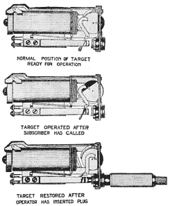
Fig. 255. Western Electric Drop and Jack View full size illustration.
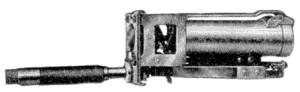
Dean Type:—The combined drop and jack of the Dean Electric Company is illustrated in Figs. 256 and 257. The two perspective views show the general features of the drop and jack and the method by which the magnet coil may be withdrawn from the shell. As will be seen the magnet is wound on a hollow core which slides over the iron core, the latter remaining permanently fixed in the shell, even though the coil be withdrawn.
Fig. 258 shows the structural details of the jack employed in this combination and it will be seen that the restoring spring for the drop is not the tip spring itself, but another spring located above and insulated from it and mechanically connected therewith.
Fig. 256. Dean Drop and Jack View full size illustration.
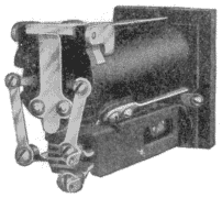
Fig. 257. Dean Drop and Jack View full size illustration.
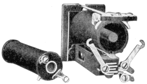
Fig. 258. Details of Dean Jack View full size illustration.
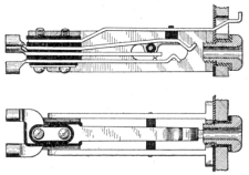
Monarch Type:—Still another combined drop and jack is that of the Monarch Telephone Manufacturing Company of Chicago, shown in sectional view in Fig. 259. This differs from the usual type in that the armature is mounted on the front end of the electromagnet, its latch arm retaining the shutter in its normal position when raised, and releasing it when depressed by the attraction of the armature. As is shown, there is within the core of the magnet an adjustable spiral spring which presses forward against the armature and which spring is compressed by the attraction of the armature of the magnet. The night-alarm contact is clearly shown immediately below the strip which supports the drop, this consisting of a spring adapted to be engaged by a lug on the shutter and pressed upwardly against a stationary contact when the shutter falls. The method of restoration of the shutter in this case is by means of an auxiliary spring bent up so as to engage the shutter and restore it when the spring is raised by the insertion of a plug into the jack.
Fig. 259. Monarch Drop and Jack View full size illustration.
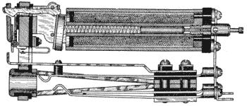
Code Signaling. On bridging party lines, where the subscribers sometimes call other subscribers on the same line and sometimes call the switchboard so as to obtain a connection with another line, it is not always easy for the operator at the switchboard to distinguish whether the call is for her or for some other party on the line. On such lines, of course, code ringing is used and in most cases the operator's only way of distinguishing between calls for her and those for some sub-station parties on the line is by listening to the rattling noise which the drop armature makes. In the case of the Monarch drop the adjustable spring tension on the armature is intended to provide for such an adjustment as will permit the armature to give a satisfactory buzz in response to the alternating ringing currents, whether the line be long or short.
Fig. 260. Code Signal Attachment View full size illustration.
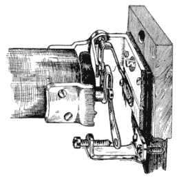
The Monarch Company provides in another way for code signaling at the switchboard. In some cases there is a special attachment, shown in Fig. 260, by means of which the code signals are repeated on the night-alarm bell. This is in the nature of a special attachment placed on the drop, which consists of a light, flat spring attached to the armature and forming one side of a local circuit. The other side of the circuit terminates in a fixture which is mounted on the drop frame and is provided with a screw, having a platinum point forming the other contact point; this allows of considerable adjustment. At the point where the screw comes in contact with the spring there is a platinum rivet. When an operator is not always in attendance, this code-signaling attachment has some advantages over the drop as a signal interpreter, in that it permits the code signals to be heard from a distance. Of course, the addition of spring contacts to the drop armature tends to complicate the structure and perhaps to cut down the sensitiveness of the drop, which are offsetting disadvantages.
Fig. 261. Combined Drop and Ringer View full size illustration.
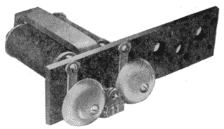
For really long lines, this code signaling by means of the drop is best provided for by employing a combined drop and ringer, although in this case whatever advantages are secured by the mechanical restoration of the shutter upon plugging in are lost. Such a device as manufactured by the Dean Electric Company is shown in Fig. 261. In this the ordinary polarized ringer is used, but in addition the tapper rod carries a latch which, when vibrated by the ringing of the bell, releases a shutter and causes it to fall, thus giving a visual as well as an audible signal.
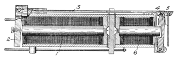
Electrical. Coming now to the electrical restoration of drop shutters, reference is made to Fig. 262, which shows in side section the electrical restoring drop employed by the Bell companies and manufactured by the Western Electric Company. In this the coil 1 is a line coil, and it operates on the armature 2 to raise the latch lever 3 in just the same manner as in the ordinary tubular drop. The latch lever 3 acts, however, to release another armature 4 instead of a shutter. This armature 4 is pivoted at its lower end at the opposite end of the device from the armature 2 and, by falling outwardly when released, it serves to raise the light shutter 5. The restoring coil of this device is shown at 6, and when energized it attracts the armature 4 so as to pull it back under the catch of the latch lever 3 and also so as to allow the shutter 5 to fall into its normal position. The method of closing the restoring circuit is by placing coil 6 in circuit with a local battery and with a pair of contacts in the jack, which latter contacts are normally open but are bridged across by the plug when it enters the jack, thus energizing the restoring coil and restoring the shutter.
Fig. 262. Electrically Restored Drop View full size illustration.
A perspective view of this Western Electric electrical restoring drop is shown in Fig. 263, a more complete mention being made of this feature under the discussion of magneto multiple switchboards, wherein it found its chief use. It is mentioned here to round out the methods that have been employed for accomplishing the automatic restoration of shutters by the insertion of the plug.
Fig. 263. Electrically Restored Drop View full size illustration.
Switchboard Plugs. A switchboard plug such as is commonly used in simple magneto switchboards is shown in Fig. 264 and also in Fig. 235. The tip contact is usually of brass and is connected to a slender steel rod which runs through the center of the plug and terminates near the rear end of the plug in a connector for the tip conductor of the cord. This central core of steel is carefully insulated from the outer shell of the plug by means of hard rubber bushings, the parts being forced tightly together. The outer shell, of course, forms the other conductor of the plug, called the sleeve contact. A handle of tough fiber tubing is fitted over the rear end of the plug and this also serves to close the opening formed by cutting away a portion of the plug shell, thus exposing the connector for the tip conductor.
Fig. 264. Switchboard Plug View full size illustration.
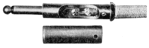
Cord Attachment. The rear end of the plug shell is usually bored out just about the size of the outer covering of the switchboard cord, and it is provided with a coarse internal screw thread, as shown. The cord is attached by screwing it tightly into this screw-threaded chamber, the screw threads in the brass being sufficiently coarse and of sufficiently small internal diameter to afford a very secure mechanical connection between the outer braiding of the cord and the plug. The connection between the tip conductor of the cord and the tip of the plug is made by a small machine screw connection as shown, while the connection between the sleeve conductor of the plug and the sleeve conductor of the cord is made by bending back the latter over the outer braiding of the cord before it is screwed into the shank of the plug. This results in the close electrical contact between the sleeve conductor of the cord and the inner metal surface of the shank of the plug.
Switchboard Cords. A great deal of ingenuity has been exerted toward the end of producing a reliable and durable switchboard cord. While great improvement has resulted, the fact remains that the cords of manual switchboards are today probably the most troublesome element, and they need constant attention and repairs. While no two manufacturers build their cords exactly alike, descriptions of a few commonly used and successful cords may be here given.
Concentric Conductors. In one the core is made from a double strand of strong lock stitch twine, over which is placed a linen braid. Then the tip conductor, which is of stranded copper tinsel, is braided on. This is then covered with two layers of tussah silk, laid in reverse wrappings, then there is a heavy cotton braid, and over the latter a linen braid. The sleeve conductor, which is also of copper tinsel, is then braided over the structure so formed, after which two reverse wrappings of tussah silk are served on, and this is covered by a cotton braid and this in turn by a heavy linen or polished cotton braid. The plug end of the cord is reinforced for a length of from 12 to 18 inches by another braiding of linen or polished cotton, and the whole cord is treated with melted beeswax to make it moisture-proof and durable.
Fig. 265. Switchboard Cord View full size illustration.

Steel Spiral Conductors. In another cord that has found much favor the two conductors are formed mainly by two concentric spiral wrappings of steel wire, the conductivity being reinforced by adjacent braidings of tinsel. The structure of such a cord is well shown in Fig. 265. Beginning at the right, the different elements shown are, in the order named, a strand of lock stitch twine, a linen braiding, into the strands of which are intermingled tinsel strands, the inner spiral steel wrapping, a braiding of tussah silk, a linen braiding, a loose tinsel braiding, the outer conductor of round spiral steel, a cotton braid, and an outside linen or polished cotton braid. The inner tinsel braiding and the inner spiral together form the tip conductor while the outer braiding and spiral together form the sleeve conductor. The cord is reinforced at the plug end for a length of about 14 inches by another braiding of linen. The tinsel used is, in each case, for the purpose of cutting down the resistance of the main steel conductor. These wrappings of steel wire forming the tip and sleeve conductors respectively, have the advantage of affording great flexibility, and also of making it certain that whatever strain the cord is subjected to will fall on the insulated braiding rather than on the spiral steel which has in itself no power to resist tensile strains.
Parallel Tinsel Conductors. Another standard two-conductor switchboard cord is manufactured as follows: One conductor is of very heavy copper tinsel insulated with one wrapping of sea island cotton, which prevents broken ends of the tinsel or knots from piercing through and short-circuiting with the other conductor. Over this is placed one braid of tussah silk and an outer braid of cotton. This combines high insulation with considerable strength. The other conductor is of copper tinsel, not insulated, and this is laid parallel to the thrice insulated conductor already described. Around these two conductors is placed an armor of spring brass wire in spiral form, and over this a close, stout braid of glazed cotton. This like the others is reinforced by an extra braid at the plug end.
Ringing and Listening Keys. The general principles of the ringing key have already been referred to. Ringing keys are of two general types, one having horizontal springs and the other vertical.
Fig. 266. Horizontal-Spring Listening and Ringing Key View full size illustration.
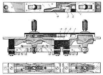
Horizontal Spring Type. Various Bell operating companies have generally adhered to the horizontal spring type except in individual and four-party-line keys. The construction of a Western Electric Company horizontal spring key is shown in Fig. 266. In this particular key, as illustrated, there are two cam levers operating upon three sets of springs. The cam lever at the left operates the ordinary ringing and listening set of springs according to whether it is pushed one way or the other. In ringing on single-party lines the cam lever at the left is the one to be used; while on two-party lines the lever at the left serves to ring the first party and the ringing key at the right the second party.
In order that the operator may have an indication as to which station on a two-party line she has called, a small target 1 carried on a lever 2 is provided. This target may display a black or a white field, according to which of its positions it occupies. The lever 2 is connected by the links 3 and 4 with the two key levers and the target is thus moved into one position or the other, according to which lever was last thrown into ringing position.
It will be noticed that the springs are mounted horizontally and on edge. This on-edge feature has the advantage of permitting ready inspection of the contacts and of avoiding the liability of dust gathering between the contacts. As will be seen, at the lower end of each switch lever there is a roller of insulating material which serves as a wedge, when forced between the two long springs of any set, to force them apart and into engagement with their respective outer springs.
Fig. 267. Vertical-Spring Listening and Ringing Key View full size illustration.
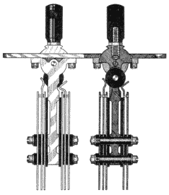
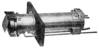
Vertical Spring Type. The other type of ringing and listening key employing vertical springs is almost universally used by the various independent manufacturing companies. A good example of this is shown in Fig. 267, which shows partly in elevation and partly in section a double key of the Monarch Company. The operation of this is obvious from its mode of construction. The right-hand set of springs of the right-hand key in this cut are the springs of the listening key, while the left-hand set of the right-hand key are those of the calling-plug ringing key. The left-hand set of the left-hand key may be those of a ring-back key on the answering plug, while the right-hand set of the left-hand key may be for any special purpose. It is obvious that these groups of springs may be grouped in different combinations or omitted in part, as required. This same general form of key is also manufactured by the Kellogg Company and the Dean Company, that of the Kellogg Company being illustrated in perspective, Fig. 268. The keys of this general type have the same advantages as those of the horizontal on-edge arrangement with respect to the gathering of dust, and while perhaps the contacts are not so readily get-at-able for inspection, yet they have the advantage of being somewhat more simple, and of taking up less horizontal space on the key shelf.
Fig. 268. Vertical Listening and Ringing Key View full size illustration.
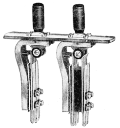
Fig. 269. Four-Party Listening and Ringing Key View full size illustration.
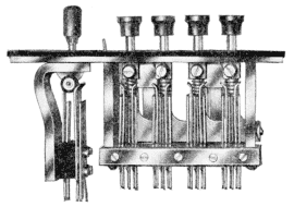
Party-Line Ringing Keys. For party-line ringing the key matter becomes somewhat more complicated. Usually the arrangement is such that in connection with each calling plug there are a number of keys, each arranged with respect to the circuits of the plug so as to send out the proper combination and direction of current, if the polarity system is used; or the proper frequency of current if the harmonic system is used; or the proper number of impulses if the step-by-step or broken-line system is used. The number of different kinds of arrangements and combinations is legion, and we will here illustrate only an example of a four-party line ringing key adapted for harmonic ringing. A Kellogg party-line listening and ringing key is shown in Fig. 269. In this, besides the regular listening key, are shown four push-button keys, each adapted, when depressed, to break the connection back of the key, and at the same time connect the proper calling generator with the calling plug.
Self-Indicating Keys. A complication that has given a good deal of trouble in the matter of party-line ringing is due to the fact that it is sometimes necessary to ring a second or a third time on a party-line connection, because the party called may not respond the first time. The operator is not always able to remember which one of the four keys associated with the plug connected with the desired party she has pressed on the first occasion and, therefore, when it becomes necessary to ring again, she may ring the wrong party. This is provided for in a very ingenious way in the key shown in Fig. 269, by making the arrangement such that after a given key has been depressed to its full extent in ringing, and then released, it does not come quite back to its normal position but remains slightly depressed. This always serves as an indication to the operator, therefore, as to which key she depressed last, and in the case of a re-ring, she merely presses the key that is already down a little way. On the next call if she is required to press another one of the four keys, the one which remained down a slight distance on the last call will be released and the one that is fully depressed will be the one that remains down as an indication.
Such keys, where the key that was last used leaves an indication to that effect, are called indicating ringing keys. In other forms the indication is given by causing the key lever to move a little target which remains exposed until some other key in the same set is moved. The key shown in Fig. 266 is an example of this type.
NOTE. The matter of automatic ringing and other special forms of ringing will be referred to and discussed at their proper places in this work, but at this point they are not pertinent as they are not employed in simple switchboards.
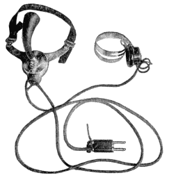
Operator's Telephone Equipment. Little need be said concerning the matter of the operator's talking apparatus, i.e., the operator's transmitter and receiver, since as transmitters and receivers they are practically the same as those in ordinary use for other purposes. The watch-case receiver is nearly always employed for operators' purposes on account of its lightness and compactness. It is used in connection with a head band so as to be held continually at the operator's ear, allowing both of her hands to be free.
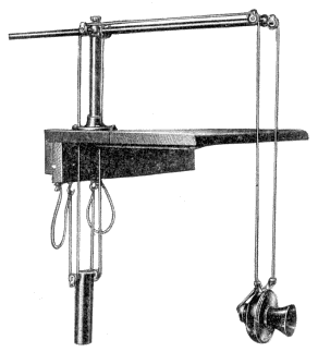
The transmitter used by operators does not in itself differ from the transmitters employed by subscribers, but the methods by which it is supported differ, two general practices being followed. One of these is to suspend the transmitter by flexible conducting cords so as to be adjustable in a vertical direction. A good illustration of this is given in Fig. 270. The other method, and one that is coming into more and more favor, is to mount the transmitter on a light bracket suspended by a flexible band from the neck of the operator, a breast plate being furnished so that the transmitter will rest on her breast and be at all times within proper position to receive her speech. To facilitate this, a long curved mouthpiece is commonly employed, as shown clearly in Fig. 47.
Fig. 270. Operator's Transmitter Suspension View full size illustration.
Cut-in Jack. It is common to terminate that portion of the apparatus which is worn on the operator's person—that is, the receiver only if the suspended type of transmitter is employed, and the receiver and transmitter if the breast plate type of transmitter is employed—in a plug, and a flexible cord connecting the plug terminates with the apparatus. The portions of the operator's talking circuit that are located permanently in the switchboard cabinet are in such cases terminated in a jack, called an operator's cut-in jack. This is usually mounted on the front rail of the switchboard cabinet just below the key shelf. Such a cut-in jack is shown in Fig. 271 and it is merely a specialized form of spring jack adapted to receive the short, stout plug in which the operator's transmitter, or transmitter and receiver, terminate. By this arrangement the operator is enabled readily to connect or disconnect her talking apparatus, which is worn on her person, whenever she comes to the board for work or leaves it at the end of her work. A complete operator's telephone set, or that portion that is carried on the person of the operator, together with the cut-in plug, is shown in Fig. 272.
Fig. 271. Operator's Cut-in Jack View full size illustration.
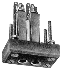
Fig. 272. Operator's Talking Set View full size illustration.
Circuits of Complete Switchboard. We may now discuss the circuits of a complete simple magneto switchboard. The one shown in Fig. 273 is typical. Before going into the details of this, it is well to inform the student that this general form of circuit representation is one that is commonly employed in showing the complete circuits of any switchboard. Ordinarily two subscribers' lines are shown, these connecting their respective subscribers' stations with two different line equipments at the central office. The jacks and signals of these line equipments are turned around so as to face each other, in order to clearly represent how the connection between them may be made by means of the cord circuit. The elements of the cord circuit are also spread out, so that the various parts occupy relative positions which they do not assume at all in practice. In other words it must be remembered that, in circuit diagrams, the relative positions of the parts are sacrificed in order to make clear the circuit connections. However, this does not mean that it is often not possible to so locate the pieces of apparatus that they will in a certain way indicate relative positions, as may be seen in the case of the drop and jack in Fig. 273, the drop being shown immediately above the jack, which is the position in which these parts are located in practice.
Fig. 273. Circuit of Simple Magneto Switchboard View full size illustration.
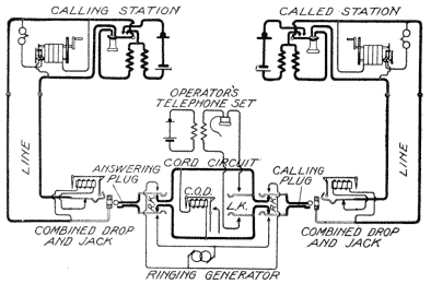
Little need be said concerning this circuit in view of what has already been said in connection with Figs. 240 to 245. It will be seen in the particular sub-station circuit here represented, that the talking apparatus is arranged in the usual manner and that the ringer and generator are so arranged that when the generator is operated the ringer will be cut out of circuit, while the generator will be placed across the circuit; while, when the generator is idle, the ringer is bridged across the circuit and the generator is cut out.
The line terminates in each case in the tip and sleeve contacts of the jack, and in the normal condition of the jack the line drop is bridged across the line. The arrangement by which the drop is restored and at the same time cut out of circuit when the operator plugs in the jack, is obvious from the diagrammatic illustration. The cord circuit is the same as that already discussed, with the exception that two ringing keys are provided, one in connection with the calling plug, as is universal practice, and the other in connection with the answering plug as is sometimes practiced in order that the operator may, when occasion requires, ring back the calling subscriber without the necessity of changing the plug in the jack. The outer contacts of these two ringing keys are connected to the terminals of the ringing generator and, when either key is operated, the connection between the plug, on which the ringing is to be done, and the rest of the cord circuit will be broken, while the generator will be connected with the terminals of the plug. The listening key and talking apparatus need no further explanation, it being obvious that when the key is operated the subscriber's telephone set will be bridged across the cord circuit and, therefore, connected with either or both of the talking subscribers.
Fig. 274. Night-Alarm Circuit View full size illustration.
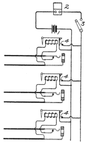
Night-Alarm Circuits. The circuit of Fig. 273, while referred to as a complete circuit, is not quite that. The night-alarm circuit is not shown. In order to clearly indicate how a single battery and bell, or buzzer, may serve in connecting a number of line drops, reference is made to Fig. 274 which shows the connection between three different line drops and the night-alarm circuit. The night-alarm apparatus consists in the battery 1 and the buzzer, or bell, 2. A switch 3 adapted to be manually operated is connected in the circuit with the battery and the buzzer so as to open this circuit when the night alarm is not needed, thus making it inoperative. During the portions of the day when the operator is needed constantly at the board it is customary to leave this switch 3 open, but during the night period when she is not required constantly at the board this switch is closed so that an audible signal will be given whenever a drop falls. The night-alarm contact 4 on each of the drops will be closed whenever a shutter falls, and as the two members of this contact, in the case of each drop, are connected respectively with the two sides of the night-alarm circuit, any one shutter falling will complete the necessary conditions for causing the buzzer to sound, assuming of course that the switch 3 is closed.
Night Alarm with Relay. A good deal of trouble has been caused in the past by uncertainty in the closure of the night-alarm circuit at the drop contact. Some of the companies have employed the form of circuit shown in Fig. 275 to overcome this. Instead of the night-alarm buzzer being placed directly in the circuit that is closed by the drop, a relay 5 and a high-voltage battery 6 are placed in this circuit. The buzzer and the battery for operating it are placed in a local circuit controlled by this relay. It will be seen by reference to Fig. 275 that when the shutter falls, it will, by closing the contact 4, complete the circuit from the battery 6 through the relay 5—assuming switch 3 to be closed—and thus cause the operation of the relay. The relay, in turn, by pulling up its armature, will close the circuit of the buzzer 2 through the battery 7 and cause the buzzer to sound.
Fig. 275. Night-Alarm Circuit with Relay View full size illustration.
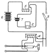
The advantage of this method over the direct method of operating the buzzer is that any imperfection in the night-alarm contact at the drop is much less likely to prevent the flow of current of the high-voltage battery 6 than of the low-voltage battery 1, shown in connection with Fig. 274. This is because the higher voltage is much more likely to break down any very thin bit of insulation, such as might be caused by a minute particle of dust or oxide between contacts that are supposed to be closed by the falling of the shutter. It has been common to employ for battery 6 a dry-cell battery giving about 20 or 24 volts, and for the operation of the buzzer itself, a similar battery of about two cells giving approximately 3 volts.
Night-Alarm Contacts. The night-alarm contact 4 of the drop shown diagrammatically in Figs. 274 and 275 would, if taken literally, indicate that the shutter itself actually forms one terminal of the circuit and the contact against which it falls, the other. This has not been found to be a reliable way of closing the night-alarm contacts and this method is indicated in these figures and in other figures in this work merely as a convenient way of representing the matter diagrammatically. As a matter of fact the night-alarm contacts are ordinarily closed by having the shutter fall against one spring, which is thereby pressed into engagement with another spring or contact, as shown in Fig. 249. This method employs the shutter only as a means for mechanically causing the one spring to press against the other, the shutter itself forming no part of the circuit. The reason why it is not a good plan to have the shutter itself act as one terminal of the circuit is that this necessitates the circuit connections being led to the shutter through the trunnions on which the shutter is pivoted. This is bad because, obviously, the shutter must be loosely supported on its trunnions in order to give it sufficiently free movement, and, as is well known, loose connections are not conducive to good electrical contacts.
Grounded-and Metallic-Circuit Lines. When grounded circuits were the rule rather than the exception, many of the switchboards were particularly adapted for their use and could not be used with metallic-circuit lines. These grounded-circuit switchboards provided but a single contact in the jack and a single contact on the plug, the cords having but a single strand reaching from one plug to the other. The ringing keys and listening keys were likewise single-contact keys rather than double. The clearing-out drop and the operator's talking circuit and the ringing generator were connected between the single strand of the cord and the ground as was required.
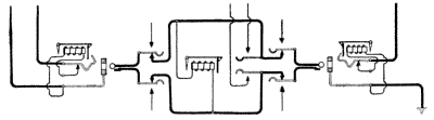
The grounded-circuit switchboard has practically passed out of existence, and while a few of them may be in use, they are not manufactured at present. The reason for this is that while many grounded circuits are still in use, there are very few places where there are not some metallic-circuit lines, and while the grounded-circuit switchboard will not serve for metallic-circuit lines, the metallic-circuit switchboard will serve equally well for either metallic-circuit or grounded lines, and will interconnect them with equal facility. This fact will be made clear by a consideration of Figs. 276, 277, and 278.
Fig. 276. Connection Between Metallic Lines View full size illustration.
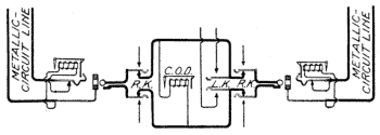
Fig. 277. Connection Between Grounded Lines View full size illustration.
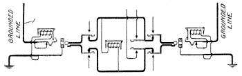
Connection between Two Similar Lines. In Fig. 276 a common magneto cord circuit is shown connecting two metallic-circuit lines; in Fig. 277 the same cord circuit is shown connecting two grounded lines. In this case the line wire 1 of the left-hand line is, when the plugs are inserted, continued to the tip of the answering plug, thence through the tip strand of the cord circuit to the tip of the calling plug, then to the tip spring of the right-hand jack and out to the single conductor of that line. The entire sleeve portion of the cord circuit becomes grounded as soon as the plugs are inserted in the jacks of such a line. Hence, we see that the sleeve contacts of the plug and the sleeve conductor of the cord are connected to ground through the permanent ground connection of the sleeve conductors of the jack as soon as the plug is inserted into the jack. Thus, when the cord circuit of a metallic-circuit switchboard is used to connect two grounded circuits together, the tip strand of the cord is the connecting link between the two conductors, while the sleeve strand of the cord merely serves to ground one side of the clearing-out drop and one side each of the operator's telephone set and the ringing generator when their respective keys are operated.
Connection between Dissimilar Lines. Fig. 278 shows how the same cord circuit and the same arrangement of line equipment may be used for connecting a grounded line to a metallic-circuit line. The metallic circuit line is shown on the left and the grounded line on the right. When the two plugs are inserted into the respective jacks of this figure, the right-hand conductor of the metallic circuit shown on the left will be continued through the tip strand of the cord circuit to the line conductor of the grounded line shown on the right. The left-hand conductor of the metallic-circuit line will be connected to ground because it will be continued through the sleeve strand of the cord circuit to the sleeve contact of the calling plug and thence to the sleeve contact of the jack of the grounded line, which sleeve contact is shown to be grounded. The talking circuit between the two connected lines in this case may be traced as follows: From the subscriber's station at the left through the right-hand limb of the metallic-circuit line, through the tip contact and tip conductor of the cord circuit, to the single limb of the grounded-circuit line, thence to the sub-station of that line and through the talking apparatus there to ground. The return path from the right-hand station is by way of ground to the ground connection at the central office, thence to the sleeve contact of the grounded line jack, through the sleeve conductor of the cord circuit, to the sleeve contact of the metallic-circuit line jack, and thence by the left-hand limb of the metallic-circuit line to the subscriber's station.
Fig. 278. Connection Between Dissimilar Lines View full size illustration.
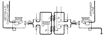
A better way of connecting a metallic-circuit line to a grounded line is by the use of a special cord circuit involving a repeating coil, such a connection being shown in Fig. 279. The cord circuit in this case differs in no respect from those already shown except that a repeating coil is associated with it in such a way as to conductively divide the answering side from the calling side. Obviously, whatever currents come over the line connected with the answering plug will pass through the windings 1 and 2 of this coil and will induce corresponding currents in the windings 3 and 4, which latter currents will pass out over the circuit of the line connected with the calling plug. When a grounded circuit is connected to a metallic circuit in this manner, no ground is thrown onto the metallic circuit. The balance of the metallic circuit is, therefore, maintained.
To ground one side of a metallic circuit frequently so unbalances it as to cause it to become noisy, that is, to have currents flowing in it, by induction or from other causes, other than the currents which are supposed to be there for the purpose of conveying speech.
Fig. 279. Connection of Dissimilar Lines through Repeating Coil View full size illustration.
Convertible Cord Circuits. The consideration of Fig. 279 brings us to the subject of so-called convertible cord circuits. Some switchboards, serving a mixture of metallic and grounded lines, are provided with cord circuits which may be converted at will by the operator from the ordinary type shown in Fig. 276 to the type shown in Fig. 279. The advantage of this will be obvious from the following consideration. When a call originates on any line, either grounded or metallic, the operator does not know which kind of a line is to be called for. She, therefore, plugs into this line with any one of her answering plugs and completes the connection in the usual way. If the call is for the same kind of a circuit as that over which the call originated, she places the converting key in such a position as will connect the conductors of the cord circuit straight through; while if the connection is for a different kind of a line than that on which the call originated she throws the converting key into such a position as to include the repeating coil. A study of Fig. 280 will show that when the converting key, which is commonly referred to as the repeating-coil key, is in one position, the cord conductors will be cut straight through, the repeating coil being left open in both its windings; and when it is thrown to its other position, the connection between the answering and calling sides of the cord circuit will be severed and the repeating coil inserted so as to bring about the same effects and circuit arrangements as are shown in Fig. 279.
Fig. 280. Convertible Cord Circuit View full size illustration.
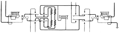
Cord-Circuit Considerations. Simple Bridging Drop Type. The matter of cord circuits in magneto switchboards is deserving of much attention. So far as talking requirements are concerned, the ordinary form of cord circuit with a clearing-out drop bridged across the two strands is adequate for nearly all conditions except those where a grounded-and a metallic-circuit line are connected together, in which case the inclusion of a repeating coil has some advantages.
Fig. 281. Bridging Drop-Cord Circuit View full size illustration.
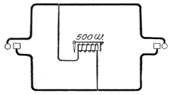
From the standpoint of signaling, however, this type of cord circuit has some disadvantages under certain conditions. In order to simplify the discussion of this and other cord-circuit matters, reference will be made to some diagrams from which the ringing and listening keys and talking apparatus have been entirely omitted. In Fig. 281 the regular bridging type of clearing-out drop-cord circuit is shown, this being the type already discussed as standard. For ordinary practice it is all right. Certain difficulties are experienced with it, however, where lines of various lengths and various types of sub-station apparatus are connected. For instance, if a long bridging line be connected with one end of this cord circuit and a short line having a low-resistance series ringer be connected with the other end, then a station on the long line may have some difficulty in throwing the clearing-out drop, because of the low-resistance shunt that is placed around it through the short line and the low-resistance ringer. In other words, the clearing-out drop is shunted by a comparatively low-resistance line and ringer and the feeble currents arriving from a distant station over the long line are not sufficient to operate the drop thus handicapped. The advent of the various forms of party-line selective signaling and the use of such systems in connection with magneto switchboards has brought in another difficulty that sometimes manifests itself with this type of cord circuit. If two ordinary magneto telephones are connected to the two ends of this cord circuit, it is obvious that when one of the subscribers has hung up his receiver and the other subscriber rings off, the bell of the other subscriber will very likely be rung even though the clearing-out drop operates properly; it would be better in any event not to have this other subscriber's bell rung, for he may understand it to be a recall to his telephone. When, however, a party line is connected through such a cord circuit to an ordinary line having bridging instruments, for instance, the difficulty due to ringing off becomes even greater. When the subscriber on the magneto line operates his generator to give the clearing-out signal, he is very likely to ring some of the bells on the other line and this, of course, is an undesirable thing. This may happen even in the case of harmonic bells on the party line, since it is possible that the subscriber on the magneto line in turning his generator will, at some phase of the operation, strike just the proper frequency to ring some one of the bells on the harmonic party line. It is obvious, therefore, that there is a real need for a cord circuit that will prevent through ringing.
One way of eliminating the through-ringing difficulty in the type of cord circuit shown in Fig. 281 would be to use such a very low-wound clearing-out drop that it would practically short-circuit the line with respect to ringing currents and prevent them from passing on to the other line. This, however, is not a good thing to do, since a winding sufficiently low to shunt the effective ringing current would also be too low for good telephone transmission.
Fig. 282. Series Drop-Cord Circuit View full size illustration.
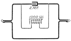
Series Drop Type. Another type of cord circuit that was largely used by the Stromberg-Carlson Telephone Manufacturing Company at one time is shown in Fig. 282. In this the clearing-out drop was not bridged but was placed in series in the tip side of the line and was shunted by a condenser. The resistance of the clearing-out drop was 1,000 ohms and the capacity of the condenser was 2 microfarads. It is obvious that this way of connecting the clearing-out drop was subject to the ringing-through difficulty, since the circuit through which the clearing-out current necessarily passed included the telephone instrument of the line that was not sending the clearing-out signal. This form was also objectionable because it was necessary for the subscriber to ring through the combined resistance of two lines, and in case the other line happened to be open, no clearing-out signal would be received. While this circuit, therefore, was perhaps not quite so likely as the other to tie up the subscriber, that is, to leave him connected without the ability to send a clearing-out signal, yet it was sure to ring through, for the clearing-out drop could not be thrown without the current passing through the other subscriber's station.
Fig. 283. Dean Non-Ring-Through Cord Circuit View full size illustration.
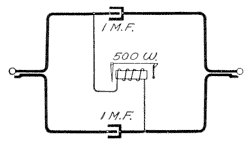
Non-Ring-Through Type. An early attempt at a non-ring-through cord is shown in Fig. 283, this having once been standard with the Dean Electric Company. It made use of two condensers of 1 microfarad each, one in each side of the cord circuit. The clearing-out drop was of 500 ohms resistance and was connected from the answering side of the tip conductor to the calling side of the sleeve conductor. In this way whatever clearing-out current reached the central office passed through at least one of the condensers and the clearing-out drop. In order for the clearing-out current to pass on beyond the central office it was necessary for it to pass through the two condensers in series. This arrangement had the advantage of giving a positive ring-off, regardless of the condition of the connected line. Obviously, even if the line was short-circuited, the ringing currents from the other line would still be forced through the clearing-out drop on account of the high effective resistance of the 1-microfarad condenser connected in series with the short-circuited line. Also the clearing-out signal would be properly received if the connected line were open, since the clearing-out drop would still be directly across the cord circuit. This arrangement also largely prevented through ringing, since the currents would pass through the 1-microfarad condenser and the 500-ohm drop more readily than through the two condensers connected in series.
Fig. 284. Monarch Non-Ring-Through Cord Circuit View full size illustration.
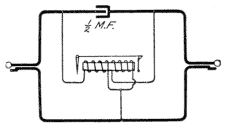
In Fig. 284 is shown the non-ring-through arrangement of cord circuit adopted by the Monarch Company. In this system the clearing-out drop has two windings, either of which will operate the armature. The two windings are bridged across the cord circuit, with a 1/2-microfarad condenser in series in the tip strand between the two winding connections. While the low-capacity condenser will allow the high-frequency talking current to pass readily without affecting it to any appreciable extent, it offers a high resistance to a low-frequency ringing current, thus preventing it from passing out on a connected line and forcing it through one of the windings of the coil. There is a tendency to transformer action in this arrangement, one of the windings serving as a primary and the other as a secondary, but this has not prevented the device from being highly successful.
A modification of this arrangement is shown in Fig. 285, wherein a double-wound clearing-out drop is used, and a 1/2-microfarad condenser is placed in series in each side of the cord circuit between the winding connections of the clearing-out drop. This circuit should give a positive ring-off under all conditions and should prevent through ringing except as it may be provided by the transformer action between the two windings on the same core.
Fig. 285. Non-Ring-Through Cord Circuit View full size illustration.
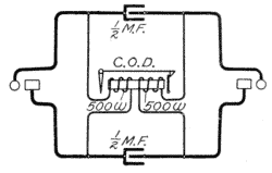
Another rather ingenious method of securing a positive ring-off and yet of preventing in a certain degree the undesirable ringing-through feature is shown in the cord circuit, Fig. 286. In this two non-inductive coils 1 and 2 are shown connected in series in the tip and sleeve strands of the coils, respectively. Between the neutral point of these two non-inductive windings is connected the clearing-out drop circuit. Voice currents find ready path through these non-inductive windings because of the fact that, being non-inductive, they present only their straight ohmic resistance. The impedance of the clearing-out drop prevents the windings being shunted across the two sides of the cord circuit. With this circuit a positive ring-off is assured even though the line connected with the one sending the clearing-out signal is short-circuited or open. If it is short-circuited, the shunt around the clearing-out drop will still have the resistance of two of the non-inductive windings included in it, and thus the drop will never be short-circuited by a very low-resistance path. Obviously, an open circuit in the line will not prevent the clearing-out signal being received. While this is an ingenious scheme, it is not one to be highly recommended since the non-inductive windings, in order to be effective so far as signaling is concerned, must be of considerable resistance and this resistance is in series in the talking circuit. Even non-inductive resistance is to be avoided in the talking circuit when it is of considerable magnitude and where there are other ways of solving the problem.
Fig. 286. Cord Circuit with Differential Windings View full size illustration.
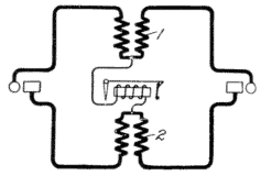
Double Clearing-out Type. Some people prefer two clearing-out drops in each cord circuit, so arranged that the one will be responsive to currents sent from the line with which the answering plug is connected and the other responsive only to currents sent from the line with which the calling plug is connected. Such a scheme, shown in Fig. 287, is sometimes employed by the Dean, the Monarch, and the Kellogg companies. Two 500-ohm clearing-out drops of ordinary construction are bridged across the cord circuit and in each side of the cord circuit there is included between the drop connections a 1-microfarad condenser. Ringing currents originating on the line with which the answering plug is connected will pass through the clearing-out drop, which is across that side of the cord circuit, without having to pass through any condensers. In order to reach the other clearing-out drop the ringing current must pass through the two 1-microfarad condensers in series, this making in effect only 1/2-microfarad. As is well known, a 1/2-microfarad condenser not only transmits voice currents with ease but also offers a very high apparent resistance to ringing currents. With the double clearing-out drop system the operator is enabled to tell which subscriber is ringing off. If both shutters fall she knows that both subscribers have sent clearing-out signals and she, therefore, pulls down the connection without the usual precaution of listening to see whether one of the subscribers may be waiting for another connection. This double clearing-out system is analogous to the complete double-lamp supervision that will be referred to more fully in connection with common-battery circuits. There is not the need for double supervision in magneto work, however, that there is in common-battery work because of the fact that in magneto work the subscribers frequently fail to remember to ring off, this act being entirely voluntary on their part, while in common-battery work, the clearing-out signal is given automatically by the subscriber when he hangs up his receiver, thus accomplishing the desired end without the necessity of thoughtfulness on his part.
Fig. 287. Double Clearing-Out Drops View full size illustration.
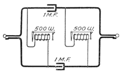
Another form of double clearing-out cord circuit is shown in Fig. 288. In this the calling and the answering plugs are separated by repeating coils, a condenser of 1-microfarad capacity being inserted between each pair of windings on the two ends of the circuit. The clearing-out drops are placed across the calling and answering cords in the usual manner. The condenser in this case prevents the drop being short-circuited with respect to ringing currents and yet permits the voice currents to flow readily through it. The high impedance of the drop forces the voice currents to take the path through the repeating coil rather than through the drop. This circuit has the advantage of a repeating-coil cord circuit in permitting the connection of metallic and grounded lines without causing the unbalancing of the metallic circuits by the connection to them of the grounded circuits.
Fig. 288. Double Clearing-Out Drops View full size illustration.
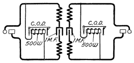
Recently there has been a growing tendency on the part of some manufacturers to control their clearing-out signals by means of relays associated with cord circuits, these signals sometimes being ordinary clearing-out drops and sometimes incandescent lamps.
Fig. 289. Relay-Controlled Clearing-Out Drop View full size illustration.
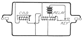
In Fig. 289 is shown the cord circuit sometimes used by the L.M. Ericsson Telephone Manufacturing Company. A high-wound relay is normally placed across the cord and this, besides having a high-resistance and impedance winding has a low-resistance locking winding so arranged that when the relay pulls up its armature it will close a local circuit including this locking winding and local battery. When once pulled up the relay will, therefore, stay up due to the energizing of this locking coil. Another contact operated by the relay closes the circuit of a low-wound clearing-out drop placed across the line, thus bridging it across the line. The condition of high impedance is maintained across the cord circuit normally while the subscribers are talking; but when either of them rings off, the high-wound relay pulls up and locks, thus completing the circuit of the clearing-out drop across the cords. The subsequent impulses sent from the subscribers' generators operate this drop. The relay is restored or unlocked and the clearing-out drop disconnected from the cord circuit by means of a key which opens the locking circuit of the relay. This key is really a part of the listening key and serves to open this locking circuit whenever the listening key is operated. The clearing-out drop is also automatically restored by the action of the listening key, this connection being mechanical rather than electrical.
Recall Lamp:—The Monarch Company sometimes furnishes what it terms a recall lamp in connection with the clearing-out drops on its magneto switchboards. The circuit arrangement is shown in Fig. 290, wherein the drop is the regular double-wound clearing-out drop like that of Fig. 284. The armature carries a contact spring adapted to close the local circuit of a lamp whenever it is attracted. The object of this is to give the subscriber, whose line still remains connected by a cord circuit, opportunity to recall the central office if the operator has not restored the clearing-out drop.
Fig. 290. Cord Circuit with Recall Lamp View full size illustration.
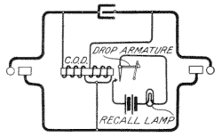
Lamp-Signal Type. There has been a tendency on the part of some manufacturing companies to advocate, instead of drop signals, incandescent lamp signals for the cord circuits, and sometimes for the line circuits on magneto boards. In most cases this may be looked upon as a "frill." Where line lamps instead of drops have been used on magneto switchboards, it has been the practice to employ, instead of a drop, a locking relay associated with each lamp, which was so arranged that when the relay was energized by the magneto current from the subscriber's station, it would pull up and lock, thus closing the lamp circuit.
The local circuit, or locking circuit, which included the lamp was carried through a pair of contacts in the corresponding jacks so arranged that when the plug was inserted in answer to the call, this locking lamp circuit would be open, thereby extinguishing the lamp and also unlocking the relay. There seems to be absolutely no good reason why lamp signals should be substituted for mechanical drops in magneto switchboards. There is no need for the economy in space which the lamp signal affords, and the complications brought in by the locking relays, and the requirements for maintaining a local battery suitable for energizing the lamps are not warranted for ordinary cases.
Fig. 291. Cord Circuit with Double Lamp Signals View full size illustration.
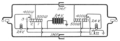
In Fig. 291 is shown a cord circuit, adaptable to magneto switchboards, provided with double lamp signals instead of clearing-out drops. Two high-wound locking relays are bridged across the line, the cord strands being divided by 1-microfarad condensers. When the high-wound coil of either relay is energized by the magneto current from the subscriber's station, the relay pulls up and closes a locking circuit including a battery and a coil 2, the contact 3 of the locking relay, and also the contact 4 of a restoring key. This circuit may be traced from the ground through battery, coil 2, contact 3 controlled by the relay, and contact 4 controlled by the restoring key, and back to ground. In multiple with the locking coil 2 is the lamp, which is illuminated, therefore, whenever the locking circuit is closed. Pressure on the restoring key breaks the locking circuit of either of the lamps, thereby putting out the lamp and at the same time restoring the locking relay to its normal position.
Lamps vs. Drops in Cord Circuits. So much has been said and written about the advantages of incandescent lamps as signals in switchboards and about the merits of the common-battery method of supplying current to the subscribers, that there has been a tendency for people in charge of the operation of small exchanges to substitute the lamp for the drop in a magneto switchboard in order to give the general appearance of common-battery operations. There has also been a tendency to employ the common-battery system of operation in many places where magneto service should have been used, a mistake which has now been realized and corrected. In places where the simple magneto switchboard is the thing to use, the simpler it is the better, and the employment of locking relays and lamp signals and the complications which they carry with them, is not warranted.