Volume 1 — CHAPTER XXI (continued 2)
Reading edition
Switchboard Assembly. The assembly of all the parts of a simple magneto switchboard into a complete whole deserves final consideration. The structure in which the various parts are mounted, referred to as the cabinet, is usually of wood.
Functions of Cabinet. The purpose of the cabinet is not only to form a support for the various pieces of apparatus but also to protect them from dust and mechanical injury, and to hold those parts that must be manipulated by the operator in such relation that they may be most convenient for use, and thus best adapted for carrying out their various functions. Other points to be provided for in the design of the cabinet and the arrangement of the various parts within are: that all the apparatus that is in any way liable to get out of order may be readily accessible for inspection and repairs; and that provision shall be made whereby the wiring of these various pieces of apparatus may be done in a systematic and simple way so as to minimize the danger of crossed, grounded, or open circuits, and so as to provide for ready repair in case any of these injuries do occur.
Wall-Type Switchboards. The simplest form of switchboard is that for serving small communities in rural districts. Ordinarily the telephone industry in such a community begins by a group of farmers along a certain road building a line connecting the houses of several of them and installing their own instruments. This line is liable to be extended to some store at the village or settlement, thus affording communication between these farmers and the center of their community. Later on those residing on other roads do the same thing and connect their lines to the same store or central point. Then it is that some form of switchboard is established, and perhaps the storekeeper's daughter or wife is paid a small fee for attendance.
Fig. 292. Wall Switchboard with Telephone View full size illustration.
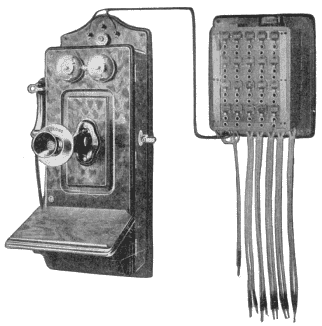
A switchboard well-adapted for this class of service where the number of lines is small, is shown in Fig. 292. In this the operator's talking apparatus and her calling apparatus are embodied in an ordinary magneto wall telephone. The switchboard proper is mounted alongside of this, and the two line binding posts of the telephone are connected by a pair of wires to terminals of the operator's plug, which plug is shown hanging from the left-hand portion of the switchboard. The various lines centering at this point terminate in the combined drops and jacks on the switchboard, of which there are 20 shown in this illustration. Beside the operator's plug there are a number of pairs of plugs shown hanging from the switchboard cabinet. These are connected straight through in pairs, there being no clearing-out drops or keys associated with them in the arrangement. Each line shown is provided with an extra jack, the purpose of which will be presently understood.
The method of operation is as follows: When a subscriber on a certain line desires to get connection through the switchboard he turns his generator and throws the drop. The operator in order to communicate with him inserts the plug in which her telephone terminates into the jack, and removes her receiver from its hook. Having learned that it is for a certain subscriber on another line, she withdraws her plug from the jack of the calling line and inserts it into the jack of the called line, then, hanging up her receiver, she turns the generator crank in accordance with the proper code to call that subscriber. When that subscriber responds she connects the two lines by inserting the two plugs of a pair into their respective jacks, and the subscribers are thus placed in communication. The extra jack associated with each line is merely an open jack having its terminals connected respectively with the two sides of the line. Whenever an operator desires to listen in on two connected lines she does so by inserting the operator's plug into one of these extra jacks of the connected lines, and she may thus find out whether the subscribers are through talking or whether either one of them desires another connection. The drops in such switchboards are commonly high wound and left permanently bridged across the line so as to serve as clearing-out drops. The usual night-alarm attachment is provided, the buzzer being shown at the upper right-hand portion of the cabinet.
Fig. 293. Combined Telephone and Switchboard View full size illustration.
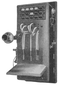
Another type of switchboard commonly employed for this kind of service is shown in Fig. 293, in which the telephone and the switchboard cabinet are combined. The operation of this board is practically the same as that of Fig. 292, although it has manually-restored drops instead of self-restoring drops; the difference between these two types, however, is not material for this class of service. For such work the operator has ample time to attend to the restoring of the drop and the only possible advantage in the combined drop-and-jack for this class of work is that it prevents the operator from forgetting to restore the drops. However, she is not likely to do this with the night-alarm circuit in operation, since the buzzer or bell would continue to ring as long as the drop was down.
Fig. 294. Upright Magneto Switchboard View full size illustration.
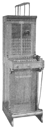
Fig. 295. Upright Magneto Switchboard—Rear View View full size illustration.
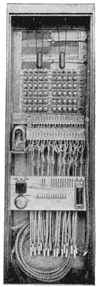
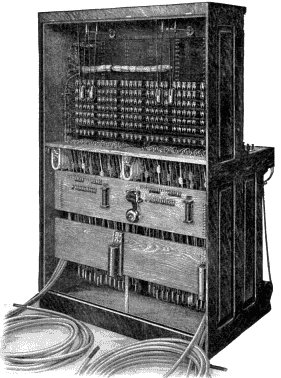
Upright Type Switchboard. By far the most common type of magneto switchboard is the so-called upright type, wherein the drops and jacks are mounted on the face of upright panels rising from a horizontal shelf, which shelf contains the plugs, the keys, and any other apparatus which the operator must manipulate. Front and rear views of such a switchboard, as manufactured by the Kellogg Company, are shown in Figs. 294 and 295. This particular board is provided with fifty combined drops and jacks and, therefore, equipped for fifty subscribers' lines. The drops and jacks are mounted in strips of five, and arranged in two panels. The clearing-out drops, of which there are ten, are arranged at the bottom of the two panels in a single row and may be seen immediately above the switchboard plugs. There are ten pairs of cords and plugs with their associated ringing and listening keys, the plugs being mounted on the rear portion of the shelf, while the ringing and listening keys are mounted on the hinged portion of the shelf in front of the plugs.
Fig. 296. Details of Drop, Jack, Plug, and Key Arrangement View full size illustration.
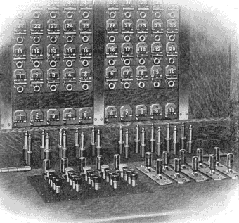
Fig. 297. Cross-Section of Upright Switchboard (partial) View full size illustration.
A better idea of the arrangement of drops, jacks, plugs, and keys may be had from an illustration of a Dean magneto switchboard shown in Fig. 296. The clearing-out drops and the arrangement of the plugs and keys are clearly shown. The portion of the switchboard on which the plugs are mounted is always immovable, the plugs being provided with seats through which holes are bored of sufficient size to permit the switchboard cord to pass beneath the shelf. When one of these plugs is raised, the cord is pulled up through this hole thus allowing the plug to be placed in any of the jacks.
The key arrangement shown in this particular cut is instructive. It will be noticed that the right-hand five pairs of plugs are provided with ordinary ringing and listening keys, while the left-hand five are provided with party-line ringing keys and listening keys. The listening key in each case is the one in the rear and is alike for all of the cord pairs. The right-hand five ringing keys are so arranged that pressing the lever to the rear will ring on the answering cord, while pressing it toward the front will cause ringing current to flow on the calling plug. In the left-hand five pairs of cords shown in this cut, the pressure of any one of the keys causes a ringing current of a certain frequency to flow on the calling cord, this frequency depending upon which one of the keys is pressed.
Fig. 298. Cord Weight View full size illustration.
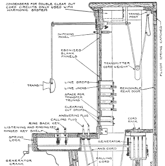
An excellent idea of the grouping of the various pieces of apparatus in a complete simple magneto switchboard may be had from Fig. 297. While the arrangement here shown is applicable particularly to the apparatus of the Dean Electric Company, the structure indicated is none-the-less generally instructive, since it represents good practice in this respect. In this drawing the stationary plug shelf with the plug seat is clearly shown and also the hinged key shelf. The hinge of the key shelf is an important feature and is universally found in all switchboards of this general type. The key shelf may be raised and thus expose all of the wiring leading to the keys, as well as the various contacts of the keys themselves, to inspection.
Fig. 299. Magneto Switchboard, Target Signals (partial) View full size illustration.
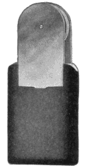
As will be seen, the switchboard cords leading from the plugs extend down to a point near the bottom of the cabinet where they pass through pulley weights and then up to a stationary cord rack. On this cord rack are provided terminals for the various conductors in the cord, and it is at this point that the cord conductors join the other wires leading to the other portions of the apparatus as required. A good form of cord weight is shown in Fig. 298; and obviously the function of these weights is to keep the cords taut at all times and to prevent their tangling.
Fig. 300. Rear View of Target Signal, Magneto Switchboard View full size illustration.
The drawing, Fig. 297, also gives a good idea of the method of mounting the hand generator that is ordinarily employed with such magneto switchboards. The shaft of the generator is merely continued out to the front of the key shelf where the usual crank is provided, by means of which the operator is able to generate the necessary ringing current. Beside the hand generator at each operator's position, it is quite common in magneto boards, of other than the smallest sizes, to employ some form of ringing generator, either a power-driven generator or a pole changer driven by battery current for furnishing ringing current without effort on the part of the operator.
Fig. 301. Dean Two-Position Switchboard View full size illustration.
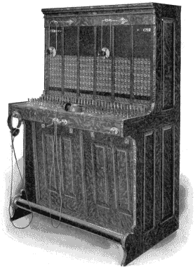
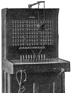
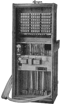
Switchboards as shown in Figs. 294 and 295, are called single-position switchboards because they afford room for a single operator. Ordinarily for this class of work a single operator may handle from one to two hundred lines, although of course this depends on the amount of traffic on the line, and this, in turn, depends on the character of the subscribers served, and also on the average number of stations on a line. Another single-position switchboard is shown in Figs. 299 and 300, being a front and rear view of the simple magneto switchboard of the Western Electric Company, which is provided with the target signals of that company rather than the usual form of drop.
Where a switchboard must accommodate more lines than can be handled by a single operator, the cabinet is made wider so as to afford room for more than one operator to be seated before it. Sometimes this is accomplished by building the cabinet wider, or by putting two such switchboard sections as are shown in Figs. 294 or 299 side by side. A two-position switchboard section is shown in front and rear views in Figs. 301 and 302.
Fig. 302. Rear View of Dean Two-Position Switchboard View full size illustration.
Sectional Switchboards. The problem of providing for growth in a switchboard is very much the same as that which confronts one in buying a bookcase for his library. The Western Electric Company has met this problem, for very small rural exchanges, in much the same way that the sectional bookcase manufacturers have provided for the possible increase in bookcase capacity. Like the sectional bookcase, this sectional switchboard may start with the smallest of equipment—a single sectional unit—and may be added to vertically as the requirements increase, the original equipment being usable in its more extended surroundings.
Fig. 303. Sectional Switchboard—Wall Type View full size illustration.
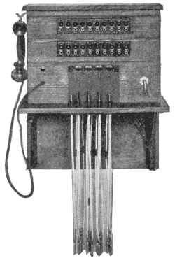
This line of switchboards is illustrated in Figs. 303 to 306. The beginning may be made with either a wall type or an upright type of switchboard, the former being mounted on brackets secured to the wall, and the latter on a table. A good idea of the wall type is shown in Fig. 303. Three different kinds of sectional units are involved in this: first, the unit which includes the cords, plugs, clearing-out drops, listening jacks, operator's telephone set and generator; second, the unit containing the line equipment, including a strip of ten magneto line signals and their corresponding jacks; third, the finishing top, which includes no equipment except the support for the operator's talking apparatus.
Fig. 304. Sectional Switchboard—Wall Type View full size illustration.
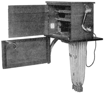
The first of the units in Fig. 303 forms the foundation on which the others are built. Two of the line-equipment units are shown; these provide for a total of twenty lines. The top rests on the upper line-equipment unit, and when it becomes necessary to add one or more line-equipment units as the switchboard grows, this top is merely taken off, the other line-equipment units put in place on top of those already existing, and the top replaced. The wall type of sectional switchboard is so arranged that the entire structure may be swung out from the wall, as indicated in Fig. 304, exposing all of the apparatus and wiring for inspection. Each of the sectional units is provided with a separate door, as indicated, so that the rear door equipment is added to automatically as the sections are added. In the embodiment of the sectional switchboard idea shown in these two figures just referred to, no ringing and listening keys are provided, but the operator's telephone and generator terminate in a special plug—the left-hand one shown in Fig. 303—and when the operator desires to converse with the connected subscribers, she does so by inserting the operator's plug into one of the jacks immediately below the clearing-out drop corresponding to the pair of plugs used in making the connection. The arrangement in this case is exactly the same in principle as that described in Fig. 292. The operator's generator is so arranged in connection with this left-hand operator's plug that the turning of the generator crank automatically switches the operator's telephone set off and switches the generator on, just the same as a switch hook may do in a subscriber's series telephone.
Fig. 305. Sectional Switchboard—Table Type View full size illustration.
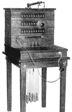
Fig. 306. Sectional Switchboard—Table Type View full size illustration.
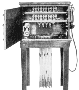
The upright type of sectional switchboard is shown in Figs. 305 and 306, which need no explanation in view of the foregoing, except to say that, in the particular instrument illustrated, ringing and listening keys are provided instead of the jack-and-plug arrangement of the wall type. In this case also, the top section carries an arm for supporting a swinging transmitter instead of the hook support for the combined transmitter and receiver.
ToC