Volume 1 — CHAPTER XI
Reading edition
NON-INDUCTIVE RESISTANCE DEVICES
It is often desired to introduce simple ohmic resistance into telephone circuits, in order to limit the current flow, or to create specific differences of potential at given points in the circuit.
Temperature Coefficient. The design or selection of resistance devices for various purposes frequently involves the consideration of the effect of temperature on the resistance of the conductor employed. The resistance of conductors is subject to change by changes in temperature. While nearly all metals show an increase, carbon shows a decrease in its resistance when heated.
The temperature coefficient of a conductor is a factor by which the resistance of the conductor at a given temperature must be multiplied in order to determine the change in resistance of that conductor brought about by a rise in temperature of one degree.
TABLE V
Temperature Coefficients
Pure Metals Temperature Coefficients
Centigrade Fahrenheit
Silver (annealed) 0.00400 0.00222
Copper (annealed) 0.00428 0.00242
Gold (99.9%) 0.00377 0.00210
Aluminum (99%) 0.00423 0.00235
Zinc 0.00406 0.00226
Platinum (annealed) 0.00247 0.00137
Iron 0.00625 0.00347
Nickel 0.0062 0.00345
Tin 0.00440 0.00245
Lead 0.00411 0.00228
Antimony 0.00389 0.00216
Mercury 0.00072 0.00044
Bismuth 0.00354 0.00197
Positive and Negative Coefficients. Those conductors, in which a rise in temperature produces an increase in resistance, are said to have positive temperature coefficients, while those in which a rise in temperature produces a lowering of resistance are said to have negative temperature coefficients.
The temperature coefficients of pure metals are always positive and for some of the more familiar metals, have values, according to Foster, as in Table V.
Iron, it will be noticed, has the highest temperature coefficient of all. Carbon, on the other hand, has a large negative coefficient, as proved by the fact that the filament of an ordinary incandescent lamp has nearly twice the resistance when cold as when heated to full candle-power.
Certain alloys have been produced which have very low temperature coefficients, and these are of value in producing resistance units which have practically the same resistance for all ordinary temperatures. Some of these alloys also have very high resistance as compared with copper and are of value in enabling one to obtain a high resistance in small space.
One of the most valuable resistance wires is of an alloy known as German silver. The so-called eighteen per cent alloy has approximately 18.3 times the resistance of copper and a temperature coefficient of .00016 per degree Fahrenheit. The thirty per cent alloy has approximately 28 times the resistance of copper and a temperature coefficient of .00024 per degree Fahrenheit.
For facilitating the design of resistance coils of German silver wire, Tables VI and VII are given, containing information as to length, resistance, and weight of the eighteen per cent and the thirty per cent alloys, respectively, for all sizes of wire smaller than No. 20 B. & S. gauge.
Special resistance alloys may be obtained having temperature coefficients as low as .000003 per degree Fahrenheit. Other alloys of nickel and steel are adapted for use where the wire must carry heavy currents and be raised to comparatively high temperatures thereby; for such use non-corrosive properties are specially to be desired. Such wire may be obtained having a resistance of about fifty times that of copper.
TABLE VI
18 Per Cent German Silver Wire
No. B. & S. Gauge Diameter Inches Weight Pounds per Foot Length Feet per Pound Resistance Ohms per Foot
21 .02846 .002389 418.6 .2333
22 .02535 .001894 527.9 .2941
23 .02257 .001502 665.8 .3710
24 .02010 .001191 839.5 .4678
25 .01790 .0009449 1058. .5899
26 .01594 .0007493 1335. .7438
27 .01419 .0005943 1683. .9386
28 .01264 .0004711 2123. 1.183
29 .01126 .0003735 2677. 1.491
30 .01003 .0002962 3376. 1.879
31 .008928 .0002350 4255. 2.371
32 .007950 .0001864 5366. 2.990
33 .007080 .0001478 6766. 3.771
34 .006304 .0001172 8532. 4.756
35 .005614 .00009295 10758. 5.997
36 .005000 .00007369 13569. 7.560
37 .004453 .00005845 17108. 9.532
38 .003965 .00004636 21569. 12.02
39 .003531 .00003675 27209. 15.16
40 .003145 .00002917 34282. 19.11
TABLE VII
30 Per Cent German Silver Wire
No. B. & S. Gauge Diameter Inches Weight Pounds per Foot Length Feet per Pound Resistance Ohms per Foot
21 .02846 .002405 415.8 .3581
22 .02535 .001907 524.4 .4513
23 .02257 .001512 661.3 .5693
24 .02010 .001199 833.9 .7178
25 .01790 .0009513 1051. .9051
26 .01594 .0007544 1326. 1.141
27 .01419 .0005983 1671. 1.440
28 .01264 .0004743 2108. 1.815
29 .01126 .0003761 2659. 2.287
30 .01003 .0002982 3353. 2.883
31 .008928 .0002366 4227. 3.638
32 .007950 .0001876 5330. 4.588
33 .007080 .0001488 6721. 5.786
34 .006304 .0001180 8475. 7.297
35 .005614 .00009358 10686. 9.201
36 .005000 .00007419 13478. 11.60
37 .004453 .00005885 16994. 14.63
38 .003965 .00004668 21424. 18.45
39 .003531 .00003700 27026. 23.26
40 .003145 .00002937 34053. 29.32
Inductive Neutrality. Where the resistance unit is required to be strictly non-inductive, and is to be in the form of a coil, special designs must be employed to give the desired inductive neutrality.
Provisions Against Heating. In cases where a considerable amount of heat is to be generated in the resistance, due to the necessity of carrying large currents, special precautions must be taken as to the heat-resisting properties of the structure, and also as to the provision of sufficient radiating surface or its equivalent to provide for the dissipation of the heat generated.
Fig. 117. Mica Card Resistance View full size illustration.
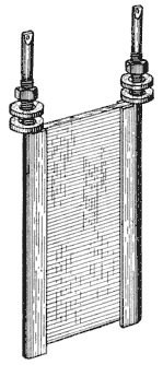
Types. Mica Card Unit. One of the most common resistance coils used in practice is shown in Fig. 117. This comprises a coil of fine, bare German silver wire wound on a card of mica, the windings being so spaced that the loops are not in contact with each other. The winding is protected by two cards of mica and the whole is bound in place by metal strips, to which the ends of the winding are attached. Binding posts are provided on the extended portions of the terminals to assist in mounting the resistance on a supporting frame, and the posts terminate in soldering terminals by which the resistance is connected into the circuit.
Differentially-Wound Unit. Another type of resistance coil is that in which the winding is placed upon an insulating core of heat-resisting material and wound so as to overcome inductive effects. In order to accomplish this, the wire to be bound on the core is doubled back on itself at its middle portion to form two strands, and these are wound simultaneously on the core, thus forming two spirals of equal number of turns. The current in traversing the entire coil must flow through one spiral in one direction with relation to the core, and in the opposite direction in the other spiral, thereby nullifying the inductive effects of one spiral by those of the other. This is called a non-inductive winding and is in reality an example of differential winding.
Lamp Filament. An excellent type of non-inductive resistance is the ordinary carbon-filament incandescent lamp. This is used largely in the circuits of batteries, generators, and other sources of supply to prevent overload in case of short circuits on the line. These are cheap, durable, have large current-carrying capacities, and are not likely to set things afire when overheated. An additional advantage incident to their use for this purpose is that an overload on a circuit in which they are placed is visibly indicated by the glowing of the lamp.
Obviously, the carbon-filament incandescent lamp, when used as a resistance, has, on account of the negative temperature coefficient of carbon, the property of presenting the highest resistance to the circuit when carrying no current, and of presenting a lower and lower resistance as the current and consequent heating increases. For some conditions of practice this is not to be desired, and the opposite characteristic of presenting low resistance to small currents and comparatively high resistance to large currents would best meet the conditions of practice.
Fig. 118. Iron-Wire Ballast View full size illustration.
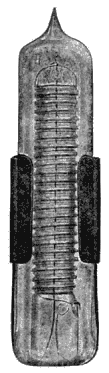
Iron-Wire Ballast. Claude D. Enochs took advantage of the very high positive temperature coefficient of iron to produce a resistance device having these characteristics. His arrangement possesses the compactness of the carbon-filament lamp and is shown in Fig. 118. The resistance element proper is an iron wire, wound on a central stem of glass, and this is included in an exhausted bulb so as to avoid oxidation. Such a resistance is comparatively low when cold, but when traversed by currents sufficient to heat it considerably will offer a very large increase of resistance to oppose the further increase of current. In a sense, it is a self-adjusting resistance, tending towards the equalization of the flow of current in the circuit in which it is placed.
ToC