Volume 1 — CHAPTER XVII
Reading edition
LOCK-OUT PARTY-LINE SYSTEMS
The party-line problem in rural districts is somewhat different from that within urban limits. In the latter cases, owing to the closer grouping of the subscribers, it is not now generally considered desirable, even from the standpoint of economy, to place more than four subscribers on a single line. For such a line selective ringing is simple, both from the standpoint of apparatus and operation; and moreover owing to the small number of stations on a line, and the small amount of traffic to and from such subscribers as usually take party-line service, the interference between parties on the same line is not a very serious matter.
For rural districts, particularly those tributary to small towns, these conditions do not exist. Owing to the remoteness of the stations from each other it is not feasible from the standpoint of line cost to limit the number of stations to four. A much greater number of stations is employed and the confusion resulting is distressing not only to the subscribers themselves but also to the management of the company. There exists then the need of a party-line system which will give the limited user in rural districts a service, at least approaching that which he would get if served by an individual line.
The principal investment necessary to provide facilities for telephone service is that required to produce the telephone line. In many cases the cost of instruments and apparatus is small in comparison with the cost of the line. By far the greater number of subscribers in rural districts are those who use their instruments a comparatively small number of times a day, and to maintain an expensive telephone line for the exclusive use of one such subscriber who will use it but a few minutes each day is on its face an economic waste. As a result, where individual line service is practiced exclusively one of two things must be true: either the average subscriber pays more for his service than he should, or else the operating company sells the service for less than it costs, or at best for an insufficient profit. Both of these conditions are unnatural and cannot be permanent.
The party-line method of giving service, by which a single line is made to serve a number of subscribers, offers a solution to this difficulty, but the ordinary non-selective or even selective party line has many undesirable features if the attempt is made to place on it such a large number of stations as is considered economically necessary in rural work. These undesirable features work to the detriment of both the user of the telephone and the operating company.
Many attempts have been made to overcome these disadvantages of the party line in sparsely settled communities, by producing what are commonly called lock-out systems. These, as their name implies, employ such an arrangement of parts that when the line is in use by any two parties, all other parties are locked out from the circuit and cannot gain access to it until the parties who are using it are through. System after system for accomplishing this purpose has been announced but for the most part these have involved such a degree of complexity and have introduced so many undesirable features as to seriously affect the smooth operation of the system and the reliability of the service.
We believe, however, in spite of numerous failures, that the lock-out selective-signaling party line has a real field of usefulness and that operating companies as well as manufacturing companies are beginning to appreciate this need, and as a result that the relief of the rural subscriber from the almost intolerable service he has often had to endure is at hand. A few of the most promising lock-out party-line systems now before the public will, therefore, be described in some detail.
Poole System. The Poole system is a lock-out system pure and simple, its devices being in the nature of a lock-out attachment for selective-signaling lines, either of the polarity or of the harmonic type wherein common-battery transmission is employed. It will be here described as employed in connection with an ordinary harmonic-ringing system.
In Fig. 188 there is shown a four-station party line equipped with Poole lock-out devices, it being assumed that the ringers at each station are harmonic and that the keys at the central office are the ordinary keys adapted to impress the proper frequency on the line for ringing any one of the stations. In addition to the ordinary talking and ringing apparatus at each subscriber's station, there is a relay of special form and also a push-button key.
Fig. 188. Poole Lock-Out System View full size illustration.
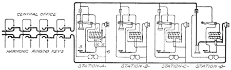
Each of the relays has two windings, one of high resistance and the other of low resistance. Remembering that the system to which this device is applied is always a common-battery system, and that, therefore, the normal condition of the line will be one in which there is a difference of potential between the two limbs, it will be evident that whenever any subscriber on a line that is not in use raises his receiver from its hook, a circuit will be established from the upper contact of the hook through the lever of the hook to the high-resistance winding 1 of the relay and thence to the other side of the line by way of wire 6. This will result in current passing through the high-resistance winding of the relay and the relay will pull up its armature. As soon as it does so it establishes two other circuits by the closure of the relay armature against the contacts 4 and 5.
The closing of the contact 4 establishes a circuit from the upper side of the line through the upper contact of the switch hook, thence through the contacts of the push button 3, thence through the low-resistance winding 2 of the relay to the terminal 4, thence through the relay armature and the transmitter to the lower side of the line. This low-resistance path across the line serves to hold the relay armature attracted and also to furnish current to the transmitter for talking. The establishment of this low-resistance path across the line does another important thing, however; it practically short-circuits the line with respect to all the high-resistance relay windings, and thus prevents any of the other high-resistance relay windings from receiving enough current to actuate them, should the subscriber at any other station remove his receiver from the hook in an attempt to listen in or to make a call while the line is in use. As a subscriber can only establish the proper conditions for talking and listening by the attraction of this relay armature at his station, it is obvious that unless he can cause the pulling up of his relay armature he can not place himself in communication with the line.
The second thing that is accomplished by the pulling up of the relay armature is the closure of the contacts 5, and that completes the talking circuit through the condenser and receiver across the line in an obvious fashion. The result of this arrangement is that it is the first party who raises his receiver from its hook who is enabled to successfully establish a connection with the line, all subsequent efforts, by other subscribers, failing to do so because of the fact that the line is short-circuited by the path through the low-resistance winding and the transmitter of the station that is already connected with the line.
A little target is moved by the action of the relay so that a visual indication is given to the subscriber in making a call to show whether or not he is successful in getting the use of the line. If the relay operates and he secures control of the line, the target indicates the fact by its movement, while if someone else is using the line and the relay does not operate, the target, by its failure to move, indicates that fact.
When one party desires to converse with another on the same line, he depresses the button 3 at his station until after the called party has been rung and has responded. This holds the circuit of his low-resistance winding open, and thus prevents the lock-out from becoming effective until the called party is connected with the line. The relay armature of the calling party does not fall back with the establishment of the low-resistance path at the called station, because, even though shunted, it still receives sufficient current to hold its armature in its attracted position. After the called party has responded, the button at the calling station is released and both low-resistance holding coils act in multiple.
No induction coil is used in this system and the impedance of the holding coil is such that incoming voice currents flow through the condenser and the receiver, which, by reference to the figure, will be seen to be in shunt with the holding coil. The holding coil is in series with the local transmitter, thus making a circuit similar to that of the Kellogg common-battery talking circuit already discussed.
A possible defect in the use of this system is one that has been common to a great many other lock-out systems, depending for their operation on the same general plan of action. This appears when the instruments are used on a comparatively long line. Since the locking-out of all the instruments that are not in use by the one that is in use depends on the low-resistance shunt that is placed across the line by the instrument that is in use, it is obvious that, in the case of a long line, the resistance of the line wire will enter into the problem in such a way as to tend to defeat the locking-out function in some cases. Thus, where the first instrument to use the line is at the remote end of the line, the shunting effect that this instrument can exert with respect to another instrument near the central office is that due to the resistance of the line plus the resistance of the holding coil at the end instrument. The resistance of the line wire may be so high as to still allow a sufficient current to flow through the high-resistance coil at the nearer station to allow its operation, even though the more remote instrument is already in use.
Coming now to a consideration of the complete selective-signaling lock-out systems, wherein the selection of the party and the locking out of the others are both inherent features, a single example of the step-by-step, and of the broken-line selective lock-out systems will be discussed.
Step-by-Step System. The so-called K.B. system, manufactured by the Dayton Telephone Lock-out Manufacturing Company of Dayton, Ohio, operates on the step-by-step principle. The essential feature of the subscriber's telephone equipment in this system is the step-by-step actuating mechanism which performs also the functions of a relay. This device consists of an electromagnet having two cores, with a permanent polarizing magnet therebetween, the arrangement in this respect being the same as in an ordinary polarized bell. The armature of this magnet works a rocker arm, which, besides stepping the selector segment around, also, under certain conditions, closes the bell circuit and the talking circuit, as will be described.
Fig. 189. K.B. Lock-Out System View full size illustration.
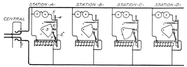
Referring first to Fig. 189, which shows in simplified form a four-station K.B. lock-out line, the electromagnet is shown at 1 and the rocker arm at 2. The ratchet 3 in this case is not a complete wheel but rather a segment thereof, and it is provided with a series of notches of different depths. It is obvious that the depth of the notches will determine the degree of movement which the upper end of the rocker arm may have toward the left, this being dependent on the extent to which the pawl 6 is permitted to enter into the segment. The first or normal notch, i.e., the top notch, is always of such a depth that it will allow the rocker-arm lever 2 to engage the contact lever 4, but will not permit the rocker arm to swing far enough to the left to cause that contact to engage the bell contact 5. As will be shown later, the condition for the talking circuit to be closed is that the rocker arm 2 shall rest against the contact 4; and from this we see that the normal notch of each of the segments 3 is of such a depth as to allow the talking circuit at each station to be closed. The next notch, i.e., the second one in each disk, is always shallow, as are all of the other notches except one. A deep notch is placed on each disk anywhere from the third to the next to the last on the segment. This deep notch is called the selective notch, and it is the one that allows of contact being made with the ringer circuit of that station when the pawl 6 drops into it. The position of this notch differs on all of the segments on a line, and obviously, therefore, the ringer circuit at any station may be closed to the exclusion of all the others by stepping all of the segments in unison until the deep notch on the segment of the desired station lies opposite to the pawl 6, which will permit the rocker arm 2 to swing so far to the left as to close not only the circuit between 2 and 4, but also between 2, 4, and 5. In this position the talking and the ringing circuits are both closed.
The position of the deepest notch, i.e., the selective notch, on the circumference of the segment at any station depends upon the number of that station; thus, the segment of Station 4 will have a deep notch in the sixth position; the segment for Station 9 will have a deep notch in the eleventh position; the segment for any station will have a deep notch in the position corresponding to the number of that station plus two.
From what has been said, therefore, it is evident that the first, or normal, notch on each segment is of such a depth as to allow the moving pawl 6 to fall to such a depth in the segment as to permit the rocker arm 2 to close the talking circuit only. All of the other notches, except one, are comparatively shallow, and while they permit the moving pawl 6 under the influence of the rocker arm 2 to move the segment 3, yet they do not permit the rocker arm 2 to move so far to the left as to close even the talking circuit. The exception is the deep notch, or selective notch, which is of such depth as to permit the pawl 6 to fall so far into the segment as to allow the rocker arm 2 to close both the talking and the ringing circuits. Besides the moving pawl 6 there is a detent pawl 7. This always holds the segment 3 in the position to which it has been last moved by the moving pawl 6.
The actuating magnet 1, as has been stated, is polarized and when energized by currents in one direction, the rocker arm moves the pawl 6 so as to step the segment one notch. When this relay is energized by current in the opposite direction, the operation is such that both the moving pawl 6 and the detent pawl 7 will be pulled away from the segment, thus allowing the segment to return to its normal position by gravity. This is accomplished by the following mechanism: An armature stop is pivoted upon the face of the rocker arm so as to swing in a plane parallel to the pole faces of the relay, and is adapted, when the relay is actuated by selective impulses of one polarity, to be pulled towards one of the pole faces where it acts, through impact with a plate attached to the pole face of the relay, as a limiting means for the motion of the rocker arm when the rocker arm is actuated by the magnet. When, however, the relay is energized by current in the opposite direction, as on a releasing impulse, the armature stop swings upon its pivot towards the opposite pole face, in which position the lug on the end of the armature stop registers with a hole in the plate on the relay, thus allowing the full motion of the rocker arm when it is attracted by the magnet. This motion of the rocker arm withdraws the detent pawl from engagement with the segment as well as the moving pawl, and thereby permits the segment to return to its normal position. As will be seen from Fig. 189, each of the relay magnets 1 is permanently bridged across the two limbs of the line.
Each station is provided with a push button, not shown, by means of which the subscriber who makes a call may prevent the rocker arm of his instrument from being actuated while selective impulses are being sent over the line. The purpose of this is to enable one party to make a call for another on the same line, depressing his push button while the operator is selecting and ringing the called party. The segment at his own station, therefore, remains in its normal position, in which position, as we have already seen, his talking circuit is closed; all of the other segments are, however, stepped up until the ringing and talking circuits of the desired station are in proper position, at which time ringing current is sent over the line. The segments in Fig. 189, except at Station C, are shown as having been stepped up to the sixth position, which corresponds to the ringing position of the fourth station, or Station D. The condition shown in this figure corresponds to that in which the subscriber at Station C originated the call and pressed his button, thus retaining his own segment in its normal position so that the talking circuits would be established with Station D.
When the line is in normal position any subscriber may call central by his magneto generator, not shown in Fig. 189, which will operate the drop at central, but will not operate any of the subscribers' bells, because all bell circuits are normally open. When a subscriber desires connection with another line, the operator sends an impulse back on the line which steps up and locks out all instruments except that of the calling subscriber.
Fig. 190. K.B. Lock-Out Station View full size illustration.
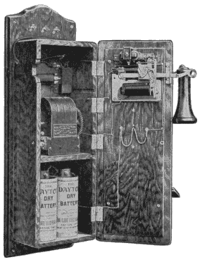
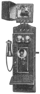
A complete K.B. lock-out telephone is shown in Fig. 190. This is the type of instrument that is usually furnished when new equipment is ordered. If, however, it is desired to use the K.B. system in connection with telephones of the ordinary bridging type that are already in service, the lock-out and selective mechanism, which is shown on the upper inner face of the door in Fig. 190, is furnished separately in a box that may be mounted close to the regular telephone and connected thereto by suitable wires, as shown in Fig. 191. It is seen that this instrument employs a local battery for talking and also a magneto generator for calling the central office.
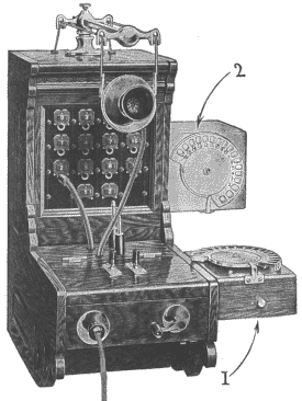
The central-office equipment consists of a dial connected with an impulse wheel, together with suitable keys by which the various circuits may be manipulated. This dial and its associated mechanism may be mounted in the regular switchboard cabinet, or it may be furnished in a separate box and mounted alongside of the cabinet in either of the positions shown at 1 or 2 of Fig. 192.
In order to send the proper number of impulses to the line to call a given party, the operator places her finger in the hole in the dial that bears the number corresponding to the station wanted and rotates the dial until the finger is brought into engagement with the fixed stop shown at the bottom of the dial in Fig. 192. The dial is then allowed to return by the action of a spring to its normal position, and in doing so it operates a switch within the box to make and break the battery circuit the proper number of times.
Operation. A complete description of the operation may now be had in connection with Fig. 193, which is similar to Fig. 189, but contains the details of the calling arrangement at the central office and also of the talking circuits at the various subscribers' stations.
Fig. 191. K.B. Lock-Out Station View full size illustration.
Referring to the central-office apparatus the usual ringing key is shown, the inside contacts of which lead to the listening key and to the operator's telephone set as in ordinary switchboard practice. Between the outside contact of this ringing key and the ringing generator there is interposed a pair of contact springs 8-8 and another pair 9-9. The contact springs 8 are adapted to be moved backward and forward by the impulse wheel which is directly controlled by the dial under the manipulation of the operator. When these springs 8 are in their normal position, the ringing circuit is continued through the release-key springs 9 to the ringing generator. These springs 8 occupy their normal position only when the dial is in its normal position, this being due to the notch 10 in the contact wheel. At all other times, i.e., while the impulse wheel is out of its normal position, the springs 8-8 are either depressed so as to engage the lower battery contacts, or else held in an intermediate position so as to engage neither the battery contacts nor the generator contacts.
Fig. 192. Calling Apparatus K.B. System View full size illustration.
When it is desired to call a given station, the operator pulls the subscriber's number on the dial and holds the ringing key closed, allowing the dial to return to normal. This connects the impulse battery to the subscriber's line as many times as is required to move the subscriber's sectors to the proper position, and in such direction as to cause the stepping movement of the various relays. As the impulse wheel comes to its normal position, the springs 8, associated with it, again engage their upper contacts, by virtue of the notch 10 in the impulse wheel, and this establishes the connection between the ringing generator and the subscriber's line, the ringing key being still held closed. The pulling of the transmitter dial and holding the ringing key closed, therefore, not only sends the stepping impulses to line, but also follows it by the ringing current. The sending of five impulses to line moves all of the sectors to the sixth notch, and this corresponds to the position necessary to make the fourth station operative. Such a condition is shown in Fig. 193, it being assumed that the subscriber at Station C originated the call and pressed his own button so as to prevent his sector from being moved out of its normal position. As a result of this, the talking circuit at Station C is left closed, and the talking and the ringing circuit of Station D, the called station, are closed, while both the talking and the ringing circuits of all the other stations are left open. Station D may, therefore, be rung and may communicate with Station C, while all of the other stations on the line are locked out, because of the fact that both their talking and ringing circuits are left open.
Fig. 193. Circuit K.B. System View full size illustration.
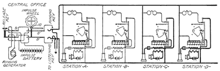
When conversation is ended, the operator is notified by the usual clearing-out signal, and she then depresses the release button, which brings the springs 9 out of engagement with the generator contact but into engagement with the battery contact in such relation as to send a battery current on the line in the reverse direction from that sent out by the impulse wheel. This sends current through all of the relays in such direction as to withdraw both the moving and the holding pawls from the segments and thus allow all of the segments to return to their normal positions. Of course, in thus establishing the release current, it is necessary for the operator to depress the ringing key as well as the release key.
A one-half microfarad condenser is placed in the receiver circuit at each station so that the line will not be tied up should some subscriber inadvertently leave his receiver off its hook. This permits the passage of voice currents, but not of the direct currents used in stepping the relays or in releasing them.
The circuit of Fig. 193 is somewhat simplified from that in actual practice, and it should be remembered that the hook switch, which is not shown in this figure, controls in the usual way the continuity of the receiver and the transmitter circuits as well as of the generator circuits, the generator being attached to the line as in an ordinary telephone.
Broken-Line System. The broken-line method of accomplishing selective signaling and locking-out on telephone party lines is due to Homer Roberts and his associates.
Fig. 194. Roberts Latching Relay View full size illustration.
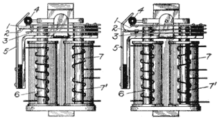
To understand just how the principles illustrated in Figs. 186 and 187 are put into effect, it will be necessary to understand the latching relay shown diagrammatically in its two possible positions in Fig. 194, and in perspective in Fig. 195. Referring to Fig. 194, the left-hand cut of which shows the line relay in its normal position, it is seen that the framework of the device resembles that of an ordinary polarized ringer. Under the influence of current in one direction flowing through the left-hand coil, the armature of this device depresses the hard rubber stud 4, and the springs 1, 2, and 3 are forced downwardly until the spring 2 has passed under the latch carried on the spring 5. When the operating current through the coil 6 ceases, the pressure of the armature on the spring 1 is relieved, allowing this spring to resume its normal position and spring 3 to engage with spring 2. The spring 2 cannot rise, since it is held by the latch 5, and the condition shown in the right-hand cut of Fig. 194 exists. It will be seen that the spring 2 has in this operation carried out just the same function as the switch lever performed as described in connection with Figs. 186 and 187. An analysis of this action will show that the normal contact between the springs 1 and 2, which contact controls the circuit through the relay coil and the bell, is not broken until the coil 6 is de-energized, which means that the magnet is effective until it has accomplished its work. It is impossible, therefore, for this relay to cut itself out of circuit before it has caused the spring 2 to engage under the latch 5. If current of the proper direction were sent through the coil 7 of the relay, the opposite end of the armature would be pulled down and the hard rubber stud at the left-hand end of the armature would bear against the bent portion of the spring 5 in such manner as to cause the latch of this spring to release the spring 2 and thus allow the relay to assume its normal, or unlatched, position.
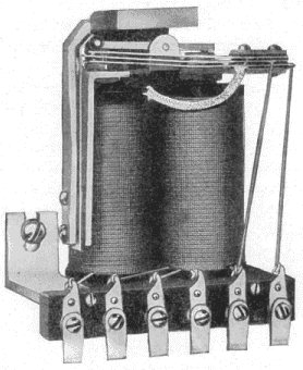
A good idea of the mechanical construction of this relay may be obtained from Fig. 195. The entire selecting function of the Roberts system is performed by this simple piece of apparatus at each station.
Fig. 195. Roberts Latching Relay View full size illustration.
The diagram of Fig. 196 shows, in simplified form, a four-station line, the circuits being given more in detail than in the diagrams of Chapter XVI.
It will be noticed that the ringer and the relay coil 6 at the first station are bridged across the sides of the line leading to the central office. In like manner the bell and the relay magnets are bridged across the two limbs of the line leading into each succeeding station, but this bridge at each of the stations beyond Station A is ineffective because the line extension Rx is open at the next station nearest the central office.
Fig. 196. Simplified Circuits of Roberts System View full size illustration.
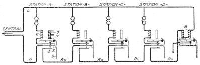
In order to ring Station A it is only necessary to send out ringing current from the central office. This current is in such direction as not to cause the operation of the relay, although it passes through the coil 6. If, on the other hand, it is desired to ring Station B, a preliminary impulse would be sent over the metallic circuit from the central office, which impulse would be of such direction as to operate the relay at Station A, but not to operate the bell at that station. The operation of the relay at Station A causes the spring 2 of this relay to engage the spring 3, thus extending the line on to the second station. After the spring 2 at Station A has been forced into contact with the spring 3, it is caught by the latch of the spring 5 and held mechanically. When the impulse from the central office ceases, the spring 1 resumes its normal position, thus breaking the bridge circuit through the bell at that station. It is apparent now that the action of coil 6 at Station A has made the relay powerless to perform any further action, and at the same time the line has been extended on to the second station. A second similar impulse from the central office will cause the relay at Station B to extend the line on to Station C, and at the same time break the circuit through the operating coil and the bell at Station B. In this way any station may be picked out by sending the proper number of impulses to operate the line relays of all the stations between the station desired and the central office, and having picked out a station it is only necessary to send out ringing current, which current is in such direction as to ring the bell but not to operate the relay magnet at that station.
In Fig. 197, a four-station line, such as is shown in Fig. 196, is illustrated, but the condition shown in this is that existing when two preliminary impulses have been sent over the line, which caused the line relays at Station A and Station B to be operated. The bell at Station C is, therefore, the only one susceptible to ringing current from the central office.
Fig. 197. Simplified Circuits of Roberts System View full size illustration.
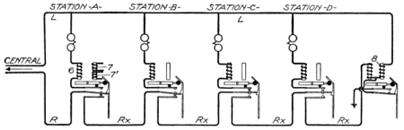
Since only one bell and one relay are in circuit at any one time, it is obvious that all of the current that passes over the line is effective in operating a single bell or relay only. There is no splitting up of the current among a large number of bells as in the bridging system of operating step-by-step devices, which method sometimes so greatly reduces the effective current for each bell that it is with great difficulty made to respond. All the energy available is applied directly to the piece of apparatus at the time it is being operated. This has a tendency toward greater surety of action, and the adjustment of the various pieces of apparatus may be made with less delicacy than is required where many pieces of apparatus, each having considerable work to do, must necessarily be operated in multiple.
The method of unlatching the relays has been briefly referred to. After a connection has been established with a station in the manner already described, the operator may clear the line when it is proper to do so by sending impulses of such a nature as to cause the line relays of the stations beyond the one chosen to operate, thus continuing the circuit to the end of the line. The operation of the line relay at the last station brings into circuit the coil 8, Figs. 196 and 197, of a grounding device. This is similar to the line relay, but it holds its operating spring in a normally latched position so as to maintain the two limbs of the line disconnected from the ground. The next impulse following over the metallic circuit passes through the coil 8 and causes the operation of this grounding device which, by becoming unlatched, grounds the limb L of the line through the coil 8. This temporary ground at the end of the line makes it possible to send an unlocking or restoring current from the central office over the limb L, which current passes through all of the unlocking coils 7, shown in Figs. 194, 196, and 197, thus causing the simultaneous unlocking of all of the line relays and the restoration of the line to its normal condition, as shown in Fig. 196.
Fig. 198. Details of Latching Relay Connections View full size illustration.
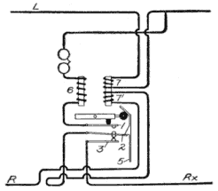
As has been stated, the windings 7 on the line relays are the unlatching windings. In Figs. 196 and 197, for the purpose of simplicity, these windings are not shown connected, but as a matter of fact each of them is included in series in the continuous limb L of the line. This would introduce a highly objectionable feature from the standpoint of talking over the line were it not for the balancing coils 7', each wound on the same core as the corresponding winding 7, and each included in series in the limb R of the line, and in such direction as to be differential thereto with respect to currents passing in series over the two limbs of the line.
The windings 7 are the true unlocking windings, while the windings 7' have no other function than to neutralize the inductive effects of these unlocking windings necessarily placed in series in the talking circuit. All of these windings are of low ohmic resistance, a construction which, as has previously been noted, brings about the desired effect without introducing any self-induction in the line, and without producing any appreciable effect upon the transmission. A study of Fig. 198 will make clear the connections of these unlocking and balancing windings at each station.
The statement of operation so far given discloses the general method of building up the line in sections in order to choose any party and of again breaking it up into sections when the conversation is finished. It has been stated that the same operation which selects the party wanted also serves to give that party the use of the line and to lock the others off. That this is true will be understood when it is stated that the ringer is of such construction that when operated to ring the subscriber wanted, it also operates to unlatch a set of springs similar to those shown in Fig. 194, this unlatching causing the proper connection of the subscriber's talking circuit across the limbs of the line, and also closing the local circuit through his transmitter. The very first motion of the bell armature performs this unlatching operation after which the bell behaves exactly as an ordinary polarized biased ringer.
Fig. 199. Broken-Back Ringer View full size illustration.
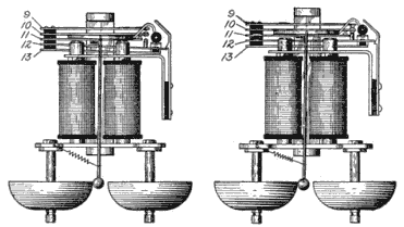
The construction of this ringer is interesting and is shown in its two possible positions in Fig. 199. The group of springs carried on its frame is entirely independent of the movement of the armature during the ringing operation. With reversed currents, however, the armature is moved in the opposite direction from that necessary to ring the bells, and this causes the latching of the springs into their normal position. In order that this device may perform the double function of ringer and relay the tapper rod of the bell is hinged on the armature so as to partake of the movements of the armature in one direction only. This has been called by the inventor and engineers of the Roberts system a broken-back ringer, a name suggestive of the movable relation between the armature and the tapper rod. The construction of the ringer is of the same nature as that of the standard polarized ringer universally employed, but a hinge action between the armature and the tapper rod, of such nature as to make the tapper partake positively of the movements of the armature in one direction, but to remain perfectly quiescent when the armature moves in the other direction, is provided.
Fig. 200. Details of Ringer Connection View full size illustration.
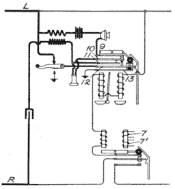
How this broken-back ringer controls the talking and the locking-out conditions may best be understood in connection with Fig. 200. The ringer springs are normally latched at all stations. Under these conditions the receiver is short-circuited by the engagement of springs 10 and 11, the receiver circuit is open between springs 10 and 12, and the local-battery circuit is open between springs 9 and 12. The subscribers whose ringers are latched are, therefore, locked out in more ways than one.
When the bell is rung, the first stroke it makes unlatches the springs, which assume the position shown in the right-hand cut of Fig. 199, and this, it will be seen from Fig. 200, establishes proper conditions for enabling the subscriber to transmit and to receive speech.
The hook switch breaks both transmitter and receiver circuits when down and in raising it establishes a momentary circuit between the ground and the limb L of the line, both upper and lower hook contacts engaging the hook lever simultaneously during the rising of the hook.
The mechanism at the central office by which selection of the proper station is made in a rapid manner is shown in Fig. 201. It has already been stated that the selection of the proper subscriber is brought about by the sending of a predetermined number of impulses from the central office, these impulses passing in one direction only and over the metallic circuit. After the proper party has been reached, the ringing current is put on in the reverse direction.
Fig. 201. Central-Office Impulse Transmitter View full size illustration.
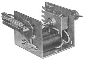
The operator establishes the number of impulses to be sent by placing the pointer opposite the number on the dial corresponding to the station wanted. The ratchet wheel is stepped around automatically by each impulse of current from an ordinary pole changer such as is employed in ringing biased bells. When the required number of impulses has been sent, a projection, carried on a group of springs, drops into a notch on the drum of the selector shaft, which operation instantly stops the selecting current impulses and at the same time throws on the ringing current which consists of impulses in the reverse direction. So rapidly does this device operate that it will readily follow the impulses of an ordinary pole changer, even when this is adjusted to its maximum rate of vibration.
Operation. Space will not permit a full discussion of the details of the central-office selective apparatus, but a general resumé of the operation of the system may now be given, with the aid of Fig. 202, which shows a four-station line with the circuits of three of the stations somewhat simplified. In this figure Station A, Station B, and Station D are shown in their locked-out positions, A and B having been passed by the selection and ringing of Station C, while Station D is inoperative because it was not reached in the selection and the line is still broken at Station C. Station C, therefore, has possession of the line.
When the subscriber at Station C raised his receiver in order to call central, a "flash" contact was made as the hook moved up, which momentarily grounded the limb L of the line. (See Fig. 200.) This "flash" contact is produced by the arrangement of the hook which assures that the lower contact shall, by virtue of its flexibility, follow up the hook lever until the hook lever engages the upper contact, after which the lower contact breaks. This results in the momentary connection of both the upper and the lower contacts of the hook with the lever, and, therefore, the momentary grounding of the limb L of the line. This limb always being continuous serves, when this "flash" contact is made, to actuate the line signal at the central office.
Fig. 202. Circuits of Roberts Line View full size illustration.
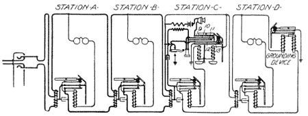
Since, however, all parties on the line are normally locked out of talking circuits, some means must be provided whereby the operator may place the signaling party in talking connection and leave all the other instruments on the line in their normally locked-out position. In fact, the operator must be able automatically to pick out the station that signaled in, and operate the ringer to unlatch the springs controlling the talking circuit of that station. Accordingly the operator sends impulses on the line, from a grounded battery, which are in the direction to operate the line relays and to continue the line circuit to the station calling. When, after a sufficient number of impulses, this current reaches that station it finds a path to ground from the limb L. This path is made possible by the fact that the subscriber's receiver is off its hook at that station. In order to understand just how this ground connection is made, it must be remembered that each of the ringer magnets is energized with each selecting impulse, but in such a direction as not to ring the bells, it being understood that all of the ringer mechanisms are normally latched. When the selecting impulse for Station C arrives, it passes through the ringer and the selecting relay coils at that station and starts to operate the remainder of the ringers sufficiently to cause the spring 12 to engage the spring 13. This establishes the ground connection from the limb L of the line, the circuit being traced through limb L through the upper contact of the switch, thence through springs 12 and 13 to ground, and this, before the line relay has time to latch, operates the quick-acting relay at the central office, which acts to cut off further impulses, and thus automatically stops at the calling station. Ringing current in the opposite direction is then sent to line; this unlatches the ringer springs and places the calling subscriber in talking circuit. When the operator has communicated with the calling subscriber, and found, for example, that another party on another similar line is desired, she turns the dial pointer on the selector to the number corresponding to the called-for party's number on that line, and presses the signal key. Pressing this key causes impulses to "run down the line," selecting the proper party and ringing his bell in the manner already described. The connection between the two parties is then established, and no one else can in any possible way, except by permission of the operator, obtain access to the line.
It is obvious that some means must be provided for restoring the selecting relays to normal after a conversation is finished. By referring to Fig. 194 it will be seen that the upper end of the latch spring 5 is bent over in such a manner that when the armature is attracted by current flowing through the coil 7, the knob on the left-hand end of the armature on rising engages with the bent cam surface and forces back the latch, permitting spring 2 to return to its normal position.
To restore the line the operator sends out sufficient additional selective impulses to extend the circuit to the end of the line, and thus brings the grounder into circuit. The winding of the grounder is connected in such a manner that the next passing impulse throws off its latch, permitting the long spring to contact with the ground spring. The operator now sends a grounded impulse over the continuous limb L of the line which passes through the restoring coils 7 at all the stations and through the right-hand coil of the grounding device to ground. The selecting relays are, therefore, simultaneously restored to normal. The grounder is also energized and restored to its normal position by the same current.
If a party in calling finds that his own line is busy and he cannot get central, he may leave his receiver off its hook. When the party who is using the line hangs up his receiver the fact that another party desires a connection is automatically indicated to the operator, who then locks out the instrument of the party who has just finished conversation and passes his station by. When the operator again throws the key, the waiting subscriber is automatically selected in the same manner as was the first party. If there are no subscribers waiting for service, the stop relay at central will not operate until the grounder end of the line is unlatched, the selecting relays being then restored automatically to normal.
The circuits are so organized that at all times whether the line is busy or not, the movement up and down of the switch hook, at any sub-station, operates a signal before the operator. Such a movement, when made slowly and repeatedly, indicates to the operator that the subscriber has an emergency call and she may use her judgment as to taking the line away from the parties who are using it, and finding out what the emergency call is for. If the operator finds that the subscriber has misused this privilege of making the emergency call, she may restore the connection to the parties previously engaged in conversation.
One of the salient points of this Roberts system is that the operator always has control of the line. A subscriber is not able even to use his own battery till permitted to do so. A subscriber who leaves his receiver off its hook in order that he may be signaled by the operator when the line is free, causes no deterioration of the local battery because the battery circuit is held open by the switch contacts carried on the ringer. It cannot be denied, however, that this system is complicated, and that it has other faults. For instance, as described herein, both sides of the line must be looped into each subscriber's station, thus requiring four drop, or service, wires instead of two. It is possible to overcome this objection by placing the line relays on the pole in a suitably protected casing, in which case it is sufficient to run but two drop wires from the nearer line to station. There are undoubtedly other objections to this system, and yet with all its faults it is of great interest, and although radical in many respects, it teaches lessons of undoubted value.
ToC