PART FOURTH. (continued 2)
Reading edition
OF A NEW SPINNING MACHINE, Called, and being the Patent Eagle.
The Machine commonly used for continued Spinning, in low numbers, is named a Throstle: and as my Invention acts in a similar manner, I have presumed to call it an Eagle. My motive is no mystery. The Machine spins more and better than a throstle: and reaches, especially, to a fineness unknown in throstle spinning. It could not, therefore, justly receive a meaner name, nor even an equal one.
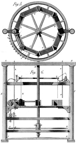
The present Machine then, is a superior kind of throstle, the construction of which will be understood, by spinners, from the annexed figures, 5 and 6 of Plate 40. As the principal difference between the former machines and this, resides in the toothed wheel by which it’s spindles are turned, we shall begin this description by adverting to it: A B is that wheel, cut, at present, into 800 inclined teeth, and working with pinions of 11 teeth, one of which, with it’s spindle, is shewn at a b, fig. 6. The revolutions, therefore, of these spindles to one of the wheel, are 72.7272, &c.; and since the latter, in spinning, makes from 60 to 70 turns per minute, the spindles run at the rate of 5000 turns in that time, and might do more if desired by the spinner. In a word, the useful speed depends on the size and weight of the spindles, the flyers, &c.
Immediately above and below the wheel A B, are two rings of cast iron, to which are screwed rims, either of wood or metal, destined to hold the steps and bolsters of the spindles, as is usual in a throstle, with the difference of the circular form, which the wheel of course requires; and the relation of which, to the rollers, is shewn at a b, fig. 5, being a plan of this Machine. Returning to fig. 6, the next object upward is the roller-beam, (cast hollow for lightness) the form of which is that of an octagon, with two brackets c d, by which it is fastened to the pillars E F: these, in their turn, being connected with the top and bottom cross-pieces (G H, I K) so as to make up the frame, properly so called. All these parts are placed (in section) similarly to those usually composing the throstle; and the copping motion is produced by the curve f, driven by an endless screw on the shaft h f, and acting on the slide f g, and through it on the ring of which the square i is a section: and on whose iron plate, in fine, the bobbins drag, as they do in the throstle. In the Machine before us, the rollers are driven by two side-shafts h f, which take their motion either from a train of spur wheels placed above the traverse G H, or by bevil wheels from two small shafts, coming under that traverse from the central shaft L M, to those h f, and acting on the rollers by means of the bevil wheels f m, seen in the figures. Now, the rollers are contained in eight heads—1, 2, 3, 4, 5, 6, 7, 8, each of which has it’s speed wheels in the angles n o, &c. and receive their motion from six sets of bevil wheels q, &c. which propagate the motion round each half of the Machine, from the points m and p respectively.
Above this roller-beam, is the creel-ring N O, which (either in one or two rows) receives the sixty roving bobbins that supply the sixty spindles, of which the Machine is composed: and whose threads pass under the eight sets of rollers—one thread being suppressed in each of the heads—1, 4, 5, 8, on account of the columns. (This, at least, is the arrangement I prefer; but some of the Machines have been made with eight threads in all the compartments.) Finally, in this frame G H, I K, is placed a ring P Q, (of glass or bright metal) over which the rovings are thrown before they are put in the guides behind the rollers; so that the route of a thread in the act of being spun, is shewn in fig. 5, by the line P R, S b, where it meets the bobbin on the spindle a b, before mentioned.
It may be observed here, to prevent ambiguity, that the guide-boards, with their hooks, are placed below the octagon roller-beam q n o, &c. as they are in the common throstle; being, each, 1⁄8 of the whole circumference, and of a circular form on the outside, reaching, by these hooks, to the point S, so as to hold the thread just over the centre of the spindles as at a b, fig. 6. Considering this as a commonplace subject, I have not attempted to draw these boards, since their form and position would occur to every constructor: and this is the reason also, why I have given only the section of the copping ring i, fig. 6: nor at all shewn the top rollers—nor the detail of the creel—on all which topics, opinions vary considerably, while the things themselves are really of minor importance.
There is, however, in my Patent System, something which I think important, and which, therefore, I have sketched near Q, fig. 6. If w x be there considered as the second communication shaft, a wheel z is put on it, of that kind which is calculated to work in a certain geering chain, called in French chaine de Vaucanson, (from the name of it’s inventor); and further, similar wheels (y) are connected with all the pins on the creel, round which the chain is carried from the wheel z, till it comes to it again. The consequence is, that all the wheels (y) are turned by that chain, so as to untwist the roving while the spinning rollers draw it off the bobbins: and this is so, because, in my Patent System, the rovings are over-twisted, in order to admit their being made very fast, without the danger of breaking. This then, completes my Patent Eagle, formed, on the right hand of the figure so as to use over-twisted roving; and on the left hand, so as to spin common roving in the usual manner. In both cases, the motion of the spindles by geering, ensures a mathematical twist, and thus produces yarn better than common; whence also it’s fineness can be carried much farther than on a common throstle. It need hardly be added, that these spindles are stopped and set in motion by the mechanism described in my second Part, at fig. 1, Plate 19: and there mentioned as “a Machine to set-on and suspend rapid motions.”
OF A SECOND SPINNING MACHINE, Adapted principally to Wool.
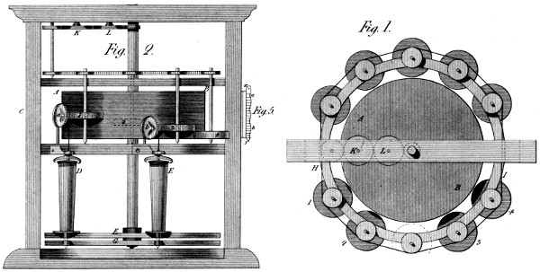
This Machine, represented in Plate 41, figures 1 and 2, may be called a Spinning-card: whose use, however, I shall now suppose confined to spinning coarse yarn, or rather rovings, to be re-spun on the common machines, or on machines similar to my Eagle just described. It consists, in reality, of an horizontal card A B, having it’s flyer, &c. adapted to perform, in a perpendicular position, what those several parts do, in an horizontal one, on the common carding engine. All this is so well known, that I have not thought it necessary to draw it in these figures; but merely to say, that in this Machine, those operations are performed on the left hand, as at A, where is introduced a broad flat ribbon of wool, duly made on a preparing card, and laid on edge in a box at C, from whence it is drawn by the feeding rollers, &c. so as to cover the whole of the central card A B. Now, round this central card, are placed, ten or more small fillet cards, 1, 2, 3, 4, &c. being at different heights on the central one; by which arrangement, the whole surface of the latter is stripped by these cards, and as much filament collected on each, as is sufficient to form a thread or roving, as before mentioned. But, further, these small cards have to be stripped in their turn: and that is done by the circular combs a b, which being placed obliquely to the cards, receive motion from them, and gather a regular mass of filament of a size fitted to become the yarn or roving in question. Nor need this roving be re-drawn, by rollers, before it is twisted: for it is the property of the bobbins D E, fig. 2, to draw mathematically: and with any speed that shall have been determined. If we examine how this is done, we shall see at bottom, two wheels F G, (toothed on the patent principle) one of which drives the spindles and flies, and the other the bobbins D E: the wheel that drives the bobbin having a few teeth more than that which drives the spindles—whose pinion is the same in number as that of the bobbin. Thus, therefore, the bobbin goes as much faster than the spindle as is necessary to take up all the wool furnished by the comb, and to the comb by the small card, which receives it from the central card A B; where note—that the draught, by this difference of motion is not variable, but determined: since the heads of the bobbins E D, are a hollow inverted truncated cone, on which the yarn cannot remain—for in winding, it drives downward that which is already wound, so as to fill the whole bobbin from the head—a reason for the conical shape of the latter object.
It will appear by the upper figure, (which is a plan of the central card, and the small cards, 1 2, &c.) that the latter receive their motion from the chain H I, by means of the train of wheels K L, turning on studs in the upper cross-piece. Suffice it to add, that the centres of these cards, of the combs, &c. are fixed to the rings by proper cramps, as will be easily conceived. I have offered to sight, only the essential parts, to avoid confusion: and I presume to hope every thing important will be thus seen without difficulty.
In my present view of this Invention as a preparing Machine, I would observe, that the central card is only considered as a distributor, and that I should, now, add to it a System of machinery to make it a forced distributor. I had, indeed, prepared this very System to be patentized many years ago: but the delays that occurred then, followed by the Restoration, (which gave me an opportunity of coming to England;) made me suspend this intention—respecting a method, perhaps, the only thing wanted to make this Machine in all respects excellent.
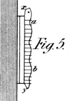
In the small figure 5, (Plate 41) x y is supposed to be the section of a central card, such as A B, fig. 2; and the horizontal lines between x and y, shew the height of the card teeth. Of these, I take out a portion in several perpendicular lines round the card—say, at an inch distance from each other: the intervals thus stripped, being about 1⁄16 of an inch in width: and in all these upright slits, I introduce a blade x y, (whose transverse section is like that of a card wire) and whose edge is undulated as at a b. Finally, to these blades is given, (by a proper Machine) a slow up-and-down motion, which makes them push off the filament from the card wires at the highest points of the waves, and suffer the wires to retain these filaments at the lowest points; whence it follows, from the motion just mentioned, that these points of reception and exclusion of filament, are constantly changing on the surface of the whole card, and that, therefore, the card will never be totally clogged with wool—as it is in the common process. It will be seen that the use of this System need not interrupt that of the common flyer, (or stripping card) whose use is to keep the teeth in working order, and to discharge a part of the obtruding filament.
In terminating this article, I cannot resist the desire of recommending this whole subject to any opulent English Manufacturer, whose zeal and public spirit, are commensurate with the scope which these hints embrace, and to which they tend, if duly appreciated.
OF MY PARALLEL MOTION, As applied to HEAVY Steam Engines.
While this Invention, as described in page 30 of the first Part, is allowed to possess curious properties, and to be a pretty thing, opinions do not all concur in declaring it, essentially and generally, a good thing. Nor could I be unjust enough to insist that it is so, in every kind and magnitude of application. I have, however, convinced myself that it is susceptible of practical excellence, as a first motion to steam engines, whatever be their dimensions; and have, therefore, presumed to re-produce it, with those modifications which are required to make it so. In thus acting, I have again preferred the useful to the agreeable, and in some measure inverted the order of my subjects. But I trust this deviation will be excused, in favour of the motive and the result; on both which I feel a good degree of confidence.
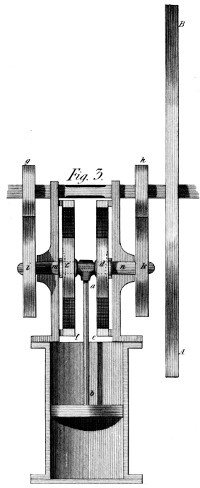
To obviate the point of mechanical weakness in this Parallel Motion, (see Plate 41, fig. 3,) I have doubled it’s parts; and brought the piston rod a b, to act, at once, on two of the circulating wheels c d, placed exactly opposite each other, and rolling, as before, on the inside of the fixed wheels f e, so as to produce the rectilinear motion, by the action of the piston rod on them both. And to make their respective motions one, (as connected with the fly B A) this latter is fixed to a shaft common to the two wheels g h, and by which, therefore, the two other wheels i k, fixed to the crank shafts m n, are kept in due position. Thus, then, is all winding or twisting motion done away: and, therefore, can this System be employed in engines of every required power. Nor need I add, (what will be generally allowed) that much of the expence, and of the retardation, which a given engine suffers from the beam, the connecting rod, &c. will thus be completely obviated.
I must, however, stop every gainsaying mouth, on the circumstance of using geering between the engine and the fly—a system which I acknowledge to have been hitherto an evil; though, perhaps, a necessary evil—as giving (by a simple method) a double speed to the fly from a single motion of the piston. At all events, in this shape, I submit only to a very common difficulty—and might there rest my apology.
But I should have hesitated to go thus far, had I not foreseen that all the evil arising from this use of wheels, can easily be avoided by my geering:—by means of which I am bold to say, every vestige of shake or backlash may be destroyed; and this method of working a steam engine be made as silent as when a beam is used: in which case, considerable advantages must accrue from this method.
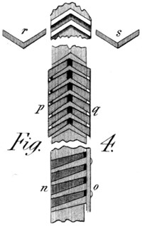
To come to the point:—the small figure 4, in Plate 41, relates to this subject. My geering is there seen in three forms or applications—each one intended to bring the above property into play. The part n o, represents the manner in which two wheels with singly-inclined teeth, work together when one of them is furnished with a cheek, as directed in fig. 3 of Plate 14. But here, in addition to that, the teeth of both wheels are sloped more on one side than on the other, so as to assume a wedge-like form: insomuch, that in beginning to work, (if not perfectly formed) the wheels would not occupy the same plane. For, in fact, the cheek screws press home the cheek o against a number of thin washers all round the wheel, and thus only draw the wedge-formed teeth into each other as they become bedded, and successive washers are taken away. Hence, a good degree of precision is obtained—accompanied with little friction, and thus with great durability.
But we stop not here. The part p q of this figure, shews a pair of wheels doubly inclined—one of them only, being made in two halves, which are connected together by screws and washers, like that just described. Here then, another degree of friction is got rid of—namely, that of the cheek o: but still, a small degree remains, (dependent on the double versed sine of the angle formed on the wheel’s circumference, by the thickness of a tooth). This quantity, is indeed, very minute; and brings, perhaps, the whole near enough to perfection. To do, however, completely away with all friction, (see my preceding statement)—as well in the wheel acting backward, as in that acting forward, we must do what is shewn in the parts r or s of fig. 4: we must have a pair of V wheels on the same shaft, with the power of turning one of them in reference to the other; and then connecting them by proper screws, &c. to preserve the position thus given: by which means, in a word, all shake or backlash will be completely annulled.