PART THIRD. (continued 2)
Reading edition
This Machine is further composed of a wheel C D, and a pinion E, to turn it with, either by hand, or by any proper application of power. The wheel turns the box A B, and thus agitates the contents in a way not dissimilar to the operation of the dash-wheels of calico printers. But, again, this wheel and vessel turn upon two hollow gudgeons c d; one of which is destined to convey cold water into the wheel from the reservoir F G, to regulate which is the use of the cock f: the stuffing box e being made as good as possible, in order to prevent all leakage, either of air or water. The second hollow axis d serves two purposes: it gives a passage to the fetid matter of which the expulsion is desired, and conveys it through the cock g to the sink or sough below h, without any communication with the surrounding atmosphere.
But we said this hollow gudgeon had a second use: it is to bring steam into the revolving vessel A B, from any proper boiler beyond K, when that part of the process requires it.—There are, moreover, two partitions C D, l m, made near the ends of the vessel, and pierced with many holes, in order to suffer the cold water to flow in, and the dirty water to escape, without choking up the respective passages: and, finally, at the eduction end of the Machine (see n, o, p, fig. 2), there are placed three pipes, reaching from the angles of the box to the hollow centre, and furnished, at those angles, with valves, opening outwards; which thus form a kind of hydraulic machine to raise this matter from those places to the hollow centre, and thus, after a certain number of revolutions, to expel it entirely.
The process, then, for cleansing the objects contained in the vessel A B (including the condition of cutting off all communication with the ambient space,) is as follows:—
1st.—These objects are dropped into the vessel as soon as produced, and the vessel is filled, one half or more, with cold water from the reservoir F G. The things are then left to steep in this bath for a day or two, or what space of time the periodical mutations of the house permit. By which operation alone, the miasmata are already much confined by the water, even though the lid of the vessel should be but partially shut: after which, this steeping operation may be continued, with the accompaniment of a few turns of the handle (E) to fully saturate every part of the mass. In the second place, a small stream of water is let through the cock f, and the wheel C D is kept turning for a few hours, to discharge the cold water and the most offensive matter, through the cock g, into the sink: and, thirdly, the steam-cock K is opened (that g being shut), by which means steam is brought into the vessel A B, and the whole soon raised to the boiling temperature. This state of things is continued, as long as it is found necessary; the motion, of course, being also continued, and even accelerated, that the mass of objects may fall from angle to angle, and be thus well washed—that is, well finished, if plain things; and fully prepared for finishing, by hand, if of a nature to require close attention. And, finally, in many cases, the warm process may now be abandoned, and a new stream of cold water be injected, accompanied by a due motion in the vessel, so as to rince the contents; and thus leave nothing to do for the laundresses, but to dry and mangle, or iron them; where, it is plain, that no inconvenience can have arisen from this process, either to these persons, or to the other inmates of the house.—Hence, then, this Machine has the properties announced—of confining the offensive matter until cleansed away.
OF A MACHINE, For propelling Boats, on narrow Canals, without disturbing the Water.
The application of steam-power, to the motion of boats on narrow canals, is, I believe, much impeded by the consideration that the agitation of the water injures their banks, and would finally destroy them. On the other hand, it is known, that to drive a vessel, by acting on a fleeting medium, such as water, we must, at once, submit to lose about one half of the whole power employed—that is, the power, armed with energy enough to produce the required velocity, must go through twice the space that constitutes the way or progress of the vessel. This depends, however, on the size of the floats or paddles employed, compared with the section of the boat, as modified by the form of the prow; but it is difficult to employ a paddle so large as to suffer more resistance from the water than the boat itself; and, if they are found just equal, the loss of power is exactly one half of the whole. These, then, are the two difficulties which I hoped to avoid, by the method now to be exhibited.
The idea is this—To have a large and heavy wheel A connected with a long shaft B, reaching from the boat to the shore, and, turning that wheel in the boat, to propel the latter, by means of it’s rolling motion, on the bank or track-way; or, in some cases, on a proper rack, placed there for that purpose.
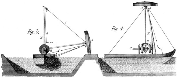
The Machine itself is represented in figs. 3 and 4, of Plate 31; fig. 3 being a stern-view, and fig. 4 a side-view, both of the machine and the vessel. C is an axis, placed along the vessel, and turned by any convenient power—as a horse, a steam-engine, &c. On this axis, considered as the first motion, are fixed the two bevil wheels b c, from which the long shaft B A of the rolling wheel takes it’s motion. The use of the two wheels b c, is to drive the boat in the same direction on whichever side of the boat the wheel A may be placed; for this, of course, must follow the track-way, which is sometimes to the right and sometimes to the left of the vessel.—Between the two wheels c b, is a sliding block (or catch-box) d, in which the shaft A B of the large wheel has it’s lower pivot, and by which it’s wheel B is almost instantaneously shifted from one to the other of the vertical wheels b c: the catch-box d being itself worked by a lever, of which the end only is seen at e, fig. 4. In fig. 3, there is further shewn a rope or stay f, which, fastened to the socket s, of the rolling wheel A, and fixed in the middle of the boat, at the greatest possible distance from it, serves to keep that shaft at or near an angle of 90 degrees with the boat’s side: so that (the vessel being long) it becomes easy by means of the rudder, assisted, perhaps, by lee-boards to keep the way of the boat in a line parallel to the shore, notwithstanding the tendency to veer outward, given by the wheel A, while acting on a point so far from the body of the vessel.
I further observe, that, in order to shift the apparatus, with a certain facility, from one side of the boat to the other, there is a mast M placed ahead of the mechanism just described, which rises as high as the length of the main-shaft (but can be lowered to pass a bridge, &c.), and to the top of which is fixed the block g, through which a rope passes from the foot of the mast to the above-mentioned socket of the wheel A. By this rope the wheel is hauled up till nearly ready to fall over the centre; when a push from below will complete that passage; and the wheel A, being afterwards lowered by the rope h i, will soon find it’s proper position on the other side of the boat, as before anticipated. Where, it should also be remembered, that this shaft must have a joint and socket, to permit it’s being bent, to pass a bridge, &c.
Hitherto we have supposed this rolling wheel to act on the bank or track-way solely by it’s weight; but this is not our only resource; for this wheel might be made of a moderate weight, and be pressed down by a brace reaching along the boat, toward the head and stern (see k l, fig. 3.), and hauled taught through an eye of the socket s; by which manœuvre (the points k l being lower than the centre A of the wheel) the latter will be pressed forcibly downward, and cause that cohesion there, from which the boat is ultimately to take her motion.
And, as to the wheel A itself, I have not represented it in the very form I should wish it to have, because it can be sufficiently described in words. I should cast this wheel (if made at all in metal) as a shell, the outside of which would be what is really seen in the figure (at A), and the rim would have in it mortices, like those which are made for iron wheels destined to receive wooden cogs, and geer with cogs of iron. In fact, this would become a wooden-toothed-wheel, with its teeth roughly formed and placed, so as to occasion a small expence, and to be easily changed, when worn away by the friction on the track-way. Thus would, I am persuaded, a very moderate weight in the wheel, and as moderate a pressure from the braces k l, connect the wheel with the road enough to produce the desired effect, with a trifling loss of the power employed. And thus might we navigate a narrow canal, with a great saving of expence; not to mention that other advantage of avoiding entirely that injury to the banks, which must attend every system of propelling the boats, founded on the agitation of it’s waters.
OF A MACHINE, For working, swiftly, the Slide-valves of Steam-engines.
The Slide-valve is an excellent substitute for the hand-geering of steam-engines, from the simplicity of form which it introduces, and the certainty of it’s recurring effects. But it is, I believe deservedly, reproached with being too sluggish in it’s operation, at the very moment when activity would be most desirable—namely, at the beginning of the strokes; insomuch, say some, that the power of the engine is materially lessened by it. The fact is, that the excentric (usually placed on the crank-shaft) is almost always moving, and with it the slide-valves also; which thus open by slow degrees, when they should open by rapid ones.
Without discussing the question further, I cannot refrain from introducing this application of the principle of my Parallel Motion, given in page 237; which appears to me greatly calculated to obviate these difficulties; and thus to leave the slide-valve in possession of all it’s own advantages, with the addition of those which have hitherto belonged exclusively to the Hand-geering System.
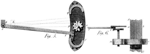
I have represented this Mechanism in figs. 5 and 6, Plate 31: where A B shew the crank-shaft of a steam-engine, working by means of slide-valves, the place of the excentric being at a b, in a line with the pulling-bar e f. Instead, then, of the usual connecting frame between the excentric at a b, and the valve-lever at g, I use for the above purpose, a lever e f terminated by an arc o, furnished (in the present instance) with five teeth, and connected by the joint e with the valve-lever g, in the usual manner. In the arc, which terminates this lever to the right, are the five teeth above-mentioned; and, they geer in the ten teeth of the wheel c d, which will be seen (in fig. 6) to be on the same shaft with the spur-wheel m, itself driven by the spur-wheel n, of twice the diameter. This wheel c d, therefore, makes two revolutions for one of the crank-shaft: and, supposing it to turn in the direction of the arrow, it will first of all draw upward the arc o, producing no effect on the valve-lever at g; but, when the tooth r is arrived at p (the tooth p being then arrived at the entrance of the curve q), the wheel c d will begin to draw the arc o along with it, round it’s own centre; and, the teeth of the arc being kept in it’s teeth by the similar curve q, the valve-bar will be drawn from g to h, in the course of one quarter of a revolution of the crank-shaft A B. But, now, the tooth r of the arc o will be found at s: and, therefore, the further revolution of the wheel c d will carry the arc o downward toward t, until the tooth r has reached the point t; that is, until the wheel c d has made another half-revolution, and the shaft A B another quarter; when, as before, the arc o, conducted by the curve t r, will again drive back the lever e f, till it comes into it’s present position: after which, their motions will be regularly continued. It is, then, evident, that the slide-valves are thus opened and shut, each during one quarter of a turn of the crank-shaft A B; and thus they remain stationary during another quarter, and that, in two positions of said shaft diametrically opposite to each other. And thus have we a simple mean, adaptable to every engine, of giving it much of the advantage of the hand-geering system, while preserving all that of the slide-valve principle. And, were it desired to lengthen the interregnum of the opening motion, it would be done by making the wheel c d smaller, and the ratio of n to m (see fig. 6) larger in the same proportion.
I observe here, however, that care should be taken not to make the valve motions too rapid, nor the intervals between them too long; for, I consider one of the best properties of this motion to be, that it acts like an excentric; that is, slowly at first, most rapidly afterwards, and finishes as slowly as it began; which is a precious quality in all reciprocating machines.
Finally, I would remark, that the two last rounds in the rack of the arc o might be rather larger than the intermediate ones, and turn, moreover, on pins, so as to suffer less friction when rolling on the conducting curves q and t. There might also be a plate or cap rivetted or screwed over all the teeth, so as to strengthen each one, by the force of the whole, as is shewn in fig. 1, Plate 29; from which, as before observed, this Mechanism is deduced.
The foregoing completes the Third Section of my work: and gives an article beyond the twenty, first intended:—which I thought important enough to claim this distinction. I now beg leave to add a remark or two on the text and plates of this, and the Second Part, by way of clearing up some obscurities, that might otherwise embarrass my readers.
And, first, in fig. 1, of Plate 21, the receiving vessel M, erroneously appears to form part of the wheel D E; but is, in reality, placed before it, as in all similar cases.—And, further, a small deviation of the circular lines, in Plate 22, has set the plate and it’s description, in page 192, at variance; the difference between the lines o p and C q being not “imperceptible,” as there stated. I wish, then, that the dotted radius A o p, in the said fig. 2, may be carried (or supposed) halfway between p and C. Finally, in page 200, line 8, the 24th Plate is incorrectly called the 25th.
I shall conclude this Part, by an observation or two on the reception my System of Toothed Wheels, as described in this work, has met with—not intending to speak of the local difficulties I experienced at a former period. But, here, the interests of truth force me to break silence. The necessity I stood under of bringing out this work in Parts, has, at least, had one advantage: it has given me an opportunity of watching the workings of prejudice—not to say of envy,—and thus of neutralizing, in some degree, the effects of either: from which, however, I claim nothing but the right of making my labours the more extensively useful, by making them better known. I have, then, to say that, among a few other objections to the System, this error has come from so respectable a quarter, that it would be unjust to Science, and injurious to truth, to let it pass unrefuted. It has been said, that “my wheels are a Chinese Invention;” and this proof has been adduced of it—namely, a sugar-mill, from China, having it’s cylinders fluted in a spiral direction. Now, the fact is, it would have been difficult to give a better proof that the wheels are NOT a “Chinese Invention;” for two inventions are then only alike when they produce the same effect, by similar means. But here the effects intended are totally different. A sugar-mill acts in or near the plane of the centres; and one of it’s cylinders is not intended to drive the other independently of pressure between them. This is so true, that the rollers of many sugar-mills are not fluted at all. Besides this, my wheels exert no pressure in that direction; and if they did, they would not be cog-wheels. In a word, their action is at right angles to the former, and has an object of quite a distinct nature. These, then, are by no means the same machine; and, therefore, mine is not a “Chinese Invention.”
Here, however, I beg not to be misunderstood! I should feel no regret at appearing on the mechanical stage, a few hundred years after so ancient and astonishing a nation as the Chinese! But, in this case, truth did not permit me to sanction, by my silence, this flagrant error.
Finally, an opinion exists, somewhere, that these wheels will never be generally used, from the difficulty of making them; and this opinion has been expressed, apparently, with no very amiable feeling. But, amiable or hateful, the opinion is highly erroneous! It is so far from fact, that, in a competent manufactory, they can be made more cheaply than others now are; and many persons are already calling for them from every quarter; nor is any thing wanted to insure their immediate prevalence but a common degree of commercial energy.