PART SECOND. (continued 2)
Reading edition
In using this mechanism, the vessel A B, would be filled, to a certain level, with oil or water, to prevent any blow from the returning arcs—which latter might be made to fall on a lining of leather, to avoid still further all commotion: and thus, even were these rollers not placed quite parallel to the shaft, this imperfection would be corrected by the frequent renewal of these movements, and the consequent absence of lateral friction between the arcs and the shaft. It may be observed that either of the above methods of destroying friction is not confined to the vertical direction: but may be so used as to receive the pressure caused, in any direction, by the action of a wheel or other agent. And with respect to the best use of each method respectively, I would propose the former for light and swift motions, and the latter for slow-going shafts, heavily laden: it being well understood that the shafts must be kept in their places, in the less essential directions, by proper steps, at the discretion of the person who employs these Machines.
Finally, I consider it as a matter of course, that all the surfaces coming into contact in these operations, should be as hard and impenetrable as possible. For if, by neglecting this precaution, any change of form occurred, what is said above could not be practically true: But these properties can be realized, with only those degrees of hardness that are often employed in the mechanical world. Thus a die of hardened steel, bears almost unimpaired, the strokes and pressure it suffers in the coining-press. A chisel, stands thousands of blows and cuts hard metal, without sensibly giving way. The knife-edges which carry a heavy pendulum, suffer it to vibrate many years without wearing out; and the fulcrums of scale-beams, bear enormous weights, for almost an indefinite period, without any injurious effect. I request therefore, that these facts, may be put into the scale, when my foregoing statements are tried: whether as applied to these anti-attrition machines, or to my late patent wheel work, or both combined: for I foresee the use of these friction rollers, cut into teeth on that principle, to insure the proportionality of their respective motions.
OF AN EQUILIBRIUM COCK, To prevent abrasion and leakage.
In the common form of this useful instrument, no method seems to have been devised for preventing the plug from being pressed aside, by the weight of the liquid: which provision nevertheless would have diminished the wear and tear of the touching surfaces, and secured much longer the perfection of the instrument. This property would be particularly desirable in cocks which convey a fluid from a great height; and still more so in those used for containing steam or any other fluid under a high pressure. I can hardly persuade myself that I have stood so long alone in my ideas upon this subject; but not having seen any thing published on the subject, under a name implying the above mentioned property, I venture to give this as my invention—which indeed it is, even should other persons have pursued and embodied the same idea.
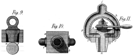
Fig. 9, 10 and 11 of Plate 17, represents one of the forms of this equilibrium Cock. It consists of a square plug case or chamber a b, with a hole c d bored transversely through it, exactly across its centre: and to this chamber is fixed by the flanches e f, the bifurcated water-passage g h, forming one body at i. The plug of this instrument admits of various forms and proportions; of which I have shewn two in the figures 9 and 11. The first m n, receives the fluid through the two openings c d, which correspond, in one position of the plug, with the double water-passage before mentioned. And further, the plug itself is bored lengthwise in its under end n, so as to form the spout of the cock: or otherwise (see fig. 9) this spout is taken in a double form from the outer surface of the plug at b a, so as to present two streams, thus producing, I think, an instrument of somewhat greater solidity. All that seems important is, that whatever be the pressure of the fluid from without, it be made equal on both sides of the plug, so as to occasion no friction between it and the chamber. The principle is indeed so effectual, that one might distribute steam pressure of the greatest strength or even gunpowder pressure, without much resistance to the operator, and without injuring the mechanism by oft repeated action.
OF A MACHINE To communicate and suspend Motion.
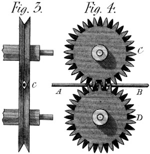
In Plate 19, figs. 3 and 4, shew this mechanism in two directions. It is composed of two wheels C D, cut (or cast) into teeth of a peculiar kind, that both geer with one another, and at the same time, include the chord or round strap A B, by which they are driven. These teeth can be better represented by a figure than in words; and will I suppose be understood from figures 3 and 4: They are divided, on the rim of each wheel by a space too small to admit a tooth of the other wheel: but then, every-other tooth is cut away in a sloping direction on each side of the wheel, from the bottom of the tooth to its top on the opposite side: so that while these teeth are working in each other they offer two grooves, in the form of a V, which coming together surround the chord and press it in four points, either to drive the wheels by the cord, or to pull the chord by the wheels, according to the use it may be wished to make of this mechanism. In fig. 4 the cord is seen at A B, passing among the teeth of the wheels; and in fig. 3 it is shewn at C, as a mere circle, in the centre of a lozenge formed by the teeth whose points now geer together. Fig. 5 is a sketch belonging to this subject, which shews something of the manner of using this round strap as a mover: for by carrying it (either in a horizontal or vertical plane) by a line slightly curved, from one machine to another, it will drive them all and give the means of stopping any one at pleasure. Suppose then, A B C D fig. 5, to be four machines placed as above mentioned. If I wish to stop the machine B, I merely draw back the pressure wheel E, and the cord ceases to lay hold on the machine as shewn by the dotted line: but when I want to set it on again, I do it by bringing back the wheel E to its present position. And thus at a small expence, I could geer a considerable factory, in a way which I think as durable as it appears economical. The principal objection, perhaps, is that this cord is liable to wear out soon, by such incessant action; but then the pressure on it needs not be great; and of friction properly speaking there is very little: Besides which, the cords would be made of a peculiar texture, perhaps of leather, sewed edge to edge and covered like a whip, by one of the machines I shall bring forward hereafter.

It so happens that many of my Inventions are of a generic nature, and thus apply to cases which, appearing different, have nevertheless some common properties. The rule of contraries especially applies to many of them,—of which this is an example. It offers a good method of driving a boat through a tunnel, or other confined space, either by the force of steam or any convenient power. To this end a rope laid along the side of such canal, and fixed at each end, or at several intermediate points, might be led between a pair of wheels like those above described; which duly turned, would drive the boat the distance required with the least possible expence of power, and without the defect of agitating the water.—But I must not anticipate too much on my intended subjects.
OF A MACHINE To set on, and suspend, rapid Motions.
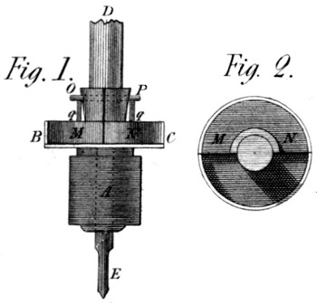
This Invention is under the protection of a Patent. It is applied to the spindles of my spinning machinery called Eagles, from their analogy to the machines named Throstles. It is in my opinion an excellent machine; as it secures a mathematical equality of twist to any number of spindles from permitting the use of geering to turn them, which could not have been done without some means of stopping a single spindle. This mechanism (see Plate 19 fig. 1 and 2) consists of a toothed pinion A soldered to the box B C, (partly cut down in the figure to shew its contents) and with it running loose on the lower part of the spindle E D. In this box are placed two weights M N, like that M fig. 2, which both together, fill the box loosely, and, rising above it, are pinned at O P through the spindle. They are moreover kept from quitting the latter by the ring shewn in section at q q, which holds them loosely, yet prevents their flying away or hurting any one. When now the spindle E D, turns swiftly, the centrifugal force of the two weights M N, projects them from the centre as far as possible; and they lay hold, by friction, of the cylindrical surface of the box B C, and thus keep the revolutions of the spindle to the same number of turns per minute, as the pinion A receives from the driving wheel. But when the spindle is stopped and held by the fly as usual, then the centrifugal force ceases to act, and the box B C does not wear out much, by its further revolutions. And when as before, the spindle is again let loose, that friction which takes place on the bottom of the box sets the spindle running again, when the centrifugal force comes to its aid, so as to unite again the box and the spindle, thus renewing that valuable property of all spinning machinery, the mathematical correctness of its movements.
OF A MACHINE For forging Screws, Beads, &c.
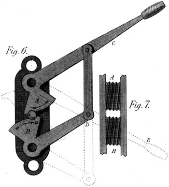
The effect which this Machine is intended to produce, is analogous to several culinary or officinal processes that might be named. It is called rolling: but not in the same sense in which that word is used in manufactories, where rollers form or modify the body acted on. Here this body itself rolls between two surfaces moving different ways and receives from them the desired impressions, and this idea I have extended to screws; proposing to finish them on some metals and in some dimensions; and to rough them out in others. The Machine is represented in figs. 6 and 7 of Plate 19, where fig. 7 shews the faces of the arcs A B of fig. 6. By the form and connection of the arms A C and B D, these arcs move opposite ways: and since they are grooved obliquely as shewn in fig. 7, if a prepared cylinder of soft metal a, be put between them, and the handle C be sharply pressed into the position A E, the cylinder a will be made to roll, and the grooves of fig. 7 be impressed on it so as to meet and form the screw in question. The only conditions are, that the arc B A be at least equal in length to the circumference of the screw, when finished; and that the grooves (fig. 7) be rightly sloped, and have the form intended to be given to the threads of that screw. It will occur of course, that the opening between the arcs at the point where the blank cylinder is introduced, must be larger than the distance between the arcs by the whole depth of the threads to be impressed: which therefore will begin to be formed at two opposite points the moment the screw a begins to roll. This however, might and would be otherwise, if it were thought best to form the arcs A B spirally; and let the deepening process be gradual: in which latter case another consideration would occur, namely; that the grooves themselves (see fig. 7) must diverge a little instead of being parallel, so as to permit the screw to lengthen as the pressure should displace a part of the metal. In all cases the upper surface of the grooves should be milled so as to lay hold of the soft metal, and insure the rolling motion: and should this material be hot-iron, the stroke should be taken in an instant, and the machine be kept cool by every proper method, in the intervals of working.
I need not add that this rolling process would be still easier performed, if the impressions to be made were circular and not oblique: such as beads, balls, &c. but these considerations I leave to my readers.
OF A DIFFERENTIAL STEEL-YARD, To weigh vast Weights with short Levers.
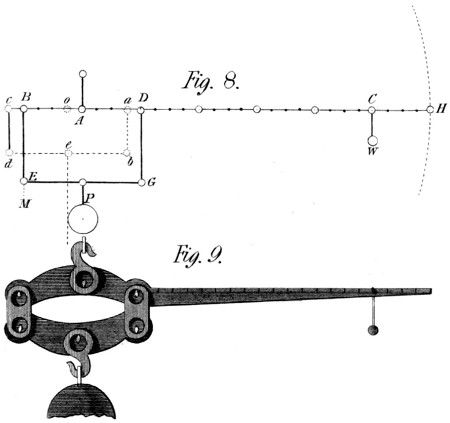
Plate 19, figs. 8 and 9, offers two representations of this Machine—one intended to shew its manner of acting, and the other one of its practical forms. By means of the first, (fig. 8) we may compare it with the common steel-yard; and even shew the latter as a part of the former. If a weight, or load to be weighed M, were suspended to the arm A B, and the counter-weight W, placed at the point C, of the arm A C, we should have a common steel-yard whose power would be as 5 to 1: for the arm A B is just 1⁄5 of the arm A C, and this is the principle on which steel-yards are commonly made. But instead of this, my steel-yard G E B D C H fig. 8, is now infinitely powerful: so much so indeed, as to be infinitely useless. If millions of pounds were now to be suspended at P, they would not raise the weight W one tittle, for they hang entirely on the point of suspension A. But although the Machine is now useless, it can be altered in a moment and made both useful and commodious; only I thought its principle would be the better understood from being thus shewn in excess. To make it a useful and powerful Instrument, I only move the hanging bar D G, to a b; and the bar E B to c d, the lever b d being similar to that E G. In this state of things, the whole load P is found at the point o of the lever B H, (for the lever-arms c o and d e, and those e b, and a o are equal) and the power of this steel-yard is as the line A C to the line A o; that is as 20 to 1, instead of being as 5 to 1 which it before was. But this is not yet a powerful Machine; being chiefly intended to shew the principle on which it acts—and to prove that however small the distance A o, that distance, dividing the arm A C, gives the real power of the steel-yard. And supposing now the arm A C to be four feet in length, and the distance a D, B c, and A o, to be 1⁄10 of an inch, then the power of the weight w to raise (or weigh) the load P is as 48 inches to 1⁄10 of an inch, or as 480 to 1: so that if the weight w were 10lbs. this steel-yard would weigh 4800lbs. or upwards of two tons; and it is easy to see that this power can be almost indefinitely extended.
Fig. 9 of this Plate shews a real steel-yard made on this principle; the power of which, under its present length, is as 40 to 1. In this Machine all the centres are fixed: and the load is suspended on knife-edges, the distances of which from each other and from the common centres are invariable—as they must be in all instruments of this nature.
OF A RETROGRAPH, Or a Machine to write backwards, for Engravers.
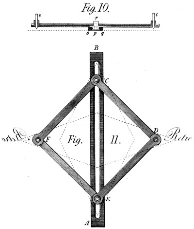
This Machine is exhibited in the two figures 10 and 11 of Plate 19. It is composed of a straight ruler A B, having an exactly dove-tailed mortice made along it, to receive the rollers, (or slides) by means of which the parallelogram C D E F slides up and down in this mortice. This parallelogram is composed of four rulers C D, D E, E F, and F C, connected by cannons or tubes fixed to every-other arm: and on which the contiguous rulers turn very correctly. Through which moreover, in two cases, F D the drawing pencils are introduced, and under which in other two cases, C and E, the guide rollers already mentioned are nicely fixed by the screws on which they turn. This is seen by an elevation in fig. 10, where p marks one of these rollers, and o q the end of the ruler supposed fixed to the paper by proper blunt points, &c. At r is seen one of the tubes which form the joints C and E: and r t, are, one the writing pen, and one the retrographic style or pencil. Fig. 11 is a plan of the whole Machine: where if the hand guiding the pen D goes upward, the tracer F rises too. But if the pen or hand D moves to the right, the tracer moves to the left at the same moment. In a word this is to write backward in the sense of engravers, who thus write that their letters may proceed forward after one impression.
If it were desirable to give the engraver the same facility he has in the use of a pen, the tracer t, fig. 10, would be terminated above as a hollow conical cup, into which he would introduce a pointed style held as a pen. In this case the tracer t, would be made as short or low as possible, to bring the style so much the nearer to the paper; and thus to prevent all anomalous movements.
OF AN EYE MACHINE, Or Machine for making the Eyes of Hooks and Eyes.
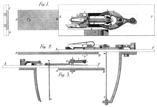
If it were enquired why this Machine is offered to the public without the Hook Machine; the answer would be, this only is finished: and it is wished to present nothing here that admits even a doubt of its utility. The drawings given in Plate 20, figs. 1, 2 and 3, are more intended to be useful in the construction of this Machine than complete in appearance: so that nothing has been done by way of shading, but what it was thought would the better distinguish the parts from each other, and facilitate their assemblage in one effective Machine. The Machine consists first of a slide A B, (worked by a lever-handle, a crank, or any proper first motion.) It glides between two cheeks C D, (see the end view in fig. 1) connected with the several parts about to be mentioned. This slide is marked A B in all the three figures. It carries (by means of the screws a b, coming through the slits c d, in the main Plate E F) a plate g, the chief use of which is to support a tumbler e, whose use is to throw the eye, when made, from the machinery: which tumbler is kept to its work by the spring i, as will be further explained presently. This slide itself has a peculiar form at the end B, (fig. 2) which is shewn by dotted lines at c d in fig. 1. It is a slit, with the corners rounded off for the purpose of working the springs now to be described. These springs m n, (see fig. 2) are fixed to a cock, itself screwed behind the main plate: and they come through the latter to the left-hand-ends of the small curved mortices seen (with the springs) at m n fig. 1. The slide A B then, with its forked end shewn by the dotted lines at c d, is destined to take the springs m n and carry them to r s, where they are now seen surrounded by the eye almost formed: for in this motion these springs take the wire (shewn by the lines dotted across the Machine and previously cut by the sheers u) and meeting with the obstacles t v, being the thicker parts of the clams t v w, they bend it into the form r s—when the screws a b lay hold of the sloping ends of the clams c t w v d, and squeeze them together; by which operation the hooks t v finish the eye, by rolling its two ends round the springs m n now in the position r s. Where note, that the slit c d of the slide A B is so formed as, when it has carried these springs m n to r s, to slide forward without doing any thing more to them, while closing the clams. It performs, however, some other less important operations, to which it is now necessary to allude: among other things this slide works the sheers u that cut the wire, and that, by means of the doubly wedged hook x, which goes back with the plate G, doing nothing: but which by the action of its springs fixed at a, falls under the sloping end of the sheers u; and, when the slide, by the screw b, carries it to the right hand, raises the end x of the sheers u, and cuts the wire near v, to prepare it for the operations already described. The part y in the two figs. 1 and 2, is the other cheek of the sheers fixed by screws to the main plate, and covered by a small plate z, in which a nick is cut to form a passage for the wire, and present it to the sheers, that they may cut it to the proper length, after having directed it right across the springs r s, then placed by their elasticity at m n. It hardly need be added that a stop is placed at o, to determine the length of the wire so as to form the eye complete, and not to admit more wire than is sufficient; all which is regulated between the sheers and the stop, by proper adjusting screws, which it is very easy to suppose or supply.
Fig. 3 is intended chiefly to shew the mechanism by which the eye, when finished, is thrown off the pin round which it is bent by the springs m n. It consists of a tumbler e, placed in a mortice in the end of the plate g, and kept to a given position by the pressure of the spring i. When the slide A B is carried forward, toward E, to perform the operations already noticed, this tumbler e, gives way to the angle G of the doffing lever m G, (this lever being shewn also between c m & d n in fig. 1) and rides towards m without producing any effect either on the plate G or the lever m G: but when it has once passed the said angle G, it cannot go again toward F without depressing smartly the end G of that lever, and thereby raising the end m, thus starting the eye from the stud m, round which it had been bent by the processes above described.
At the right of fig. 1 near F, is an object, the use of which is too evident to need description. It is a double spring for the purpose of keeping the hooks c t w v d pressed against the pins, near t v, which determine the position of the said hooks; and the degree of bend first given to the wire by passing the points t v.
There are some less important parts and operations left undrawn, in order to prevent confusion in the figures: but they are such as would strike any person having the above under his eye. In a word I have done what I thought best to aid the construction of this Instrument:—which is represented at two thirds of its natural size—but whose dimensions, of course, would vary with that of the objects to be produced by it.
OF A VENTILATOR, Rotatory yet by pressure.
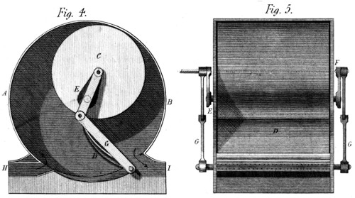
By this title I wish to distinguish this Ventilator from all such as act by the mere centrifugal force of the air: and to make this distinction the more palpable, I would add that this Machine acts like a pump, that is by means of a space alternately contracted and expanded, into which the air enters, and from which it is expelled by force as water is from a pump. The means are the following: A B (fig. 4 of Plate 20) is a hollow cylinder, of a diameter proportioned to the effect wanted to be produced. C is a cylinder closed at both ends, which fills that just mentioned as far as the length goes, excepting a play of about 1⁄8 of an inch. This interior cylinder revolves in the former; but not on its own centre. It revolves on an axis E eccentric to itself, but exactly concentric with the outer cylinder A B. The centre therefore, of the inner cylinder C, describes a circle within the outer one, which is always parallel to its circumference. On the axis of motion of this cylinder C, and outside of that A B, are fixed two cranks E F fig. 5, which exactly reach from its centre of motion to its centre of figure: so that whatever circle the latter describes in the large cylinder, the former describe the same line without it. And hence any slide or valve D, driven by these cranks, will always touch, or be equally near, the circumference of that interior cylinder C. The valve D then, worked by the bars G from without, forms a constant separation between the right and left hand parts of the lunular space left between the fixed and moveable cylinders; and if the latter turns from C by B to D, the right hand space C B G is the plenum, and the left hand space C A D is the vacuum of this Instrument; or in other words the air will flow in, through the passage H, and flow out through the passage I: and by a contrary motion of C, it would do the contrary—but I prefer the first process because any pressure within the valve D is not liable, then, to press the valve upon the drum C, and produce contact and friction; which in the second case it might do. Suffice it to add, that the quantity of air displaced at each revolution of C round its centre of motion, is the difference between the area of the drum C and that of the cylinder A B: and that its quantity at each part of the revolution is proportionate to the curvilinear triangle G B, multiplied by the length of either cylinder.
In the prospectus, this Machine was said to be good as “a gas meter,” which I still think it is. For such a purpose however, friction and eccentricity of weight should be obviated, by placing the axis E, in a perpendicular position: when I doubt not it would measure flowing gas better than many of the machines that have been proposed for that purpose.
OF A COMBINATION OF WHEELS To raise Water.
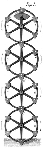
This mode of raising water in its simplicity, is I think called the Persian wheel. The buckets hang upon centres, dip in the under water, fill themselves there, and by meeting an obstacle above which turns the buckets aside, they empty themselves into the upper back, from which the water is conveyed to the general reservoir prepared for it. This present Machine is such an extension of the above principle as to make it applicable to considerable degrees of elevation, and to many situations where a single wheel would be of no service. Having observed that in every train of wheels, the circumferences of any two wheels, have motions towards each other, as well as from each other; I perceived that, in a vertical train, this circumstance might be laid hold of to compose a machine for raising water. Be therefore, (Plate 21, fig. 1) A B C D four of a set of wheels thus intended: on the left of the lowest wheel the buckets move upward, as indicated by the arrow; while those at B move downward, coming thus to meet the former. The buckets A are full, and those B are empty; and as the latter, by the motions of the equal toothed wheels on which they are hung will infallibly meet the former, and even plunge into them at I K and L, it is only to put a clack of leather or a valve, in the bottom of all the buckets, and we have a machine that will raise water to the top-most wheel, be it ever so high, and there the water will be poured out into the vessel M, as in the common Persian wheel above alluded to. On this principle the first change of buckets will take place at I; where the lower bucket belonging to the wheel B G will take the water from the upper bucket of the wheel A H; when the bucket I will go down, nearly empty, by H and fill itself again in the under water; But the bucket of the wheel B G having now got the water, will rise by G to K, where another bucket belonging to the wheel C F will come empty, and plunging itself into that, take its water and go upward by way of C to L, where a similar change will take place and the water from L will rise by E to M, into which vessel it will be poured by the canting of the bucket as seen in the figure. Thus it appears that any number of toothed wheels geering together, surrounded with buckets valved at bottom, and receiving power from any one of their number, will raise simply and effectually a quantity of water not small in proportion to the power employed, and by means that promise great durability to the Machine.
OF AN ECCENTRIC BAR PRESS, For clearing wetted goods of Water.
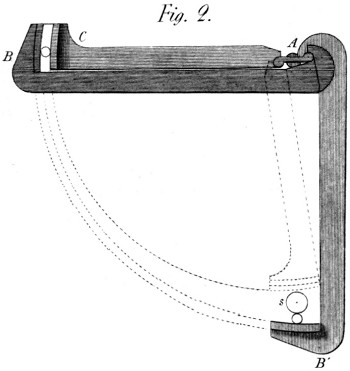
This press (see Plate 21, fig. 2) is indefinitely powerful. It was invented for the use of my late beloved brother, then contractor with government for cleansing the sea bedding. It is composed of a centre piece A, strongly fixed to a post in the ground, the bars A B A C being suspended above it, so as to remain horizontally moveable, while describing 1⁄4 of a revolution round the general centre A. The blankets (or other goods) are put into the space s, (on a net nailed under the bars) while in the position A B; and the whole is then thrown with force towards B C; the length A C being so calculated as to cease pressing at the desired moment: for such is the power of this Machine, even without this projectile force, that were the stress not moderated, nothing could remain whole under its operation. It is clear however, that, when this operation begins at s, the relative motion of the jaws s and B is assignable, and even visible, as shewn by the dotted circles; but as the whole approaches toward B C that relative motion becomes insensible, the circles parallel, and consequently the power infinite: which is all I shall say on the theory of this Machine.
OF A COLOUR MILL, For Calico Printers.
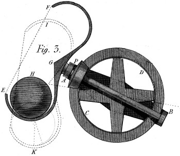
This Machine is delineated in fig. 3 of Plate 21. It has several properties which I think important in the process of grinding colours, either in a wet state or a dry. It consists of a frame A B, which has a hollow centre, through which the axis of the bevel wheel C D is brought in such manner as to geer with the bevel pinion P, in whatever position the frame A B may be placed. The axis of the pinion P carries a vessel of which E F G is a section, and in which rolls a well turned and heavy ball H, upon the colour to be ground: which it crushes in the line of direction of its centre, and to a greater or lesser width according to the diameter of the ball, as compared with the section of the groove E G, in which it rolls. Now as the motion of the vessel E G F, is oblique to the perpendicular, the contact between it and the ball does not take place in any great circle of the latter: but is constantly varying by a twist in its motion dependent upon the angle of the vessel’s inclination to the horizon. From hence arises the impossibility of any colour remaining on the ball unground: and in order likewise, that none may remain uncrushed in any part of the vessel E F G, the frame A B gives it constantly new positions, one of which is represented by the dotted lines I K: where it is seen that the ball bears on a different line of the vessel’s bottom than it did before. This also adds still greater change of action to the ball itself, and occasions (taking both these properties together) an unbounded variety of effect, which necessarily brings every particle of colour under the ball by the mere continuance of motion: and thus grinds it all without any care on the part of the attendants. It may be added, that this vibrating motion of the frame A B, is easily made to result from an eccentric stud and proper connecting rods behind the frame; all which is too easy to require further description.
OF A DYNAMOMETER, Or a second Machine to measure power & resistance in motion.
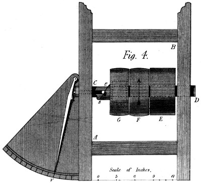
In Plate 21 fig. 4, there is a representation of this Instrument. It is composed of a frame A B, containing a strong shaft C D, on which are placed the three following objects. First, a fixed pulley E, working by a strap, the Machine whose resistance is to be measured. 2ndly, a loose pulley F, receiving the power from the mover whatever it be. And 3rdly, a barrel G, which is the acting pulley, when the strap is put on it from F in the common method. But this barrel G acts by means of a barrel-spring within it, which is hooked by one end to the boss of the shaft, and the other to the rim of the barrel, as is usual for barrel-springs in general. Now the power produces the desired motion by coiling this spring to the necessary degree: and to make that degree visible, there is fixed to this barrel G a spiral s, which as the spring bends, drives outward the stud t, and with it the finger v, which, pointing to the graduated scale, shews at once the number of pounds with which the spring acts on the shaft C D to turn it. By these means the stress on the straps and on the Machine turned is known; of which also the velocity is easily determined by counting the number of revolutions performed by either of the pulleys E F G, which are alike in diameter.
In ending the first part of this work, I gave my readers room to expect this part “within three months,” and am happy now to fulfil that engagement. Although these pages contain fewer errors than the former—an apology is due for those that have crept in: to which I add the promise that every thing shall be done to lessen them further in the future parts, and wholly to correct them before the work closes.
Page 100, line 2, for “:”, read ∷;
„ 126, „ 4, „ “on its surface” read at its pitch line.
„ 126, „ 17, „ “its height f g,” read the length required.
„ 129, „ 16, „ “2,” read 4,
„ „ „ 20, „ “imperfect,” read homely.
„ 144, „ 7, take away “alone.”
„ „ „ 8, for “usually” read chiefly.
„ 146, „ 23, for “the friction,” read it.
„ 147, „ 1, for “nothing,” read little or nothing.
In fig. 7 of Plate 19, slope the groove of both faces the same way.
A few words seem wanting to complete the description of the Cutting Engine above given. They relate principally to the cutter-frame and cutters. Although, with a view to celerity, I have shewn the cutter out of the frame (fig. 4) yet a common frame, carrying the arbor on points, may be used with propriety; and would often be an eligible substitute for the frame above described. In cutting bevel wheels however, either on this Machine or that to be described, there is a form of the cutter frame which leaves less freedom of choice, as the cutter itself must have a peculiar form and position. To return to the cutter for spur wheels, their form (or section) depends on the degree of finish which the wheels require. For rough work they may be cylindrical on the face, the sides being under cut, so as to leave them thickest at the circumference—whence a certain coarseness of cut ensues, but without any injury to the spiral form. But, generally speaking, the cutters are best, when made a little tapering towards the edge, and toothed on both sides as well as on the circumference. The teeth should be tolerably fine, but not very so, unless great smoothness of surface were required: and we have seen above that, in this System, great smoothness is very seldom necessary, provided the obliquities be correct. I may add, that those cutters used on common engines, whose great rapidity compensates for the small number of their teeth, would not answer here, on account of the twisting motion in the wheel. But nothing prevents using cutters, so formed on the sides, as to round off the teeth in the act of cutting—only the cutter must be so thin as that its thickness, added to the aforesaid twist, may not make the spaces too wide. A little observation will render these things familiar to an attentive observer: nor shall this work conclude before all that I have gathered from long observation on this subject, be fully known to my readers.
J. W.
5, Bedford-street, Chorlton Row, 20th. November, 1822.