PART SECOND.
Reading edition
A NEW CENTURY OF
Inventions.
INTRODUCTION.
In the progress of a work like the present, no competent reason could have been assigned for omitting to bring forward my System of Toothed Wheels, the Patent for which has lately expired:—a System which a few years ago, excited in this town, so much interest, aroused so much animosity, and was treated with so much illiberality:—But which, also, was fostered with so much public spirit, tried with so much candour, and adopted with so much confidence. It was I say, incumbent on me to bring the merits of this System into public view, had it only been to justify myself for proposing, and my friends for adopting it. But stronger reasons point now to the same measure. From the intimate connection the System holds with the subjects of this essay, it must be often adverted to; and I have been already obliged to speak of it in terms which can hardly have been understood by those readers who had not previously considered the general Subject. I should therefore be still in danger of filling these Pages with unintelligible assertions, did I not begin by marking out the foundations on which my statements are built; or by explaining to a certain degree, the Principles of the new System. Without then abandoning the tacit engagement I have taken with my unlearned readers—not to entangle them in too much theory, I think it indispensable to quote the Memoir I read before the Literary and Philosophical Society of Manchester, in December, 1815; which small work will form the basis of the practical remarks I shall have to make on the subject, as this work proceeds. The Memoir is thus introduced in the transactions of that learned body:
MEMOIR ON A NEW SYSTEM OF COG OR TOOTHED WHEELS,
By Mr. James White, Engineer.[1]
COMMUNICATED BY T. JARROLD, M. D.
(Read December 29th, 1815.)
“The subject of this paper, though merely of a mechanical nature, cannot fail to interest the Philosophical Society of a town like Manchester, so eminently distinguished for the practice of mechanical science; unless as I fear may be the case, my want of sufficient theoretic knowledge or of perspicuity in the explication, should render my communication not completely intelligible. To be convinced of the importance of the subject, we need only reflect on the vast number of toothed wheels that are daily revolving in this active and populous district, and on the share which they take in the quantity and value of its productions; and it is obvious that any invention tending to divest these instruments of their imperfections, whether it be by lessening their expence, prolonging their duration, or diminishing their friction, must have a beneficial influence on the general prosperity. Now I apprehend that all these ends will be obtained in a greater or less degree, by having wheels formed upon the new system.
I shall not content myself by proving the above theoretically, but shall present the society with wheels, the nature of which is to turn each other in perfect silence, while the friction and wear of their teeth, if any exist, are so small as to elude computation, and which communicate the greatest known velocity without shaking, and by a steady and uniform pressure.
Before I proceed to the particular description of my own wheels, I shall point out one striking defect of the system now in use, without reverting to the period when mechanical tools and operations were greatly inferior to those of modern times. Practical mechanics of late, especially in Britain, have accidentally hit upon better forms and proportions for wheels than were formerly used; whilst the theoretic mechanic, from the time of De la Hire, (about a century ago) has uniformly taught that the true form of the teeth of wheels depends upon the curve called an epicycloid, and that of teeth destined to work in a straight rack depends upon the simple cycloid. The cycloid is a curve which may be formed by the trace of a nail in the circumference of a cart wheel, during the period of one revolution of the wheel, or from the nail’s leaving the ground to its return; and the epicycloid is a curve that may be formed by the trace of a nail, in the circumference of a wheel, which wheel rolls (without sliding) along the circumference of another wheel.
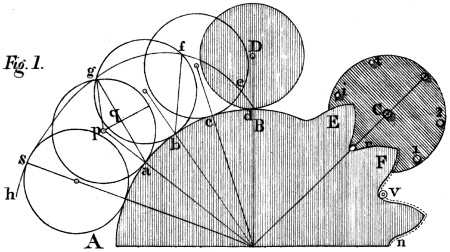
Let A B (Plate 13, fig. 1.) be part of the circumference of a wheel A B F to which it is designed to adapt teeth, so formed as to produce equable motion in the wheel C, when that of the wheel A B F is also equable. Also, let the teeth so formed, act upon the indefinitely small pins r, i, t, let into the plane of the wheel C, near its circumference. To give the teeth of the wheel A B F a proper form, (according to the present prevailing system) a style or pencil may be fixed in the circumference of a circle D equal to the wheel C, and a paper may be placed behind both circles, on which by the rolling of the circle D on A B, will be traced the epicycloid d, e, f, g, s, h, of which the circle A B F is called the base, and D the generating circle. Thus then the wheel to which the teeth are to belong is the base of the curve, and the wheel to be acted upon is the generating circle; but it must be understood that those wheels are not estimated in this description at their extreme diameters, but at a distance from their circumferences sufficient to admit of the necessary penetration of the teeth; or, as M. Camus terms it, where the primitive circles of the wheels touch each other, which is in what is called in this country the pitch line.
Now it has been long demonstrated by mathematicians, that teeth constructed as above would impart equable motion to wheels, supposing the pins, r, i, t, &c. indefinitely small. This point therefore need not be farther insisted upon.
So far the theoretic view is clear; but when we come to practice, the pins r, i, t, previously conceived to be indefinitely small, must have strength, and consequently a considerable diameter, as represented at 1, 2; hence we must take away from the area of the curve a breadth as at v and n = to the semidiameter of the pins, and then equable motion will continue to be produced as before. But it is known to mathematicians that the curve so modified will no longer be strictly an epicycloid; and it was on this account that I was careful above, to say that the teeth of wheels producing equable motion, depended upon that curve; for if the curve of the teeth be a true epicycloid in the case of thick pins, the motion of the wheels will not be equable.
I purposely omit other interesting circumstances in the application of this beautiful curve to rotatory motion; a curve by which I acknowledge that equable motions can be produced, when the teeth of the ordinary geering are made in this manner. But here is the misfortune:—besides the difficulty of executing teeth in the true theoretical form, (which indeed is seldom attempted), this form cannot continue to exist; and hence it is that the best, the most silent geering becomes at last imperfect, noisy and destructive of the machinery, and especially injurious to its more delicate operations.
The cause of this progressive deterioration may be thus explained: Referring again to fig. 1, we there see the base of the curve A B divided into the equal parts a b, b c, and c d; and observing the passage of the generating circle D, from the origin of the curve at d, to the first division c on the base, we shall find no more than the small portion d e, of the curve developed, whereas a second equal step of the generating circle c b, will extend the curve forward from e to f, a greater distance than the former; while a third equal step a b, will extend the curve from f to g, a distance greater than the last; and the successive increments of the curve will be still greater, as it approaches its summit; yet all these parts correspond to equal advances of the wheel, namely, to the equal parts a b, b c and c d of the base, and to equal ones of rotation of the generating circle. Surely then the parts s g, g f, of the epicycloidal tooth will be worn out sooner than those f e, e d, which are rubbed with so much less velocity than the other, even though the pressure were the same. But the pressure is not the same. For, the line a g is the direction in which the pressure of the curve acts at the point g, and the line p q, is the length of the lever-arm on which that pressure acts, to turn the generating circle on its axis (now supposed to be fixt;) but, as the turning force or rotatory effort of the wheels, is by hypothesis uniform, the pressure at g must be inversely as p q; that is, inversely as the cosine of half the angle of rotation of the generating circle; hence it would be infinite at s, the summit of the curve, when this circle has made a semi-revolution.
Thus it appears that independently of the effects of percussion, the end of an epicycloidal tooth must wear out sooner than any part nearer its base, (and if so, much more it may be supposed of a tooth of another form;) and that when its form is thus changed, the advantage it gave must cease, since nothing in the working of the wheel can afterwards restore the form, or remedy the growing evil.
Having now shewn one great defect in the common system of wheels, I shall proceed to develope the principles of the new system, which may be understood through the medium of the three following propositions.
1. The action of a wheel of the new kind on another with which it works or geers is the same at every moment of its revolution, so that the least possible motion of the circumference of one, generates an exactly equal and similar motion in that of the other.
2. There are but two points, one in each wheel, that necessarily touch each other at the same time, and their contact will always take place indefinitely near the plane that passes through the two axes of the wheels, if the diameters of the latter, at the useful or pressing points are in the exact ratio of their number of teeth respectively; in which case there will be no sensible friction between the points in contact.
3. In consequence of the properties above-mentioned, the epicycloidal or any other form of the teeth, is no longer indispensable; but many different forms may be used, without disturbing the principle of equable motion.
With regard to the demonstration of the first proposition, I must premise an observation of M. Camus on this subject, in his Mechanics, 3d. part, page 306, viz. “if all wheels could have teeth infinitely fine, their geering, which might then be considered as a simple contact, would have the property required, [that of acting uniformly] since we have seen that a wheel and a pinion have the same tangential force, when the motion of one is communicated to the other, by an infinitely small penetration of the particles of their respective circumferences.”
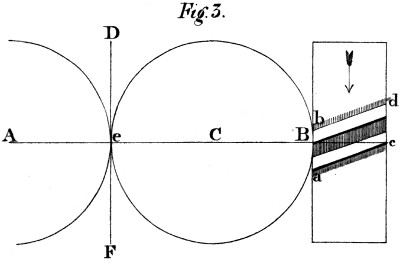
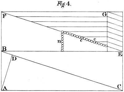
Now suppose that on the cylindrical surface of a spur-wheel B c, (fig. 3) we cut oblique or rather screw-formed teeth, of which two are shewn at a c, b d, so inclined to the plane of the wheel, as that the end c of the tooth a c may not pass the plane of the axes A B c, until the end b of the other tooth b d has arrived at it, this wheel will virtually be divided into an infinite number of teeth, or at least into a number greater than that of the particles of matter, contained in a circular line of the wheel’s circumference. For suppose the surface of a similar, but longer cylinder, stripped from it and stretched on the plane A B C E (fig. 4) where the former oblique line will become the hypothenuse B C, of the right angled triangle C A B, and will represent all the teeth of the given wheel, according to the sketch E G at the bottom of the diagram. Here the lines A B and C E, are equal to the circumference of the base of the cylinder, and A C and B E to its length; and if between A and B, there exist a number, m, of particles of matter, and between A and C a number, n, the whole surfaced A B C E will contain m n particles, or the product of m and n; and the line B C, will contain a number = √m² + n², from a well known theorem; whence it appears that the line B C is necessarily longer than A B, and hence contains more particles of matter.[2]
It is besides evident, that the difference between the lines B C and A B, depends on the angle A C B; in the choice of which, there is a considerable latitude. For general use however, I have chosen an angle of obliquity of 15°, which I shall now assume as the basis of the following calculations. The tangent of 15°, per tables, is in round numbers 268 to radius 1000; and the object now is to find the number of particles in the oblique line B C, when the line A B, contains any other number, t.
By geometry, B C(x) = √r² + t² = √1000² + 268² = 1035 nearly; and this last number is to 268, as the number of particles in the oblique line B C is to the number contained in the circumference A B, of the base of the cylinder. Hence it appears, that a wheel cut into teeth of this form, contains (virtually) about four times as many teeth, as a wheel of the same diameter, but indefinitely thin, would contain. And the disproportion might be increased, by adopting a smaller angle.
Thus I apprehend it is proved, that the action of a wheel of this kind, on another with which it geers, is perfectly uniform in respect of swiftness; and hence the proof that it is likewise so, as to the force communicated.
Before I proceed to the second proposition, I ought perhaps to anticipate some objections that have been made to this system of geering, and which may have already occurred to some gentlemen present. For example, it has been supposed that the friction of these teeth, is augmented by their inclination to the plane of the wheel; but I dare presume to have already proved, that it is this very obliquity, joined to the total absence of motion in direction of the axes, that destroys the friction, instead of creating it. I acknowledge however, that the pressure on the points of contact, is greater than it would be on teeth, parallel to the axes of the wheels, and I farther concede that this pressure tends to displace the wheels in the direction of the axes, (unless this tendency is destroyed by a tooth, with two opposite inclinations.) But supposing this counteraction neglected, let us ascertain the importance of these objections. First, with regard to the increase of pressure on the point D of the line B C, (representing the oblique tooth in question,) relative to that which would be on the line B E, (which represents a tooth of common geering:) let A D be drawn perpendicular to B C. If the point D can slide freely on the line B C, (and this is the most favourable supposition for the objection,) its pressure will be exerted perpendicularly to this line; and if the point A, moves from A to B, the point D, leaving at the same moment the point A, and moving in direction A D, will only arrive at D in the same time, its motion having been slower than that of A, in the proportion of A B to A D; whence by the principle of virtual velocities, its pressure on B C is to that on A C, as the said lines A B to D A.
To convert these pressures into numbers, according to the above data; we have A C = 1000, A B = 268, B C = 1035; then from the similar triangles B A C, B D A, it will be B C : A C ∷ A B : A D = 268000⁄1035 = 259 nearly. Therefore the pressure on B C, is to that on A C, as 268 to 259, or as 1035 : 1000.
To find what part of the force tends to drive the point B, in the direction B E, (for this is what impels the wheels, in the direction of their axes,) we may consider the triangle B A C as an inclined plane, of which B C is the length, and A B the height; and the total pressure on C B, which may be represented by C B, (1035) may be resolved into two others, namely, A B and A C, which will represent the pressures on those lines respectively, (268 and 1000.) Hence the pressure on B C, is augmented only in the ratio of 1035 to 1000, or about 1⁄29 part by the obliquity; and the tendency of the wheels to move in the direction of their axes, (when this angle is used,) is the 268⁄1000 of the original stress, that is, rather more than one quarter. But since the longitudinal motion of an axis can be prevented by a point almost invisible applied to its centre, it follows that the effect of this tendency can be annulled, without any sensible loss of the active power. It may be added, that in vertical axes, those circumstances lose all their importance, since whatever force tends to depress the one and increase its friction, tends equally to elevate the other, and relieve its step of its load; a case that would be made eminently useful, by throwing a larger portion of pressure on the slow-moving axes, and taking it off from the more rapid ones.
We now proceed to the second proposition. The truth of the assertions, contained in this proposition, must, I should suppose, be evident, from the consideration of two circles touching each other, and at the point of contact, coinciding with their common tangent at that point. Let A and B be two circles, tangent to each other, (fig. 3) in e. A C is the line joining the centres, and D F the common tangent of the circles at e; which is at right angles with A C; and so are the circumferences of the two circles at the point e. For the circles and tangent coincide for the moment. Hence then I conclude, 1st that a motion (evanescently small) of the point common to the three lines, can take place without quitting the tangent D F: and 2d. that if there is an infinite number of teeth in these circles, those which are found in the line of the centres, will geer together in preference to those which are out of it, since the latter have the common tangent, and an interval of space between them.
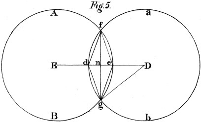
The truth of this proposition (or an indefinite approximation to truth,) may be deduced from the supposition that the two circles do actually penetrate each other. To this end let A B a b, in fig. 5, be two equal circles, placed parallel to each other in two contiguous planes, so as for one to hide the other, in the indefinitely small curvilinear space d f e g. I say that if the arc d g is indefinitely small, the rotation of the two circles will occasion no more friction between the touching surfaces, g e f and f d g, than there would be between the two circles placed in the same plane, and touching at the point n the same common tangent.
For draw the lines D E, f d, d g, g f, g e and g D; and adverting to the known equation of the circle, let d n = x, g n = y and D g = a, the absciss, ordinate and radius of the circle; we have 2 a x - x² = y². From this equation we obtain a = (y² + x²)/2x, the denominator of this fraction (2x) being the width, d e, of the touching surfaces f d g, and f e g of the two circles. But the numerator (y² + x²) is equal to the square of the chord g d of the angle E D g, which chord I shall call z; then we have a = x²/2x from which equation we derive this proportion, a : z ∷ z : 2x = z²/a. But in very small angles, the sines are taken for the arcs without sensible error; and with greater reason may the chords; if then we suppose the arc d g, or the chord z, indefinitely small, we shall find the line d e = 2x = z²/a, indefinitely smaller; that is, of an order of infinitessimals one degree lower; for it is well known that the square of evanescent quantities are indefinitely smaller than the quantities themselves. And to apply this, if the chord z represent the circular distance of two particles of matter found in the screw-formed tooth a c, of the wheel B c, fig. 3, (referred to the circle a b, fig. 5), that distance z will be a mean proportional between the radius D g of such wheel, and the double versed sine of this inconceivably small angle.[3]
I am aware that some mathematicians maintain, that the smallest portion of a curve cannot strictly coincide with a right line; a doctrine which I am not going to impugn. But however this may be, it appears certain that there is no such mathematical curve exhibited in the material world; but only polygons of a greater or less number of sides, according to the density of the various substances, that fall under our observation. I shall therefore proceed to apply the foregoing theory, not indeed to the ultimate particles of matter, (because I do not know their dimensions,) but to those real particles which have been actually measured. Thus, experimental philosophy shews, that a cube of gold of 1⁄2 inch side, may be drawn upon silver to a length of 1442623 feet, and afterwards flattened to a breadth of 1⁄100 of an inch, the two sides of which form a breadth of 1⁄50 of an inch: so that if we divide the above length by 25, we shall have the length of a similar ribbon of metal of 1⁄2 an inch in breadth, namely, 57704 feet; which cut into lengths of 1⁄2 an inch, (or multiplied by 24, the half inches in a foot) give 1384896 such squares, which must constitute the number of laminæ of a half inch cube of gold, or 2769792 for an inch thickness. Let us suppose then a wheel of gold, of two feet in diameter, the friction of whose teeth it is proposed to determine. We must first seek what number of particles are contained in that part of the tooth or teeth, that are found in one inch of the wheel’s circumference; this we have just seen to be 2769792 thicknesses of the leaves, or diameters of the particles, such as we are now contemplating.
We shall now have this proportion, (see fig. 4) 268 (A B) : 1035 (B C) ∷ 2769792 (no. of particles in one inch of circumference of base) : x = 10696771 particles in that part of the line B C, which corresponds with that inch of the circumference. Thus each of the latter particles measured in the direction A B, is equal to the fraction 1⁄10696771ths of an inch. And if that fraction be taken for the arc g d, (fig. 5) then to find the length of the line d e, (on which the friction of this and all other geering depends) we must use this analogy; 12 inch (rad. of wheel) : 1⁄10696771 of an inch (chord g d) ∷ 1⁄10696771 of an inch (g d) : d e, the line required = 1⁄1273050917917292 of an inch. This result is still beyond the truth, as we do not know how much smaller the ultimate molecules of gold are.
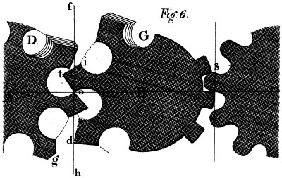
To advert now to some of the practical effects of this system, I would beg leave to present a form of the teeth, the sole working of which would be a sufficient demonstration of the truth of the foregoing theory. A, B, (fig. 6) are two wheels of which the primitive circles or pitch-lines touch each other at o. As all the homologous points of any screw-formed tooth, are at the same distance from the centres of their wheels, I am at liberty to give the teeth a rhomboidal form, o t i; and if the angle o exists all round both wheels, (of which I have attempted graphically to give an idea at D G,) in this case, those particles only which exist in the plane of the tangents f h, &c. and infinitely near that plane passing at right angles to it through the centres A and B, will touch each other; and there, as we have already proved, no sensible motion of the kind producing friction, exists between the points in actual contact. I might add, as the figure evidently indicates, that if any such motion did exist, the angles o would quit each other, and the figure of such teeth become absurd in practice; but on the other hand, if such teeth can exist and work usefully (which I assert they can, nay that all teeth have in this system a tendency to assume that form at the working points;) this circumstance is of itself a practical evidence of the truth of the foregoing theory, and of what I have said concerning it.
It must have been perceived that I have in some degree anticipated the demonstration of my third proposition, namely, that the epicycloidal or any other given form of the teeth, is not essential to this geering. It appears that teeth formed as epicycloids, will become more convex by working; since the base of the curve is the only point where they suffer no diminution by friction; whilst those of every other form, that likewise penetrate beyond the primitive circles of the wheels, will also assume a figure of the same nature, by the rounding off of their points, and the hollowing of the corresponding parts of the teeth they impel; and that operation will continue till an angle similar to that at o, but generally more obtuse, prevails around both wheels; when all sensible change of figure or loss of matter will cease, as the wheels now before you will evince.
On the right of the drawing, (fig. 6) the teeth of the wheel B are angular, (suppose square) and those of the wheel C rounded off by any curve s, within an epicycloid. All that is necessary to remark in this case is, that the teeth of the wheel B must not extend beyond its primitive circle, whilst the round parts of those of the wheel C, do more or less extend beyond its primitive circle; whence it becomes evident, that the contact of such teeth, (if infinite in number) can only take place in the plane of the common tangent at right angles to A B; also that if these teeth are sufficiently hard to withstand ordinary pressure, without indentation in these circumstances, there is no perceptible reason for a sensible change of form; since this contact only takes place where the two motions are alike, both in swiftness and direction. A fact I am going to mention may outweigh this reasoning in the minds of some, but cannot invalidate it. I caused two of these wheels made of brass, to be turned with rapidity under a considerable resistance for several weeks together, keeping them always anointed with oil and emery, one of the most destructive mixtures known for rubbing metals; but after this severe trial, the teeth of the wheels, at their primitive circles were found as entire as before the experiment. And why? Certainly for no other reason than that they worked without sensible friction.
Hitherto nothing has been said of wheels in the conical form, usually denominated mitre and bevel geer. But my models will prove, that they are both comprehended in the system. The only condition of this unity of principle is, that the axes of two wheels, instead of being parallel to each other, be always found in the same plane. With this condition, every property above-mentioned, extends to this class of wheels, which my methods of executing also include, as indeed they do every possible case of geering.
Being afraid of trespassing on the time of the society, I have suppressed a part of this paper, perhaps already too long; but I hope I may be indulged with a few remarks on the application of those wheels to practical purposes. And first, as to what I have myself seen; these wheels have been used in several important machines to which they have given much swiftness, softness or precision of motion as the case required. They have done more; they have given birth to machines of no small importance, that could not have existed without them. In rapid motions they do all that band or cord can perform, with the addition of mathematical exactness, and an important saving of power. In spinning factories these properties must be peculiarly interesting; and in calico-printing, where the various delicate operations require great precision of motion. In clock-making also, this property is of great importance in regulating the action of the weight, and thus giving full scope to the equalizing principle whatever it be. I may add, it almost annuls the cause of anomaly in these machines, since a given clock will go with less than 1⁄4 of the weight usually employed to move it. Another useful application may be mentioned; in flatting mills, where one roller is driven by a pinion from the other, there is a constant combat between the effort of the plate to pass equally through the rollers, and the action of the common geering, which is more or less convulsive. Whence the plate is puckered, and the resistance much increased, both which circumstances these wheels completely obviate; and many similar cases might be adduced.
I shall only add, that my ambition will be highly gratified if, through the approbation of this learned society, I may hope to contribute to the improvement and perfection of the manufactures of this county; and if the invention be found of general utility to my much loved country.”
Subsequently to the reading of the above paper, I had occasion to execute many wheels on this principle; and their appearance, and use, excited on the one hand much interest, and on the other much opposition. I had even to complain of real injury in that contest: against which I defended myself with a warmth that I thought proportionate to the attack.—But all this was local and temporary: and writing now for a more enlarged sphere, and perhaps for a more extended period, I feel inclined to lay aside every consideration, but those immediately connected with the influence of this work on the public prosperity. I shall therefore avoid all reference to the names either of my friends or my opponents. My friends will live in a grateful heart, as long as memory itself shall last; my enemies, if I have any, will be forgiven—or, at worst, forgotten; and my System is henceforward left to wind its way into public notice and usefulness, by its own intrinsic merits.
Certain Observations which I was induced to make on occasion of a re-print of the above Memoir, may assist in introducing what remains to be said on the subject. They commence thus:
The foregoing little work, which first brought this subject into public notice in this town, was not the only method employed to develope its principles, and urge its adoption. A second paper was read, at the next meeting of the society, and some time after, a third, at the Exchange Dining Room; on both which occasions new modes of reasoning were pursued, and new kinds of proof adduced. On the first, a model was exhibited of two screw-formed teeth (connected with proper centres) exactly like those represented in fig. 6; by the action of which on each other, it became manifest that teeth of this angular shape do work together without inconvenience, and therefore, that all sensible friction is, in this case, done away.
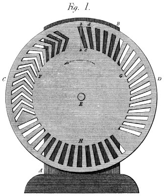
On the latter occasion (the lecture at the Exchange) two other methods were brought forward, to corroborate the principles before stated: (see Plate 14, fig. 1.) The first was a kind of transparency, in which a line of light represented the place of contact of two wheels working together; by the partial and variable obscuration of which, the successive action of every portion of the teeth was clearly shewn. The second method consisted of two pair of wheels, made from loaf sugar, the teeth of which were cut one pair in the usual form, and the other on the new principle. Here, the difference in the effects of the two methods was so great, that the common teeth were almost immediately worn or broken down, by the very same kind of impulse that the new wheels sustained without injury: and with a loss of matter almost imperceptible, since many thousand revolutions of the wheels took place without detaching so many grains of sugar!
These Observations include likewise the following remarks:
In adverting to a few of the difficulties we have encountered, it will appear curious that one of them should spring from a most useful property of the system: but the paradox is thus explained. As there is no method more effectual for giving the teeth a perfect form, than working the wheels together, (covering them with an abrasive substance) we have most frequently chosen to depend on that important property; and have therefore set the wheels at work as they came from the foundry, instead of chipping the teeth, as is usual when common wheels are expected to act well in the first instance. But our wheels being then full of asperities, their action would be of course imperfect and noisy, till time had smoothed and equalized the touching surfaces: a state of things that might well stagger the opinion of a candid observer unacquainted with the system. Happily however we can now appeal to the fact of many wheels having become silent, that were once referred to with triumph, as proofs of a radical defect in the principle. It may not be improper to add here, that if highly finished wheels were particularly desired, we would engage to cut them in metal on this principle, with all the perfection of surface given to common wheels by the first masters.
In the use of bevel wheels of this description (with singly inclined teeth) there is doubtless a tendency to approach toward or recede from each other; the extent of which (for cylindrical wheels) has been already determined. This tendency goes, so far, to give a bend to the shaft; and, if this be very weak, to create a degree of friction on the teeth as the wheels revolve. It is therefore desirable that the shafts should be rather too strong than too weak; since the principle can only exist entire, when the wheels in working, are kept in the same planes which they occupy when at rest. This is too evident to be further insisted on.
But a greater, or at least a more frequent cause of friction in the wheels is the motion, endwise, of the shafts, arising from a want of solidity in the bearers, and especially of connection between them; for whenever these are strongly connected, and the shafts well fitted to their steps, all circular commotion is ipso facto destroyed; while the longitudinal tendency produced by the teeth on the shafts is certainly an advantage: because it prevents the shaking that often arises from their vibration, endwise, when lying on unsteady bearers, or on bearers between which they have too much liberty.
A few words will make known the process of reasoning by which I arrived at the idea that forms the basis of this invention. I had been conferring with a well-known mechanical character, (to whom the art is greatly indebted)—and hearing his observations on the advantage derived from having two equal cog wheels connected together, with the teeth of the one placed opposite the spaces of the other; so as to reduce the pitch one half, and the friction still more; (since the latter follows the ratio of the double versed sines of the half-angles between the teeth respectively:)—and no sooner had I left that gentleman, than my imagination thus whispered—“What that gentleman says is both true and important.” “But if two wheels thus placed, produce so good an effect, three wheels (dividing the original pitch into three), would produce a better: and four, a better still: And five a better than that. And for the same reason, an indefinite number of such wheels would be indefinitely better! We must then cut off the corners of all those teeth, and we shall have one screw-formed line, that will represent an indefinite number of teeth, and approach indefinitely near to absolute perfection!” Thus did this Invention originate: and it soon appeared to me, to be the nearest approach of material exactitude to mathematical precision, that is to be found in the whole circle of practical mechanics. For not only is the relative motion of the touching points of two wheels (that is their friction), less than the distance between two of the nearest particles of matter, but it is as many times less than that distance, as that distance is less than the half diameter of any wheel whose teeth are thus formed.
I assert therefore that these teeth, placed in proper circumstances, do work without sensible friction at their pitch lines: as although by means of mathematical abstraction, it may be possible to assign a degree of friction between them, that degree cannot be realized on a material surface: and I fear not the friction on mathematical surfaces, if my material surfaces do not suffer from it. I take leave then to repeat, that no friction can justly be said to arise from a motion, too short to carry a rubbing particle from one particle of a rubbed surface to the next! and this is precisely the case in the present instance.
Continuing to reflect on this important subject, I soon perceived that the screw-formed line would give the teeth a tendency to slide out of each other; and to drive the shafts of the wheels endwise in opposite directions; but even that evil is not great: for, confining the obliquity within 15 degrees, that tendency is only about one quarter of the useful effort; and a stop acting on the central points of the axes, will annul this tendency without any sensible loss of power. We need not even have recourse to this expedient when any good reason opposes it: for this tendency can be destroyed altogether by using two opposite inclinations: giving the teeth the form of a V on the surface of the wheels—a method which I actually followed on the very first pair I ever executed, which I believe are now in the Conservatory of Arts at Paris.
A circumstance somewhat remarkable deserves to be here noticed. In the specification of a Patent which I have seen in a periodical work since my return from Paris, for things respecting steam engines, and dated, if I recollect right, in 1804 or 5, this V formed tooth is introduced—as an article of the specification, yet having no connection whatever with its other subjects; nor being attended with the most distant allusion to the principle of this geering. The fact is that I had these V wheels in my Portique, in 1801, when that exhibition took place in which my Parallel motion appeared and was rewarded by a Medal from Bonaparte: so that two of my countrymen at least, engineers like myself, appear to have taken occasion from that exhibition, to draw my inventions from France to England—a thing by no means wrong in itself nor displeasing to me: who was then totally precluded from holding any communication of that kind with my native country.
It would be repeating the statements contained in the foregoing memoir, to say more on the general principles of this System. I request therefore, my readers to give that paper an attentive perusal; and to accept the following recapitulation of its contents:
1. To cut teeth of this form in any wheel is, virtually, to divide it into a number of teeth as near to infinite, as the smallness of a material point is to that of a mathematical one.
2. By the use of these teeth, and the multitude of contacts succeeding each other thence arising, all perceptible noise or commotion is prevented. (This of course supposes good execution, or long-continued previous working.)
3. For the same reasons, all sensible abrasion is avoided: for we have proved that the passage of any point of one wheel, over the corresponding point of another, is indefinitely less than the distance between the nearest particles of matter. (This supposes the action confined to the pitch line of the wheel; and this it will be in all common cases—since the teeth wear each other in preference, within and without that line; which therefore must remain prominent.)
4. From the foregoing it appears that the teeth of two wheels working together tend constantly to assume a form more and more perfect: as they abrade each other while imperfect, and cannot wear themselves beyond perfection.
5. For a similar reason the division of the teeth cannot remain unequal: for those that are too far distant from a given tooth will be attacked behind, and those that are too near before; so that the division also will finally become perfect.
But it must be remembered that these recoveries of form are in their nature very slow; since the nearer the teeth come to perfection the slower is their approach to it: so that in thus dwelling on these properties, we do not advise the making of bad wheels that they may become good; but only wish to destroy an honest prejudice that has already much impeded the progress of the System; namely, that it requires great nicety to adjust them so as to work together at all: which is—(to say the least) a very great error.
In Plate 14, fig. 1, I have shewn the apparatus presented at the Exchange, as mentioned in page 110 preceding. A B is the stand; C D is a disk turning on the centre E; b a is the transparent line cut through the stand, and representing the place of contact of two wheels geering together. It is there seen, (supposing the disk to turn in the direction of the arrow) that the action of the teeth, is always progressive along the transparent line a b; whether the single or double obliquity G or F be used. In reality, the lower end of any tooth c, does not uncover the line a b, till the upper point of the succeeding tooth d has begun to cover it; whereas, observing a few of the common teeth represented at H, as directed to the centre of the disk, they would be seen to pass the line a b all at once; and thus to represent, with a certain exaggeration, the transient manner of acting of the common geering.
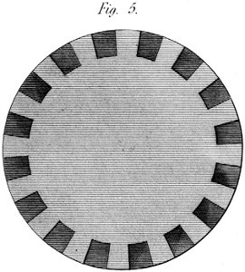
Some knowledge of the nature of this geering may be gathered from its very appearance: see fig. 5 Plate 14. To represent these teeth properly, no light must appear between them. The tops of the teeth offer a continued circular line, similar to what it would be if there were no teeth at all: and the latter are distinguished only by a different shading of their front and lateral surfaces. The reason (as has been already observed) is, that they are necessarily so placed, as that the last end of any tooth shall not quit the plane of the centres, until the first end of the succeeding tooth arrives at it; which principle precludes the possibility of any space remaining between the teeth, that an eye directed parallelly to the axes could penetrate. Such a space indeed would introduce a portion of the properties of the old geering, which it is the object of this System to avoid. As this wheel then appears in fig. 5, so it acts: that is equally and perpetually.
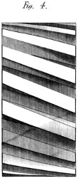
It were well also to observe the appearance of these wheels on their edges; or in the planes which, as wheels they occupy. The 4th. figure of this Plate is outlined with some care, in order to shew the varying, and seemingly anomalous form which the teeth assume as they approach the boundaries of the figure. Although cut as obliquely to the axis there, as any where else, the receding cylindrical surface, thus seen, appears to take this obliquity away; and the very outward teeth seem nearly parallel to the axis of the wheel. But this is only appearance: and we give here one example of it, that we may not be obliged to lose much time hereafter, in drawing correctly, wheels on this principle—a process indeed which in many cases, would be found very difficult, if not impossible.
We have already adverted to the oblique tendencies of these wheels, when used with a single inclination of the teeth; from which, among other things, it follows that, in the act of urging the shafts endwise, they tend also to bend these shafts: for which reason the shafts require to be stronger than those of common wheels—that is, when the effort bears any proportion to their stiffness—a circumstance which, in light rapid movements, is of small moment. And in heavier works, when it is desirable to get rid of these tendencies altogether, we have peremptory means of avoiding the very appearance of this evil.
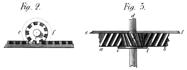
Suppose then (fig. 2 and 3, plate 14) a b to be a straight rack on this principle; driven by the wheel or pinion c. The motion, backward, of the pinion, tends, clearly, to urge the pinion endwise towards d, and the rack sideways towards a b. But either of these motions is prevented by fixing to the pinion, or the rack, a cheek e f, to support them against this lateral pressure. But then, exclaims a doubting friend, you introduce friction: and it is true: there is now a real rubbing of the ends of the teeth against this cheek; but the pressure there being only one quarter of what it would be on the front of straight teeth, we avoid (on a rough estimate) three quarters of the friction; while preserving all the constancy and smoothness of motion which the system gives; and which after all, is the most important part of the business.
This idea then applies among other things to the racks of slide-lathes; giving a regular motion to the rest and cutting tool, thereby adding to the perfection of the turning process: and many other cases might be adduced.
But instead of using a rack and pinion, as thus described, two wheels, of any desired proportions might have been thus treated, and the result would have been the same. They would have worked with perfect smoothness, under about one quarter of the friction attendant upon common wheels in similar circumstances. There are cases therefore, in which it would be expedient thus to employ the System. I cannot but observe likewise, that this method of using cheeks to prevent any side motion in spur wheels, might also be applied to bevel-wheels, to prevent the angular tendency which the obliquity of their teeth gives them: and that I prefer such a method of obviating this evil (where it is one) to any attempt at using teeth in the V form, on bevel wheels. Still however, as before observed, this counteraction of the oblique tendencies is not always necessary. It may be dispensed with in all light and rapid movements; especially in the use of perpendicular shafts; and where the driven wheels are small and distributed round a central wheel in positions nearly opposite each other: of all which cases we shall see examples in the spinning machinery to be described hereafter.
OF THE CUTTING ENGINE, To form Spur-wheels, on my late Patent principle.
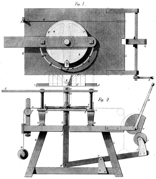
The figures of this Engine (see Plates 15 and 16,) are drawn to a scale, from the Machine itself, now before me. The scale of the objects on Plate 15, is one inch and three quarters to the foot; and that of the objects on Plate 16, one inch and one third. These were convenient proportions for introducing this object into the present work; but the size itself of the Machine is arbitrary. I did not make it according to my ideas of the best dimensions: but bought it as a common cutting Engine, and gave it those other properties that my System required.
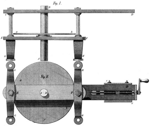
The first remarkable deviation from the usual form is in the shaft or axis of the dividing plate. See fig. 1 and 2 of the Plates 15 and 16. The dividing plate a b, is concentric with, and fixed to an axis A B made as perfectly cylindrical as possible, so as both to slide and turn in the bars C D, and E F composing the frame. These bars are bushed, to fit the axis A B, either with a contracting ring of brass, as usual in some mathematical instruments; or with type metal, cast around the axis into rough holes in those bars:—which metal, closing upon the axis makes a good centre; and will last a long time. My Engine is made in this manner; and has been renewed in this part only twice in several years. This frame C D E F of the Engine, is strongly connected with the feet G G H H, by means of the nuts E F in the plan: and by these feet it is fixed to its bench or table, as will be seen in Plate 16.
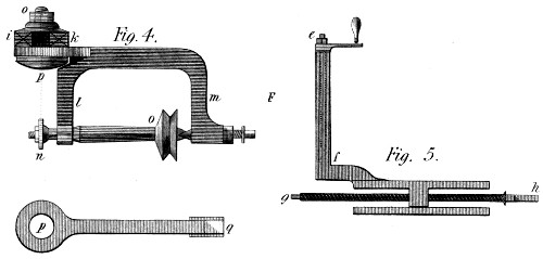
Figure 2 of the present Plate, represents the plan of the Machine, but turned upside down; so that the feet G H screwed under the lower plate E F, are wholly visible. In this figure, also, is shewn at c d, the edges (without the bottom) of the horizontal slide which carries the stand for the cutter frame represented in fig. 4. This stand is indicated by the dotted lines of this figure 2, as situated under the arm D of the bar C D; but it is better shewn in fig. 5, where e f marks the slide in which the cutter frame (fig. 4) moves up and down, by means of the screw and handle e f. In general I avoid dwelling much on these smaller parts, because they exist, probably in a more perfect state, in most other machines. In this fig. 5, g h shews the screw that moves this stand nearer to, or further from the axis A B of the Engine, according to the diameter of the wheels: which is also a common process in Machines of this kind, on which therefore much need not be said. But a somewhat greater importance attaches to the cutter frame represented in the 4th. figure: which is a kind of small lathe whose spindle n o, carries the cutter n, outside the frame, for the purpose of changing the former without displacing the latter. The cutter (of any proper section) is placed in or near that line which is a continuation of the centre of the fixing screw o p. It is in that line for wheels whose teeth can be finished with once cutting: but near it for those whose teeth must be cut at twice. In this same figure, i k represent the ends of the standards that form the vertical slide e f of fig. 5; and the separate figure p q, shews the back of the cutter frame l m, the flat part of which, p, presses correctly on these uprights i k, and thus fixes this instrument at any desired height, and to any given angle with the perpendicular: the use of which arrangement we shall soon have occasion to exemplify.
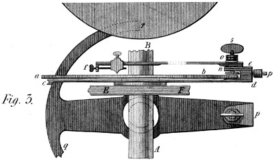
Turning now to fig. 3 of this Plate, we there see the main shaft A B, broken off at B: and the letters a b again shew the dividing plate of figs. 1 and 2: under this Plate is seen an alidade or moveable index, shewn by section only at c, and in elevation at d e; where it clips the plate as far as n and carries a boss between n and e, on which the dividing index e f, turns; and to which it is strongly fixed by a nut o, when the proper number to be cut is determined. Moreover, this boss forms, itself, the nut of a thumb-screw s, which, carrying a circular plate at its lower end, clothed with leather or any soft substance, connects strongly, without injuring the plate, the moveable index with any point of it, as determined by the dividing index e f. This brings us into the midst of things, as it respects the use of this Engine; for the former index c d, is furnished with a small roller, p, the motion of which all the foregoing objects must obey, when they have been fastened together by the thumb-screw s. We turn then to the figures 1 and 2 of Plate 16, in order to shew those parts in action: after remarking only that the form p q r of this fig. 3, is that of the moveable index shewn before at c d; requiring only, to become complete, that the part q should be sufficiently lengthened to make the arc r q a complete semi-circle—for purposes that will shortly be explained.
In the two figures of Plate 16, the Machine is shewn as placed on its bench or table, accompanied by the parts which give it a distinctive character, and in fact embody the System. In addition to the parts already described, we first remark the circular rim c d, fixed to the ends of the bar E F; and made perfectly concentric with the main shaft A B, and the dividing plate a b. This rim is shewn in section only, at v fig. 2. Its section resembles an L, and thus forms a basis for certain plates that will soon appear; and receives the screws by which these plates are fastened to it. This being sufficiently clear, we now proceed to describe the table and the connection of its mechanism with the foregoing.
In Plate 16, K L is the table: to which the Engine is screwed through its feet G H. I, is a square bar of wood, sliding in a mortice through the top of the table; and connected by a joint with the lever M N—itself moving round a pin at O, and carrying a friction roller, P, which pressed by the spiral Q, as turned by the handle R, raises the bar I, and with it the main axis A B of the plate, and of course the wheel to be cut, centered as usual on this axis above B. Finally, p q r, in both figures, is the moveable index first shewn in fig. 3 of Plate 15; prepared to be drawn round by a weight W, hanging to the cord x, passing over the pulley y, and tied to the right end of the arc q r, when this is to move to the left; or to its left end, when the motion is to be toward the right:—these motions depending on the right or left-handed direction of the teeth which it might be wished to cut on the Machine.
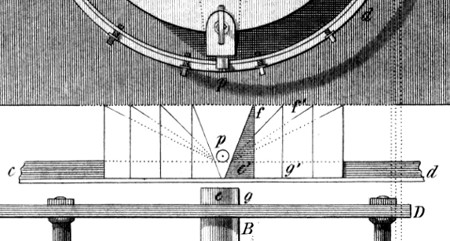
Between the two figures 1 and 2 of this Plate, there appears a diagram, the base of which is nothing more than a part of the rim c d supposed straightened, and placed there that its use may be the easier understood. On the rim is seen a right angled triangle e g f, against which the roller p will lean by the action of the weight W on the cord x, and the arc q r of the moving index p q r. So THAT when, by the handle R, the spiral Q depresses the lever M N, by means of its roller P, then the bar I raises the axis A B of the Engine, and the weight W turns it at the same time, as much as the small roller p permits by rolling up the side e f of the plate e g f. And thus may a screw-formed tooth be cut in any wheel centered above B in the usual manner.
Thus then, in describing this Machine, the manner of using it has been also shewn: for the cutter, in this Machine, (to cut spur wheels) is always fixed; and all the motion is composed of the rotatory and longitudinal movements of the principal axis, which carries the wheel along with it. The cutter I say is fixed, at a proper height just above the wheel, and at an angle to the perpendicular, equal to that it is wished the teeth should form at it’s pitch line. This inclination as before observed is 15 degrees; and the tangent of 15° is in round numbers 268, when the radius is 1000. That is, in our present figure, the basis e g of the plate e g f, occupies 268 divisions of a scale, of which the height g f contains 1000. It appears then, that to cut a tooth with 15 degrees inclination, by this Plate, the wheel receiving that tooth, must be just as large as the rim itself; for the surface of the wheel would turn more, with a given elevation, if it were larger than the rim; and would turn less, by the same elevation, if it were smaller. In a word the whole theory of this operation, is now clearly seen. The smaller the wheel to be cut, the longer, horizontally, must be the Plate; or in other words, as the diameter of the wheel is to that of the rim, (c d) so is the length e g of the Plate to the length required. Now this height f g, is always the same; all change therefore, in the plates, takes place on the horizontal length: and this length is most easily found by the foregoing RULE OF THREE. If then, instead of the triangle e f g, I had used the triangle e′ f′ g′ it would have followed at once, that to produce an inclination of 15 degrees, I must have taken a wheel of just half the diameter of the rim; for the plate e′ f′ g′ is just twice as long as that e f g. To prove this, let us suppose the diameter of a wheel wanted, to equal one half that of the rim c d: then the rule will stand thus:
1 is to 2, as 268 is to ...536, the length of the plate according to the theory; which is precisely the length it is drawn to compared with that e f g, namely twice as long. Thus the four triangles, drawn to the right and left in this diagram, represent the plates for the wheels of the following diameters respectively:
No. 1 , a wheel equal to the plate rim c d;
2 do. do. to 1⁄2 do.
3 do. do. to 1⁄3 do.
4 do. do. to 1⁄4 do.
A small anomaly, of form, may be mentioned here to prevent mistakes. The shaded triangle e f g in the Plate, looks higher than the rest: but if higher, it is also longer in the same proportion; and the roller p never reaches the bottom: so that the effect of this Plate is the same as though it resembled the others in every respect. In general the effect of the Plates depends on their length compared with their height: and indeed they must be made higher than the thickness of the wheel to be cut, that the latter may disengage itself from the (fixed) cutter both above and below.
It is proper to observe, that for every pair of wheels there must be a pair of plates; one leaning to the right and the other to the left, (see the diagram) but, as before said, the degree of obliquity must be different in each pair, except in the case of equal wheels, when the same plate serves for both; only turning it to the right for one wheel, and to the left for the other. Nor does this offer any difficulty, as the plates are made of common tin plate: which is easily brought to fit the rim, whichever way it is applied. I shall now add another example of the process for finding the length of the plates: and to that end repeat that the plate rim c d, is 22 inches in diameter, or 11 inches radius. Supposing then that we wished to cut a pair of wheels, one of them being 1 inch in diameter and the other 12 inches; both to have teeth inclined 15 degrees to the axes; (as without that they could not work together) to do this we must effect these two proportions:
(1) 1⁄2 inch (radius of small wheel) is to 11 inches, (radius of plate rim) as 268 parts (of which the height of the plate is 1000) to another number, which is the length of the plate sought: measured on a scale of parts of the same magnitude.
(2) 6 inches, radius of the large wheel; is to 11 inches radius of plate rim; as 268 parts (as before) is to another number, which is the length sought for this second plate.
Both proportions being effected, the first plate is 5896 parts.
And the second 491.33 do.
The one of course, to be directed toward the right hand, and the other toward the left, on the plate rim; where note, that if the height (1000 parts) is found so numerous as to create confusion, let 100 parts be assumed; when the length of the plate will become 26.8 or 26 and 8⁄10 instead of 268, and the operation will be so much the more simple.
It should be added that this process admits of being further simplified: since the product of 11 inches, radius of the plate rim, multiplied by 268 (tangent of 15 degrees, or length of the plate for a wheel equal in diameter to the plate rim) since this product, I say, is a constant number, namely: 2948—which, divided by the half diameter of any wheel, gives, at once the length of the plate adapted to that operation, in parts of which the height contains 1000; or supposing the height to be 100 only, this constant number becomes (nearly enough for practice) 295. In a word, on a height of plate of 100 parts, when wishing to cut a wheel of 4 inches in diameter, I merely divide 295 by 2, and get for the length of my plate 147.5 parts of which the aforesaid height is 100.
It may possibly be suggested that this method of using plates to determine the obliquity of the teeth is a homely method, giving some trouble in the execution, and leaving a certain degree of roughness in that execution. The fact is allowed; but this method has the advantage of a very general application, which many a better looking apparatus would not present.
Besides, for most uses, these teeth require chiefly that the obliquity should be correct, and not that the surface should be licked like those of a gewgaw. In fine, the principle of this Machine once known, its best form will occur to the reflecting mechanician according to the quality of the work he has in view: And in fact, in the hands of a well known artist, this form has been already varied so as to produce effects much higher wrought than could be drawn from the Machine above described: which latter however in point of generality, still preserves the advantage.
OF A DOOR-SPRING, To keep a Door strongly closed, yet suffer it to be opened easily.
That “necessity is the mother of invention,” is a remark none the less true, for having become a trite proverb; I could mention the time, place, and circumstance which gave birth to this little Invention: but such detail would be superfluous. A certain door was, and is still, most inconvenient, from the stiffness of the spring, and the noise it occasions in a place where silence ought to prevail: which state of things suggested to my mind the Machine represented in fig. 5, of plate 17.
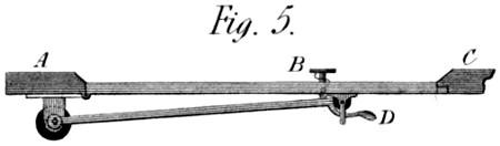
A B C in that Plate, is a horizontal section of the door, door jambs, &c. The door spring now in use, is a barrel-spring, with an arm carrying a small roller which presses in a gutter-formed plate, screwed to the door. My door spring is on a different principle. The roller is fastened in and by a small frame to the door, and the arm is fixed to the axis of the spring, which passes up through the top of the barrel. This spring is much weaker than the former, insomuch as only just to close the door by its elasticity; but when the door is shut, there is a sharp bend in the arm that wedges itself against the roller, and decuples at least the force of the spring, as tending to keep the door closed. When therefore it is desired to open the door, by pressing the door itself, a good push is necessary, but only for an instant: for as soon as the bent part of the arm is forced off the roller, there remains only the small resistance of the spring to be overcome; which latter, when suffered to act in shutting the door, will not shut it with that noise a stronger spring would occasion; and yet, when arrived at its first position, it will keep the door as strongly closed as ever. And should it be wished to avoid the necessity of pushing hard against the door, even at first, there is a sliding button and stem B put through it, which, if pressed from the other side, with the force only of the spring, will raise the latter beyond the roller, and thus open the door with perfect facility: and this same process will take place in pulling the door open by the hook D from the inside: yet still the door when closed will be as firmly so as before; the spring-bar acting in the latter position, as much like an invincible stay as the workman shall have desired—this property depending clearly on the nearness of the bend to a right angle.
This device may appear to some an object too inconsiderable to be justly dignified with the name of an invention. But if I should sometimes fall into such an error as this, I intend to compensate for any thing too trivial by giving in other cases, Inventions of ample size and number. I might even mention the Cutting Engine given in this part, where several Inventions are compressed into one, or rather presented as one, of which several examples will occur.
OF A DRAW-BENCH, For making my twisted Pinions.
The pinion wire of clock and watch makers is well known. I am not wholly acquainted with the manner in which it is drawn: but I have made my pinion wire, of brass, in lengths of about a foot, by the Machine described below.
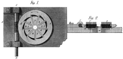
A common Draw-bench (not here represented) is worked in the usual manner: but the instrument which forms the pinion (see Plate 17, fig. 1) is of a peculiar construction. It consists of a plate A B, containing—1st. a guide tube a, (fig. 2) to centre and conduct the blank wire;—2d. a ring b c, with nine grooves cut on one of its surfaces, directed to the centre, and in which are well fitted the cutters 1 2 3 4 5 6 7 8 9; and 3d. a ring d e, formed into nine spirals exactly like each other, answering to the cutters, and destined to urge them equally toward the common centre whenever this circle d e, is turned by the endless screw C D, in the direction of the arrow. In fig. 2, f g is merely a top piece to cover at the same time the cutters and the ring d e; which latter is thus duly centered. The points of the cutters 1, 2, 3, &c. are formed like the spaces of pinion teeth; and in the other direction, are sloped 15 degrees to the common axis, as taken at their pitch line.
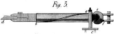
The third figure represents the drawing clams, or pinchers, with a piece of blank wire d in them, tapered off to give easy entrance to the cutters. These clams have a cylindrical part of about a foot long, in which is cut a winding groove a b, whose use is to turn the wire in the act of drawing; for which purpose also the swivel e f is provided. The method I employ to trace this groove to the obliquity required, is to measure the circumference of the cylinder, and call that 268; and then, to make its length, in the cylindrical part, equal to 1000 of the same divisions. But this is right, only when the pinion to be drawn is of equal diameter with the clam-cylinder a b: so that if it is wished to draw pinions of a smaller diameter, I further say: diameter of clam-cylinder is to diameter of pinion, at the pitch line; As 1000 (present length of clam-cylinder) is to required length of ditto. Thus, for example, if the diameter of the pinion were only 1⁄4 that of the clam-cylinder, the length of the latter would be only 250 of the 1000 divisions, before found: and so in proportion for smaller diameters.
The figure shews this groove receiving a guide screw or stud a, which, placed in the fixed headstock a c, turns the clams d, with the wire, just enough to give the teeth an inclination of 15 degrees, thus adapting them to the wheels of which the proportions have been already given; where note, that the real dimensions of this pinion Machine are twice as large as those of the figures 1 and 2: but the size of every thing is of course variable, according to the pinions required to be produced.
OF A GEERING CHAIN, Formed to work in the Patent Wheels.
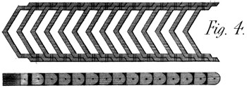
This Chain is shewn in fig. 4 of Plate 17. The links are formed to an angle, in the middle, similar to that of the wheels at their pitch line; of which the obliquity, for the V wheels, is greater than 15 degrees; since the thickness of the wheel, is necessarily divided between the right and left handed slope. Be this slope what it may, the chain and wheels must of course be alike, measured at the pitch line of the wheels; and then, as the chain geers with a straight line of pinions, they work together without sensible friction on the teeth, and with nearly the same steadiness of motions as wheels would work together. Moreover, if the drum be of a pretty large diameter, its action will likewise be nearly equable. The degree of precision depends, however, on the fineness of the pitch, and the largeness of diameter in the drum; since every chain bending round a cylinder must form a polygon of a greater or less number of sides, dependent on these circumstances. I repeat then, that while the chain works on the pinions in a tangent to them all, there is no necessary friction between them; nor yet on the pins of the chain, but only at the drums which actuate and return the latter:—I shall dismiss the subject, by observing, that I have used the term drum, because of the similarity of this chain-motion to that produced by bands, where drums are generally the movers. But here, this supposed drum is a wheel of proper diameter, cut into teeth similar to those of the pinions; and placed at the same height on its spindle. I have reason to think that this chain, carefully made, would be an useful addition to the bobbin and fly frame, applied both to the bobbins and spindles, instead of the bands now in use; which, though a convenient resource, give a result equally uncertain and imperfect.
OF A SERPENTINE BOAT OR VESSEL, To lessen the Expence of Traction, &c.
The present description of this Machine, will consist, chiefly, of a translation from my own specification, given at Paris with the application for a Brevet, or Patent, obtained in the year 1795, and which is thus introduced.
“It is a well-known fact, that the longer any Boat or Vessel is, in proportion to its width, the less power it requires to convey a given load, from one place to another. But these lengths cannot be extreme, without introducing a degree of weakness, that would offer great danger in the use of such vessels. If then a Boat of a given volume, be divided into several long and narrow ones, the head of each adapted with a certain exactness to the stern of its forerunner, they will (with the trifling difference arising from the asperities of their surfaces) all move through the water with the same ease as any single one; and carry, unitedly, the same weight as did the large Boat before it was divided. This idea constitutes the principle of my Serpentine Vessel.”
“This Invention is not to be considered as an imitation of the well-known manœuvre of towing one vessel in the wake of another: for the resistance of the vessels thus towed, remains nearly, though not quite the same as if drawn along separately. But here, by the adaptation of the prow of one Boat to the poop of another, the first alone suffers resistance from the water—which, although it enters between the joints, strikes only the first—and from this it follows, that the resistance of these vessels, in passing from one place to another, bears no necessary proportion to the weight they carry.”
“Thus then, I obviate the necessity of having broad vessels to carry the heaviest burdens; for I disseminate the load over an indefinite length: by which method also, my vessel rides in shallower water, and depends less for its passage, on the state of the rivers or the seasons. Besides, they require a much less number of horses, or exertion of power, to transport a given quantity of goods; admitting at the same time, a greater swiftness of motion. And finally, if these vessels travel through different towns on the same voyage, the goods of each town may be lodged in the same part, and merely detached in passing, so as to lose no time in unloading them.”
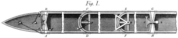
“Fig. 1 of Plate 18, shews the plan of several forms which I give to the articulations or separate parts of these vessels: so as to connect them strongly, yet leave them, as a whole, in some degree flexible. The form A B, is, for the first boat, a straight line across to form the stern, and for the second an obtuse angle terminated by a semi-sphere or vertical semi-cylinder, which enters a hollow and similar figure in the first Boat—which latter, in this case, forms the Head of the whole Serpentine Vessel.”
“These two parts or joints, of which we have been speaking, are held together by a rope c d e f, which, fastened to the second part at c, passes over two pulleys e d, in the head, to the small capstan f, by which, both parts are bound together as tightly as may be judged proper. If it were thought necessary, the spaces A B might be underlined with a piece of leather or metal, not to prevent the water from entering between the Boats, but to prevent its striking those which follow the others through the water—a precaution less urgent in the other kind of joint we are about to describe.”
“C D, in this same figure, presents another form of the head and stern of two contiguous Boats or parts; (which, to save room, are both supposed to be broken off at some point between their ends:) where as in the former case, the Boats are connected so as to remain horizontally flexible. These forms are semi-cylindrical, the stern concave, and the head convex, to the same radius; and the motion takes place around a bolt and pulley p, reeved with a rope coming from one side of the first Boat near C and led again to a small windlass or capstan placed on the other side near D. E F, is another modification of the same kind of joint: the centre of which is a bolt or stud q, (better seen at q in the 2d. figure) over which a triangular frame falls from the preceding Boat, and thus connects them instantaneously; leaving a certain flexibility in the horizontal direction.”

“Finally, G H shews a simple mean of connecting these Boats, on the supposition that both ends of each are formed alike to an obtuse angle in the middle of their breadth. It is a kind of hook r s, mounted in a frame turning on centres in the preceding Boat, and reaching over into the succeeding one; where it finds a hollow step of metal which receives and fits it, so as to hold these neighbouring Boats with sufficient tightness, but still with a certain degree of flexibility. Many other methods might be suggested, by which to form these joints; and almost any might be made to answer the purpose. I shall therefore leave this branch of the subject, observing only, that the second figure of Plate 18, is an elevation of the same things: which, generally, are marked with the same letters as far as they are visible.”

“The third figure presents the same objects in perspective; to which are now added two masts I K, placed obliquely on that Boat which forms the Head of the whole vessel. This obliquity is useful when the boat is drawn from one side only; but is injurious where the traction takes place indifferently on both sides: so that I should not, now, advise the use of this method—which indeed, I have avoided in fig. 4 of this Plate.”
“In every case, each of the masts carries a pulley near I K, over which passes a rope, the ends of which are fastened to the masts by proper brackets, near the deck: and to the middle of this rope is fastened the track rope L, by which the horses draw the Boat along. By these means the vessel is steered either to or from the land: for if the knot of the track rope is brought near the mast I, the Boat (which as before observed is the head of the whole vessel) veers towards the horses; and the contrary when the knot is drawn towards the mast K: both which effects are rendered the more prompt and decisive, by the use of the lee boards K M, the nature and use of which are already fully known.”
“But there are cases in which, from its great length, this Serpentine Boat would require a particular direction, for some intermediate point between its extremities; as although, in theory, every separate part ought to pass through the same water, yet in canals or rivers much bent, this may not invariably take place; and then a rudder would be useful, even in the middle of the vessel. I have therefore placed a pair at P R, fig. 3. Their motion is a vertical revolution, round a horizontal centre; and as they are formed obliquely to the sides of the Boat, when one of them is plunged into the water, it tends to drive the Boat in a sidewise direction: and if at any time it should be desired to stop the whole vessel, both rudders would be plunged at once into the water, when they would greatly contribute to that effect.”

“The fourth figure in this Plate 18, presents a general view of the vessel, comprising five articulations, (or Boats) besides the head and stern—which latter would fit each other without any intermediate parts, and form a Boat alone. Nor do these five parts by any means limit the useful number: but the Plate would not have contained more, unless on a scale too small to be distinctly understood.”
“Returning now to fig. 1, we observe the ropes A D F H and B C E G, which are supposed fixed to the stern Boat, and carried to the capstans represented in the Head. These ropes consolidate the whole fabric, and act, occasionally, as a kind of muscle, to govern the larger evolutions. These ropes pass in the brackets placed near the joints A B and C D, &c. being under the gang ways, of which a portion appears at S fig. 3, hung upon hinges, that they may be turned up when the Boat is used in narrow water.”
To the above specification were added the following remarks, which still apply to this kind of vessel, navigating on canals and inland rivers: “this vessel admits of the use of every kind of mover; such as men, horses, wind, or the steam engine; the latter of which I propose to apply to it in a manner equally simple and effectual; especially so as not to injure the banks of any canal, &c. by acting against and disturbing the water.”
I need not repeat that this Invention dates as high as 1795: as the Brevet was issued in that year. It may be added that four parts of such a Boat were executed about the same time; namely, the head, the stern, and two intermediate pieces: making together a length of 100 feet; and these, loaded to a certain depth with stones, were drawn up the river Seine by a single horse on a trot—which would likewise have taken place had the Boat been ten times as long; since, as before mentioned, the resistance of this kind of vessel bears no given proportion to the Load it carries.
OF A MACHINE For destroying, or lessening Friction.
I think it may be assumed that friction is fully expressed by the word rubbing: and that where rubbing cannot be found, friction does not exist; especially that kind of friction which opposes the motion of machinery—in which respect, the subject is chiefly thought interesting to mechanicians. It would be abandoning my intended plan in this work, to treat largely of friction, or any other accident in practical mechanics; but having already declared myself “no believer in several sorts of friction,” I am in a measure bound to introduce my description of the two following articles, by a short reference to the general subject. I offer then the following remarks, more as hints for the consideration of learned experimenters, than as conclusions sufficiently proved to become rules in practice. What I cannot help urging strongly is, that rolling is not rubbing. If it were, I would ask in what direction it takes place? Is it in that of the plane rolled over? or in that of the radii of the rolling body? If in the former, it would indeed glide over that plane, and occasion or suffer real friction; but this, I think, is not pretended. If this motion is in the latter direction, (that of the radii of the rolling body) it is indefinitely short, compared with the progressive motion of the rolling body, so that the power of the latter, to overcome any resistance in that direction, is infinite. Whenever therefore, in experiments of this kind, a finite resistance is perceived, it must, I should think, be ascribed to other causes, and not to friction. In my wheels for example, (see a former article) where there is a real and deep penetration of the surfaces, I have proved that the friction between the teeth is less than the distance between two of the last particles of matter: and surely, when penetratration is purposely made as small as possible (by the use of smooth rollers) the friction thence arising must be still more imperceptible. But I hear it answered, that this friction is both known and measured! and certain celebrated experiments are adduced to prove it. But what I most wonder at is, that a person so truly learned as the author of those experiments, should have adopted so remarkable a misnomer; in which to all appearance, indentation has usurped the name of friction. Nor let this surprise, surprise any body: nor especially, offend this learned author himself; for I am persuaded that the sole act of placing these wooden rollers, on these surfaces of wood, must indent them both sufficiently to account for all the facts observed; and still more so when loaded with weights of 100, 500, or 1000lbs. No friction, therefore, is requisite in accounting for the resistance of these rollers to horizontal motion. Nay, I submit, whether a resistance, arising from indentation alone, would not prove to be “directly as the pressures and inversely as the diameters of the rollers?” To me the subject presents itself under three aspects: either the whole indentation takes place on the rollers, when they are very soft and the rulers very hard; or the latter, when they are very soft and the rollers very hard: or, which is most likely, this indentation takes place on both bodies at once; so as to produce a surface of contact, intermediate between the straight surface of the rulers, and the cylindrical surface of the rollers. But in either case, the place of resistance to horizontal motion, must be out of the line of direction of the roller’s centre of gravity: and thus would the roller present more or less resistance, independently of every thing that can be called friction: and which degree of resistance will continue to exist as long as the place of contact is made to change on the rulers—for thus to change this place of contact is to renew this indentation; which process will elicit a resistance equal to what would be observed were the roller (without indentation) forced up a plane, inclined to the horizon in the same angle as a line, drawn from the centre of the roller to the extreme edge of the surface of contact, makes with the perpendicular.
I cannot possibly enter at length into this subject, as it makes no part of my engagement to the public: but I would observe that this resistance is, a fortiori, something besides friction, since greasing the surfaces “did not cause any sensible diminution of it;” whereas it made a difference of one half! in some others of the experiments alluded to.[4] Were I asked the reason, I should answer, because friction had little or nothing to do with it; and I would say further, that greasing or oiling these surfaces would most likely increase, instead of diminishing, their resistance to horizontal motion: namely by softening them, and making them more susceptible of change of figure: which opinion gathers strength from another fact adduced, viz: that “rollers of elm produced a friction (or resistance) of about 2⁄5 greater than those of lignum vitæ:” but why? because elm is relatively soft and lignum vitæ hard—the only cause that appears sufficient to account for the facts observed.
I must now leave these remarks to persons having more means and leisure than myself, to pursue the subject; wishing only, that useful truth may result from them: and that this unbelief of mine “in several special kinds of friction,” may at least be found to have some reasonable ground to rest upon.
But I may be opposed in some of my statements by the fact, that friction rollers, with centres, have been used with little advantage; and often laid aside. This I acknowledge; and go a step further. Friction is by no means of so much consequence as it was once thought to be: and is not the source of the greatest defalcations that occur in the use of power. Yet, to get rid of it, in some cases, would be of considerable importance; and the subject deserves at least the attention of every intelligent mechanician.
Those who have used friction rollers, know that it is a thing of great difficulty, to place their axes exactly parallel to that which they are intended to support: and even, if rightly placed at first, that a small degree of abrasion, greater on one pivot than another, will soon destroy that parallelism; and thus introduce a growing friction, capable, at length, of rendering the whole completely useless: for although the original friction is lessened by being transferred to a slower-moving axis, yet the latter still resists in some degree, say 1⁄4 of the whole; (its pivots being 1⁄4 of its whole diameter) so that the cohesion, or something else, between the main shaft and the friction roller, (thus resisted) must be sufficient to drag round the latter, against about 1⁄4 of the original friction; which in a word it cannot do without some relative motion between those surfaces, the friction roller lagging behind the main shaft, until its own friction is overcome by another. And thus it is, that a friction roller of this kind, does not make so many revolutions on its pivots, as its diameter compared with that of the main shaft, would imply; for example, if the shaft were 4 inches in diameter and the friction roller 8 inches, the latter would not complete one revolution against two of the former. There would thus remain a difference spent in real friction, in addition to that on the axis of the friction roller. Besides this, we have the want of parallelism above mentioned; which occasions a rubbing, in the direction of the shafts, small indeed in quantity, but for that reason very powerful in bringing on a change of form, and thereby hastening the common destruction. Both these accidents, therefore, make friction rollers, in general, an unsatisfactory and perishable expedient: and it is to make them less so, if not entirely to cure these evils, that the two following articles are designed.
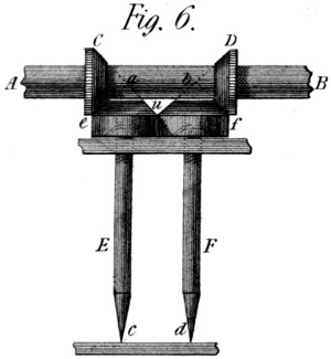
In fig. 6 of Plate 17, A B is an axis which it is desirable to divest of its friction. To do this, as nearly as may be, I connect with it two rings of hard metal C D, formed as truncated cones; and under the shaft, in the same vertical plane, I place two smaller shafts E F, carrying on their tops, other two cones, similar to the former. The summits of each pair of cones meet of course in the points a b of the main shaft; and, on the principle of bevel geer, every contiguous part of the touching cones moves with the same velocity: so that there is no sensible rubbing between them—for, 1st. the pivots c d, are hard and pointed, and run on the hardest steps that can be obtained; and, 2ndly. the tendency of the cones u toward each other, is repelled without friction by the cylinders e f, attached to them, and which lean right and left against each other, turning with the same velocity, without causing any friction, or any creeping, between the two pairs of cones e C, and f D. All the weight therefore, of the shaft A B, (which of course is kept in place in the other direction by proper side cheeks, &c.) rests on the points of the vertical shafts E F, accompanied by no sensible tendency of these points to quit the places assigned to them.
OF A SECOND MACHINE, To avoid or diminish Friction.
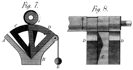
In Plate 17, figs. 7 and 8, offer a mechanism different from the preceding, though intended to produce a similar effect. Referring to that cause of friction which consists in the want of parallelism between a principal shaft and its friction rollers, I here introduce a form for the latter, which admits of this consideration being in a measure neglected. These friction rollers are only portions of cylinders; and they have no shafts. They turn simply on a sharp edge, placed in a prismatic box A B, in a well formed angle of which, they move to and fro, without rubbing. When at rest, these axes D C D, (fig. 7 and 8) are drawn against the right hand side of the box, by small weights E; and the shaft is carried by one or the other of them, according as they are, or are not, within reach of its radius. Thus, in the present position of the shaft, (see fig. 7) the second arc C supports it, the third having fallen behind the first, so as not to be seen: and the first arc D being on the point of taking up the load. In short there are six spaces, either left or cut on the shaft, opposite the three arcs D C D. 1st. one space, of 1⁄3 of the circumference, left concentric with the real centre of the shaft, opposite the first arc D, followed by 2⁄3 of a circumference cut an eighth of an inch lower. 2ndly. another third of a circumference opposite the second arc C, beginning where the first ends, and followed by 2⁄3 of a circumference cut an eighth of an inch lower: and 3rdly, another space of 1⁄3 in circumference, opposite the arc D, followed by a similar space of 2⁄3 cut an eighth of an inch lower. By these means the shaft is never without a concentric bearing: and the better to secure this property these arcs left, may be each of them more than one third of a circumference in length, so as to avoid the least drop at each change of roller; and even to give the shaft a support from two rollers at once, during a good part of its revolution.