Chapter VI · WELL BORING AT GREAT DEPTHS. (continued 2)
Reading edition
The boring operations are carried on uninterruptedly during the process of tubing, excepting only for a few minutes when fresh tubes are being added. It will be seen that the cast-iron well is in this case the ultimate abutment against which the pressure is exerted in forcing the tubes down, instead of the weight of the boring machine with stones and pig iron added, as in the case where the screw-jacks are used; the hydraulic method was designed specially for the work at Gosport, and has acted most perfectly. Both the cast-iron well and the bore-hole are entirely shut off from all percolation of sea-water, by first filling up the well 30 feet with clay round the tubes, and making the tubes themselves water-tight at the joints at the time of putting them together.
In the event of any accident occurring to the tubes while they are being forced down the bore-hole, such as requires them to be drawn up again out of the hole, the prong grapnel, Fig. 204, is employed for the purpose, having three expanding hooked prongs, which slide down readily inside the tube, and spring open on reaching the bottom; the hooks then project underneath the edge of the tube, which is thus raised on hauling up the grapnel. In case the tubes get disjointed and become crooked during the process of tubing, the long straightening plug, Fig. 205, consisting of a stout piece of timber faced with wrought-iron strips, is lowered down inside them; above this is a heavy cast-iron block, the weight of which forces the plug past the part where the tubes have got displaced, and thereby straightens them again.
Although there are few localities where the geological formation is not favourable to the yield of pure water if a boring be carried deep enough, yet it rarely happens that free-flowing wells such as those in Paris and Hull are the result. Generally after the water-bearing strata have been pierced, the level to which the water will rise is at some depth below the surface of the ground; and only by the aid of pumps can the desired supply be brought to the surface. Various pumping arrangements have therefore been adopted to suit the different conditions that are met with.
It is not the object of the present work to treat of the forms and fittings of pumps, and the following details are only given as completing Mather and Platt’s system.
It is always desirable to sink a cast-iron well, such as that at the Horse Fort, as nearly as possible down to the level at which the water stands in the bore-hole. The sinking of such a well is rendered an easy and rapid operation, with the aid of the boring machine in winding out the material from the bottom, and keeping the sinkers dry by the use of the dip-bucket, shown in Figs. 214 to 216, which will lift from 50 to 100 gallons of water a minute, for taking off the surface drainage. A well having thus been made down to the level of the water in the bore-hole, the permanent pumps are then applied to the bore-hole as follows, the size of the pumps varying according to the diameter of the bore-hole. Taking the case of a 15-inch bore-hole, a pump barrel consisting of a plain cast-iron cylinder, say 12 inches diameter and 12 feet long, as shown in section in Fig. 219, is attached at the bottom of cast-iron or copper pipes, which are 1⁄4 inch larger in diameter than the pump barrel, and are coupled together in lengths by flanges, Fig. 217. By adding the requisite number of lengths of pipe at the top, the pump barrel is lowered to any desired depth down the bore-hole: the nearer to the depth of the water-bearing strata the better. The topmost length of pipe has a broad flange at its upper end, which rests upon a preparation made to receive it on the cast-iron bottom of the well, as at C in Fig. 219.
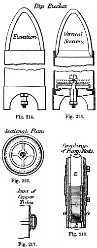
Figs. 214-218.
A pump bucket D, Fig. 219, with a water passage through it and a clack on the top side, is then lowered into the barrel, being suspended by a solid wrought-iron pump-rod E, which is made up of lengths of 30 feet coupled together by right-and-left-hand screw-couplings, as in Fig. 218. A second bucket F of similar form is also lowered into the pump barrel, above the first bucket, and is suspended by hollow rods G coupled together in the manner just described; the inside diameter of the hollow rods G being such that the couplings of the solid rods E may pass freely through. The pump-rods are carried up the well A to the surface, where the hollow rod of the top bucket is attached to the horizontal arm of a bell-crank lever H, Fig. 219; and the solid rod of the bottom bucket, passing up through the hollow rod of the top bucket, is suspended from the horizontal arm of a second reversed bell-crank lever K, facing the first lever H. As the extremities of the horizontal arms of the levers meet over the centre of the well, one of them is made with a forked end to admit of the other passing it. The vertical arms of the two levers are coupled by a connecting rod L, and a reciprocating motion is given to them by means of an oscillating steam cylinder M, the piston-rod of which is attached direct to the extremity of one of the vertical arms; a crank and flywheel N are also connected to the levers, for controlling the motion at the ends of the stroke. With the proportion shown in the Figure of 3 to 4 between the horizontal and vertical arms of the bell-crank levers, the stroke of 5 feet 4 inches of the steam piston gives 4 feet stroke of the pump. The reciprocating motion of the reversed bell-crank levers causes the two buckets to move always in opposite directions, so that they meet and separate at each stroke of the engine. A continuous flow of water is the result, for when the top bucket is descending, the bottom bucket is rising and delivering its water through the top bucket; and when the top bucket rises, it lifts the water above it while the bottom bucket is descending, and water rises through the descending bottom bucket to fill the space left between the two buckets. In this way the effect of a double-acting pump is produced.
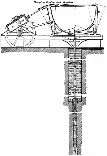
Fig. 219.
Although a continuous delivery of water is thus obtained of equal amount in each stroke, it is found in practice that a heavy shock is occasioned at each end of the stroke, in consequence of both the buckets starting and stopping simultaneously, causing the whole column of water to be stopped and put into motion again at each stroke. As an air-vessel for keeping up the motion of the water is inapplicable in such a situation, a modified arrangement of the two bell-crank levers has been adopted, which answers the purpose, causing each bucket at the commencement of its up stroke to take the lift off the other, before the up stroke of the latter is completed. By this means all shock is avoided, as the first bucket gently and gradually relieves the second, before the return stroke of the second commences.
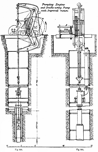
Figs. 220, 221.
Larger image (254 kB)
In this improved pumping motion, which is shown in Figs. 220, 221, the two bell-crank levers H and K, working the pump buckets, are centred one above the other, the upper one being inverted; the vertical arms are slotted, and are both actuated by the same crank-pin working in the slots, the revolution of the crank thus giving an oscillating movement to the two levers through the extent of the arcs shown by the dotted lines in Fig. 220. The solid pump-rod E suspending the bottom bucket D is attached to the upper bell-crank lever K, and the hollow rod G of the top bucket is suspended from the lower lever H; the crank-shaft J working the levers is made to revolve in the direction shown by the arrow in Fig. 220, by means of gearing driven by the horizontal steam-engine P.
The result of this arrangement is, that in the revolution of the crank the dead point of one of the levers is passed before that of the other is reached; so that the bucket which first comes to rest at the end of its stroke is started into motion again before the second bucket comes to rest. Thus in the lifting stroke of the bottom bucket worked by the upper lever K, the bucket in ascending has only reached the position shown at D in Fig. 220, at the moment when the top bucket worked by the lower lever H arrives at the bottom extremity of its stroke, and the bottom bucket D, which is still rising, continues to lift until it reaches its highest position, by which time the top bucket has got well into motion in its up stroke, and is in its turn lifting the water.