Appendix
Reading edition
Characteristics of the Wright Flight Engines
1903 First flight engine[a] 1904-1905 Experimental flights 1908-1911 Demonstrations and service 1911-1915 service
Cyl./Form 4/flat 4/flat 4/vertical 6/vertical
Bore and stroke (in.) 4×4 4-1/8×4 4-3/8×4 4-3/8×4-1/2
Displacement (cu. in.) 201 214 240 406
Horsepower 8.25-16 15-21 28-42 50-75
RPM 670-1200 1070-1360 1325-1500 1400-1560
MEP 49-53 52-57 70-87 70-94
Weight (lb) 140-180 160-170 160-180 265-300
It is not possible to state the exact quantities of each engine that the Wrights produced up to the time that their factory ceased operation in 1915. Chenoweth gives an estimate, based on the recollection of their test foreman, of 100 vertical 4s and 50 6s. My estimate (see page 2) places the total of all engines at close to 200. Original Wright-built engines of all four of these basic designs are in existence, although they are rather widely scattered. The Smithsonian's National Air and Space Museum has examples of them all, including, of course, the unique first-flight engine. Their condition varies, but many are operable, or could easily be made so. Among the best are the first-flight engine and the last vertical 6, at the Smithsonian, the first vertical 6, at the United States Air Force Museum, and the vertical 4, at the Carillon Park Museum.
The Wrights were constantly experimenting and altering, and this in connection with the lack of complete records makes it almost impossible to state with any certainty specific performances of individual engines at given times. Weights sometimes included accessories and at others did not. Often they were of the complete powerplant unit, including radiator and water and fuel, with no clarification. In the table, performance is given in ranges which are thought to be the most representative of those actually utilized. Occasionally performances were attained even beyond the ranges given. For example, the 4×4-in. flat development engine eventually demonstrated 25 hp at an MEP of approximately 65 psi.
One important figure—the horsepower actually utilized during the first flight—is quite accurately known. In 1904 the 1904-1905 flight engine, after having been calibrated by their prony-brake test-fan method, was used to turn the 1903 flight propellers, and Orville Wright calculated this power to be 12.05 bhp by comparing the calibrated engine results with those obtained with the flight engine at Kitty Hawk when tested under similar conditions. However, since the tests were conducted in still air with the engine stationary, this did not exactly represent the flight condition. No doubt the rotational speed of the engine and propellers increased somewhat with the forward velocity of the airplane so that unless the power-rpm curve of the engine was flat, the actual horsepower utilized was probably a small amount greater than Orville's figures. The lowest power figure shown for this engine is that of its first operation.
No fuel consumption figures are given, primarily because no comprehensive data have been found. This is most probably because in the early flight years, when the Wrights were so meticulously measuring and recording technical information on the important factors affecting their work, the flights were of such short duration that fuel economy was of very minor importance. After success had been achieved, they ceased to keep detailed records on very much except their first interest—the flying machine itself—and when the time of longer flights arrived, the fuel consumption that resulted from their best engine design efforts was simply accepted. The range obtained became mostly a matter of aerodynamic design and weight carried. Orville Wright quotes an early figure of brake thermal efficiency for the 1903 engine that gives a specific fuel consumption of .580 lb of fuel per bhp/hr based on an estimate of the heating value of the fuel they had. This seems low, considering the compression ratio and probable leakage past their rather weak piston rings, but it is possible. In an undated entry, presumably in 1905, Orville Wright's notebook covered fuel consumption in terms of miles of flight; one of the stated assumptions in the entry is, "One horsepower consumes .60 pounds per horsepower hour"—still quite good for the existing conditions. Published figures for the 6-60 engine centered around .67 lb/hp hr for combined fuel and oil consumption.
The Wright Shop Engine
The engine was a single cylinder, 4-stroke-cycle "hot-tube" ignition type. The cylinder, of cast iron quite finely and completely finned for its day, was air-cooled, or rather, air-radiated, as there was no forced circulation of air over it, the atmosphere surrounding the engine simply soaking up the dissipated heat. Although this was possibly a desirable adjunct in winter, inside the small shop in Dayton, the temperature there in summer must have been quite high at times. The operating fuel was city illuminating gas, which was also utilized to heat, by means of a burner, the ignition tube. This part was of copper, with one completely closed end positioned directly in the burner flame; the other end was open and connected the interior of the tube to the combustion chamber. The inlet valve was of the usual automatic type while the exhaust valve was mechanically operated. The fuel gas flow was controlled by a separate valve mechanically connected to the inlet valve so that the opening of the inlet valve also opened the gas valve, and gas and air were carried into the cylinder together.
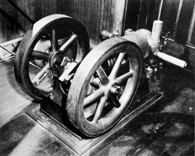
Figure 16.—Shop engine, 1901, showing governor and exhaust valve cam. (Photo courtesy R. V. Kerley.)
The engine was of normal stationary powerplant design, having a heavy base and two heavy flywheels, one on each side of the crank. These were necessary to ensure reasonably uniform rotational speed, as, in addition to having only one cylinder, the governing was of the hit-and-miss type. It had a 6×7-in. bore and stroke and would develop slightly over 3 hp at what was apparently its normal operating speed of 447 rpm, which gives an MEP of 27 psi.
The engine is noteworthy not only for its very successful operation but also because it incorporated two quite ingenious features. One was the speed-governing mechanism. As in the usual hit-and-miss operation, the engine speed was maintained at a constant value, the output then being determined by the number of power strokes necessary to accomplish this. The governor proper was a cylindrical weight free to slide along its axis on a shaft fastened longitudinally to a spoke of one of the flywheels. A spring forced it toward the center of the wheel, while centrifugal force pulled it toward the rim against the spring pressure. After each opening of the valve the exhaust-valve actuating lever was automatically locked in the valve-open position by a spring-loaded pawl, or catch. The lever had attached to it a small side extension, or bar, which, when properly forced, would release the catch and free the actuating lever. This bar was so positioned as to be contacted by the governor weight when the engine speed was of the desired value or lower, thus maintaining regular valve operation; but an excessive speed would move the governor weight toward the rim and the exhaust valve would then be held in the open position during the inlet stroke, so no cylinder charge would be ingested. Since the ignition was not mechanically timed, the firing of the charge was dependent only on the compression of the inlet charge in the cylinder, so it made no difference whether the governor caused the engine to cease firing for an odd or even number of revolutions, even though the engine was operating on a 4-stroke cycle at all times.
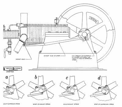
Figure 17.—Shop engine, 1901, showing operation of exhaust valve cam. (Pratt & Whitney drawing.)