Chapter VIII · NOTE ON LINK MOTIONS.
Reading edition
The Link Motion.—In engines whose duty frequently varies, as in the familiar case of a locomotive, permanent alteration of lap would not meet the requirements of the case, for the amount of expansion should be susceptible of ready variation at any time, in accordance with alterations in the weight of train, gradients, and weather. The link motion, in addition to being a reversing gear, is also a “variable expansion” gear. A precise analysis of any given case of link motion is a somewhat difficult operation, but, speaking broadly, the link motion may be said to provide what is virtually an eccentric of different throw and advance for each degree of expansion. Although, actually, the same two eccentrics remain constantly in use, the link motion may be so adjusted as to have an effect on the valve similar to that which would ensue 67upon the substitution, one for another, of different eccentrics as stated. Assuming that the lowest range of expansion is being used, the valve will have the travel, cut-off, and lead due for the most part to the throw of the actual eccentric and to its position with relation to the crank, almost as in the case of an eccentric whose rod is directly connected to the valve-spindle; now, as the link is raised (an operation sometimes termed “linking-up”) its centre gets nearer to the block on the end of the valve-spindle than it was before (i.e., nearer to “mid-gear”), and we get in effect:—
With link motion having “open” rods. A series of eccentrics of decreasing throw, but of increasing angular and linear advance.
With link motion having “crossed” rods. A series of eccentrics of decreasing throw and of increasing angular, but decreasing linear advance; throw, therefore, decreasing more rapidly than in the case of the link motion with “open” rods.
Take the case of a partially linked-up motion 68with open rods; we shall find that because the throw of the eccentric is lessened, the travel of the valve to the right and left of its central position will be diminished, and the 69ports will not be opened so wide to steam or exhaust; because of the increased advance of the eccentric, steam will be cut off earlier, compression and lead will also be earlier, expansion and compression lasting longer, and exhaust and admission being shortened. The difference between working in full gear and linked up is shown by the diagram in fig. 34.
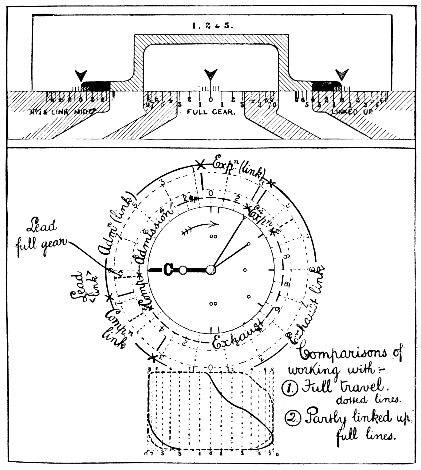
Fig. 34.
Below are diagrams showing the effect of putting the link motion in “mid-gear” (fig. 35) 71and of putting the link motion into “back gear” (fig. 36) while the engine is running ahead, as for a locomotive, but it will be understood that the effect of the compression shown in the latter will be modified by the 72lifting of the valve from its face, with the result that some compressed air and steam will go up the exhaust.
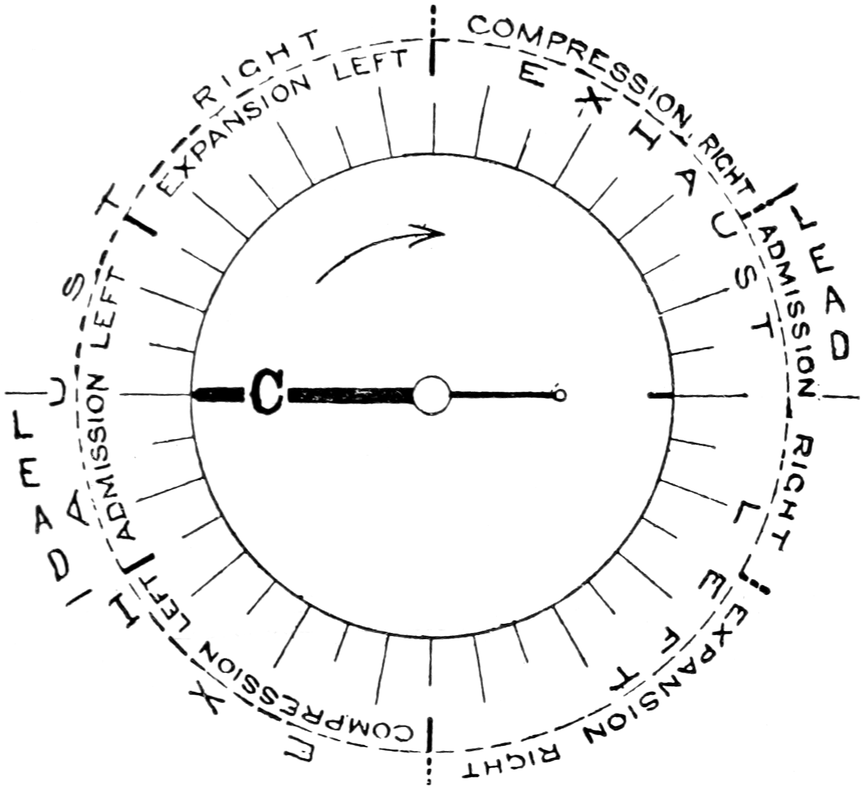
Fig. 35.
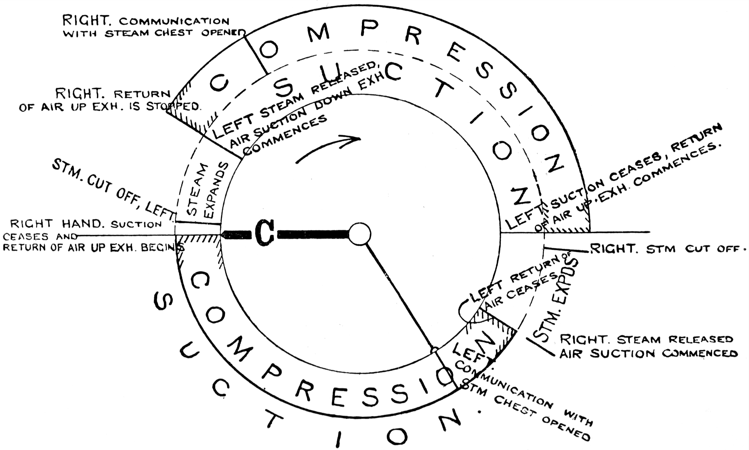
Fig. 36.
The set of diagrams forming fig. 37 is intended to give a comparative view of the effect upon the distribution of steam, of differently arranged valves and eccentrics. The operations taking place upon only one side of the piston are shown, except in that section of the diagram which concerns a shifted valve, in order to avoid confusion. The upper line of each diagram, being read from left to right, shows the operations which take place on the forward stroke, those of the return stroke being read from right to left upon the lower portion of each diagram.
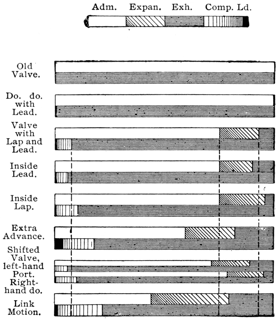
Fig. 37.
73