Chapter IV · DEAD CENTRE. ORDER OF CRANKS. CUSHIONING AND LEAD.
Reading edition
It is desirable at this point to clear the ground by touching for a moment upon one or two elementary matters which, if not now explained, might cause confusion subsequently.
Dead Centres.—A crank is said to be “on the centre” or “on the dead centre” when the connecting-rod and crank are in line, and this occurs twice in every revolution, as shown in fig. 11.
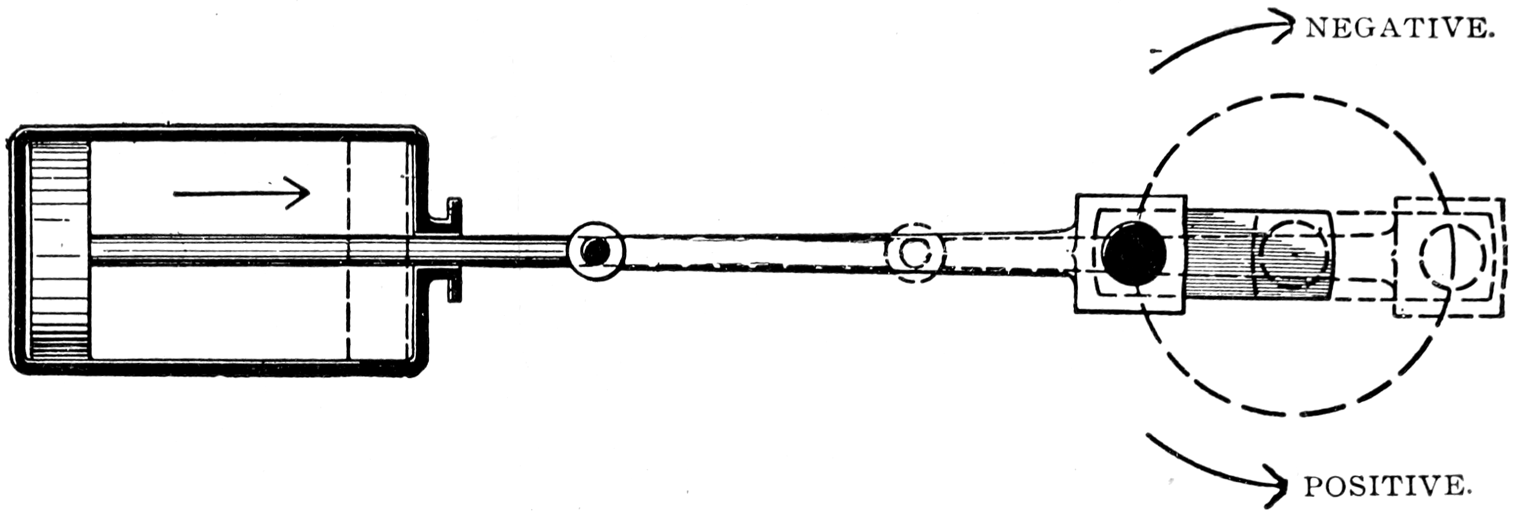
Fig. 11.—Dead Centre—Connecting Rod and Crank in Line.
Right-hand Crank to Lead.—The phrases “right-hand crank to lead,” or “left-hand crank to lead,” are sometimes used, and are confusing to beginners; the “leading” crank is that one which leads when the engine is running ahead. In most two-crank engines one of the cranks will be a quarter of a revolution (or less than half a revolution, where the cranks are not set at 90 degs.) in advance of its neighbour, and will, therefore, lead it in the direction in which it should go. Of course, 26that neighbour might be said to lead the other by being three-quarters of a revolution in advance (or more than half a revolution, where the cranks are not set at 90 degs.), and this is where a little confusion sometimes arises; the leading crank must always be taken as that one which is less than half a revolution in advance of its fellow when the engine is running ahead, and in locomotives and similar engines is “left-hand” or “right-hand,” according as it lies to the left or right of a spectator looking from behind the crank-shaft towards the cylinders. (See fig. 12, which shows two arrangements of the driving cranks of an English locomotive. The cylinders are supposed to be to the right of the wheels.)
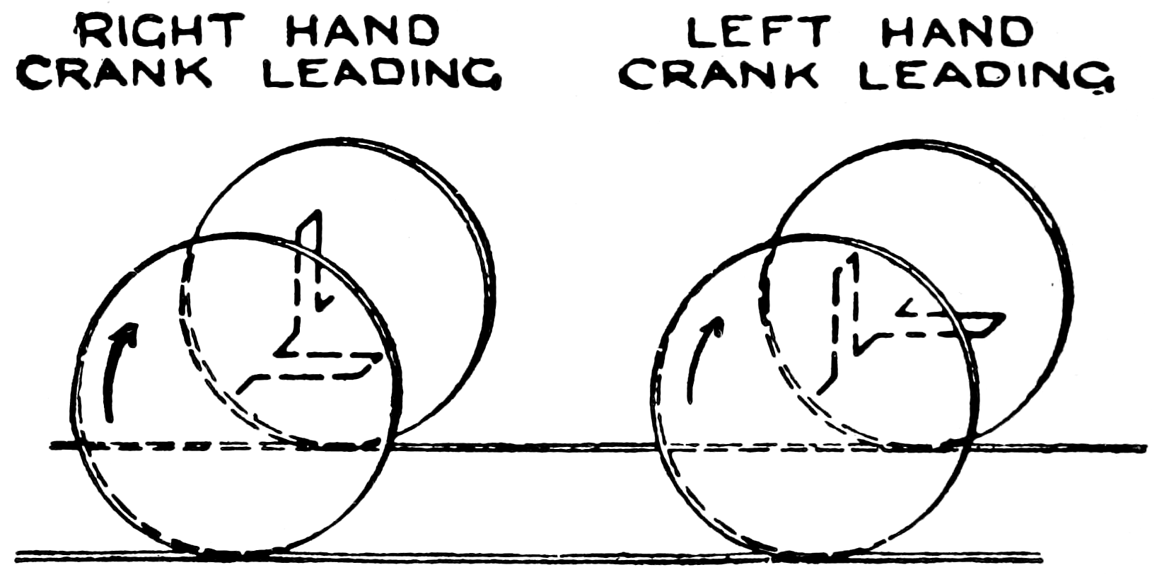
Fig. 12.—Order of Cranks.
27The accompanying diagram (fig. 13) will perhaps serve to make clear without further explanation the meaning of the expression, used with reference to three-crank marine engines, of “order of cranks, high, intermediate, low,” or “order of cranks, high, low, intermediate,” as the case may be.
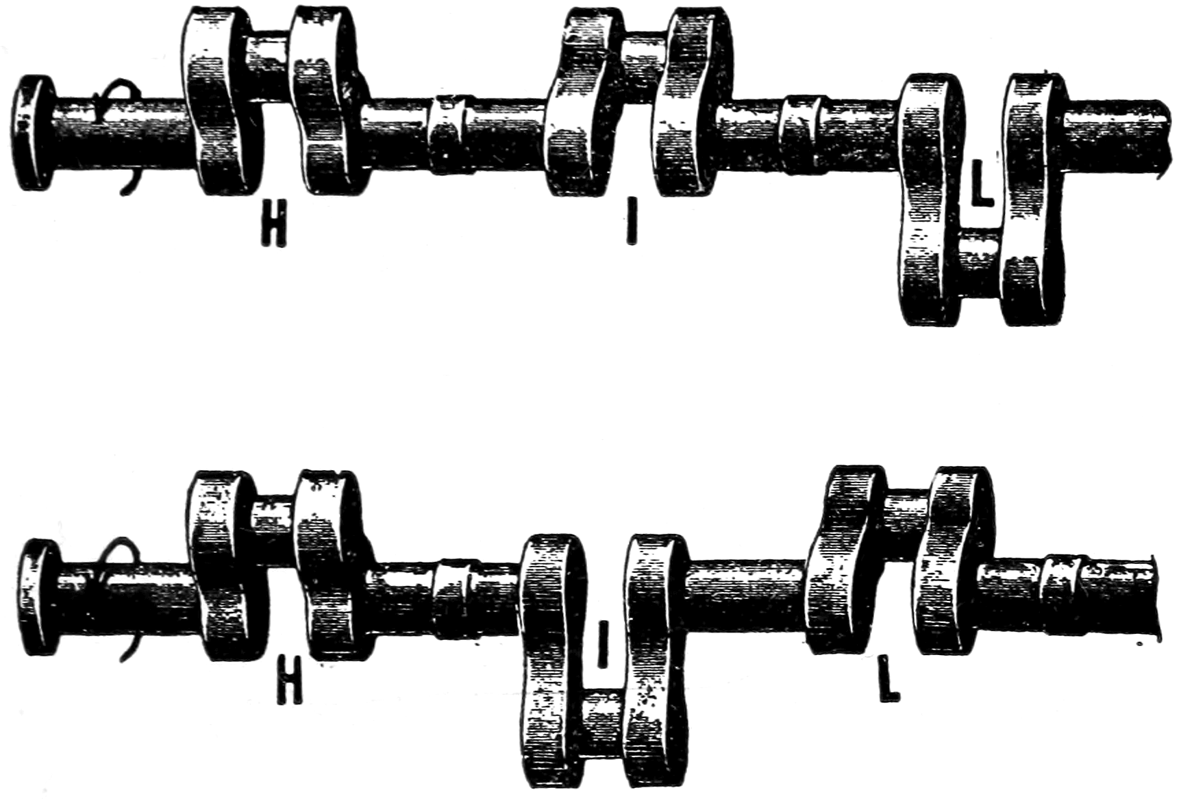
Fig. 13.—Order of Cranks.
Let us revert here to one of the points previously noted, which was that the simple valve, when we had it in connection with an eccentric set 90 degs. in advance of the crank, would not admit steam to the cylinder at the exact commencement of the stroke, i.e., when the crank is on either of the “dead centres.”
28Keeping this fact in mind, we will consider the matters of
Cushioning and Lead.—It has long been found desirable (especially in quick-running engines) that the motion of the returning piston should be opposed as it arrives at either end of its stroke, so that the moving weights of piston, piston-rod, and connecting-rod may be “cushioned,” to prevent injurious stresses and to conduce to easy running. To use a homely illustration, one might say that just in the same way is it desirable, when striking out from the shoulder, to have one’s adversary within range, that he may provide the necessary “cushioning,” and so prevent stresses in one’s arm and possible dislocations.
This “cushioning” is provided in part by checking the exit of the exhaust steam, as will be shown later, and in part by setting the eccentric a little more than 90 degs. (fig. 14) in advance of the crank, so that the valve commences to open the port to admit steam in front of the returning piston before it arrives at the end of its stroke, continuing to open the port as the piston comes to a rest, and is started on the return stroke.
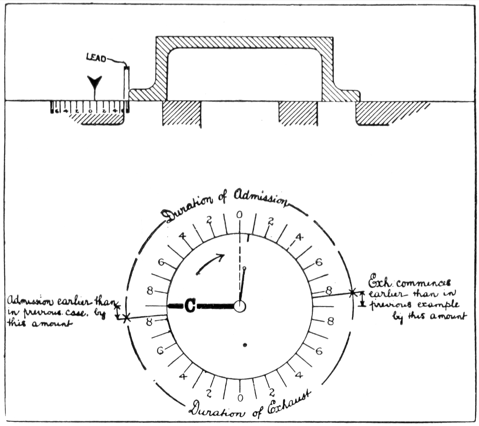
Fig. 14.
The amount to which the port is found to be open when the piston is at the end of its stroke 29is called the “lead” of the valve, and it would be expressed as “one-eighth of an inch lead,” or “three-sixteenths of an inch lead.” etc., as the case might be. To set this valve for lead, keep the piston at the end of its stroke, and set the eccentric back until the valve is opened to the desired lead; then the eccentric 30would be fixed in its newly-found position, as shown in fig. 14. The radius of the “eccentric-arm,” which is the lighter of the two radial lines on the disc in fig. 14, is equal in length to one-half of the travel of the valve, and therefore does not reach the edge of the disc, at which, however, there is a short guiding-mark in the line of the eccentric-arm “produced.” By using this guiding-mark and moving the arrow-head of the valve over the scale on the ports, in correspondence with the movement of the guiding-mark on the edge of the disc within the circular scale, the valve, the main crank (C), and the eccentric can be operated in concord, very much as if they were mechanically connected.
The explanation just given of the meaning of lead, and of its effect, should be borne in mind, as we shall presently have to consider it in conjunction with other matters, for, as has been said, there is something more than “lead” employed in the production of cushioning.
31