THE ROYAL MINT.
Reading edition
Coining is the term applied to the processes employed in the manufacture of money. It is proposed to describe the present mode of manufacture; but it may be as well to state, that in remote periods money was made by cutting out a piece of metal somewhat of the form of the intended coin, and imparting the device to it by the blow of a sledge-hammer. For this purpose the blank piece of metal was laid upon a die, say the obverse, fixed into a block of wood or stone, supposed to have been so large as to absorb the vibration caused by the blow, and to a great extent prevent the quivering which would naturally arise, and cause unsteadiness. The workman then took the other die, say the reverse, and passing it through a folded sheet of lead, in order to avoid the shock to the hand, he placed the engraved part on the blank, which was resting on the lower die, and held it firmly while another workman struck it with a sledge-hammer. It is worthy of remark that a piece of lead such as that described is in the Museum of Dies at the Royal Mint; and although its surface, by the action of the atmosphere and other causes, is now converted into carbonate of lead, indentations caused by the tips of the workman’s fingers are evident. This piece is believed to have been used with a die of Edward IV. At a later period the upper die was held in a twisted hazel stick. After each blow the dies were what is technically termed locked together; that is, the lower and upper dies were made to fit into the partly-formed coin, so that neither die could turn without turning the whole mass, and then a second or third blow was given, till the coin was completed. An improvement on this method was effected by fitting the two dies into rods of iron, which may be represented as a pair of tongs; the flat parts which are used to take a coal would then be the position occupied by the dies. This plan saved the operator some risk of bruised fingers, but the process was essentially the same as the original one; and to money produced by either means was applied the term hammered money, in contradistinction to milled money; that is, money which was made from blanks obtained from fillets which had been rolled in a very rough kind of rolling mill, driven by horse power—the germ from which sprang the present machinery. On this point it is perhaps of interest to quote a passage from the Report made to the Lords of the Treasury in 1695 by Mr. William Lowndes, who says:—“All the moneys we have now in England, both gold and silver, are reducible to two sorts, one stamped with the hammer, and the other pressed with an engine called the mill. The gold or silver of the hammered money is first cast from the melting-pot into long bars, those bars are cut with shears into several square pieces of exact weight for sovereigns, angels, crowns, half-crowns, shillings, &c. Then with tongs and hammer they are forged into a round shape, after which they are blanched (that is, made white or refulgent by nealing or boiling), and afterwards stampt or impressed with an hammer to make them perfect money. This method of making money with the hammer (as appears in the said red book) was practised in the reign of King Edward the first” [the book referred to is in the Exchequer] “and this kind of hammered money continued through all the reigns of succeeding Kings and Queens till about the year of our Lord 1663, when by several warrants and command of the King, Charles the Second: to wit, by one warrant, dated the fifth of November, 1662; one warrant, dated the eighth of April, 1663; and a third warrant, dated the twenty-fourth of December, 1663; the other sort, called milled money, was first fabricated to be current in England in this manner: first, the gold or silver is cast out of the melting-pot into long flat bars, which bars are drawn through a mill (wrought by a horse), to produce the just thickness of guineas, half-guineas, crowns, half-crowns, shillings, &c. Then with forcible engines called cutters, which answer exactly to the respective sizes or dimensions of the money to be made, the round pieces are cut out from the flat bar, shaped as aforesaid (the residue whereof, called sizel, is melted again), and then every piece is weighed and made to agree exactly with the intended weight, and afterwards carried to other engines (wrought secretly), which put the letters upon the edges of the larger silver pieces, and mark the edges of the rest with a graining. The next thing is the blanching, performed as above; and at last every piece is brought to the press, which is called the mill (wrought of the strength of men), and there receives the impression, which makes it perfect milled money.”
The processes now used are as elaborate as the old methods were simple; but considering the requirements of the present day, and the enormous quantity of money produced, it must not be expected that our coins will, for depth of engraving, bear comparison with those of the Romans, who, though succeeding in producing finished works of art, seem to have forgotten the wear and tear to which they would be subjected, and so left them, as a rule, free from a protecting edge; hence they would lose their image and superscription at a far earlier date from their birth or manufacture than would well-made coins of the present period.
It was formerly believed that gold could be sent to the Mint to be coined free of charge to the importer; such, however, was not the case. By the Act 33 Victoria, cap. 10, several Acts relating to the coinage are repealed, and all persons[7] obtain the right to send gold to the Mint to be coined on the following terms:—
“8. Where any person brings to the Mint any gold bullion, such bullion shall be assayed and coined, and delivered out to such person, without any charges for such assay or coining, or for waste in coinage. Provided that (1)—If the fineness of the whole of the bullion so brought to the Mint is such that it cannot be brought to the standard fineness under this Act of the coin to be coined thereout without refining some portion of it, the Master of the Mint may refuse to receive, assay, or coin such bullion. (2) Where the bullion so brought to the Mint is finer than the standard fineness under this Act of the coin to be coined thereout, there shall be delivered to the person bringing the same such additional amount of coin as is proportionate to such superior fineness. No undue preference shall be shown to any person under this section, and every person shall have priority according to the time at which he brought such bullion to the Mint.”
The standard for gold is fixed by the new Act at “Twenty-two carats fine and two carats of alloy in the pound weight troy”—the same that was specified in the 3rd Edward VI., 35th Elizabeth, 2nd Charles I., and 18th Charles II. Silver is maintained at the former standard of “Eleven ounces two pennyweights fine silver and eighteen pennyweights of alloy in every pound weight troy.” Until the passing of this Act silver was coined under that of George III., which repealed the Act 18 Charles II., as regards the coining of silver free of charge. The Act 33 Victoria, cap. 10, repeals that of George III., but fails to make provision for the coining of silver, which is therefore now coined under the Common Law; yet the new Act specifies the weight and fineness of the silver coinage. The omission was made because the Chancellor of the Exchequer thought it “unfair to introduce silver to this Act as it is a source of revenue;” a little later I will examine this statement.[8]
The Bank of England is practically the only “importer” of bullion to the Mint, and by coinage makes a considerable profit merely from its exceptional circumstances. By its charter and by Act of Parliament it is compelled to keep a stock of bullion equivalent to the excess of its authorised issue of notes—such authorised issue being secured by “Government debt” and “other securities”—which at the present time is fifteen millions; and gold, when at the Mint for coining, is esteemed as being still at the Bank. By the Act 7 and 8 Victoria, cap. 32, section 4, the Bank of England is compelled to purchase bullion, previously melted and assayed at the cost of the seller, at the rate of £3 17s. 9d. per ounce of standard gold, paying for it in Bank of England notes. Assuming that all the gold thus purchased is coined, the Bank makes a profit[9] of about £2,000 on each million. When its authorities desire to coin gold they give notice at the Mint, and subsequently send at stated intervals “importations” of say 200 ingots of gold, each weighing about 180 ounces, and previously assayed. Upon the arrival of these ingots at the Mint, they are taken to an office, where, in the presence of an officer from the Bank of England, a small piece is cut from each ingot, and hammered out into a kind of strip. This piece is then put into a paper marked with a letter which corresponds with the mark or letter on the individual ingot from which it was taken. This having been effected for each ingot, the pieces are forwarded with their respective ingots to the Mint Office, where their weight is determined and compared with that charged by the Bank of England. The pieces which have been hammered out and placed in a marked packet are called the “assay pieces.” The assay pieces are sent to the resident assayer in the Mint, who estimates and reports to the Master the amount of pure gold in each ingot. The report of the resident assayer is then submitted to the Bank authorities, and if they find it to agree with their own assayer’s report, the ingots are retained for operations in the Mint. When it is desired to get the ingots of gold into a form fit for coining, they have to be alloyed with copper, or fine gold must be added, so as to bring them to standard or crown gold, which consists of 22 parts of pure gold and 2 parts of alloy, or 91·66 per cent. of gold and 8·33 per cent. of copper in 100 parts. Copper is usually employed because it is cheaper, and forms a harder alloy than silver.
Supposing there are 100 ingots, having a total weight of 18,000 oz., and by assay it has been found that they contain 17,900 oz. of pure gold, it is required to bring them to the standard fixed by law. A rule-of-three sum tells how much alloy or how much gold is to be added. So, if 22 parts of pure gold require 2 parts of alloy, how much alloy will 17,900 parts require? The fourth term of the following proportion, viz., as 22:2::17,900:1,627·027, will show how much is to be added; but since there are already 100 oz. of alloy present, as indicated by the fact that 18,000 oz. contain within themselves only 17,900 oz. of pure gold, it is only necessary to add the excess required, viz., 1,527·027, so that these 100 ingots will produce 19,527·027 oz. of standard gold. Had the ingots been found to contain more alloy than is required, it would have been necessary to add so much pure gold as would have rendered the whole standard. The proportions of the metals having been determined, the whole mass is divided so as to make about 1,200 oz. of gold and alloy for each melting-pot. In practice it is customary to take the estimated amount of gold in a given number of ingots, and add so much alloy, or so much pure gold, as shall bring those ingots to standard, the whole weight being generally about 1,200 oz.; this is called potting the ingots. Ingots are almost invariably melted, and cast into bars for sovereigns.
I must here mention that the various illustrations I have introduced were originally used for the article “Coining” in Tomlinson’s “Cyclopædia,” and the permission to use them here has been generously granted to me by Messrs. Virtue and Co., whose property they are.
In the illustrative engravings, the initial letters used to indicate the different parts are made to take their places in accordance with the order in which the various parts of the machine under description come into play, so that by tracing out the alphabet in any figure, the reader will see the consecutive action of the parts of the machine he is studying.
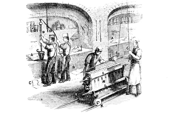
Fig. 1.—Gold Melting.
Fig. 1 represents the arrangements for melting the ingots with their alloy, for producing standard gold. In the Mint there are seven furnaces: each furnace, A, is 12 inches square and 24 inches deep to the top of the bars, which are seen at the ash-pit B. The pot C is made of a mixture of Stourbridge clay and plumbago, hence called a plumbago pot; it is 9¼ inches deep, and 7 inches across at the top inside. The pot, previously annealed, is placed in the furnace on a bottom which stands upon the two centre bars. The bottom is intended to shelter the base of the pot C from the stream of air which is necessary to the combustion of the fuel, but which would damage the pot. The pot is then covered by its muffle and lid, and surrounded by fuel, which, as it burns up, warms and then heats the pot to redness, but so gradually that there is no great risk of breaking the pot. When the pot has become of a full red heat, the ingots are carefully placed in it, and the alloy is added by means of the funnel I: the pot is then covered up, and allowed to remain till the whole mass of metal has liquefied. The foreman then stirs it with a rod made of the same substance as the pot, and allows it to remain till the fluid mass has reached a peculiar temperature, known by experience as that at which the metal, when poured into a mould, forms the most solid and workable bar. This temperature having been gained, the two outside bars at B are removed, the ash-pit is then covered to protect the men’s feet, and the firing poked out. The lid and muffle are next removed from the pot, and the pot lifted by an assistant from the furnace by the crane D. The foreman then conveys the pot C, by means of a pair of tongs which clasp it, to the frame of moulds, when an assistant brings forward a loop of iron, suspended by a chain and cord from the roof of the building, and passing the loop of iron over a button on the end of the lower clamp of the tongs, as shown at E, F, supports the weight of the pot by the cord, as indicated at G. Previously to the melting, pieces of charcoal are placed at the bottom of the pot for the purpose of reducing any oxide that may be present in the alloy—and Dr. Percy has found that copper can dissolve 13·50 per cent. of oxide of copper—because oxide of copper, when dissolved in standard gold, frequently renders the mass so brittle that when the bars produced are passed between the rollers they crack and break, just as does gold containing minute quantities of lead or zinc. The influence of oxide of copper on standard gold was thus very marked in 1859, when a large proportion of the gold was so brittle, that if a bar were dropped on the floor, or tapped with a hammer, it broke, just as heated brass breaks under similar circumstances. Mr. Richard Smith had some years since pointed out that if copper in which oxide of copper is dissolved be poured through an atmosphere of coal gas, all the oxide is reduced. I therefore submitted this gold to the process thus suggested to reduce all the oxide of copper, and produced bars so tough that they could not be broken by a sledge hammer unless after repeated bending by that means. Yet this gold was not thus cured of its brittleness, but was treated peculiarly, as will be seen in a future place.[10]
When the metal is fused, the charcoal which was placed at the bottom is brought to the surface by stirring, and as it rises through the fluid alloy, reduces the oxide of copper, and remains on the surface to protect the alloy from the action of atmospheric oxygen. In order to prevent it from falling into the moulds, the assistant holds a piece of stick at the mouth of the pot, thus allowing the gold to pass, but stopping the charcoal. The foreman, in the case of gold, judges almost wholly by the eye, but in the case of silver by the ear, as to when the moulds are filled. The metal poured from each pot forms four bars. The moulds H are made of iron, cast into such a form that each piece viewed from the top has the form of the letter T, so that three pieces placed together form two moulds; the whole of the set is held in its position by cross-bars, L, which fit into notches cut in the main frame M, where will be seen two powerful screws by which the moulds are forced tightly together after the cross-bars L are fixed. J represents the pots placed so as to be kept dry and ready for use; K, the wheels and tram on which the frame of moulds runs. The whole of the set of moulds having been filled, the screws at M are loosened, the bars, L, removed, and the parts of the several moulds removed, so that the bar in each mould is exposed to view. The workman takes each bar as it is exposed by a pair of tongs, and plunges it into a cistern of cold water to insure rapid cooling, and then places it on a bench, where the bars produced from each pot are separated and marked with a number, to indicate the pot from which they were poured, and the entire set with letters, to indicate the day on which the melting took place. After these distinctive marks have been placed on the bars, two assay pieces are taken from the bars from each pot.
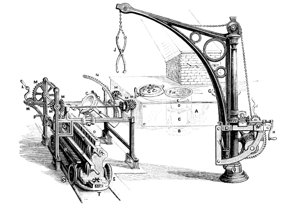
Fig. 2.—Silver Melting.
As silver melting,[11] when discreetly conducted, is slightly different in some of its details, it will be well to describe it here. In Fig. 2, A indicates the furnace with the front removed, to exhibit the internal arrangements. The furnace is circular, and is 21·5 inches across, and 31 inches deep. The bars, which are represented by dotted lines, are removable at will. The bottom B stands on the centre bars, just as in the case of gold melting: it is filled with coke dust, which retains any silver issuing from a small accidental crack or pin-hole in the pot, and also offers a non-conducting medium for the pot C to rest upon, it being necessary to avoid the abstraction of heat by the current of air against the base of the pot. A muffle, D, is placed on the pot, and upon this muffle the lid E rests. The pot is circular, and provided with a lip, to facilitate the pouring of the metal; it is made of wrought-iron, 12 inches across at the top, and 15 inches deep, and when melting for florins is charged with 4,800 ounces of silver. As in the case of gold, so with silver, the metal is alloyed with copper; standard silver being composed of 222 parts of pure silver and 18 parts of copper in 240 parts, or 92·50 parts of silver and 7·50 of copper in 100 parts.[12] The calculations based on the assays from ingots are just the same as in the case of gold. The ingots are put into the pot, and the lid is placed on the muffle (which is intended to prevent metal from falling over the top of the pot during the process of fusion, as sometimes might happen when scissel[13] is melted), and the furnace is then closed, so that the air enters through the bars, and passes into the chimney through the flue F. The lid of the furnace G is provided with peep-holes, by which the temperature can be regulated at will, while they also admit of a survey of the state of the furnace. When the fusion is complete, and carried so far as to raise the fluid metal to the necessary temperature, the bars of the furnace, with the exception of those which support the pot, are removed, and the fuel is poked out, because the pot at this temperature is so soft that it would be torn if it were pulled through the fuel. The lid and muffle are next taken off by tongs, and the crane is swung round by the handle, H, till its tongs are brought over the furnace, when, by working the handle I, the tongs J are lowered till they come to the pot; the foreman then makes them seize the pot, and by a signal gives his order for the raising of the pot from the furnace. Pieces of fuel and iron scaling are knocked off from the pot by the foreman with a brush kept in a crucible of water, indicated by V at the foot of the crane. The crane is then swung round by H, till the pot is over the cradle K, when it is lowered and secured in the cradle by the screw, shown at C. The frame of moulds is now run under the lip of the pot, and the foreman, by means of the handle L, which will be seen to communicate with the wheels M, and the rack N, tilts the pot so that the fluid metal may pour in a good stream into one of the moulds O, until, by the sound, he judges it to be full; he then lowers the pot, while his assistant, who is also watching the filling of the moulds, turns the handle P, which, by the wheel Q fitting into the rack R, moves forward the frame of moulds so far as to allow another mould to come beneath the lip of the pot, to be filled as before. The fluid silver in the melting-pot is covered with charcoal, for the same reason as explained in gold melting, and this is kept back by means of a large piece of charcoal laid at the mouth of the melting-pot. The frame of moulds runs on wheels S, and at T is provided with a rack and pinion, by which the moulds may be moved farther from or nearer to the lip of the pot, which, as it is tilted, is continually altering its relative position to the mouth of the moulds, and would, were it not for this arrangement, pour its metal outside of, or upon the moulds, instead of into them. The moulds are formed of T pieces, in the same manner as the moulds for gold, and are secured in their position by the same method, the cross-bars being shown at U. The bars, having been taken from the moulds, are cooled in water, and distinctively marked, as in the case of gold. Assay pieces are cut from them, but in the case of silver three assays are taken from the bars produced from each pot.
The bars for different denominations of coins are proportioned in their width, so as to admit of two rows of blanks being cut from the fillets produced from them. The following statement gives the whole facts concerning bars for each coin, as used in the Royal Mint. It would be well to produce bars of a uniform thickness of 0·50 inch, as such bars may be cast solid, and when cast produce better fillets with half the rolling, without the cost of annealing. There would be also another advantage, for the blanks obtained from the fillets produced from bars 0·50 inch thick would not require annealing, and would thus save the cost of that process, as well as the loss occasioned by it, while the coins produced would wear immeasurably longer in circulation. There are other considerations why this thickness should be at once adopted, as will be shown when the subject of loss by coining is explained.
I am glad to notice that Mr. Fremantle, in his Report on European Mints, proposes to adopt my recommendation, as shown by the following passage, page 9:—
“... It would seem to be a question whether in a newly organised Mint considerable time and labour might not be saved by reducing the size of the moulds in which both gold and silver bars are cast. The result would be that, as bars would be thinner when first subjected to the process of rolling, the time now occupied by that process would be sensibly diminished. It should also be mentioned that although there is great difficulty in producing sound castings if the thickness of the bars should be reduced, it might nevertheless, for the metallurgical reasons which Mr. Roberts points out, be advisable to make this alteration.”
There is really no “difficulty in producing sound castings if the thickness should be reduced;” but I fear there are many DIFFICULTIES in the Royal Mint itself. Indeed the casting of the bronze bars—whose thickness is less than that I propose for those of gold—gives evidence of the ease with which thinner bars may be produced; yet against these, insuperable difficulties were urged until I experimentally demonstrated how easily they could be cast.
Statement of Particulars as regards Bars used for Coining.
Metal. Denomination of intended coin. Length. Breadth. Thickness. Average Weight.
Inches. Inches. Inches. Troy oz.
Gold Sovereign 24 1·375 1·000 320
Half-Sovereign 24 1·125 1·000 250
Silver Crown 22 2·750 1·000 300
Half-Crown 22 2·500 1·000 240
Florin 21 2·125 1·000 220
Shilling 21 1·437 1·000 150
Sixpence 21 1·125 1·000 120
Fourpence 21 0·875 1·000 96
21 0·875 1·000 96
Bronze Penny 24 2·500 0·375 100
Halfpenny 24 3·000 0·375 117
Farthing 24 3·000 0·375 117
It is to be regretted that crowns, half-crowns, and fourpences are no longer coined. It has been represented to me by many manufacturers and others who employ vast numbers of men, that the disuse of the fourpenny piece has caused considerable inconvenience in the weekly payments to their workpeople. The objection to this coin would appear to be that it is so nearly the diameter of the threepenny piece; but this is obviated by the fact that the edge of the latter is plain, while that of the fourpenny is crenated or “milled.”
The assay pieces,[14] when cut from the bars, are placed in the divisions of a tray going from left to right, so that there can be no mistake as to the number of the pot from which the metal comes; each assay piece is then placed in a small envelope, marked with a distinctive mark, to characterise the pot from which it came. The assay pieces are sent in equal numbers to the two non-resident assayers, who determine, irrespectively of each other, the amount of gold found in each piece. Suppose we trace one assay piece, and imagine that 120 are undergoing the same process at the same time. The assay piece is flattened out into a kind of ribbon, and from it three pieces are cut, each weighing half a gramme. Each piece of this weight takes the name of a thousand, and is represented by the figures 1,000; but of course it may be called a pound, a ton, or by any other denomination. Each piece is wrapped in paper, with three times its weight of silver in two pieces, both metals being of the same thickness. The parcels, as they may now be called, are ready for the next process, and are arranged in their proper places from left to right in the divisions of a tray, and taken to the assaying furnace. In the assaying furnace is placed a Payen[15] muffle, or kind of oven, perforated at places so as to allow a limited amount of atmospheric air to pass from the interior through its sides into the furnace. The muffle is surrounded with fuel, so that it is kept at a good—almost white—heat. On the floor of the muffle is sprinkled some bone ash—obtained by burning bones to whiteness—and on this bone ash is placed a set of 40 cupels, or little cups, made of compressed bone ash, and about as big as a florin, and so deep as to hold about half a teaspoonful of water. When the cupels have been in the muffle long enough to become red hot, a piece of lead of about nine times the weight of the gold to be assayed is put into each cupel, taking care not to let any lead fall over, or it would destroy the muffle. So soon as the lead has melted, the paper parcels containing the gold and the silver are placed one in each cupel of melted lead. In a short time the gold and silver melt together, and, as it were, dissolve in the lead; then a kind of circulation of the fluid metallic mixture is observed to take place; and during this circulation, the lead, as it is presented to the surface, meets with the oxygen of the atmosphere, and combining with it, forms oxide of lead, which at that temperature is fluid, and drains into the substance of the cupel, carrying with it the copper and other impurities contained originally in the gold, leaving in the cupel a button which contains all the pure gold and the silver. The cupellation occupies about ten minutes, and at the end of that time the little mass of fused metal is observed to brighten up, the signal by which the assayer knows that the process is finished, and he withdraws the cupels one by one, tilting the fluid globule on one side, that it may incorporate with it any small globule which may chance to be upon the side of the cupel. Some assayers close the doorway of their muffles as the time of the brightening up of the assay approaches, to avoid the access of the atmosphere till the buttons have become solid, because the button of metal—by its silver—absorbs oxygen; and giving off this oxygen at the moment of solidification, spurts or opens, leaving the button hollow or ragged. This precaution is not thought necessary by all assayers, nor, indeed, is this system invariably followed, for some prefer to wrap the gold and silver in the lead foil which is to be used, and do not care to have the precious metals of identical thickness; these assayers use a smaller proportion of silver, viz., 15 parts to 6 of standard gold, or 17·50 to that which they judge to be fine, with a view to avoid the danger of “spurting;” they also save time by withdrawing the whole batch of cupels on a tray by means of a peel. The button is taken from the cupel as soon as it has been detached, either by dropping a little water on to it, or by allowing it to cool spontaneously, and it is then hammered out into a strip and annealed. It is next rolled into a ribbon or fillet, and again annealed, after which it is curled up into the form of a letter S. Some prefer to roll the piece into a kind of cushion, but in such a case it is more difficult to remove all the silver; the proper plan is to expose as large a surface as possible to the action of the acid in the next operation.
The S-shaped fillet is put into a flask of nitric acid of specific gravity 1·23, and the flask is placed in a little cup of brass, which stands over a small gas-burner, while the neck of the flask enters a kind of flue, through which a current of air is continually passing into the chimney of the furnace. The flask being placed in its position, the gas is lighted, and a gentle heat applied, when the nitric acid dissolves out the silver from the S-shaped fillet, and is known to have done its work when red fumes cease to be evolved. The acid is then poured off, and the remaining sponge of metal is washed with distilled water, and boiled with concentrated nitric acid, which removes the remainder of the silver. The sponge of gold is now washed with water, to remove the nitrate of silver, and is then heated to redness in a capsule to render it tough, for in its spongy state it is so rotten that it will not bear to be touched; and although it remains spongy, it is toughened by being heated to redness. It is now called a cornet. This spongy state is a consequence of the addition of silver, the presence of which, and its subsequent removal, produce a separation of the particles of the gold. The gold is thus formed into a kind of network or sponge, so that the acid can get at every part of it, and remove any metal which is soluble in the acid. Diluted acid is used first, because if there be any lead left it is dissolved out, and because the action of the strong acid is so violent, that part of it would probably be carried out from the flask. Nitric acid, when boiling, is liable to form bubbles of gas, which expanding, give rise to what is called bumping; hence it is usual to put a charred pea into the flask, and this, floating on the surface, causes a more even flow of vapour and gases, and so prevents bumping. It is probable that the charred pea determines the boiling at one particular temperature, for it is found that water, if it be floated in a fluid of a higher boiling point than itself, may be raised considerably above its ordinary boiling point, although remaining quiescent till disturbed by a rod or point. The cornet is next weighed, and as it has been begun under the idea that it was a thousand—1,000—all that it weighs short of 1,000 is the alloy which has been removed, the object having been to determine how much pure gold was present in the alloy. There is, however, a source of error in the process which requires to be explained.
It is found to be practically impossible to remove every trace of silver from the cornet; it is therefore necessary to make an allowance, the amount of which is determined by a proof. The proof consists of a mixture of gold and silver of known proportions, so that if all the silver be removed from a thousand—1,000—the remaining cornet should weigh exactly 916·6. Four of these proofs are worked with each batch of assays—a batch being 120 assays—under precisely similar circumstances, every precaution being taken that the four shall be equally distributed over different parts of the furnace, &c. Now suppose that the proofs, instead of weighing 916·6, as they would weigh if the whole of the silver were removed, were found each to weigh 916·9; it would be known that 000·3 of silver had been retained, and must be deducted from each of the whole batch of assays. If the assays of coins exceed the limits of from 917·6 to 915·6, they are repeated, as it is assumed that an error has arisen. The convenience of considering the ½ gramme as 1,000 consists in the fact that 1,000 parts of standard gold contain 916·67 of gold and 83·33 of alloy; so that the result having been arrived at without any calculation, one source of error is avoided and time is saved.
Messrs. Johnson, Matthey, and Co. have invented a tray of platinum capsules or thimbles, into which the assay pieces are placed for treatment with acid, instead of into the ordinary glass vessels over gas-burners. The advantages of this invention are too manifest to require elaboration; but saving of acid, gas, labour, and risk of error are amongst the chief of them; and besides, the plan has been in successful operation in their own assay offices in Hatton Garden, as well as in other important assay offices, for several years past. The first cost would seem to be the principal objection to this plan of Messrs. Johnson, Matthey, and Co.; but this is really a small matter, for the apparatus becomes stock in trade, and its cost should be viewed simply as so much capital, whose interest is paid by the saving effected in glass, but more especially by the smaller amount of acid actually employed, while the platinum can at all times be sold for nearly its original cost as old metal.
The mode of operation is as follows:—A stand of slate is so arranged that a means of heating is made to rest on its base. For this purpose a jet of gas is preferred; where, however, gas cannot be obtained, an ordinary oil lamp or a charcoal fire may be used. On a shelf over the source of heat are placed two or three receptacles of platinum, each communicating with a vessel made of porcelain, provided with three necks and an overflow pipe. There is a kind of sieve or tray of platinum, so arranged as to carry from 16 to 100 thimbles of platinum, and provided with a handle, so that this tray, with its charge, can be manipulated at pleasure. The thimbles vary in size according to taste, but each one is cut or slit at the bottom, so that the solution of silver as it is formed may by its density fall out, and allow the clean acid to take its place.
When an operation is to be performed, the tray filled with the charged thimbles—that is, containing the assay pieces—is placed in one of the platinum receptacles or boilers, and heated to a fitting temperature; when the desired effect is produced, the tray is lifted into another receptacle, and again heated; this may be carried to three times if necessary. The products of decomposition of the acid go, with the acid which evaporates, into the porcelain vessel, where the free acid falls through the overflow pipe into a proper chamber, while the acid fumes pass into the flue through the third neck before spoken of. The parted assays having been washed by several immersions in boiling distilled water, without removal from their thimbles, have now to be dried and annealed in a platinum muffle, so formed as to fit into an ordinary muffle, and, after annealing, to be weighed in the usual manner, having saved at least 75 per cent. of the usual trouble.
It is almost needless to add that the system of proofs above described must be also used with this process.
The assay for silver is not so tedious, as it is finished at the point where it leaves the muffle on the cupel; but up to this point it passes through precisely the same process as the gold.
It will have been observed that the event of the process of assaying is to exhibit the proportion of bullion which may be present in a given weight of mixed metals, but that it does not demonstrate the character of the substance which forms the alloy, because this is assumed to be copper or silver. In practice it is found that the alloy may be a mixture of copper or silver with lead, mercury, antimony, arsenic, tin, or zinc, in varying proportions, but whose sum does not exceed the rate per centum in relation to the bullion which is allowed by law. The existence of minute proportions of lead, mercury, antimony, arsenic, tin, or zinc is a matter of great concern, for these, when present, add indefinitely to the difficulties of the coining departments.
Under the present system, complete analyses of bullion imported for coining are a practical impossibility. I would therefore propose to abolish the office of non-resident assayer, and then to appoint two resident assayers, who should conduct their operations in independent laboratories—already existent—and a condition of whose appointment should be an agreement to conduct, when so directed by the Master of the Mint, complete analyses of the bullion submitted for assay. The information thus obtained would enable the melter, by processes subsequently explained,[16] to remove all those substances which are now found to be fatal to the coining of certain bullion. The appointment of officers possessing such ability would be an equal guarantee with the present for the faithful preservation of the integrity of the coinage. This suggestion has been adopted and recommended—so far as regards the resident assayers—by Messrs. C. W. Fremantle and C. Rivers Wilson, in their “Reports on the Mint,” 1870. Indeed two assistant assayers have been recently appointed.
When the assay reports arrive, the Master determines whether the metal has been found within the limits, and if he be satisfied he writes on the assay reports “Passed,” and signs the reports. The Deputy-Master retains the reports as his warrant, and then issues his order for the delivery of the bars by the melter to the rolling room, as recommended in my report dated 29th January, 1859; but, as the accounts are kept by weight, every set of bars is weighed by the officer who receives them into that room before he gives them to his men to work into fillets.
When, in 1856, I took charge of some departments in the Royal Mint, I found that the system of weighing was extremely loose. Officers were plainly told that if they ventured to satisfy themselves as to the weight of bullion they had received—in fact, to determine whether they received what was charged to them—“they would be paid out.” This state of things led men to accept any weight. But I objected and resisted; for I found that the average on each day’s work as received amounted to an habitual minus of five ounces on the weight charged on silver, while on gold it was seldom so little as one ounce. In illustration I will state one case which occurred. I delivered 7920·00 ounces of gold to the Mint Office. When that gold was received, the official weigher gave me credit for 7918·15 ounces, which was a deduction of no less than 1·85 ounces. I appealed to the Master, who by written order directed the gold, the weight of which was thus disputed, to be weighed by Mr. Pilcher, the officer of the weighing room, in the presence of witnesses whom the Master nominated. Mr. Pilcher complied with this order, and gave a certificate, signed by the deputed witnesses, in which he stated that the gold under dispute weighed 7919·98 ounces—that is, that it differed in weight as charged by me to the Mint Office 9·60 grains instead of 888·00 grains, the difference which the official weigher had deducted from the bullion I had delivered to him. The custom had been to weigh silver to 0·50 ounce, and gold to a pennyweight; but I introduced the system of weighing silver to 0·10 ounce, and gold to 0·01 ounce, and at the same time induced the Master to order new balances of superior construction for the coining department, and one specially devised by Mr. James M. Napier for use in the Mint Office. Of this balance, received after having been ordered for some years, it will be sufficient to say that it appears to be extremely accurate when properly used, and is then capable of great results; but, unfortunately, the system is such that those who are admittedly unfit may be promoted to important posts, just because they are senior, and not because of superior fitness for the work. This fine balance, therefore, becomes equal to a good rifle in the hands of a bad marksman. Great accuracy having been enforced, the weighing is now improved, but is still far from perfect, because the officers are compelled to abide by the decision of the weigher at the Mint Office, who, as beforesaid, may be unfit for his office, while the officers themselves are debarred from all checks, by the removal from the coining department of the set of standard weights, which were bought on purpose that those gentlemen might check their own weights as to accuracy. The Master’s order for the removal of these weights was in the following terms:—
“The standard weights hitherto kept in the weighing room are permanently transferred to the Mint Office. A new set of standard weights to be made for the Mint Office. The coining department weights to be examined by Mr. —— ——, and compared with those in the Mint Office (after these have been corrected), and reported on by him. Such examinations to be repeated every six weeks.”
It should be observed that this order was preceded by one written on the 2nd February, 1865, which directed that the Mint Office weigher should be the final judge, but that any officer might demand the re-weighing of any bullion, while the second weighing was to be final. All appeals to pass through Mr. John Graham, the order proceeding to direct that—
“The final decision is not to be called in question by any other officer of the coining department.”
The latter determination, I was informed, was intended to apply to me personally. Its immediate effect was a deduction of 0·25 ounce from the first gold I delivered, and a consequent alteration of my book to that extent by Mr. John Graham, who made a note in writing as follows:—
“This difference (error) may be accounted for by the acknowledged error of three grains heavy of the Mint Office 500 oz. weight. See Œrtling’s Report.
(Signed) “J. G.”
Such being the circumstances, I submitted; but the result could be in one direction only, for it had long been maintained that the reported losses were but “an hallucination,” and were, in fact, a “mere difference of weighing.”
It is true that the weights are periodically adjusted, but there is adjusting and adjusting. These facts have been dwelt upon because they have a most important bearing on the subject of loss and gain by coining, to be afterwards treated of.
Between 1856 and 1866 the old scales were removed, to make room for the superior balances of Messrs. De Grave, Short, and Fanner, the eminent scale-makers of St. Martin’s-le-Grand, of whose balances it is impossible to speak too highly, and of whom it is but fair to state that the Prize Medal was awarded to them at the International Exhibition, 1862, for their superior workmanship in balances.
Since it is necessary for the officer in charge of any department to ascertain the exact amount he gives to his workmen, and to satisfy the Master that they have returned—to within the limit of the weight of one blank of whatever denomination of coin he may be working—the bullion which they received, it became imperative to select the best balance; and in practice that made by Mr. S. R. Short, of the firm above named, was found to be the most serviceable. Mr. Short has introduced minor improvements from time to time, as experience has dictated, but the balance about to be described, after years of wear, determines to within one grain when charged with 1,200 ounces troy. The mode of proving the accuracy of a balance is to weigh as usual, and having arrived at a just determination of the weight of the matter to be weighed, to change the weights to the pan in which the matter has been weighed, and to place the matter in the pan previously occupied by the weights, so that both are now made dependent from the reverse ends of the beam; if the results be identical with the former results there can be no doubt as to the accuracy of the beam; should there be any variation, the balance must be adjusted by minute alterations of the knife-edges at its ends.
Mr. Napier has made his balance after the principle of Mr. Cotton’s balance, so that it requires no adjusting screws, but I have no personal experience of the benefits of this omission.
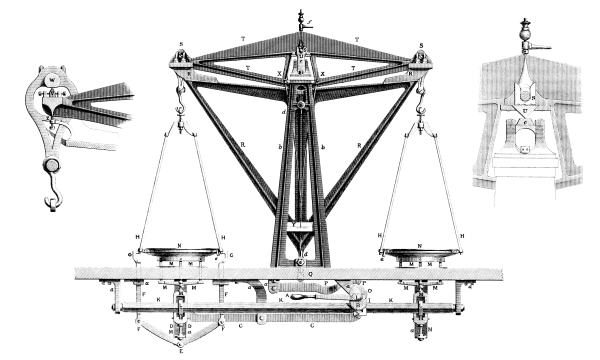
IMPROVED BALANCE (TO WEIGH 2000 OUNCES.)
BY Mʳ. S. R. SHORT, JUNʳ.
The balance used in the rolling room of the Royal Mint is specially adapted for the purpose. Such a balance, as already noticed, must be accurate, as must also all the balances used in the Mint; but this balance requires an arrangement by which the pans can be released from the beam and held firmly while being loaded. Mr. S. R. Short has been peculiarly happy in effecting this object, as will be seen by reference to the steel engraving, which exhibits a fine illustration of Mr. Short’s balance. The raising of the handle A causes the partial revolution of the cam B—represented by dotted lines—and this, as it diminishes, releases the lever C, which, by the rods D acting on the point E, permits the approach of the joints on the rods F towards the centre. The rods F work on a centre fixed beneath the table on which the balance stands, so that the closing of their one end causes the opening of the other. Thus the claws G recede from the wedges H, upon which they had been fastened, and so release the pan, for the claws act simply as a man’s hand would act in fixing the pan while it is being loaded. Immediately upon the opening of the claws another action takes place by the continued movement of the handle A, which causes the cam I to rotate upon the friction roller J, affixed to a lever proceeding from the shaft K, which at L is cut with eccentric bearings, so that by the partial revolution of K, caused by the pressure of I upon J, the series of supports M sink downwards from the pans N, thus obliging the pans, with the rods which support them, to be suspended from the supports S, which rest on the frame R. So soon as the pans are thus suspended, the continued motion of the handle A causes the cam O to permit the falling of the lever P, which at Q supports upon a friction roller the iron framework R. This framework terminates upwards at the points near S in sugar-loaf cones of gun-metal, which are intended to relieve the knife-edges of the beam from the pressure of their planes while the beam T is out of use, or while it is being loaded, for at these times the knife-edges would become seriously damaged. By the lowering of the frame R the centre knife-edge U is permitted to rest on its plane of steel c, which is beautifully bedded on an arch of gun-metal, as will be seen if the enlarged representation of this part, and which is shown to the right, be examined. In fact, the steel plane c is secured by wedges exactly shaped to it, but for the sake of illustration these wedges have been replaced in the enlarged portion of the engraving by upright pillars shown against c, with screws travelling through them, and intended to fix c rigidly in a given position. At the same instant that U comes into rest upon c, the knife-edges V at the ends of the beam T receive the planes W, so that the beam has now to support the weight of the matter placed in the scale-pans, and at this time is determined the actual weight of whatever that matter may be. The weigher, by an indicator suspended from the beam at X, reads the oscillations of the beam on an ivory plate at Y. At the time of weighing, the beam with its dependents is carried by the four-legged frame of iron b. The frame R passes through friction rollers of brass at d, which rollers maintain it in its relative position to the beam. The weighing having been determined, the handle A is reversed, and the beam is placed at rest; but the vibration of the machinery in the rolling room causes a continuous chatter of the knife-edges V against the planes W, therefore at each end of the beam a small screw Z is made just to touch the lower edge of the beam when it is at rest. Final adjustments which are very minute may be arranged by f; while the box e on the pan against G is intended to receive small pieces of lead, which are used to compensate for the loss by the wearing of the pans. The shaft K is supported from the table by a. The beam of the balance represented in the steel engraving measures 48·00 inches from knife-edge to knife-edge; that is to say, it measures 24·00 inches from the centre knife-edge to the knife-edge at either end. Mr. S. R. Short has made for the rolling room another balance for weighing silver, and as it differs in some important details, it is deemed wise to demonstrate those alterations in Fig. 3, where the supporting frame R will be seen to carry three upright pillars S¹, S², S³. The pillars S¹ and S³ are represented as being placed on the farther side of the beam, which at those parts is broken away, that the pieces of steel against which the pillars are made to touch may be seen. S² touches against one of these pieces of steel near the centre knife-edge U, and in front of the beam. The pillar S² terminates in a point, which passes into an inverted cone, while the point of S³ is made to pass into an inverted V, so that when the beam is raised by these pillars from its centre knife-edge, S² obliges it to take a specific position with regard to its distance from the centre of the plane on which its centre knife-edge rests, and S³ causes it to take a perfectly parallel line. S¹ is simply a plane which rises against a plane and steadies the other end of the beam, which by this arrangement stands as on a tripod, and is, therefore, prevented from moving, and in addition has its knife-edge invariably placed upon the same part of the plane at each time of weighing, while the frame R, by its continued lowering, drops the planes with equal accuracy on the end knife-edges V.
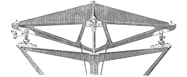
Fig 3.—Short’s Plan for Levelling a Beam.
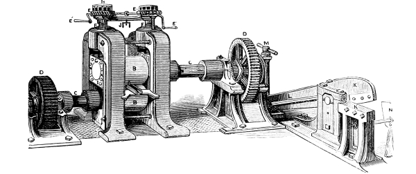
Fig. 4.—Breaking-down Mill.
The sovereign bars having been weighed by the officer, and given by him to his men, are wrought in sets of twenty; each set is called a batch, and each bar in the batch undergoes precisely the same process. The bar is passed into the opening A of the breaking-down mill Fig. 4, where it receives a considerable compression, for the rollers B, seizing its end, drag it forward, while they roll back and retard the progress of that part of the bar which is not between them. The result is that the bar is lengthened, but not widened materially, so that length is gained at the expense of the thickness, which is regulated by the distance between the rollers. The rollers are driven by shafts and adjusting couplings C, which are themselves driven by the wheels D. The distance between the rollers is determined by the action of the lever E′, which, by the endless wheels on its axle at E fitting into geared wheels, gives motion to powerful screws shown at F, which terminate in cups on the upper part of the upper brasses of the rollers B, as may be seen at G. The upper brasses are kept always against the ends of the screws by weights which are beneath the mill, but from which levers and rods terminate at the lower part of the upper brasses, at about the position indicated by I, so that the upper roller has motion either upwards or downwards at pleasure, but the motion upwards is arrested by the powerful screws F, and this point once determined by the reading of the scale H, is fixed by the clamp J. The thickness, therefore, of each bar in a batch is determined within certain limits; and when each bar in the batch has been rolled, the mill is altered, refixed, and again the rolling goes on till each bar has passed seven times at varying pinches through these rollers. Owing to the wear of the moulds in which the bars are cast—and which is largely due to the presence of minute portions of antimony in the gold—the bars are never of uniform thickness; hence bars of every denomination are passed through the rollers on their edge, so as to reduce them to one uniform thickness, otherwise the fillets resulting would be ragged, and of unequal widths, which defect would cause them to produce blanks out of remedy[17] as to weight. The rollers are set face to face; the graduated scale H is then fixed at zero; if now the rollers are separated until there be a space of 1·00 inch between them, the scale H will indicate 50; if, however, it be desired to read a higher figure, part of another revolution must be performed, causing the scale to read, say 31·50 of that revolution, when the rollers will be so far apart that sovereign bars which pass between them will, allowing for the expansion after compression, be found to be exactly 1·375 inches wide.
If now these bars be rolled on their sides, the mill must be turned down till the scale reads 45, when, if the bars be passed through, they will measure as under for width and thickness at each successive pinch. A spring-pinch means the passing the bar once more through the mill without altering the distance between the rollers.
A sovereign bar passed through the rolling mill— Becomes a fillet or ribbon—
Inches wide. Inches thick.
At 45·00 1·450 0·775
” 35·00 1·540 0·610
” 26·00 1·610 0·460
” 19·00 1·665 0·335
” 14·00 1·696 0·250
” 10·50 1·712 0·194
” 8·50 1·765 0·148
” 7·00 1·778 0·129
” 1st spring-pinch. 1·778 0·127
” 2nd ” ” 1·778 0·120
” 3rd ” ” 1·779 0·118
” 4th ” ” 1·781 0·117
When the bars have passed through the rollers at 10·50 they have become of great hardness, and of considerable length, say 6 or 8 feet. They are then taken to the shears K, where their hollow ends are cut off, and the bars cut into lengths of 18 inches; or rather, such was the practice when it was considered wise to obtain as much coined money as was possible from the bars; but recently, under other considerations, the old plan of the moneyers has been re-introduced, that of shearing the hollow ends from the bars before rolling. In this process there is needless waste, and it is to be hoped that the proper practice will be reverted to, for under that system the ends averaged 4·26 per cent., while under the re-introduced one it amounts to 7·03[18] per cent. on the bars, and for the following reason. When the metal is poured into the moulds, it almost immediately solidifies, and while solidification is going on contracts in volume, leaving a kind of cup of metal or hollow part on the top of the bar. In the act of rolling, the bar maintains an equable width until this hollow part is reached, when it suddenly expands, and at this point the workman shears off the defective part of the bar, whereas in the other case he shears off the hollow end until his eye fails to discover the effects of the shrinkage; hence the loss of 2·77 per cent. on the produce of fillets, as well as the loss in wages for melting the bars. The shears may be regarded as large scissors driven by a drum on the same shaft that carries the driving wheel for D. The drum is eccentric, so that at each revolution the shears are caused to open and shut. The bar being placed between the jaws K, the long end L of the shears is raised by the drum, and the piece is cut off. The shears may be closed and the end of L suspended, when out of use, by a hook on the end of the screw worked by the lever M. The length at which a bar is to be cut off is regulated by the gauge shown at N.
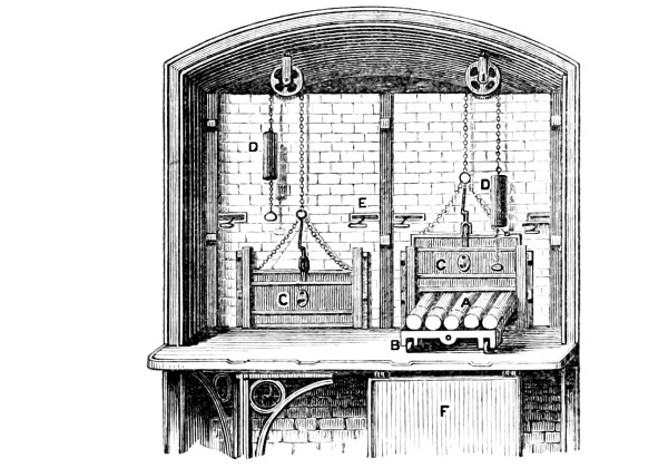
Fig. 5.—Annealing Furnace.
The sheared bars are placed in copper tubes, the tops of which are luted on with clay. It is imperative that the copper tubes should be made without solder, because this fuses at a temperature below that which is required to anneal the gold; if present it would run down upon the hot gold, and cause it to fuse and alloy with the solder, thus spoiling the work and entailing expense upon the coiner. The tubes which are used in the Royal Mint are made by Messrs. Benhams and Froud, of Chandos Street, Strand, who, after considerable pains, arrived at a method of making the tubes in such a manner as to entirely satisfy the requirements of the Mint. The tubes A are placed on an iron carriage B, which is then run into the furnace, as shown in Fig. 5. The door of the furnace C is closed by raising the counterpoise D; the heat of the furnace is regulated by the damper E. The apron F is sometimes of use in annealing very long silver bars. After remaining in this furnace for twenty minutes, the carriage is withdrawn, and the tubes, taken with tongs, are plunged into cold water, to cool the gold as rapidly as possible. The rapid cooling of gold and silver gives to each metal a peculiar character, which is of value in the after processes, and prevents the access of the atmosphere, which, in prolonged cooling, would cause the oxidation and consequent removal of so much copper that the alloyed metal would become too rich in gold for circulation as coin. The annealing of some metals is effected not so much by the continued heat as by the slow cooling; it is therefore wise to raise the metal to its full heat as rapidly as possible, and then so to arrange matters that it may cool very slowly. This method does not hold good in the case of the precious metals and of copper, for they become, under such treatment, so soft, malleable, and pasty as to stick to the machinery, and thus to cause considerable trouble and loss. After annealing, the bars, which are now called fillets, go again to the breaking-down mill, through which they are passed with the scale indicating 8·50, then at 7·00, and after this are submitted to another pinch without altering the scale at all; so that what is called a spring-pinch is given, with the intention of effecting the reduction of the fillet to one uniform thickness, for the breaking down and subsequent rolling cause the fillets to become much thicker in their middle than at their sides. The spring-pinches reduce this, while at the same time they diminish the elasticity of the metal, and fit it for the other mills. It will be seen, by reference to the above table, that the widening of the fillet is very trifling; but width may be gained to any desired extent, at the will of the workman, if the bars be submitted to a heavy pinch instead of a series of light ones. The fillet having been submitted to the fourth spring-pinch, is gauged on its side by a steel instrument, of which Fig. 6 is a representation. It is a hollow wedge, which is graduated to the thousandth of an inch. Supposing that the opening from A to B were extended until it were one inch wide at A, the space would be divided between it and B into 1,000 parts, and then every fillet passed into this opening would stop at a given point, say, for instance, at 140; such being the case, every part of the same fillet should be arrested precisely at the same point. The fillets are reduced till they measure 117 on this gauge, and are consequently 0·117 inches thick. They are then passed to the next mill, where they receive four light pinches, and then to a third mill, where they receive two more very light pinches, and by means of these six pinches are reduced in thickness to 0·075 inches. They then pass to another mill, still finer than any of the preceding, and here are submitted to four very light pinches, by which they are reduced to 0·058 inches, and are finally finished at the sixth or gauging mill, where they receive three pinches, and are then 0·053 inches thick by 1·829 wide.

Fig. 6.—Small Gauge.
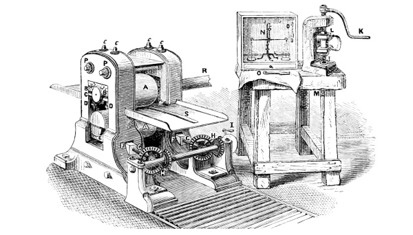
Fig. 7.—Gauging Mill.
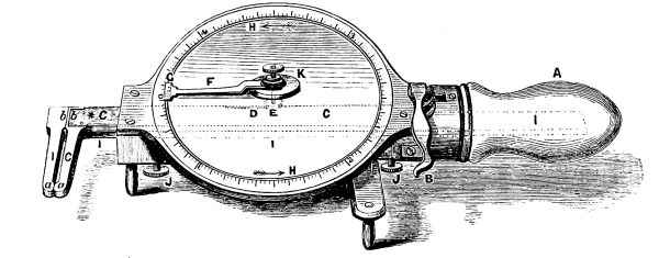
Fig. 8.—Ansell’s Standard Gauge.
The gauging mill is of different construction from the other mills, as may be seen by reference to Fig. 7, where the rollers A are seen in the act of reducing a fillet. The upper roller is fixed in brasses loosely clamped together; the upper brass, B, being firmly bolted to the main frame of the mill by the screws c, while the lower one C, which carries the weight of the roller when it is running empty, is supported by spiral springs shown at D. The lower roller works on a brass, E, which rests on a wedge shown at F; the brass being cut to fit the wedge, so that it may become similar to a solid mass, irrespective of any motion given to the wedge. By this mode of adjusting, a difference of the 0·001 of an inch may be made with ease between the distance of the rollers, and, consequently, in the thickness of fillets which may pass between them. The wedge F is moved forward and backward by the screw G, which itself has motion from the gear work H, by the handle I. Directly a fillet is passed between the rollers, the topmost one is forced against its upper brasses, and further upward motion becomes impossible. The weight of metal in this roller gives rise to irregularities in the thickness of the fillets which pass from this mill, causing much trouble and some expense; therefore it is proposed to support the upper roller by a similar arrangement to that which affects the lower roller, and to keep it rigidly against the upper brass, but with just so much pressure as its own weight would induce were circumstances reversed, and by these means to relieve the fillet from the weight of the roller, because that has an undue influence on each end of it. The gauger of fillets requires other tests besides that of the thickness of the edge of the fillet, so he punches out a blank from an occasional fillet by a hand-press, the cutter of which is shown at J, Fig. 7, worked by the handle K, through the screw L. The blank falling through the bolster of the cutter is caught at M, and is then weighed in the hand scales N, against a standard weight, from which it must not vary more than 0·50 grain. O, Fig. 7, is the gauge actually used by the workman; Fig. 6 represents the standard gauge used only by the officer in charge to check the work at its various stages. He has in addition a gauge of great accuracy, by which to measure the fillets at any point, as to width and thickness. This gauge will be more intelligible by reference to Fig. 8. A is the handle, which is hollow; B is a lever attached to the flat rod of copper C, which at D is cut with a rack, into which a pinion E is made to work. The pinion E works on a shaft, the upper end of which carries a hand F, provided with a vernier G. If now the handle A be firmly held by the hand, while the thumb be made to press the lever B towards the end of the handle, the rod C is set in motion, and causes the hand G to travel in the direction of H. The rod C rests on another rod I, made of steel, and so long as to pass into the handle of the instrument. The ends of the rods C and I are fitted at b with steel shoulders, and are then continued, as represented, to a. If it be desired to measure the thickness of a fillet, the points a a and b b are caused to open by pressure applied to B, and the fillet is placed between the points a, when a spring fixed in the box K brings back the rod C as soon as B is gently released, and encloses the fillet. The separation of the points a by the fillet causes the hand or indicator G to stand at a point from zero, which is then read. The scale is divided into 500 parts; and if the points be opened 0·50 inch, the hand makes one revolution; so that the ·001 of an inch is gained by one reading. But each 0·001 is subdivided by the vernier into ten, so that a ten-thousandth part of an inch is read without trouble. To measure the diameter of a blank coin, or the width of a fillet, it must be placed between the points b; but since the extreme graduation of this gauge is 0·50 inch, it is necessary, if it be desired to measure a larger diameter, to press back the lever B till the zero of the vernier G reaches 0·500 on the scale H, and hold it there while a clamp is made fast at the spot indicated by the star (*), to prevent the motion of C without I. When the clamp is fixed the rod I must be drawn out till the zero of the vernier reaches that of the scale H, when the screws J must be tightened to retain I in its new position, with half an inch permanent opening between the points b and between the points a. In a new measurement, that permanent 0·500 must be added to the reading. This arrangement admits of measuring up to 3·5000 inches, to which limit the gauge is extremely accurate. The instrument was invented by myself, because I found it difficult to convince the men that the fillet was thickest in its middle, and consequently heavier there than it should be; and, unfortunately, that the workmen habituated themselves to attributing this fault to each other, when its existence was proved. The fact was, that under the system which had prevailed, the men—with a view to make bad work for a specially-designed reason—would set the upper rollers at varying angles, so that a fillet at one mill would have one thin and one thick edge; and when that fillet passed through the next mill, the angle of the roller being altered, would make both edges alike, but the effect of the manœuvre was to push the metal into the middle of the fillet, and thus to unfit it for the draw-bench. Hence the necessity to fix where the blame should rest, and the production of this instrument, under my direction, by Mr. C. Becker, of 30, Strand, at once overcame all those difficulties.
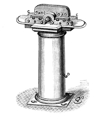
Fig. 9.—Small Shears.
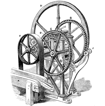
Fig. 10.—Flatting Mill.
The fillets are weighed from the rolling room to the drag room, where they are finally adjusted; for with every energy, discretion, and skill, FILLETS CANNOT BE OBTAINED OF UNIFORM THICKNESS BY SIMPLE ROLLING. In the drag room the fillets are taken to the small shears, Fig. 9, by which one end of each fillet is trimmed so as to render it square. The plates A are fixed to the head of a T-shaped lever, which is caused to oscillate by a cam beneath the floor. The plates A shut against a face of steel fixed to a block, and held by the screws shown at B; if therefore the end of the fillet be passed between the plate A and the face of B, each oscillation causes the cutting off of so much as protrudes, the pieces cut off falling into the box C, which has now been enlarged so far as to form a pan all round the top with a view to catch all of them. D forms part of a chain, by which the shears are thrown out of motion. The fillets, having been trimmed so as to render their ends square, are next passed to the extent of about two inches between the rollers of a flatting mill, shown in Fig. 10, which reduce that part of the fillet to about two-thirds its thickness. A A represent a pair of small rollers, the upper one of which is cut with three flat faces, so that it has three rounding and three flat surfaces; hence, when both rollers are revolving, there are spaces with openings between them; but when the rounding faces come down, those openings are much narrowed, so that any fillet placed between them becomes thinned to just such an extent as may be deemed necessary. The rollers travel in opposite directions, so as to cause the expulsion of a fillet placed between them. The reverse motion is gained as follows:—The upper roller is driven by B, which receives its motion from the little pinion C, carried on the shaft which also supports D. D reverses the motion of E, which is driven from the drum F. E also drives G, which gives motion to the lower roller. The fly-wheel H is borne at the extreme end of the shaft which carries F and E. The fillets are rested on J while being flatted, and are, after flatting, placed in the trough K, from which they are taken to a rolling mill in the drag room, of precisely the same construction as that exhibited at Fig. 7, to be passed twice through at equal pinches, with a view to render them still more accurate than they were when leaving the rolling room, as well as to reduce them to the exact thickness at which the trier has found they will produce the best work at the draw-bench. The rolling mill in the drag room was provided with steel rollers. Steel rollers are of somewhat recent invention, and seem to have received a high character from those whose opinion may be modified by further experiments more accurately made. My opinion, founded on experience, is to the effect that they are not worth their extra cost; but that their usefulness may be more fully developed when they shall have been fitted with the arrangements proposed for the gauging mills before explained.[19] After these alterations have been made, it may fairly be questioned whether steel rollers will, under circumstances every way similar, produce better work than is produced by the ordinary chilled-iron rollers; in other words, I believe that steel is not a better substance for rollers than chilled cast-iron. Those who have to sell, and those who have to use, have, of course, different motives; he who has to use a machine should judge calmly, and not be led away because the invention is new. It is amongst these considerations that I am convinced that steel rollers do not save money; for if they wear longer without getting out of order, they also require a longer time to put them again in order. Rollers, made from whatsoever substance, cannot reasonably be expected to produce a fillet from every part of which blanks of equal weight can be struck, because it is not yet possible to produce a compound of equal hardness throughout; but if the construction of the mill be altered, steel rollers may approach nearer to that perfection which is gained by the draw-bench, but they can never replace it. The fillets are taken from the mill to the draw-bench.
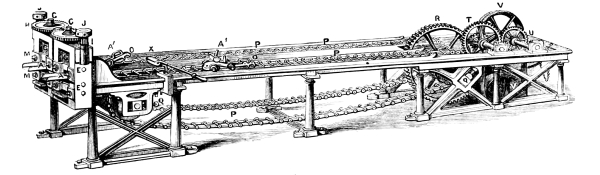
Fig. 11.—Draw-bench.
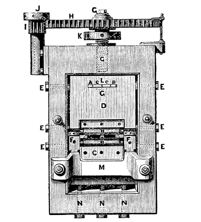
Fig. 12.—Head of Draw-bench.
Fig. 11 represents the draw-bench, the name of which is retained, as being in fact its only appropriate one. The flatted end of each fillet is passed into the opening shown at A. The dog A´ is then run up till its teeth seize the fillet. The lever is depressed until one of the hooks O catches a bar of the circulating chain P, which in its onward motion drags the dog, and causes it to bite the fillet and draw it through the opening at which it has been entered. P gets its motion from a notched cam, the axle of which is shown at Q. There are two distinct chains to each draw-bench, and there are two distinct draw-benches, so that one description does for both double ones. R is a cogged wheel, the shaft of which, Q, carries two notched drums, and each drum gives motion to a chain, so that both chains travel at the same pace. R is set in motion by the pinion S, on the shaft which is driven by the wheel T. T is driven by U, which is on the shaft driven by the strap and drums V. Fig. 12 is a representation of the head of the draw-bench, and in studying this engraving it will be well to refer at the same time to Fig. 11. The dog takes its name from its resemblance to the head of a bull-dog. It consists of a pair of levers, whose long arms extend beyond the axle-tree of the wheels nearest to O, and whose shortest arms are formed by the passing of the other axle-tree through the lever. The teeth are set at the front of the short arms. The axle-tree near O is fixed to the bars forming O, and runs loosely between the long arms of the lever, so that when O is pulled forcibly it causes the axle-tree to open the long end of the levers, and thereby to close the short end or teeth of the dog, the more rigidly in proportion to the pressure exerted at O. Directly the fillet has passed through the cylinders the dog springs slightly by the elasticity of the fillet, and thus releases itself from the chain; at the instant of release the weight over the foremost wheels falls, and by its fall lifts the hooks O so high as to admit of their escaping contact with the circulating chain P. The position of the teeth of the dog is shown by A in Fig. 12. The flatted part of the fillet is just so thin as to admit of its passing easily between the cylinders B until seized by A, but the part which is not thinned comes against the cylinders B, and requires considerable force to drag it between them. The cylinders B do not rotate; in fact, they may be considered as forming part of a solid mass.[20] The lower cylinder is laid on the bed C, and is clamped there by a cheek fastened on to C by three screws, the holes for which are shown on C; the upper cylinder is fixed to the mass D by a precisely similar arrangement. The beds C D are held perpendicularly by the points of the screws E; and we may now view the cylinders as secured to, and forming part of, their beds. The distance between the cylinders is regulated by the capstans F, which separate the beds of the cylinders, and so separate the cylinders. The accuracy of this adjustment is all-important, because the distance between the cylinders determines the thickness of the fillet which passes between them. The bed D of the upper cylinder is required to be movable at pleasure; it is therefore provided at G with four wedges, two of which, c c, are cut so that if looked upon from the top a round hole shows itself, and through this hole the end of the screw, which at this point L is plain, and has a neck turned in it, passes, with its head beneath the wedges and against the lower G. So soon as this is effected the wedges A B are pressed into their places, and these holding c c together, cause them to secure G by its neck; if, therefore, G be now caused to rise, the block D must rise with it, but the head of this screw rests on the solid block D, while its neck is just so long as to admit of this without itself being pressed against the wedges c c. G is a very fine-cut screw which fits into a female screw cut in the frame of the head of the draw-bench; it is moved to any distance varying from the hundred-thousandth part of an inch (0·00001) and upwards by the wheel H, which receives a very minute motion from the pinion I by means of a lever fitting into the capstan head J. K was originally intended to be used to set or fix the screw G when it had been brought to its proper position, but it is not used; for, in fact, the cylinders wear away appreciably by the passage of the fillets, so that they constantly require to be brought nearer together to make up for this wear. With some species of gold the friction is so great that, although oil is used, the cylinders become so hot as to render the gold pasty; in such case a kind of welding takes place, which causes the tearing of the fillet. If this extreme point be not reached, as indeed it seldom is, the cylinders become of varying temperatures, and so great is the effect of this, that in order to compensate for it, the upper cylinder has to be continually raised or depressed. The beds which carry the cylinders become worn by the strain and fret, and require grinding out at intervals; therefore, to allow for the difference which this would make, screws N are provided, by which the cylinder in the lower bed can always be raised to its proper position. We cannot but admire the ingenious productions of inventive minds; and surely if ever there were a marvellous machine for assisting the coiner, it is this; indeed, it may be doubted whether a more admirable instrument for its purpose can be contrived. Sir John Barton, who invented and directed the making of it, took into consideration every circumstance which could possibly arise, but he never saw practically the full advantage of his conception. Under my direction, this machine was so used that the average work produced was very favourably compared with the trials recorded by Sir John Barton, and details of which were given to me by the late Mr. W. H. Barton. There are some persons who smile at the draw-bench, but it is one of those inventions which will outlive its detractors, at least, so long as economy and perfection are points to be studied in coining. Foreign Mints are said to have found no advantage in the use of the draw-bench. It is to be regretted that they have not found a man with sufficient intelligence to use so accurate an instrument; it is surely not the fault of the sun if men are blind to its splendour. Mr. J. Martin, of the Paris Mint, has recently made some very accurate experiments with the draw-bench, and has produced results every way in accordance with those obtained by me in the Royal Mint, and is convinced that the draw-bench may be considered as the coiner’s right hand.
Against all sound advice the Master had been induced to buy a pair of steel rollers, at a cost of £800 (I state the sum on the authority of Mr. W. H. Barton, who, being Comptroller at the time, probably knew the actual cost), and with these I made an elaborate series of experiments, extending over many weeks. The results were wholly adverse to the new rollers—others arrived at the same conclusion—and I reported to the Master, in writing, on the facts as I found them, showing that the average gave an advantage of 19·92 per cent. in favour of the draw-bench, and on this ground I maintained the superiority of that machine. He replied by a peremptory order, directing me “to prohibit now and for ever” the “use of the draw-bench, and to take measures for its removal from the Mint.” Thus absolved from responsibility, I—after making a written protest—obeyed that which I could no longer withstand. The result was that the rejected blanks, which had averaged 3·60 per cent., now advanced to 23·52 per cent. I was unable to avoid this great expense, and when I spoke to him about it he was not very amiably disposed; however, he finally wrote me the following note, on which I remarked to him “that steel rollers, whether driven by cogged wheels or by straps, would still be steel rollers.”
“7th June, 1861.
“Dear Sir,
“In the cutting and adjusting room you may return to the use of the draw-bench till the gearing of the steel rollers is altered. I had overlooked the circumstance that in the United States Mint cogged wheels are not used for that purpose.
“Yours truly, “Tho. Graham.
“G. F. Ansell, Esquire.”
It is satisfactory to me to find that Mr. Fremantle confirms the opinion at which I had arrived. He says (“European Mints,” page 9):—“The adjustment of the fillets after rolling is in some European Mints performed by the draw-bench, as in England. In others it is performed by carefully adjusted rolling mills only. The experience acquired both in this country and abroad tends to show that it is advisable to retain the draw-bench—at any rate, until some more accurate method is found of equalising the fillets and reducing them to their correct thickness.” If Mr. Fremantle will investigate for himself instead of being guided by the opinions of others, he will rigidly follow the correct conclusion at which he has arrived; if, however, he will look in the drag room in the Royal Mint, he will discover evidence of the former existence of a series of rollers which were replaced by the draw-bench. Yet one of his co-travellers, who is manifestly willing to make experiments, says of the draw-bench, “Still it has yet to be proved that it can compete in sustained accuracy with a well-constructed rolling mill.” Quite true; but I think the answer holds good, and any one who would replace the draw-bench by rolling mills—which have hitherto failed—should, as Sir John Barton did, prove his proposition otherwise than at the Government expense, and then on success obtain fair remuneration. Before leaving the study of this instrument it is right that I should mention that Mr. John Murray, of the Royal Mint, has added immeasurably to the value of it by inventing a most ingenious machine for grinding the cylinders (see B, page 28) with accuracy, so that those cylinders which have been used can with ease be, as it were, repaired. In justice to Mr. Murray I should add that I omitted all mention of his invention in any former issue, because some principal contractors were to my knowledge intending to make him an offer of a sum of money for it, and under such circumstances I could not think it right to give a description of it. A like feeling induces me to postpone to another occasion details of this clever contrivance; its simplicity is such that a mere outline would put a maker of instruments in possession of means for its construction.
The fillets which have passed between the draw-bench cylinders are cut into lengths of about 18 inches by the shears shown at X, in Fig. 11, and are then sent to the trier, who by means of a hand-press similar to, but more delicate than, that shown at Fig. 7, punches out one or two blanks from each length of 18 inches, and weighs it, or them, against a standard weight, and in accordance with his judgment directs the fillets to be cut by the boys or men at the machines. The trier allows 0·20 grain on the pound of blanks for the loss which afterwards occurs by annealing.[21] If, however, the bars, as previously suggested, were cast uniformly of the thickness of 0·50 inch, this allowance, which is equal to a value of £34 8s. 7½d. on each million, need not be made; but in fact, as will be seen, even this is not sufficient to cover that loss under present circumstances.
Not only has it become a habit to smile at the draw-bench, but every unfair attempt has been made to get rid of it. Officers were abused because they would not report against it, and the machine itself was submitted to usage never contemplated by the inventor. The then chief coiner, who had formerly seen soap used in calico works in Manchester, insisted on using soap-suds, whereby the beds for the cylinders became rusted, the cylinders destroyed, and the whole machine thrown out of gear, so that 30 per cent. of all the work was rejected: these perverse trials, extending over weeks, appeared to throw discredit on the draw-bench. Having been a calico-printer, that officer endeavoured to engraft on to the processes of coining some of the practices adopted in that business; but had he duly appreciated the principle on which the draw-bench acts, he could not have attempted the use of soap-suds, or, at least, on its complete failure would have assented to its disuse. The very first object of the draw-bench is to produce just so much friction as will cause the lateral displacement of the molecules of the metal then under its operation. Soap, when it adheres to the bullion, permits the fillet to pass without friction, and when it is scraped off by the cylinders the gold becomes so hot from friction that the hand cannot with safety touch it; hence there are alternating parts of the fillet very hot and absolutely cold, and, as a consequence, no two blanks can be obtained of equal weight. Sir John Barton not only made the machine, but determined also that oil was the only fit lubricator for metal made to pass through the cylinders of the draw-bench. Forgetful of the immediate wear on the surface of the metal, others have attempted to replace the cylinders by wedges of steel, so made as that a constant stream of cold water should keep them cool when in operation. This also failed from the formation of rust, while the work produced never equalled that obtained from cylinders. The proper use of the draw-bench is to reduce fillets to an equable thickness in every part, and this can only be done when the trier, after studying the quality of his metal, has determined how much he can remove by once passing through the cylinders; then by keeping up a constant succession of fillets, properly smeared with oil, so that the equable friction always maintains them at the same temperature. Under such circumstances, and with a remedy of 0·24 grain, the rejected should not exceed 2 per cent., and this on the whole day’s work should contain half its weight of light and the other half heavy blanks. This also was a curious instance of want of knowledge on the part of that controlling officer, who for years maintained that if the work were properly conducted all the rejected should be on one side of the remedy.[22] The fillets, notwithstanding the draw-bench, cannot be brought to perfect accuracy, and to meet such variations as arise, a difference is made in two of the cutting-out punches by altering their diameters to such an extent that a blank cut by them from a standard fillet would vary in weight from a blank cut by a standard cutter from the same fillet. One cutting-out punch is so altered that a blank would be 0·125 grain, and the other that a blank would be 0·250 grain heavier. This admits of a fillet otherwise too thin being used; but if the fillet be found to err on the other side, it is passed once more either through the draw-bench, or through the mill at a spring-pinch. The trier, Mr. William Fenton, is a peculiarly steady man, possessing a calm judgment, with considerable energy, and upon him depends the accuracy of the whole process of coining; he has not unfrequently so managed his work that upon 5,000,000 of sovereigns coined, he has been within one sovereign of the calculated value.
The fillets, having been thrown by the trier into the receptacles which indicate the particular cutting-out punches to which they are to be taken, are fetched by a man, who wipes off the oil, and then carries them to the cutting-out room, where the fillets are cut into blanks and scissel. In this place it may farther be noticed that soap-suds cannot be used in the place of oil, because the soap could not be removed without washing,—a practical impossibility,—and would therefore remain, and add indefinitely to the weight of the gold, and thus open the door for peculation. The cutting-out presses used in the Royal Mint are very cumbersome, and when in operation are terribly noisy: it is therefore hoped that at no distant period they may be replaced by some of a far more simple construction; but it is believed that under all circumstances it will be found wise to adhere to the plan of cutting out a single blank at each descent of the punch.[23] For bronze it is well to obtain five or more blanks at each blow, but the limited variation of weight allowed by law on blanks of the precious metals would render this false economy. Fig. 13 represents one of the twelve cutting-out presses, which are all driven by the wheel A, provided with a series of cams on its outer rim; one of these cams, B, is in the act of striking the friction roller C, which is attached to, and forms part of, the lever D. D is fixed to an upright shaft E, which at F is cut with a screw thread working into a female screw fitted into the main shoulder of the press at G. If now the cam B strikes C, and throws it outwards, it causes the shaft E to take a part of a revolution, and in so doing the screw F makes it rise and carry with it the block H, whose tendency to circular motion is prevented by a plug fitting into its groove, and fixed in the guide I. The lower end of H carries the screwed cap J, which supports the cutting-out punch, so that when E rises it carries the cutting-out punch through just the same distance that itself travels upwards. The cutting-out punch is now ready for action, and is released by the continued revolution of the wheel A, as will be seen by the figure; but as it could not fall with sufficient force of itself, assistance is rendered by the pressure of the atmosphere, as will be seen by the following arrangement. The lever D is provided, near its junction at E, with a loop of iron travelling on a screw, so that it may be moved farther from, or nearer to, the centre of action, and thus admit of the increase of power. This loop of iron is represented by K, and is continued by a rod of iron across the upper part of the room and through a hole in the wall to a system of levers L, from which a rod is suspended, the lower end being connected with a piston working in the chamber M. The chamber M is an hermetically-closed vessel secured to a stone firmly fixed in the floor. The piston works in this chamber, and is covered with about two inches of oil, which prevents the access of the atmosphere by leaks to any part beneath the piston. If the piston, therefore, be raised from the base of the chamber, a vacuum is produced in that portion from which the piston is removed, and consequently the atmosphere presses on the surface of the oil, which in its turn presses on the piston, and carries it down (the reverse of the action explained by Mr. James Napier in “European Mints”); in its fall the piston pulls down the cutter, which has been raised; for the same blow which raises the cutter also raises this piston; therefore, when the cutter is raised the workman places the fillet N, from which blanks are to be cut, on the bolster, shown at O, and holds it firmly while the cutter descends and punches out a blank, which falls through the bolster into the drawer P. By the time that the down stroke of the cutting-out punch is complete, the wedge Q has entered a slit in the spring R, and strikes the spring, thus throwing the machine back, and preparing it to start when the cam B shall strike the friction roller C. The point at which Q may strike R is determined by a screw near the left-hand T. The upright shaft E, which is partly hollow, terminates at a flat cogged wheel, and the upper part of F is made to pass into E; while at S is an arrangement which serves to detach or connect these pieces, that the cutter may upon occasion be used by the hand by means of the lever T, as well as to admit of the necessary alterations, as the punches, by regrinding, become shorter. The cutting-out punch, when it rises, carries with it the fillet from which the blank has been punched, until the fillet comes against the guard W, which detaches it.