VII FURNITURE MAKING
Reading edition
It is only by labour that thought can be made healthy, and only by thought that labour can be made happy—John Ruskin
The chief purpose of this chapter is to outline the most important general facts upon which good furniture making is based and to give specific directions for working out a number of typical problems, following designs which have been proved in completed articles made, for the most part, by school-boys and tested by use. No attempt is made to give this great subject complete and systematic treatment; for this would involve many problems in constructive design and a corresponding number of working drawings, with specifications for the selection and preparation of materials and for the work of construction—a subject so extensive that it would easily overrun the limits of a single chapter. The aim is rather to select a few of the most suggestive lessons of experience in constructive work with special reference to our main subject of household decoration.
It is taken for granted that the interested reader is familiar with the use of the common hand tools for woodworking or that he can, with some assistance, perhaps, easily command their use. It is not thought necessary, therefore, to describe in detail the proper method of using tools, but rather to offer practical suggestions on the selection, preparation and constructive use of woodworking materials and, in the series of problems which follow, to give some helpful hints on the way woodworking tools should be used. It is also assumed that in most cases the very great advantage of woodworking machinery may be utilized, especially in preparing the materials and bringing them within easy reach of the hand-tool processes. The true art-craft spirit, which always honours handwork as the supreme method, may not hesitate to command the services of machines so long as it does not become slavishly dependent upon them.
SELECTION AND PREPARATION OF STOCK
The first thing that should claim the attention of the artistic woodworker is the selection and preparation of his materials, commonly known as the stock. The sculptor selects his marbles with the greatest care. So should the cabinet-maker make sure that his woods are taken from the right parts of selected timber and that they are properly sawed and well seasoned. The importance of this cannot be overestimated. Hard wood boards, cut from the sides of a tree, will in drying, invariably curve across their grain. It is only those that are cut from the centre to the outside of the tree that may be depended upon to remain approximately true; for, after this cutting, the grain runs directly through the thickness of the board, or nearly so. Boards taken from timber in this way are said to be "quarter sawed"; those cut by sawing through the logs from side to side, as is always done with soft woods and often with hard woods, are said to be "plain sawed." This is illustrated in the accompanying drawings.
Quartered Oak.—In the case of oak, the quarter sawing not only maintains a flat surface but greatly improves the appearance of the stock when finished. The popularity of quartered oak for furniture may therefore be said to be well founded, for it is the sincerest of woods. It is as good as it looks.
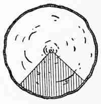
Quarter sawed log
Quarter sawing, however, is very largely confined to oak because the appearance of the grain and the strength of most woods is far from being improved by this method of cutting. Thus ash and gum wood and all the softer woods sometimes used in furniture making are plain sawed. We shall, therefore, generally find stock from these woods curved and twisted badly so that it will be necessary, in selecting material for large surfaces such as table tops, to pick out the straight parts for these surfaces and save the remainder to be cut into the smaller pieces which will always be needed. These pieces can be easily planed without much loss of thickness.

End of quarter sawed board
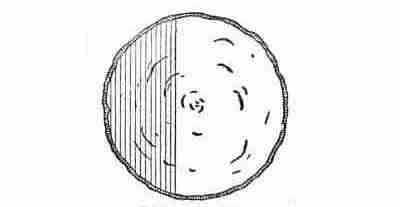
Plain sawed log

End of plain sawed board
Kiln-dried Lumber.—This bending and twisting of the boards does not take place as soon as they are sawed out of the log, but gradually during the process of seasoning; and, unless the lumber is kiln-dried, the more gradual the seasoning the less the bending. Lumber is kiln-dried by stacking it, with air spaces left between the boards, in steam-heated closets or kilns, where the process of drying is carried on evenly though rapidly. Kiln-dried lumber, therefore, retains its shape quite as well as that which is dried slowly in the lumber pile. But whether kiln-dried or not, it should be allowed to remain in a dry place as long as possible before using it so that it will have a chance to change all that it is likely to and so lessen the subsequent shrinking and warping. A good cabinet-maker never undertakes to make furniture from stock that he does not know to be perfectly dry and well seasoned, not only because unseasoned lumber is more likely to shrink, warp, and crack, but also because it cannot be depended upon to hold the glue, take varnish well, or respond readily to other methods of finishing.
Planing Down to a Flat Surface.—Since boards are seldom perfectly flat, even if one has taken the greatest pains to select well-seasoned stock, it will almost invariably be necessary to work them down to a plane surface when they are glued up or joined together in any way. To accomplish this result it is necessary to plan the arrangement of the pieces in such a way that the concave of the bend shall fall on the same side, as shown in the illustration, and thus provide for the final working down with the least possible removal of stock. They can be arranged on a level bench top or floor with the convex side down so that they will lie as flat as possible. The boards should then be taken out one by one and their edges should be carefully planed so that they will match together in the position in which they are laid. It will be necessary to take each board from its place and return it several times in order that this matching may be made as perfect as possible. The object of all this is to prevent the entire arrangement from springing—i. e., from acquiring any new bend or twist when the parts are glued up. In joining boards to form large pieces of glued-up work, like table tops, it is customary to strengthen the joints by means of dowel pins. Small table tops and similar work may be safely glued up without dowelling.

Boards placed for planing to flat surfaces
Fastening Glued-up Work. It will be readily understood upon a little reflection that all plain glued-up work should be allowed to move slightly upon the framework to which it is attached; for even after it is well seasoned and well finished all woods will swell slightly in a damp atmosphere and shrink slightly when the air is dry, the greatest movement being across the grain. Solid table tops, therefore, should never be fastened down firmly upon the framework with glue or with screws, but should be secured by means of buttons screwed to the under side of the top which travel in grooves cut in the framework and thus allow for expansion and contraction. A drawing is shown to illustrate the method of attaching the table-top buttons. Much of the warping and splitting of furniture is due to the failure of the designer or maker to observe this precaution.
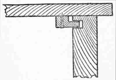
Method of fastening table tops
In planing up stock, whether it be a single piece or several glued together as just described, the cabinet-maker planes off one side first and then, using this side as the working face, gauges to the required thickness and planes off the other side if necessary. If the work be upon glued-up stock, it is well to plane off the projecting edges of the concave sides first, as that is generally somewhat easier and may be all the planing that will be necessary. If it be single pieces of stock that need to be planed up, the natural twist or "wind" is first planed out to a flat working face on one side before putting the plane to the opposite side.
The Surface Plate.—Planing to a flat surface requires some device to guide the eye. If the surface be very uneven at first, a beginning may be made in the planing without much assistance; but a point will finally be reached when neither the unaided eye nor the hand can determine whether or not a surface is flat. To determine this a surface plate, as it is called, is needed. This consists of a block of cast-iron, thick enough to prevent it from being bent—i. e., an inch or more—and with a somewhat rough but perfectly flat surface on one side. This surface is well chalked over. When the wood surface which is being planed down is laid upon this chalked surface and slightly moved it is readily seen that the highest places on the wood will become marked with the chalk and so indicate to the cabinet-maker what parts are to be removed. By making several tests of this kind he is able to plane to a good flat surface.
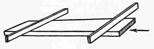
Winding sticks
Winding Sticks.—If the amateur's workshop is not provided with a surface plate, a simple means of testing for a flat surface is by means of two narrow straight edges or "winding" sticks, placing them on their narrow edges across each end of the piece, as shown in the illustration, and sighting across their upper edges. The slight projections in the surfaces of the board can be determined in this way and planed off until the two top edges of the sticks are found to be level. These winding sticks are simply wooden strips, accurately made, with opposite faces parallel. Their dimensions may be 1 × 21⁄2 × 30 inches.
Importance of True Surfaces.—It may be well to add that all this care to produce flat and parallel surfaces is not merely for the purpose of giving a good appearance to these surfaces. True surfaces are necessary for the good of the work as a whole, for they form the basis from which other surfaces are gauged and other parts "trued up"—i. e., made square or otherwise geometrically correct. When the main surfaces of a piece of cabinet work are properly shaped, all the framework and other parts may be brought into line without bending or twisting. All such strains should be religiously avoided in good cabinet work. The natural curves, twists, or projections of the stock used should be removed by the use of the proper tools and never be strained to force any of the parts into their proper places or shapes. Such efforts produce strains which are transmitted to other parts, displacing them, causing new defects or a general failure of the parts to support each other.
A Systematic Plan of Work.—When the cabinet-maker undertakes to make either a single piece of furniture or several pieces, he goes about it in a very systematic way. Consulting his working drawing he makes an accurate list of the different pieces that will be required. For example, if he is to make a Morris chair he notes the fact that he will need four legs or posts 21⁄2 inches square by 223⁄4 inches long, a front rail and a back rail each 7⁄8 × 21⁄4 × 22 inches, two side rails 7⁄8 × 21⁄4 × 24 inches, and so on until the list of necessary parts is completed. With this list in hand he makes a careful selection of the lumber and prepares the pieces in the rough, allowing economically for the necessary working waste. Economy of time and labour is also secured by keeping together all parts on which similar work is to be done. Thus, if several parts are to be sawed to the same width or fashioned to the same curves, it is generally the best plan to work these parts out together while the machines and tools are set for this purpose. Such a plan not only saves time but, partially at least, it obviates the danger of mistakes. It is important also to follow a systematic order of work. All sawing to rough dimensions should be done before the pieces are dressed to drawing dimensions, and the latter operations should generally all be completed before laying out and cutting the joints. As the work progresses toward completion great saving of time and much comfort will result from keeping the completed parts in good condition and so arranged that they can be easily assembled.
GLUING
Necessity of Good Joints.—After the selection and preparation of the material for the stock, the next important general process that demands attention is gluing; for good cabinet work implies good glue and a knowledge of how to use it. Prepared glue, such as is sold in bottles, is unsatisfactory for work of any consequence. A good woodworker always has his own glue pot and sees to it that it may be made ready for use on short notice. The glue should be fresh, thin, and hot. It should be applied quickly in a warm room and the parts to which it is applied clamped up quickly before the glue chills. It is the glue which penetrates the wood that holds the parts together and not a layer of glue between the joined edges or surfaces. It is therefore evident not only that joints and surfaces should be well smeared with glue, hot and thin enough to be quickly absorbed, but also that the parts should be clamped up quickly while the glue is still hot so as to prevent any surplus from remaining in the joint. This is an additional reason for making close fits in all joints—in those which are to be glued up as well as in those which are not. It is a common fault of beginners to be satisfied with loose mortise and tenon joints, counting upon the glue to fill up the spaces. Much of the furniture found in the markets falls to pieces for the same reason. Such work should never be allowed to pass. It is based upon an entirely mistaken notion of the true office of glue and is nothing more nor less than a falsehood in wood.
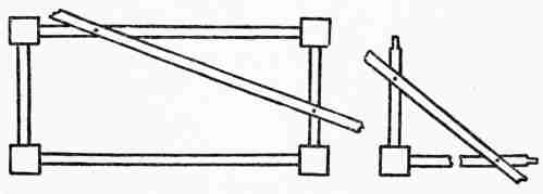
Method of holding framing parts square while glue is setting
Systematic Methods Required.—As in the preparation of stock and working it up, so in gluing, system is all important. The hand screws or clamps should be made ready and adjusted to the required width so that they may be quickly placed in position as soon as the glue is applied. The whole process must be managed as quickly as possible because the joints must be tested before the glue has had time to set. A carpenter's large square should be used for testing the right angles, since it is more reliable than the small try squares. It will frequently be found necessary to hold framing pieces square while the glue is hardening. This can easily be done by nailing small strips of waste stock across the parts, as shown in the drawing. A beginner should be cautioned not to attempt to glue up too many joints at one time. Two opposite corners of a framing piece should be glued up separately and left to set before the attempt is made to glue the whole rectangle together. The two remaining joints, however, should be glued and clamped together at the same time.
PICTURE FRAMING
Inexpensive Framing Stock.—Picture-frame stock can be easily obtained of dealers in artists' supplies and in furniture stores in a great variety of styles. Much of it is so well prepared and so nicely finished that it leaves little to be desired. It is, therefore, often best to secure the stock for frames in this way. It is, however, somewhat expensive, so that, when economy is important, it behooves the young woodworker to prepare his own framing stock.
Very satisfactory frames 2 inches in width or less may be made from matched oak flooring, a section of which is here illustrated, by planing off the tongue and cutting away one side of the groove to furnish the inset for the glass. Wider flat frames of any thickness can, of course, be cut out from the ordinary stock. A special tool for cutting the inset is desirable but not necessary. A 1⁄4-inch saw cut may be made with a circular saw or even with a hand saw and the necessary removal of the wood accomplished by means of careful chiselling.
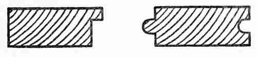
Picture framing stock made from oak flooring
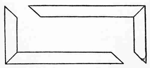
The mitre joint
Mitres.—Frames may be joined at the corners in various ways. A common way is by the mitre joint illustrated in the drawing. To secure good joints of this kind it is necessary that the mitres be cut on an angle of exactly 45 degrees and that the pieces for the corresponding sides of the frame be precisely of the same length. Hand sawing is generally not exact enough to produce angles of sufficient accuracy even when an ordinary mitre box is used. Hand-sawed mitres, therefore, will require a little truing with a small plane. Great care must be exercised also in fitting the corners together. The common bench square is not large enough to prove the work. A better way is to lay a carpenter's framing square on the bench and fit the two pieces of the frame against the sides of the square, testing each corner in that way.
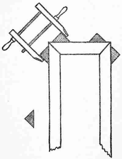
Clamping mitre joints
Gluing the Joints.—If the corners are unusually well fitted, a good joint can be made by first sizing the ends with glue and then firmly pressing the pieces together upon a true surface, leaving them undisturbed for four or five hours until the glue is hard. By sizing the ends of the joints is meant thoroughly filling the end pores with glue, rubbing it into the pores with another block. Generally speaking, however, it is necessary to make use of a mitre-clamping device. If a special clamping device is not available, one can be easily made by gluing small soft wood blocks to the parts of the frame near the corners, as shown in the accompanying drawing. In a half hour or so these blocks will become firmly set so that the mitre joints may be glued together, clamping them up with a hand screw. As already explained under the general directions on gluing, it is good practice for a beginner to glue up opposite corners and not attempt to glue up the two remaining corners until the first two are well set. When the first two corners are well set they should be nailed; and before the two remaining corners are glued it is well to try the parts together to see if they do not require a little correcting before gluing. These joints also should have light nailing after the glue has been set. In nailing, small holes should be made with a brad awl or drill in order to avoid splitting the corners, and long finishing nails should be used.
The Defect of Shrinking.—With proper tools the mitre joint is the easiest one to make, but it has one unavoidable defect, especially in wide frames. It is very difficult to get stock well seasoned and almost impossible to get it perfectly seasoned, so that wide frames, however well finished, must be expected to shrink a little after they are joined together. As most of this shrinking is across the width of the stock it is evident that it will tend to open the mitre joints on the inside of the corners. This is what happens almost invariably with joints made in this way from wide stock in picture framing. The same defect is also frequently observed in the interior finishing around windows and doors.
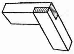
Halved lap joint
There are three other methods of joining the corners of picture frames—viz., the halved lap joint, the mortise and tenon joint, and the dowelled joint. A drawing is shown to illustrate these three kinds of corner joints, and it is hardly necessary to say that no one of them is open to the same objection that attaches to the mitre joint. All these joints require accurate cutting and rather more of it than the mitre joint requires, but they are more easily glued up. The halved lap joint is easily clamped up with a common hand screw, even when the frame is a very large one. But the other two require long clamps in order to pull the joints up well.
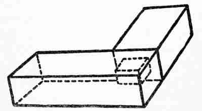
Mortise and tenon joint
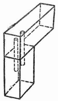
Dowelled joint
Character of the Frame.—The kind of joint required depends upon the general character of the frame—whether it is to be heavy or light, wide or narrow, and whether made of picture frame moulding or of the plain framing stock with round or flat face; and the character of the frame is a matter of design, determined by the kind of picture, by its setting, and by other considerations discussed in Chapter III. How the plan for the construction of the frame for any given picture is influenced by such considerations may be seen in the example which follows:
MAKING A FRAME FOR A LARGE PHOTOGRAPHIC REPRODUCTION
This photograph is 60 inches long by 16 inches wide. It is a copy in brown tones of a classic painting by Otto Kneille—The Education of Athenian Youth, the original of which hangs in the Royal Gymnasium in Berlin. It represents a spacious hall or court showing three of the large marble columns and a massive seat in which an old man reclines while another old man is expounding some doctrine to him and to a group of younger men gathered around. In the centre of the scene a boy lies flat upon the pavement reading a manuscript. Near him several youths under the direction of a master, are contending in feats of strength. The composition is one that suggests weight and power. It may appropriately hang in the hall or in the library over a wide, low bookcase.
A picture of this character needs no mat and must have a wide, heavy frame. The stock chosen was oak, 4 inches wide, 11⁄2 inches thick, and flat faced. The size and weight of such a frame, including the glass, demand firmness of construction as the first consideration. The stock is too wide for successful mitring because shrinking would naturally open and weaken such joints. It was therefore framed together with mortise and tenon joints, well glued. A dowelled joint might have sufficed, but it would not have the same strength. The mortises were cut in the vertical ends and the tenons were left on the long horizontal pieces. This was in conformity with the usual method of joining framework—for example, door frames, window frames, panel frames, and other interior woodwork; for the greatest possible length is invariably given to the vertical parts.
The frame was given a dark brown finish, repeating the darkest tones of the picture. Long screw eyes were fastened to the back 2 inches from the top, so that the picture might hang nearly flat against the wall. A strong braided wire about 75 inches long was run through the eyes and securely looped at each end, so that a little more than an inch of wire on each side passed through the eyes. Since the picture was to have a prominent place on a certain wall, two nails 66 inches apart allowing for the two widths of the frame as well as for the length of the picture were driven into this wall, and the heavy photograph was easily hung and balanced without exposing the wire to view.
TO MAKE A KNOCK-DOWN BOOKCASE
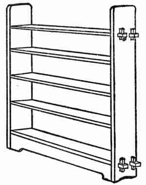
A knock-down bookcase
The Design.—The problem of design was to plan a simple, inexpensive bookcase which could be easily transported and set up in a student's room and which would hold approximately two hundred books. The drawings show how these requirements were met in the design. When in use it is held together by keyed shelves at the top and bottom. The necessary stiffness is given to it by the base pieces which are fastened both to the sides and to the bottom shelf by screws. Additional stiffness is given by drawing up the three middle shelves to the sides by means of screws. Upon removing the screws and the keys the bookcase is easily taken apart so that it may be crated in compact form for transportation. It is equally easy to set it up again. It has no back and may therefore stand away from the wall as well as against it. Its contour is plain, with few curves, giving a simplicity which will harmonize with modest surroundings and yet not bar it from keeping company with more pretentious furnishings.
The original of this design was actually made up in white wood, stained and finished to harmonize with black walnut furniture; but it may be made up in oak, ash, cherry, or any of the common woods used for furniture. For one bookcase the stock required is as follows, the sizes allowing for finishing to the dimensions as given in the drawing: For the ends, two pieces 7⁄8 inch × 101⁄4 inches × 4 feet 21⁄2 inches; for the short shelves, three pieces 7⁄8 inch × 101⁄4 inches × 3 feet 1 inch; for the long shelves, two pieces, 7⁄8 inch × 101⁄4 inches × 3 feet 5 inches; for the base pieces, two pieces 7⁄8 inch × 63⁄4 × inches × 3 feet; for the keys, one piece 7⁄8 inch × 7⁄8 inch × 1 foot. In addition to this there should be two dozen No. 10 round-headed blued screws, and one half dozen 11⁄2 inch No. 10 flat headed blued screws.
The tools needed are as follows: Rip saw, cross cut saw, back saw, compass, jack-plane, smoothing plane, block plane, spokeshave, try square, steel square, rule, knife, hammer, mallet, screw-driver, 3⁄4, 1⁄2, and 3⁄16 inch bits and bitstock, and 1⁄2 and 3⁄4 inch chisels, gauges, and sand-paper.
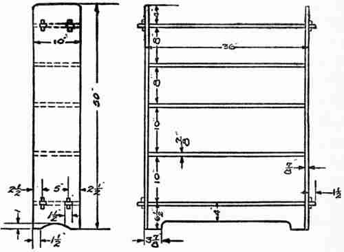
Details and dimensions for a knock-down bookcase
Construction.—All the stock should be jointed, planed to width, and smoothed with sand-paper. The two end pieces should be squared to length, the top corners rounded, and the curve at the bottom cut as shown in the drawing. Care should be exercised in sand-papering not to round the edges. The correct spacing for the shelves should then be marked off on the end pieces and squared across, care being taken to have both ends spaced alike. To do this plane the ends together, with their edges flush; and, beginning at the bottom, measure off each of the spaces with correct allowance for the thickness of the shelf and mark these spaces across the edge. Then, separate the end pieces and with the marks on the edges as a guide, square across each of the end pieces on the inside and mark with a knife. In allowing for the thickness of the shelves it should be remembered that the stock, though originally 7⁄8 of an inch in thickness, has been planed and sand-papered, some of the shelves perhaps having been finished down more than others. It will therefore be necessary to measure and allow for the thickness of each shelf separately.
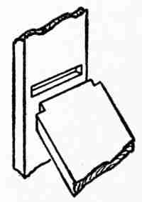
Method of gaining-in the shelves
The three middle shelves are "gained" in—i. e., set into grooves in the upright ends—1⁄4 of an inch deep, as shown in the sketch. It will be better craftsmanship if the grooves are not carried across the full width of the end pieces but stopped, say, one inch from the edge, the shelves being cut to fit, as shown in the drawing. If this be done, the grooves should be cut out carefully with a chisel. If the grooves be carried across the full width of the end, they may be cut down with a back saw and then chiselled out. To insure a good fit in either case care should be exercised not to cut outside the knife lines. Chisel the bottom of the grooves carefully so that they will be uniformly 1⁄4 of an inch deep.
The next step is to cut the mortises for the top and bottom shelves. The dimensions for these should first be laid off on the stock by means of a gauge. They should then be bored well inside the marks and carefully chiselled out. Before this chiselling is done, however, knife lines should be marked on the outside of the end pieces exactly opposite the gauge lines. In mortising, as in cutting the grooves, the greatest care will need to be exercised that the chisel does not cut outside the knife lines. In working for a close fit it is better to err on the side of removing too little stock at first, if one must err at all, since it is quite easy to remove a little more in the final fitting. It is quite impossible to replace stock once removed.
In measuring for the length of the shelves it should not be overlooked that the top and bottom shelves are to carry the tenons to be keyed through the end pieces. These tenons should be cut out accurately with a rip saw, and the stock between them removed with a chisel after a deep knife line has been made. After fitting these tenons to the mortises and finishing them, the mortises for the keys should be cut, using a small chisel. It should not be overlooked that the outside face of each key mortise is cut on an angle, as illustrated. The three middle shelves are then cut to length, the ends squared by means of a block plane, and corners cut out to fit the grooves.
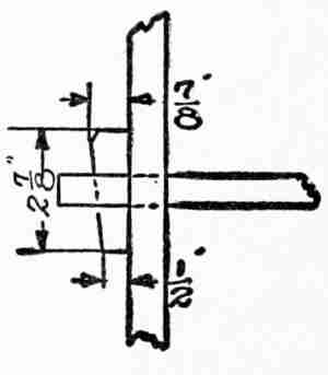
Details of the keys
The parts are now ready to be put together temporarily and squared up in order to fit in the base pieces more perfectly than could be done by mere measurement. It will add a pleasing detail to set back these base pieces 1⁄4 of an inch from the front and back faces.
After all the parts are carefully fitted they should be assembled and the key and screw fastenings inserted. When this is accomplished the bookcase is ready for finishing. As this is a distinct part of furniture making it is reserved for treatment in a later chapter.
A HANGING BOOK RACK
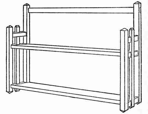
A hanging book rack
The Design.—It is designed to plan a light but strong book rack, to be fastened to the wall of a chamber. Since it is intended to occupy the space that might be given to pictures it is properly as simple in construction as a picture frame, depending upon good proportions and symmetry to give a pleasing effect. The straight lines of the design, which is illustrated above, meet these requirements and also harmonize with the general form and outline of books. Both shelves may be used for books, if desired, but the design permits them to be confined to the lower shelf, reserving the upper one as a suitable place for a bit of pottery or two, or some other choice bit of bric-à-brac. The mortise and tenon joints give the essential stiffness and strength without requiring the use of heavy stock.
Materials and Tools.—Since strength with lightness is an essential feature to realize in the working out of this design, soft woods should be avoided. Ash is probably the strongest of the light woods in common use. Oak is much stronger but heavy and hard to work. White wood is comparatively light and very strong. Gum wood is classified with ash excepting that it is closer grained. Since this book rack is to be used in a chamber in which the wood trim is in enamelled white and most of the furniture of a mahogany finish, it will be equally appropriate to make it of white wood, to be finished in enamelled white, or of bay wood as a basis for mahogany finish. It was decided to adopt the latter course.
The stock requirements for carrying out this design are as follows: 2 back posts, 11⁄4 inch × 11⁄4 inch × 24 inches; 2 front posts, 11⁄4 inch × 11⁄4 × 18 inches; 2 centre uprights, 5⁄8 × 1 × 18 inches; 1 back rail, 5⁄8 × 11⁄4 × 37 inches; 1 end rail, 1 × 11⁄4 × 44 inches; and 2 shelves, 7⁄8 × 7 by 37 inches.
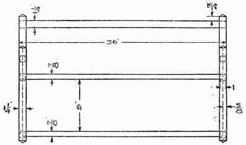
Construction details and dimensions for hanging book rack (front)
The tools needed are much like those required in the previous problem—i. e., the same planes, saws, bitstock, squares, and the gauge; but there will be needed a 3⁄8-inch bit, 3⁄8-inch and 3⁄4-inch chisels, a knife rule, a rabbet plane, a mitre box, and a mallet.
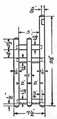
Construction details and dimensions for hanging book rack (end)
Construction.—The details of construction required are as follows: Dressing the stock pieces, cutting the posts to length, cutting the points on the posts, rabbeting the cross rails and cutting them to length, cutting the mortise and tenons, halving on the end rails, cutting and fitting the shelves, cutting, fitting, and fastening the back rail, arranging the clamps and other appliances for gluing up, and cleaning off the glue after hardening.
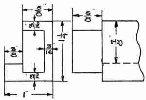
How the tenon is applied to the rail
The stock pieces should be first "dressed" down to the drawing dimensions. This means that they should be planed and sand-papered preparatory to laying out the cutting dimensions. The front and back posts should be cut to length in the mitre box, care being taken to allow an extra 1⁄2 inch for the pointed ends at the top and bottom. These pointed ends are cut in the mitre box by raising one end of the post and sawing to lines squared around the post 1⁄4 inch from the other end. The angle of the cut is made uniform by resting the raised end of the post on a block lightly nailed on the inside of the mitre box, thus giving the same elevation for all the posts. The 1-inch by 11⁄4-inch piece for rails is rabbeted out, using the plane designed for that purpose, and afterward cut to length as called for. The blind mortises should be made not more than 7⁄8 of an inch deep, and the tenons 1⁄16 of an inch shorter in order not to strike the bottom of the mortise. One of these rails should be accurately laid out with knife lines and the rest marked from this as a pattern. The drawing shows the location of the tenon with reference to the part of the rail on which the shelf rests. This is the most convenient position for cutting the tenon and it also gives greater strength. The centre uprights should be halved on after the end rails are in position, being cut for this purpose as illustrated in the drawing. They may be allowed to stand out 1⁄8 of an inch beyond the face of the end rail, and in making the joint an equal amount of stock is to be taken from the rail and from the upright. The shelves are then easily cut to length and the ends fitted with the block plane and dropped into place, being lightly glued and nailed with brads from the under side of the rabbet. Finally the top back rail should be halved in, being left to the last in order that the more important fitting of the shelves may be more easily accomplished.
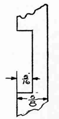
How the centre uprights are halved on
In gluing up the mortise and tenon joints care must be exercised to set clamps out ready for use before the glue is applied so that the parts may be promptly drawn up in position. After gluing they should be allowed to remain about ten hours in order that the glue may properly harden before the clamps are taken off. All the extra glue squeezed out of the joints in clamping must be scraped off with a chisel, after the glue has hardened a little; and any remaining spots of glue must be carefully removed with fine sand-paper so as not to leave anything to interfere with the filling and finishing.
AN UMBRELLA STAND
The Design.—So far as the question of use is concerned, no problem of design could be more definite than this one, since an umbrella rack can have but one use. The only elements of beauty possible are found in simplicity, proportion, and the general effectiveness of the construction for meeting the demands of use. The drawing shows four square, straight posts, squared at the ends, which are allowed to project a little above the top to avoid a box-like effect. All the joints are mortised except the division bars at the top. The cross pieces at the base are made wider not only to conceal the drip pan but to give a more stable appearance to the whole rack.
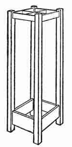
An umbrella stand
Materials and Tools.—Oak is selected as perhaps the most appropriate wood; but other woods, if the surroundings require it, may be used to good advantage. Oak is one of the strongest and most durable of the woods used for furniture and takes well a great variety of finish. It is also quite easily obtained.
The stock requirements are as follows: Four corner posts 11⁄4 × 11⁄4 × 271⁄2 inches; four top rails 1⁄2 × 11⁄4 × 9 inches; four base rails 7⁄8 × 3 × 9 inches; two division bars 1⁄4 × 11⁄4 × 91⁄4 inches; four cleats 1⁄2 × 1⁄2 × 9 inches; and one board 1⁄2 × 71⁄2 × 71⁄2 inches to support the pan.
The same tools in general will be required as in the previous exercises, but it will be necessary to add a 1⁄4-inch bit, a 1⁄4 inch chisel, a steel scraper, and two short clamps.
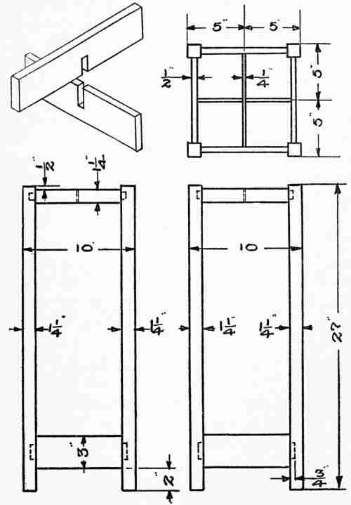
Details and dimensions for umbrella rack
Construction.—All the stock should be planed to size, scraped, and sand-papered with the exception of the base board for the pan, since that is hidden from view. The scraper corrects all slight unevenness of surface and removes scratches and other blemishes. Care should be taken in sand-papering to rub always with the grain of the wood and to avoid rounding the corners. The corner posts should first be cut to proper length and the tops and bottoms slightly chamfered. Mortises are then to be located, bored, and chiselled up. The top and bottom rails should be laid off and the tenons gauged and cut, care being taken not to have them too long. The inside edges of the tenons have to be pared off slightly, as illustrated in the drawing, to allow room for each when they come together.
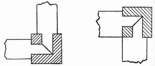
Top rail tenons (left) and Bottom rail tenons(right)
The next step is to assemble the parts, clamp them up, and test them for accuracy. While these parts are in the clamps, measurements should be taken for the cross pieces, which may then be made, allowing extra length of 1⁄4 of an inch in each end for the tenons to enter the top rails. These cross pieces are to be halved together at the centre, as shown in the drawing. The base rails are designed to be thick enough to take up all the space on the inside of the posts so as to hide the corner, as illustrated in the sketch showing the bottom construction.
The next step is to assemble the parts for gluing. It is not necessary to explain this process in detail, since it has already been thoroughly explained in the general section on gluing. It is not necessary to glue on the cleats on which the pan rests; they may be nailed in. When the base is glued together measurements may be taken for the pan.
A MAGAZINE STAND
The Design.—This problem calls for an attractive article of furniture which should also be useful as a receptacle for magazines and current newspapers. An enclosed portion between two of the shelves is desired to conceal from view and preserve for a time the more valuable papers, parts of magazines, or clippings, as may be found convenient. The perspective sketch on this same page shows how these simple requirements are met. The overhanging top adds character and strength to what might otherwise seem too light for the load it is intended to carry.
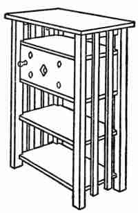
A magazine stand
Materials and Tools.—Oak is selected as a suitable wood because of its strength and durability; for this stand is likely to be in almost constant use. A light wood, delicately finished, would soon show wear.
The stock list, according to the drawing, may be itemized as follows: 4 corner posts 13⁄4 × 13⁄4 × 36 inches; 4 upright slats 5⁄8 × 1 × 34 inches; four shelves 7⁄8 × 101⁄2 × 17 inches; one piece for the top 7⁄8 × 14 × 21 inches; 2 top rails 1 × 13⁄4 × 12 inches; 1 piece for the door 7⁄8 × 8 × 151⁄2 inches for the ends and the back of the closet 1 piece 5⁄8 × 8 × 36 inches; 1 pair 11⁄4-inch brass butts with screws for the hinges, and one brass knob or catch.
The tools needed are a jointer, a block plane, a smoothing plane, steel square, try square, knife gauge, fine cross cut saw, 1⁄2-inch bit and bit stock, key-hole saw, 1⁄2-inch chisel, mallet, nail set, hammer, screw-driver, and steel scraper.
The principal operations are as follows: Planing to size; scraping and sand-papering stock; squaring ends and smoothing them to the required length; laying out gains at corner posts; making mortises for top rails; making the rails; assembling the main parts; fitting ends and sides of the closets; hanging the door and putting on the fixtures.
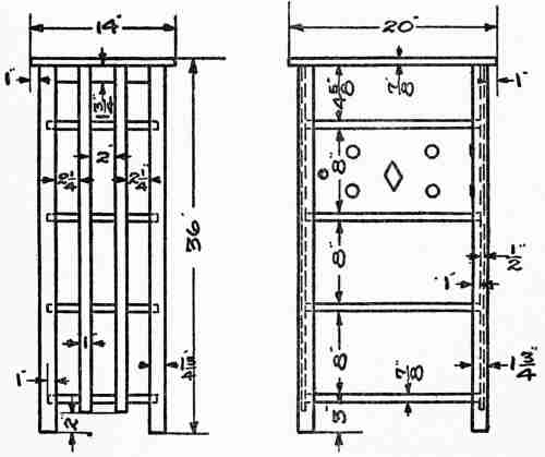
Details and dimensions for magazine stand
The Construction.—Smoothing with the plane and scraping are very important and they should be completed before any sand-papering is done because particles of sand (silica), adhering to the wood, will dull the steel tools. All three operations are needed to remove the marks of the machine tools of the factory, in order to give a good finish in the end. The scraper follows the plane, removing the unevenness which the latter leaves on board surfaces. Sand-papering gives the finishing touches.
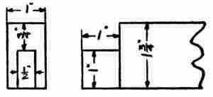
Method of mortising
After the stock is well smoothed, the top and the shelves should be squared off, cut to length, and block planed. The posts should then be cut and accurately trimmed to dimensions. They may be marked with a knife line for the gains into which the corners of the shelves are to be fastened. Since the posts are perfectly square, no attention will have to be given to their exact location in marking or cutting the gains; but when the mortising for the rails is laid out, care must be exercised to mark them so that the mortises will come on the proper faces for assembling. In mortising for the top rail it is well not to work up to the end of the post but to cut back, say 3⁄4 of an inch, as shown in one of the details. The rails may now be laid off and the tenons cut and fitted. It is exactly 81⁄2 inches between the shoulders of the rails. Since the shelves are 101⁄2 inches wide, one inch is thus left on each side to be gained into the posts.
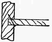
Method of fastening shelf
The parts are now ready for the first assembling. To do this it is convenient to have a clear bench top on which the posts may be laid on one side, face down. The rails and shelves may then be slipped into place, the other two posts placed on top, and the whole clamped firmly together. This is the preliminary assembling for the purpose of testing the accuracy of the work. If it be found all right, it should be taken apart again, and, after glue has been applied to the tenons and to the ends of the shelves, the parts should be quickly re-assembled and clamped up as before, with the angles kept true. Before the glue hardens the shelves should be nailed into the posts, as indicated in the drawing. In this case it is the nail that is the main stay. The glue is accessory, adding much to the stiffness of the construction.
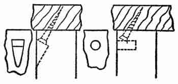
Method of fastening posts to the top
The top may now be set on and fastened by screws or by brads driven through into the posts and well set so that they may be concealed by putty, coloured to match the stain used. The end slats should be fastened on in the same way. The back and ends of the closet are next cut to size and bradded in. The door is then fitted and, to break the surface a little, an ornamental design is cut in the centre. Still further relief is given by setting in the door 1⁄4 of an inch from the edge of the shelf and ends of the closet. The door is now hung on brass hinges, the stop and catch added, and the stand is ready for staining and finishing.
A LIGHT LIBRARY TABLE
The Design.—This is to be a table designed on simple lines and of good proportions. It is to have no drawer but as much shelf room as conveniently possible. The under shelf is designed to be cut out to allow a chair to be drawn up on either side. The end shelves may be regarded as designed to combine a bookcase with the table, thus adding much to its usefulness.
Materials and Tools.—For a table of this kind oak is very appropriate. The following list gives the stock required for one table. The widths and the thickness are as called for in the drawing, but the lengths are given a little long to allow for cutting. A board not less than 9 inches wide and 10 feet long will be needed as stock for the top, the dimensions of which are 7⁄8 × 26 × 39 inches. A 10-inch board, 41⁄2 feet in length, will also be required for the shelves. There will also be needed four legs 13⁄4 × 13⁄4 × 30 inches; eight slats 1⁄2 × 11⁄2 × 18 inches; two back pieces 1⁄2 × 2 × 201⁄2 inches; two rails 7⁄8 × 3 × 32 inches; and two rails 7⁄8 × 3 × 20 inches.
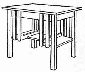
A light library table
The same tools will be required as in the foregoing problems excepting that a 1⁄2-inch bit and a 1⁄2-inch chisel will be required for mortising, and two 3-foot clamps.
Construction.—The first step in the construction is to dress the stock, smoothing, scraping, and sand-papering it, and working the various parts to size. The lengths, however, of all parts excepting the legs are not cut accurately until, in the process of construction, these parts are needed. The legs are at once cut to length and the mortises laid out, bored, and cut. A gain should also be cut in each leg, into which the bottom shelf is to be fitted, glued, and bradded from the under side. The end and side rails may then be laid off for shoulders and tenons, and cut. In this case the tenons should be made 1⁄2 of an inch wide.
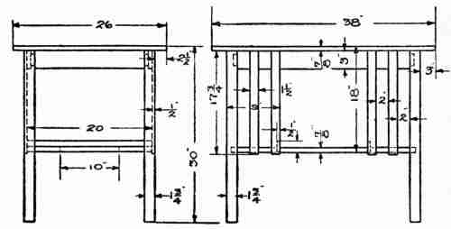
Construction details and dimensions (a) front; (b) end
In gluing up, the top should receive attention first, in order to allow the longest possible time for testing the work under the inevitable changes due to continued seasoning. Great care must always be exercised in making the glued joints. It is often necessary to make them over on account of the development of cracks. Proper care, however, will prevent this. The general directions for gluing, given at the beginning of this chapter, will be of service.
As soon as the top has been glued the four short side pieces may be glued to the shelf, taking pains to make good joints before applying the glue. It should be noted that the inside ends of these short pieces are to be 15 inches apart, and it is important that the ends on opposite sides should be exactly squared across, as indicated in the drawings. This may be accomplished by first locating the centre of the shelf, at the intersection of lines, marked c in the drawing, and measuring 71⁄2 inches each way to the line of the back pieces, which are to run across the whole bottom shelf. As soon as the glue is hardened the ends should be squared and made true to set into the gains when the table is assembled. Finally, the legs, the rails, and the shelf may be assembled, glued, squared up, clamped, and set aside to harden before the clamps are removed.
It is a good plan to brad the shelf in from the under side before the glue hardens. After standing a few hours the table will be ready for the 1⁄2-inch strip which forms the back of the shelf. This is to be fitted and bradded in. Then the slats may be cut to length. They project slightly below the shelf, and are fastened in position by screws. The top may be cut to length and its ends smoothed, after which it may be fastened on the frame by means of screws and buttons, as already described in the early part of this chapter.
A HEAVY LIBRARY TABLE
The Design.—This table, as the illustration shows, is designed to be of simple style, without a drawer or side shelves, and with the bottom shelf keyed into the base rail. Heavy, square legs, and mortise and tenon joints are called for.
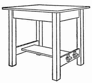
A heavy library table
Materials and Tools.—The mission type of furniture, to which this design belongs, suggests oak as the fitting wood. The stock for the top, the dimensions of which are to be 7⁄8 × 28 × 44 inches, may be cut in three pieces from a 10-inch board, 12 feet long. For the shelf a board 7⁄8 × 12 × 43 inches is required. There are needed also four legs 23⁄4 × 23⁄4 × 30 inches; two side rails 7⁄8 × 4 × 36 inches; two end top-rails 7⁄8 × 4 × 22 inches; two end bottom rails 11⁄2 × 4 × 22 inches; and for keys a strip 1 × 2 × 28 inches.
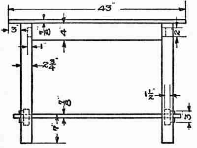
Construction details and dimensions (front)
The same tools are required as were needed in the foregoing problem.
Construction.—Since this table has a larger top than the light library table, even greater pains must be taken than in the case of the smaller table to join the boards for gluing up. All like parts should be laid off together and the necessary mortises and tenons cut and fitted, as in the previous case. The two end rails may be glued into the legs first and clamped, leaving the side rails to be put in place last, when the bottom shelf may also be fastened in without gluing by means of the tenons and keys. The latter should be cut somewhat longer than is really needed so that they may appear to be as effective as they really are; and they should be tapered at least 1⁄2 of an inch in order to drive up well. A small brad may be driven in to keep them from getting loose when the work shrinks.
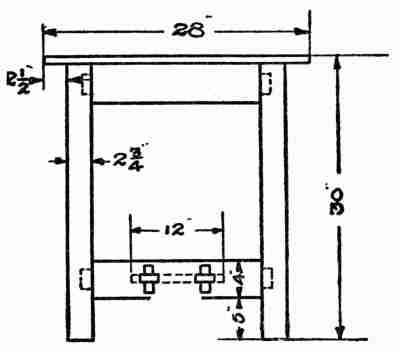
Construction details and dimensions (end)
A BOOKCASE WITH GLAZED DOORS
The Design.—This is to be an upright bookcase, with five shelves and an overhanging top. Some variety of surface is afforded by the arrangement of the sash, as indicated in the drawing. The shelves are made to be adjustable, and not fixed as in other problems.
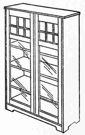
Bookcase with glazed doors
Materials and Tools.—The stock required for one bookcase of this pattern is as follows: two end pieces 7⁄8 × 111⁄2 × 481⁄2 inches; for the top and bottom, two pieces 7⁄8 × 12 × 40 inches; four shelves 7⁄8 × 11 × 40 inches; for the sides of the doors, four pieces 7⁄8 × 2 × 45 inches; for the top and bottom rails of the doors, four pieces 7⁄8 × 21⁄2 × 18 inches; for the middle rail, one piece 7⁄8 × 2 × 18 inches; for the sash, one piece 7⁄8 × 1⁄2 inch × 6 feet; for the back, enough 1⁄2 inch stock to cover the space 38 × 46 inches. In addition to this there will be required four hinges, two catches, a lock, and glass for the sash as dimensioned in the drawing. It is not necessary, however, to cut the small lights. One large pane of glass may be set in the full width of the door so that the small sash divisions may be apparent rather than real.
The tools for this problem are the same as those used in previous problems with the addition of a 1⁄4-inch bit and 1⁄4-inch chisel, and a rabbet plane, or a universal plane for cutting out the rabbet for the glass.
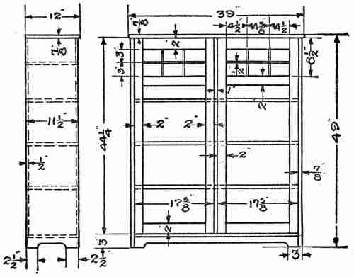
Details and dimensions for bookcase
It is not necessary to give directions for the treatment of the stock, since it is practically the same as that employed in preceding problems. The details for cutting dimensions are given in the accompanying drawings. It would be well for the young woodworker to study these carefully and make out a working plan of procedure similar to that which has been outlined in other problems.
Construction.—The first thing to do is to erect the bookcase—i. e., to cut the sides, the top, the bottom, and the back pieces to proper form and dimensions, bring them into position, and fasten them. It will be noticed that the sides and top are rabbeted out, as indicated in one of the small drawings, so that the edge of the back will not show when it is nailed in position. The bottom shelf is also made narrow enough to allow the back boards to be brought down over it and nailed to the edge.
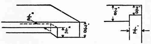
Method of concealing ends of back boards
After the case is erected the doors should be laid out according to the drawing for mortises and tenons, and the inside edges rabbeted to give an inset for the glass. If it is decided to use one large light at the top of the door instead of six small ones, the sash effect for this light will have to be made of pieces thin enough to allow this arrangement. When the doors are ready for setting the glass it may be held in place by small 1⁄4 round strips, bradded in behind it. Great care should, of course, be exercised in gluing up the doors to avoid strains which might give them such a twist that they could not be fitted to the case. Careful fitting of all the mortises and tenons and the usual assembling of the parts of each door before gluing is attempted is a wise precaution. It will also be wise to allow a little stock for trimming off, both on the sides and on the ends, when the doors are finally fitted in.
A ROUND CENTRE TABLE
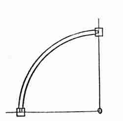
Details and dimensions for round centre table
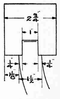
Detail of top mortise
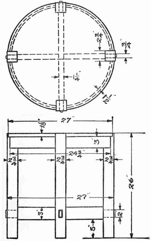
Details and dimensions for round centre table
The Design.—This problem calls for a table of mission style with square legs set into the circumference of the table flush with the top and having tenons exposed on the face of the legs. Simplicity of form combined with strength characterizes the design.
Materials and Tools.—Quartered oak is recommended for a table of this design. The stock required for one table is as follows: four legs 23⁄4 × 23⁄4 × 27 inches; two cross rails 11⁄4 × 3 × 29 inches; one piece of 3 × 12 × 20 inches for the curved rails; and stock enough to make a round top 11⁄8 inches thick and 27 inches in diameter.
The only tools desirable to provide, in addition to those previously used, are a trammel and spokeshave or a circle plane.
Construction.—The first step is to join up and glue the top so that it may have ample time to harden and dry while the other work is being accomplished. The stock for the legs may then be dressed and the bottom mortises marked and cut through the posts. Care must be taken to transfer the marks to the opposite side so that the mortises may be accurately outlined on the face. Care must also be taken in cutting the mortises, in order to make good, clean joints. A dimensioned detail of the top mortises, which are to receive the tenons of the curved rail, shown on page 180, should be consulted before laying out this work. It should be noticed that the legs project 11⁄4 inches above the top rail. After the top mortises are cut the cross bottom rails should be halved together and the tenons laid off and cut. It will be noticed that the projecting end of the tenons is to be bevelled off, but this should not be done until the fitting is completed.
In laying out the plan of work for the construction of the curved rails the trammel comes into use. With this, mark off carefully the inside and outside curves on a thin piece of board and, with a large steel square, draw straight lines from the centre or pivot point, making an exact quarter circle. This is shown in one of the drawings on page 180. Then, parallel with each straight line and on the inside, mark off other lines one half the thickness of the leg. This locates the shoulder of the tenon. The pattern should then be carefully cut out of the thin board and used as a template for marking out on the stock the form of the curved rails. After these rails are band sawed and smoothed, the tenons may be cut.
When the framing parts of the table have all been cut and fitted they may be assembled and glued. Finally the top is placed face down on a bench top or on horses, and the inverted frame laid over it and centred to give the correct position of the insets for the legs. These should be laid off with great care, the outline reproduced exactly on the opposite side, and the stock cut out. The top and frame should then be fastened together from the under side. After a few finishing touches have been given to the projecting ends and exposed surfaces, the table will be ready for the filling and varnishing.
A LIBRARY DESK
This is the most ambitious of the special problems in furniture making here suggested. Details are given in the drawings on the opposite page. If the young woodworker can give sufficient time to it and can command the services of a few machine tools it will not be an unreasonable task to undertake. Most of the operations required in its construction have already been carefully explained and need not be repeated as detailed directions. There are, however, one or two principles of cabinet-making called for in this problem which were not required in the others. They will therefore need explanation.
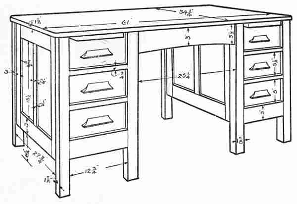
A library desk
Panelling.—To avoid the difficulties which would result from the swelling, shrinking, and warping of wide surfaces in furniture it is common practice to make use of the panel. The design of the panel is easily understood. It consists of a framework of ordinary thickness, put together usually with mortise and tenon joints. The inside edges of this framework are grooved, and into the groove is fitted a piece of stock generally thinner than the frame which fills the space between the sides of the frame. The panel board may be in one piece of wide stock or it may be glued up. It may be of very thin stock inset on both sides of the panel, or it may be of thicker stock inset only on one side, and perhaps not inset on either side, in which case only the edges of the board are made thin enough to run in the groove of the panel frame. In this problem the panel board is to be made of 1⁄2-inch stock, flat on the outside, and inset 1⁄4 of an inch. The back of the panel board is flush with the frame and is chamfered off to give the necessary tongue all around to run in the groove. The narrow stock of the framework is not likely to swell or shrink appreciably and, if well constructed, cannot become warped or twisted. The panel, on account of its greater width, may and generally does swell and shrink considerably; but it should be fitted to move easily in the grooves so that its changes may not be noticeable. Should it be desired to finish the panels with a moulding this should be nailed to the rails, not to the panel board.
Danger in the Power Saw.—The panel frame may be constructed by hand, but if a circular saw be available it will be found of great service. Beginners, however, should employ the services of an expert sawyer and not assume the great risk involved in the use of a circular saw or even a band saw, especially if these saws are without guards. The necessary operations should be carefully laid out on the partially finished stock, with a good square and gauge. A combination plane is quite essential for cutting the grooves; and this carries its own gauge. Care should be taken to make all measurements from the centre of the piece, and gauge and square always from the face sides and from the face edges of the joints. The cuts that it is necessary to make for the joints are indicated in the drawing. In gluing up, the directions already given in the section on gluing should be followed.
Sand-papering.—There is a legitimate use for sand-paper in the finishing stages of the work on this desk, as there is, in fact, in almost every kind of fine woodwork. Its use has already been advised in the directions for furniture making. In furniture manufactories sand-papering machines are among the most expensive machines to be found in the shops; and their high cost is of course justified by their productive value. It is quite impossible to work down large pieces to a good surface by the process of planing. If a sand-papering machine is within easy reach of the amateur cabinet-maker, it will be very desirable for him to send all large pieces like the tops of tables and panel boards to the factory in order to have them run through the machine. The expense is very slight. In sand-papering by hand considerable pressure should be applied as evenly as possible and always along the grain. Any movements directly across the grain or at an angle are sure to show through the finish. The process is facilitated by wrapping the sand-paper around a block of wood about 2 × 4 inches in diameter or, better still, a block of cork of the same dimensions.
A MORRIS CHAIR
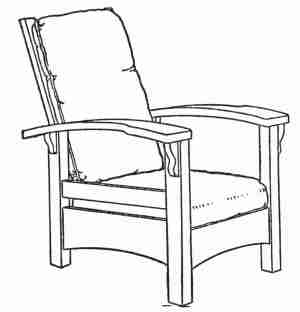
A Morris chair
History of the Design.—Among furniture designs the Morris chair has become a classic. It takes its name for its originator, William Morris, the great English designer and reformer, to whom, perhaps more than to any other person, we are indebted for sane and honest work in furniture design and in all forms of household decoration, not only in England but in other European countries and in America. And probably no one of his creations has done more to teach the lesson of simplicity, comfort, and utility in furniture than the Morris chair.
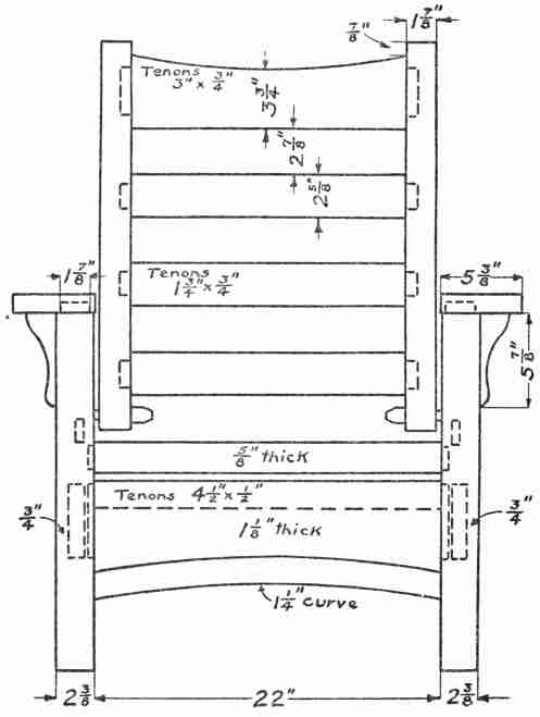
Details and dimensions of Morris chair (front)
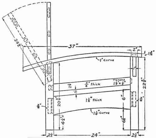
Details and dimensions for Morris chair (side)
It may be well to add, however, that like many other famous works of art, the original design of William Morris has suffered much in countless imitations. The furniture shops display carved and otherwise embellished monstrosities under the name of Morris chairs which are nothing less than an insult to the great name they bear. But the life of all imitations of original and really great ideas is bound to be short. Only the good and true, which are the original, survive. The really valuable features of the original Morris chair design, combining beauty of material with simplicity of form and construction, have taken a lasting hold upon the hearts of all people who have found solid comfort in these chairs. The chairs contemplated in this problem are illustrated on page 50, chapter II. Both are in quartered oak. The one on the right is stained in dark brown and has a box cushion for the seat and a pillow cushion for the back, in medium brown leather. The one on the left is in light fumed oak with cushions of mahogany velour. On account of its smaller dimensions it is somewhat lighter in weight than the one on the right, and the dimensions of the smaller one will be followed in this problem. This chair is an exact copy of one in ash which, with a centre table and stool, were designed and made for a college girl's room; and a large part of the work of constructing the three pieces of furniture was done by the girl herself.
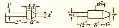
Detail of pins
By careful examination of the dimensioned drawing shown on the preceding page the young woodworker who undertakes this problem should select his stock according to the following list: 4 legs 21⁄2 × 21⁄2 × 24 inches; two arms 3 × 51⁄2 × 38 inches; two bottom side rails 11⁄8 × 6 × 26 inches; two top side rails 5⁄8 × 21⁄4 × 26 inches; two bottom rails (front and back) 11⁄8 × 6 × 24 inches; one top rail (back) 5⁄8 × 21⁄4 × 24 inches; two back uprights 11⁄8 × 17⁄8 × 25 inches; three cross pieces for back (lower) 3⁄4 × 25⁄8 × 20 inches; one cross piece for back (top) 3⁄4 × 6 × 20 inches; one bracket 1 × 3 × 18 inches; four pins 41⁄2 × 41⁄4 inches square.
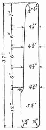
Detail of Morris chair arm
In sawing up the stock, allowance should be made of course, for necessary waste in working down to the drawing dimensions. The arms are drawn with a curve and may be fashioned by band sawing them out of 3-inch stock. There will be a considerable saving in material and labour, of course, if the arms are made flat; but the effect of the curve is very pleasing. The back slats may be sawed to a slight curve, which is another attractive feature; but flat slats are easier to make and just as serviceable.
The process of construction does not differ in general from that already described in some of the foregoing problems, and need not be repeated here in detail. The method of finishing this and all other furniture referred to in the problems will be explained in the following chapter.
Since the Morris chair is a heavy piece of furniture, it will be necessary to provide casters for it. The Acme Pin caster, so-called, was used in the chair referred to in this problem. It makes use of a steel ball turning upon ball bearings, and is set up into the legs so as to leave only about 1⁄4 of an inch of the ball exposed.
A HALL CLOCK
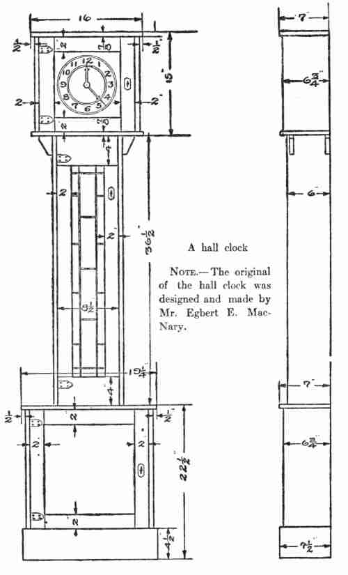
A hall clock
Note.—The original of the hall clock was designed and made by Mr. Egbert E. MacNary.
Design.—This clock was designed and built to conform to the requirements of the space allotted to it. The lines of the case are all straight; there are no spires or gables or fantastic curves on the top. A hall clock is indoors, and the top should be horizontal; for all the other lines such as tops of window casings, picture moulding, etc., are horizontal. If the clock stood out of doors under the stars, then the top might be spired or pointed.
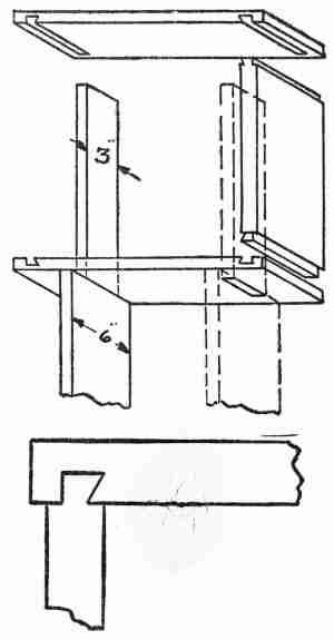
Construction detail of a hall clock
The construction, as indicated in the sketches, is simple and substantial. The long sides extend the entire height of the clock, being firmly joined into the base and head. The works are supported between these sides. The wood is 3⁄4-inch quartered oak, hand dressed, and stained a warm brown. The dial, hinges, catches, pendulum, and weight are of brass.
Cutting Glass with a Wheel Cutter.—The long door has a panel of transparent leaded glass. This leaded glass work is a most fascinating process. The lead strips required for it were purchased of a dealer in lead specialties. Stained glass window concerns are usually willing to sell this lead. A full-size drawing was made of the design for the glass panel and the glass cut in pieces to match the pattern. A ten-cent wheel glass cutter was used. One caution, kept in mind, will enable one to use a wheel cutter of this kind without injuring it. It should never be used twice in the same cut. One stroke of a few inches over a cut previously made will ruin the wheel; but if the wheel is not abused by tracing over a cut, it will last a long time. The glass should be laid on a level table and the cutter used with a firm hand, making a continuous cut against a straight edge.
Soldering.—The long lines of the design are in one piece; and there is a strip around the entire outside edge. To solder the pieces together, the glass and lead strips are laid in position on a board, and brads (about 1 inch long) are driven part way into the board close against the outside strips, so as to hold the pieces in position. A small bead of soldering paste is placed on each joint. A small soldering "iron" (which is really copper) and wire solder are used. The copper may be "tinned" by filing the point bright, heating it, dipping it in the soldering paste, and then quickly touching it to the solder wire. The point will become coated with the solder, or, as we say, "tinned." The iron will need frequent heating. A quick, light touch of the iron and solder wire to the joints will give the best result.
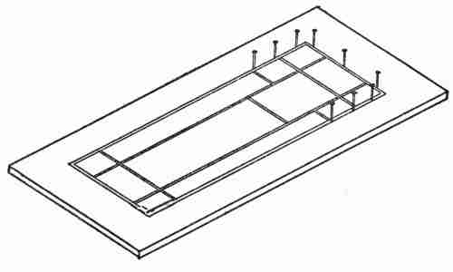
Method of holding glass and lead strips for soldering
The two rings in the brass dial were "raised" by driving the brass into a groove in a piece of oak with a hard wood wedge. The piece of oak was revolved around the dial by means of a nail driven through the centre of the dial into the oak piece. When a short arc of the ring had been raised, the grooved piece was swung around about 1 inch and the groove continued.
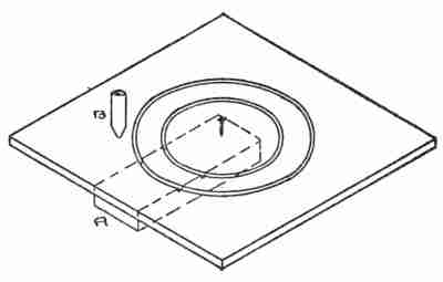
Method of raising the dial rings
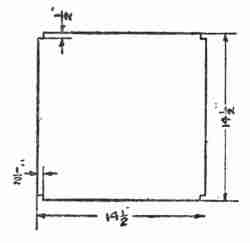
Dimensioned dial piece of clock before edges are turned
The length of the pendulum depends upon the number of teeth in the escape wheel. It was necessary in the case of this clock to take out the escape wheel, which had 32 teeth, and substitute one of 22 teeth to accommodate the length of pendulum desired.
OUTDOOR FURNITURE
The greatest charm of home life in the summer season is rarely found within the house. This is especially true in the village or in the country, where nature is at her best; but even in city homes that are fortunate enough to include in their surroundings a small yard, a bit of garden, or any means of connecting the home with "God's great out-of-doors," though it be but a sheltered balcony or a window garden, the touch of nature is not lost. It is possible, however, for art to assist nature; and in many cases her assistance is very much needed. It is certainly true that nature cannot be left wholly to herself in the neighbourhood of the village or city home. If there be a garden, as much forethought must be exercised in planning it and as much pains taken in developing and caring for it as is called for in working out any form of interior decoration. There are problems of design and construction suggested by the need of suitable chairs and settles for the piazza, comfortable hammocks and couches for the balcony, awnings for the windows on the sunny side, and the right furniture, perhaps, for an out-door dining-room. The more decorative features are found in the rose arbours, the trellises, the garden screens, the lawn tent, the pergola, and the garden gate; and all these offer problems that easily come within the reach of enterprising and capable young craftsmen.
General Types.—In the designing of out-door furniture there are two suggestions from nature that may appropriately find expression. On the one hand large masses, as seen in the hills and rocks, suggest solidity, weight, and permanence. This idea is embodied in walls of masonry, stone posts, iron gates, stone or concrete pedestals, or in some other kind of heavy construction. On the other hand, there are the suggestions of lightness, delicacy, and growth, seen in the growing vines, shrubbery, and small trees, which are carried out in the so-called rustic furniture, trellises, arbours, and garden screens.
An Example of Heavy Furniture in Wood.—A settle designed for comparatively permanent use in some cool or retired corner of the garden may be made of native pine, white wood, or spruce, well protected by several coats of paint. A suggestion is here given for such a design, laid out on substantial lines. Ordinary 4 × 4 spruce, planed, may be used for the posts, pine or white wood for the rest of the construction, 2-inch stock being used for the back pieces and arms, and 7⁄8-inch boards for the rails and seat. Mortise and tenon joints should be used in the framing. The illustration shows also a simple design cut in the back pieces and repeated in the two front posts. It is a decorative feature which seems to counteract, somewhat successfully, the general severity of the lines on which the settle is designed to be built.
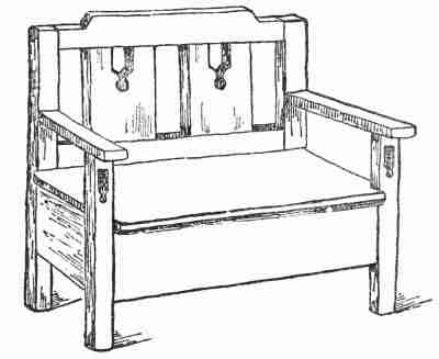
A garden settle
Concrete Furniture.—Still more substantial out-door furniture may be made of concrete cement. This material has come into use for sidewalks and pavements and as a substitute for brick and stone masonry in retaining walls, bridge abutments, and in a great variety of heavy building construction. Concrete is, in fact, an artificial stone, made by mixing Portland cement with sand or pulverized rock in the right proportions, thoroughly wetting the mixture with water, and allowing it to harden. It is so commonly associated with heavy, crude work that it is not easy to believe that it may be also fashioned into anything of an artistic or decorative character; and yet it is capable of a wide range of out-door decorative uses. Gate posts, pedestals, fountains, window boxes, urns, and other forms of garden pottery in great variety, tables, and garden seats, have been successfully moulded in this material. Its natural stone gray colour and surface are well suited to many of these uses; but it may be given a variety of colour effects in bold design if occasion requires it. In weight and durability it leaves nothing to be desired.
The Wire Form.—Concrete cement cannot be modelled like clay. In its formative state it is too soft for such manipulation. It must be supported in some way while it is being worked into the desired shape and until it has hardened. In general there are two methods of giving the necessary support: viz., by employing an interior framework or skeleton, generally of wire lath, which is permanently encased in the cement; or by using a plaster or wooden mould into which the material in a soft and plastic state is poured and from which it is removed when hardened. The latter method has been elaborated quite extensively for commercial purposes, because it readily yields an indefinite number of marketable results from the same moulds. The simpler wooden moulds may be easily made by a clever boy; and after a little experience he can soon learn how to mix the cement properly and mould a form successfully. For single pieces of concrete work, however, the wire forms are to be preferred. A suggestive illustration of this method is found in the following problem:
A CYLINDRICAL GARDEN VASE
The dimensions called for in this design are a diameter of 10 inches and a height of 8 inches. The wire form must therefore be made to approximate quite closely to these dimensions. A good material for the form is galvanized wire lath of 1⁄2-inch mesh. This problem will require a piece about 8 inches wide and 34 inches long for the convex side, and a piece about 10 inches square for the base. From the square piece a circle 10 inches in diameter should be cut out. A strong pair of tinners' shears will be needed for this purpose. In bending the long piece into the cylindrical form it is well to proceed slowly in order to produce an evenly curved surface—i. e., one free from angular bends. A good way to accomplish this result is to lay the piece down on a bench top and bend it up over a cylindrical wooden block. If nothing better is available a rolling pin will serve this purpose. When the bending is nearly complete, the two ends of the piece should be brought together, lapped over about an inch, and bound together with free ends of the strands of wire. A pair of pliers will be of great assistance. If this part of the process has been carefully done, there will result a cylindrical form 10 inches in diameter. The circular piece should now be attached to one end of this form by means of the free ends of the strands found there, bending the projecting wires over and clinching them at convenient points on the circumference of the circular piece where there are uncut meshes of the wire. The form is now ready for covering with the cement.
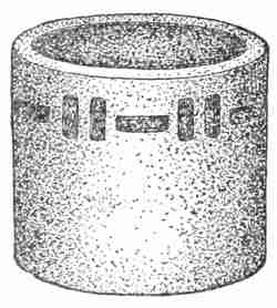
A garden vase
The first step is the mixing of the cement for what is known as the scratch coat. This is made by mixing Portland cement with fine, clean sand in the proportion of one part cement to two of sand. These ingredients should be thoroughly mixed together in the dry state, and then there should be added a small quantity of goats' hair, well picked apart. For the problem at hand about five pounds of cement will be needed and as much goats' hair as can be held in the hand. The whole should be thoroughly wet down with just the right amount of water. It is important that the mixture should not be made too soft. A scratch coat should be given a consistency that will enable it to be easily spread over the wire form and, at the same time, to hang well together.
When a sufficient amount of the right mixture has been obtained, it should be spread upon the wire form by means of a small mason's trowel or a large knife. It is well to begin at the bottom of the convex side of the cylinder, working upward, taking no pains to make this first coat smooth, since roughness is desirable, and paying no attention whatever to the inside of the cylinder, excepting to see that the cement is forced well through the meshes so that the whole mass will be held together firmly when dry. The inside is given a smooth coat as a part of the later finishing process. When the convex surface has been well covered, the form should be turned bottom up and the cement spread upon the base of the cylinder in the same way. After the wire has been completely covered, the form, which is likely to be somewhat distorted, should be corrected by careful manipulation till a true cylinder has been obtained. This is allowed to stand for about five hours until the cement has thoroughly hardened. It is then ready for the finishing coat.
The next step in the process is to make the cement for the finishing coat. Considerable variety is possible here, depending upon the colour and other surface effects that are desired. In this design a light, sparkling surface when finished is required. To produce this effect a mixture of one part Portland cement and two parts marble dust will be needed. This should be mixed without hair to a consistency like that used for the scratch coat.
Before applying the finishing coat the surfaces should be thoroughly moistened by means of a brush well filled with water. There are various methods of applying this coat. The simplest is carefully spreading it on with a trowel and smoothing it with the moistened hand. When the surface has hardened sufficiently it is sometimes possible to improve the finish by the judicious use of sand-paper or a coarse file. It is not possible to produce perfectly even surfaces in this way; and yet the method has the characteristic freedom of handwork in general, and yields very satisfactory results.
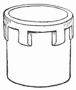
A vase with blocked rim
The Decoration.—A great variety of decorative effects may be obtained in concrete pottery and in other articles made of this material for out-door use. In pottery these decorations may take the form of raised figures or ornaments, of borders or designs cut in the surface, and of inlays in colour. Whatever the form of design, the necessary cutting for it is best made when the cement has become well set but not very hard—i. e., from 6 to 10 hours after the finishing coat is applied. A stout, sharp, pointed knife blade is all the tool that will be required. A narrow chisel, however, may be found desirable for deepening the cuts. The knife should be guided by means of a ruler, which should be flexible if used on curved surfaces; and the depth of the cut will depend somewhat upon the size of the piece. In work similar to that described in the problem just given, a depth of 3⁄16 or 1⁄4 of an inch is sufficient. This cutting, of course can be made after the cement has hardened, by the use of hammer and chisel; but it will be much more difficult.
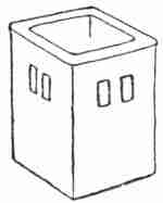
A square form
The Colours.—Colour cement for inlaid designs is made by using the best quality of white Portland cement as a base, colouring it with dry mineral pigments which are sold by dealers under the name of lime or cement-proof colours. Among the pigments suitable for this purpose are red oxide of iron, which produces a red; oxide of cobalt, which gives a good blue; chromate of lead, which produces yellow; carbonate of copper, which gives a good dark green; and burnt umber, which yields a good brown. These come as dry powders and should be mixed with the dry cement and marble dust, making a mixture of uniform colour, before the water is applied. In order to determine the right colour it is well to experiment with a small quantity of the various ingredients until a satisfactory shade has been found. Then with this as a guide a sufficiently large quantity should be mixed, in the same proportions, to the consistency of a thick paste, and applied to the design, which has been previously cut in the surface to be decorated. To insure thorough adhesion of the paste to the concrete, the cutting should be well moistened with a wet brush. A number of suggestive designs are shown in the accompanying drawings.
Rustic Furniture.—The lighter out-door furniture can be easily made up in a great variety of designs. The form of rustic settles and chairs is determined largely by the material which is available. Very useful and ornamental effects are produced by using sticks cut from the tops or from branches of small trees. Birch saplings, easily found in the second growth of some wood lots, afford a good supply of material. It is not necessary that the sticks be straight; the natural crooks and notches are often very useful in bracing the framework. Chairs, settles, tables, standards for flower boxes, and other articles of furniture may be made out of this rough and unfinished material.
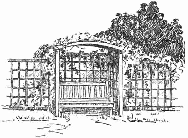
A garden screen
Lattice Work.—Trellises and garden screens have been made in an almost endless variety of forms. Among the most satisfactory is the plain lattice work in squares and rectangles. Its simplicity and evident durability are points in its favour. Experience proves also that vines and other plants needing support are readily adjusted to this form of trellis. The size of the stock required in making the right-angled lattice work depends upon the uses to be made of it. For a garden screen the uprights need to be of 2 × 2 inch stock and of any convenient length. End posts of 3 × 3 inch stock will be required, to give necessary stiffness; and, if the screen be a long one, intermediate posts of the same size should be placed at intervals of ten or twelve feet. The horizontal pieces may be strips of 7⁄8-inch stock, 2 inches wide, set their full thickness into the uprights. Spruce furring, which lumber dealers supply in 2-inch widths, is suitable for the small rails; but if chestnut be used for the uprights it is well to use the same wood for the rest of the construction. The top and bottom rails should be of heavier stock, not less than 2 by 3 inches. The best foundation is a line of concrete posts, firmly set into the ground at intervals of 6 feet, to which the bottom rail or the uprights are fastened by means of irons set into the cement when the posts are formed. Two coats of dull green paint will protect the wood and properly subordinate the lattice work to the trailing branches which it supports.