PART I. SECTIONS 1-106.
Reading edition
(For Additions see pages 245-335.)
Section 1.—ANCHORING.
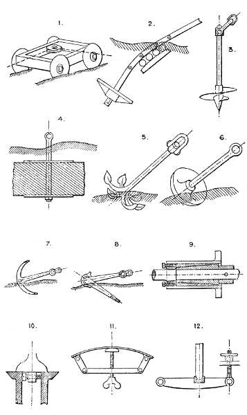
1. Rope pulley anchor—a car which grips by sinking its wheels in the soil; employed for ploughing tackle.
2. Anchor plate—buried in the ground below a mass of masonry—for attaching guys, tie rods, &c. Sometimes a frame, or plate, laid on the ground and ballasted, is the method used.
3. Screw mooring, screwed into the ground.
4. Heavy stone sunk in the ground and having a ring attached; or a mass of concrete, similarly placed, used for guy ropes, tie rods, and foundation bolt attachments.
5. Grapnel.
6. Mushroom anchor.
7. Double fluke anchor.
8. Martin’s patent anchor, with swivelling flukes. Several other patent anchors are modifications of this.
Stakes, with or without flanges, vertical or horizontal, are sometimes employed, the flanges taking the cross strain of the ties, &c. Fencing posts, gate posts, tree stakes, and tennis poles are of this class.
Section 2.—ADJUSTING DEVICES.
For adjustment by Screws, see Section 78, and by Wedges, see Section 36, These are the commonest appliances employed. For Cams also, see Section 9. For adjusting Pedestal Brasses, see Section 46.
For adjustments by keys, cotters, &c., see Section 37. See also Nos. 251, 269, and 297.
9. Split cone sleeves and set screw adjustment for a revolving standard, or similar detail, where there is much wear or great accuracy is required in the revolving bearing.
10. Centre-line adjustment for lathe headstocks, &c.
11. Variable curve adjustment; used in compass planes, instruments for drawing arcs of circles, &c.
12. Vertical shaft footstep adjustment; employed on millstones, horizontal grinding mills, &c., to regulate the space between the grinding surfaces. See No. 261.
Larger plate.
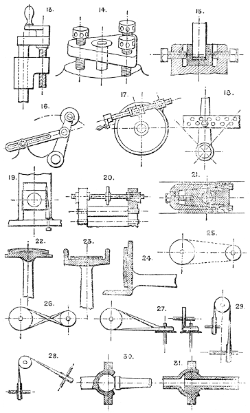
13. Side screw adjustment for injectors, jet pumps, &c.
14. Levelling adjustment; can be used with either 3 or 4 screws: for telescope and level stands, theodolites, &c.
15. Horizontal central adjustment for footsteps, &c.
16. Slotted link and lock nut for adjusting angle of a lever.
17. Disc and ring with partial angular adjustment by a screw and nut; used for screwing dies, self-centering chucks, &c. The nut and bearing of the screw have allowance for swivelling.
18. Pin and hole adjustment for a lever or similar detail.
19. Wedge bearing for locomotive horn plate guides, slide bars, and similar parts subject to wear.
20. Right and left-hand screw and wedge adjustment for roller bearings, &c.
21. Adjustment for wear used on engine crossheads to take up the wear of the working faces.
Adjustable Crane Balance Weights, Section 18.
Adjustable V-guides, Nos. 700 and 704.
Section 3.—BELT GEARING.
Materials employed are:—Leather, cotton, guttapercha, indiarubber, canvas, camel-hair, catgut, flat wire or hemp rope, steel bands, flat chains, &c.
22. Ordinary belt pulley, “crowned” on face to retain the belt on the centre of the pulley.
23. Double-flanged pulley, flat on face, sometimes “crowned,” as No. 22.
24. Single-flanged pulley for horizontal driving.
25. Open belt gear; runs best as shown, with the slack half of the belt at top.
26. Crossed belt to reverse motion on the driven shaft. Also to obtain more grip for the belt than with open belts.
27. Mode of driving when the shafts are at right angles to one another.
28. Mode of driving with shafts at an obtuse angle, sometimes used instead of bevel wheels.
29. Arrangement adopted when the pulleys cannot be got in line with one another, or the shafts are too close together to drive well direct. Short belts seldom work well.
Belts are frequently arranged to pass under and over several pulleys so as to drive several shafts by one belt.
For reversing by belt gear, see Section 74. Gut bands (round) are worked over V-grooved pulleys; see Rope Gearing, Section 66. Belts may be kept tight by tightening pulleys, see No. 1207. For round belts, see Rope Gearing, Section 66. V-belts are occasionally used, formed of thicknesses of leather riveted together, cut to a V-section, and worked over V-grooved pulleys.
Section 4.—BALL-AND-SOCKET JOINTS.
30. Universal hinge. The arm can be fixed in any required position by tightening the gland. Useful for stands for articles to be exhibited in any position, telescopes, &c.
31. Pipe joint, with similar capabilities.
Larger plate.
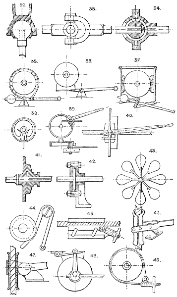
32. Same as No. 16, but with screwed gland. If used without the arm, it forms the ordinary ball castor.
33 & 34. Dr. Hooke’s universal joint. See application, No. 292. See also Nos. 1359 and 732.
Gas pendants are suspended with a joint similar to No. 31, but the ball, having only a restricted angular motion, is cut down to a segment only.
Section 5.—BRAKES AND RETARDING APPLIANCES.
To retard or arrest motion (revolving or rectilinear).
35. Strap and lever brake. The strap is usually faced with wood or leather, but sometimes is used without either. Wood is liable to become noisy. Leather gives the best grip. Iron upon iron, or wood upon iron is not safe if liable to become oily or wet.
36. Block and lever brake. Wood or cast-iron blocks are used.
37. Compound block and lever brake; avoids putting cross strain on the shaft—used on winding engines, &c.
38. Internal toggle brake, employed for friction clutches. See Section 15. The inner ring is turned to fit loosely inside the outer ring and split, the toggles being arranged as shown to expand the ring till it is locked to the outer ring.
39 & 40. Double block and lever brake on wheel rim grips the wheel rim between the lever stocks or jaws. The strains are self-contained.
41. Disc brake; considerable end pressure is required with this form, and must be arranged for in the bearings of the shaft.
42. Compound disc brake. Several discs may be employed, sliding on feathers on the shaft.
43. Fan brake; may be run openly in air, or enclosed in a drum with water, oil, or other liquid. (See Allen’s patent Governor, &c.)
44. Spring brake, acting on a small grooved pulley; for light purposes.
45. Rope brake or grip, with toggle motion, and screw for relieving.
46. Rope brake: grips by the angular distance between the jaw centres becoming less as the lever end falls.
47. Rope brake; with cam lever gripping motion.
48. Eccentric action lever and block brake. The eccentric is fixed to the brake lever. This plan also avoids cross strain on the shaft.
49. Strap and screw brake.
Larger plate.
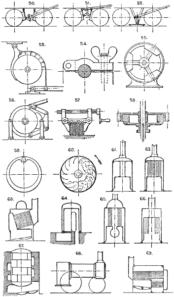
50, 51, & 52. Three forms of car brakes. See also the common “skid” or cart brake.
53. Combined strap and lever brake. (Fielden’s.)
54. Shaft grip, or brake.
55. Centrifugal brake, or clutch. The weight segments are driven into contact with the ring by centrifugal force. Springs may be used to return them out of action.
56. Three-segment compound brake: grips the wheel all round.
57. Compound bar brake, with right and left hand screw grip levers, used for heavy gun compressors.
58. Compound ring brake, on similar principle to No. 57. See remarks to No. 41.
59. Wedge and split ring, used for internal brake ring or clutch, in a similar way to No. 38.
60. Hollow drums, with radial pockets, half filled with loose material, or water, mercury, &c., which retard the motion of the drum by the weight and friction of the loose material.
An hydraulic cylinder and piston is frequently used as a brake or retarding device for reciprocating motion, the water passing from one side of the piston to the other, through an adjustable valve. Friction brakes are employed as dynamometers to indicate the power given off or absorbed by any piece of machinery. Automatic brakes (see Sections 15 and 69) are used for hoisting machinery, &c.
Brushes, formed of stiff bristles or wire, are used as a retarding device for circular or rectilinear motion.
Section 6.—TYPES OF BOILERS.
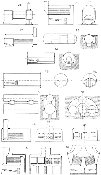
Vessels or containers of every conceivable shape have been used as boilers. Many of the older types are now obsolete, but the following are these most commonly used:—
VERTICAL BOILERS.
61. Ordinary centre flue boiler. Sometimes the centre flue is surrounded with tubes, as No. 65.
62. Vertical multitubular.
63. Vertical boiler, with diagonal tubes and smoke boxes.
64. Vertical return-flue.
65. “Pot” boiler.
66. “Field” boiler; with suspended tubes and internal circulating tubes.
67. Vertical egg-end boiler; with spiral flue. Large vertical boilers sometimes have cross flues, or large tubes.
HORIZONTAL BOILERS.
68. Portable “loco-type” multitubular.
69. Fixed return-tube.
Larger plate.
70. Fixed “loco-type” multitubular; a favorite and useful form, giving good results, and easily cleaned.
71. Fixed “loco-type,” with underneath fire-box; sometimes used to economise space, is self-contained, and usually stands on cast-iron feet.
72. Multitubular-horizontal; self contained; on cast-iron feet.
73. Egg-end boiler; not much used except where the coal burnt per h.p. per hour is not an important consideration.
74. “Cornish”; one flue, with enlarged fire-box tube. This type is often made with a parallel flue with cross tubes fixed at intervals throughout its length.
75. “Lancashire”; two flues; sometimes has enlarged fire-box tubes, as No. 74.
76. Oval flue boiler, with “Galloway” tubes. The Lancashire type is frequently combined with this form by arranging the two circular flues to open into one oval one.
77 & 78. “Elephant” boilers; employed in connection with coke ovens and other sources of waste heat.
MARINE BOILERS.
79. Ordinary box form, with internal fire-box and return flue.
80. Same type, but with two fire-boxes and multitubular return tubes.
81. Underneath fire-boxes and multitubular return tubes above the fire-boxes, sometimes duplicated, as No. 82.
Larger plate.
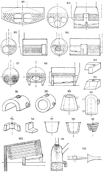
83. Has two central fire-boxes and side return-tubes.
The foregoing box patterns are rapidly going out of use, as unsuitable for the higher pressures prevailing with compound engines.
84. Cylindrical boiler, with three fire tubes and three sets of return tubes. This form is much used, the surfaces requiring stays being very limited. It is made with double fire-boxes as shown, or with single fire-box, as No. 81.
85. Cylindrical single flue and return-tube.
86. Cylindrical single flue and multitubular.
87. Cylindrical double flue and multitubular, longitudinal section similar to No. 86.
88. Cylindrical saddle boiler, multitubular, used for shallow vessels, launches; &c.
HOUSEHOLD BOILERS.
89. Kitchen “ell” boiler.
90. Kitchen or back boiler, for ordinary grates.
91. “Saddle” boiler. The varieties of this type are legion. Every conceivable cross-bridge, water-way, tube, and flue has been added to it by various makers. See Messrs. Graham and Fleming, and other makers’ Lists.
92. Annular cylindrical greenhouse boiler.
93. Annular conoidal greenhouse boiler.
94. Vertical cylindrical, closed top greenhouse boiler.
The last four are types of the greenhouse boilers most in use. They are usually of wrought iron, and all seams welded.
95. Back boiler for ordinary register grate.
96. “Boot” boiler.
97. Scullery, or wash-house boiler.
98. Scullery, or wash-house boiler, heated by steam. In public laundries these are usually rectangular in plan.
99. Coil boiler, used for small greenhouses, &c.
100. Sectional, or “Tubulous” boiler. Root’s, and others, are on this principle. They are constructed of simple pipes and T or L pieces, usually bolted together.
Section 7.—BLOWING AND EXHAUSTING.
Some of the mechanical blowers are too well known to need illustration here; such are the ordinary Beam Blowing Engine, as in use for blast furnaces, Vertical Blowing Engine, and Horizontal Blowing Engine. In all these a cylinder and piston form the blowing device. Nearly every form of rotary engine (see Section 75) may, by reversal, be converted into a blowing machine. See Root’s patent, No. 1307; Baker’s, 1325, and others in common use. Fans, centrifugal, (see No. 1337) are still the commonest blowing machines, and are especially suited for light pressures and large volumes of air; but for pressures of from 1⁄2 lb. per square inch and upwards, the rotary or cylinder types are best. The following are devices not so well known, but sometimes useful:—
101. The “Trompe,” or water-jet blower. Water under pressure is discharged through a rose into a funnel-shaped inlet, carrying with it a quantity of air (see Section 45); the water runs off at an overflow, and the air is led away by a pipe.
102. Steam-jet blower. (See Section 45.)
Larger plate.
103. Organ bellows. The lower “feeders” pump alternately into the double-tier upper “reservoir,” which has the upper set of ribs inverted, as shown, to equalise the pressure throughout its rise. The reservoir is loaded with weights to the required pressure.
104. Smiths’ bellows, either circular or hinged at one side.
The valves used for bellows are plain flap valves faced with leather similar to No. 1619.
105. Bell, or gasometer blower, for light pressures and large volumes.
106. Regulator, or reservoir, for blowing engines to steady the blast. The weighted piston serves the same purpose as an air vessel to the ordinary pump.
107. Disc blower, with elastic diaphragm piston.
108. One-crank three-throw blower, for organs, &c., to give a continuous blast. The three feeders deliver into the central triangular box.
Section 8.—BEDPLATES, FOUNDATIONS, AND FRAMING OF MACHINES.
The skeleton framing of a machine for any purpose should be rigid, as light as is consistent with strength and stability (in some cases weight is necessary to minimise vibration), and the ribs, or members of the frame, should be so disposed as to afford the requisite support for all bearings, centres, &c., without redundance; and lastly, symmetry, and a certain degree of elegance and proportion, are desirable. The illustrations are necessarily typical only, and suggestive.
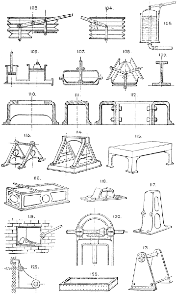
109. Girder section bedplate for horizontal distributed bearing, as in a horizontal engine. It may be used double, and the two parts connected by cross pieces and bolts, as No. 112.
110. Open box bedplate.
111. Closed box bedplate.
112. Double box bedplate with cross tie pieces.
Square or rectangular bedplates are usually of similar sections, stiffened with ribs underneath, and generally cast in one piece.
113. Side frame and distance rod construction, suitable for light machines.
114. Side frames and cross bars on a base plate. This forms a more rigid construction than No. 113.
115. Table and legs.
116. Rectangular openwork box framing. Useful for machines with several cross shafts.
117. Hollow standard for hammers, vertical engines, and any machine raised above the floor.
118. Soleplate and standard for pedestal bracket, &c. Admits of being detached without disturbing the foundation.
119. Wall box for shaft bearings, &c.
120. Arched crosshead for double bearing, bevil gear, &c.
121. Wrought-iron sideplate and distance rod construction.
122. Wall bracket, with wall flange, or tongue, to take the vertical strain.
123. Wrought-iron rectangular bedplate.
Larger plate.
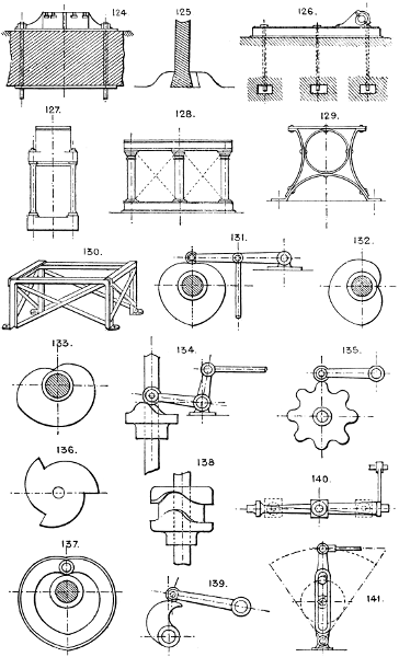
124. Base plate for column, &c., with concrete foundation. The bolts are usually T headed (see No. 1404), in open recesses, so as to be easily removed without disturbing the base plate.
125. Dovetail and key fixing for brackets, bearings, or any separate detail of framing.
126. Foundation for box bedplates.
127. Vertical columnar, or distance rod construction, used for marine engines, vertical engines, presses, &c.
128. Plinth, column, entablature, and cross bracing, used for beam engines and machinery of a straggling kind with many detached parts.
129. Flat bar side framing, strong, light, and cheap, but not very rigid.
130. Wrought-iron L and flat bar rectangular frame, suitable where great rigidity is not needed, but where cast-iron is not safe or desirable.
Wrought-iron is becoming much more largely employed for the framing of general machinery than heretofore, and it is customary in many cases to supplement a cast iron base or frame with wrought iron or steel bars.
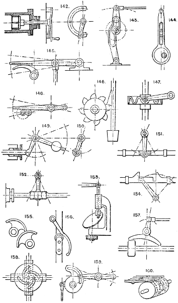
Section 9.—CAM, TAPPET, AND WIPER GEAR.
For producing, from plain circular, or reciprocating motion, variable speed or motion, also intermittent and every kind of irregular motion. Cams are either open or covered. Nos. 131, 132, and 133 are open cams; Nos. 137 and 138, covered cams.
131, 132, & 133. Three forms of the “heart” cam, for giving a regular or intermittent vertical motion to a lever end.
134. Crown cam for vertical shaft.
135 & 136. Jumping cams.
137. Covered heart cam.
138. Covered crown cam.
139. Wiper and lever motion.
140. Twisted bar with sliding bush, which travels from end to end of the bar, and being prevented from turning, causes the bar to turn on its axis to the amount of its twist.
141. Crank pin and slotted lever; gives a variable speed with quick return.
Larger plate.
142. Spiral radius bar for opening valve. The valve is lifted off its seat by the radial motion of the lever against the inclined radius bar.
143. Crank pin and slotted lever motion, with slot arranged for irregular or intermittent motion.
144. Eccentric and slotted arm. The pin at the top of the arm has both a vertical and horizontal motion, causing it to trace an ellipse, the pin upon which the slot runs being fixed.
145. Wiper and lever motion, with rubbing plate; used for Cornish valves, &c.
146. Stamp mill.
147. Scroll cam.
148. Crank and lever, intermittent or continuous motion.
149. Piston, or valve rod and lever motion.
150. Similar movement, but with anti-friction roller on end of lever.
151. Rod and lever reciprocating motion, with anti-friction roller.
152. Similar movement, with a socket forged in the rod and the end of lever rounded to allow for angular motion.
153. Diagonal disc cam, or “swash plate.”
154. Motion for belt shifting with dead travel at half stroke. This allows the lever to move a certain distance on each side of the centre without moving the belt shifting bar.
155 & 156. Sectors and bent lever, used on Cornish engine valve gear.
157. T lever valve motion, used in rock drills, some forms of steam engines, &c.
158. Four-bolt camplate, used for screwing dies, locks for fireproof safes, &c.
159. Slot, cam, and lever motion.
160. Barrel motion for musical instruments, looms, &c., in which the barrel is provided with pins or staples to lift the respective levers.
Larger plate.
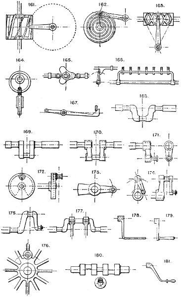
161. Drum with spiral vanes of long pitch, operated by a revolving arm on a shaft at right angles to the cam shaft, used for intermittent circular motion.
162. Volute and lever.
163. Double screw, for converting circular into reciprocating motion; has a right and left hand screw thread, and a shuttle attached to the lever end shaped to fit the thread, and capable of swivelling to turn the angle for reversing.
164. Eccentric ring and roller motion, for converting circular into reciprocating motion.
165. Triangular cam. Gives three reciprocations to the sliding bar in one revolution of the cam.
166. Fan for giving motion to several rods or arms at one time, used for organ composition pedal movement, &c.
167. Crossed lever motion with inclined contact surfaces, the levers being at right angles to one another.
Section 10.—CRANK AND ECCENTRIC GEAR.
168. Bent crank of round section; retains the fibre and strength of the metal.
169. Square forged crank. The crank arm is usually forged solid and the slot cut out by machine.
170. Built-up crank. There are other methods of building them. See Mechanical World, December 1885. See also No. 182.
171. Single crank, usually of wrought iron, but often made with cast-iron arm.
172. Disc crank. This form is generally adopted when cast iron is employed, and the counterbalance weight cast upon it, to balance the connecting rod, &c.
173. Counterbalanced single or double crank.
174 & 175. Two forms of crank pin eccentrics; sometimes used to drive the slide valve instead of the ordinary sheave and strap, as No. 183.
176. Crank pin set in a boss formed on the driving wheel.
177. Double rod crank.
178, 179, & 181. Hand cranks. These should always be fitted with a loose ferrule of wood for the hand if possible, as much power is lost by the slipping of the hand to change its grip as the crank revolves.
180. Solid three-throw crank shaft, turned out of a solid forging.
Larger plate.
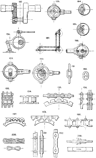
182. Built crank. Several modifications of this are in use for large marine shafts.
183. Solid sheave eccentric.
184 & 185. Split sheave eccentrics.
Large eccentrics cause great loss from friction, unless provided with friction rollers in the sheave; but are sometimes used to avoid an additional crank in shaft.
186. Eccentric motion for multiplying travel of eccentric by leverage.
187. Crank motion to turn an angle instead of bevil gear and shaft, the cranks being of the form of Nos. 174 or 175.
188. Shifting or variable throw eccentric. The sheave is slotted to fit the shaft, and its throw is governed by a disc having a spiral slot and locking bolt.
189. Another form of shifting eccentric. The sliding block is arranged to lock in any part of the slot in the sheave.
190. Another form of shifting eccentric, in which the sheave is loose on an eccentric boss cast with the worm wheel, and is revolved by the worm, the bearings of which are fixed to the sheave.
See also Nos. 606, 712, 720, 728, 729.
See also Sections 40 and 79.
Section 11.—CHAINS AND LINKS.
For Hooks, Swivels, &c., see Section 43.
191. Ordinary long or short link chain. It is sometimes made to exact pitch to fit a snug or sprocket wheel. See Nos. 1250 & 1251.
192. Stud link chain.
193. Flat chain for use on flat rim double-flanged pulley.
194. Square link pitched chain for sprocket wheel.
195. Stamped link pitched chain and special sprocket wheel.
196. Ordinary pitched link chain. Links drilled to templet.
197 & 198. Pitched chains to drive wheels with ordinary and special teeth.
199. Another form of square link chain.
200. Stamped link chain, for light purposes.
201 & 202. Long link flat suspension chains.
203. Gib and cotter attachment for long link flat suspension chains.
Larger plate.
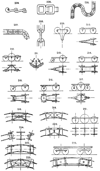
204 & 205. Drive chains. See Ewart’s patent, No. 2752-76, and others. These chains are replacing belts for many purposes, as they give a positive drive, do not stretch so much, and last longer, besides which they are easily detached at any point, and a damaged link can be readily replaced.
206 & 207. Thrust chains, with friction rollers at each junction, used in hydraulic multiplying cylinder gear in some cases.
208. Ewart and Dodge’s patent chain, with renewable seatings between the links.
Section 12.—CARRIAGES AND CARS.
The design and details of these must always be suited to circumstances. We only propose here to indicate the various types of under-framing and wheels in use, and to give sketch sections of bodies or cars for different purposes.
UNDER-FRAMES.
209. Two-wheel suspension car for single rail or wire rope, used commonly on some kinds of cranes. See Section 18.
210, 211, 212, & 213. Three-wheel cars. See also the various types of tricycles in use.
214, 215, 216, & 217. Various forms of four-wheel under-frames, with and without swivelling bogies.
A car with four wheels arranged as No. 217, but with the leading and trailing wheels slightly raised off the ground, is used as a goods car or hand truck, and is very readily swivelled about, running, of course, actually on three wheels only.
218. Five-wheel under-frame, with and without swivelling bogies.
219 & 223. Plans of six-wheel cars, with swivelling gear for curves; the centre pair having end play, swivel the leading and trailing axles by means of the jointed stays.
220. Plan of four-wheel car, with swivelling gear for curves.
221, 222, & 224. Six-wheel cars, the latter with leading and trailing swivelling bogies.
225. Eight-wheel double-bogie under-frame. This is the plan usually employed in long cars; each bogie is free to swivel independently, and is centrally loaded.
Larger plate.
226. Ten-wheel double-bogie under frame, the centre pair to have end play or broad flat tyres.
227. Twelve wheels and three bogies. The centre bogie must have end play, either as in Nos. 222 or 226, or with transverse rollers between the bogie and frame.
Note that in Nos. 221, 223, & 224 the centre pairs, if running on rails, must have either end play in the bearings or flat broad tyres.
228. Open passenger car, either with transverse or longitudinal seats.
229. Covered passenger car, with either longitudinal or transverse seats.
230. Passenger car, with outside and central longitudinal seats.
231. Passenger car, with upper and lower longitudinal seats.
232. Passenger car, as No. 231, but with seats reversed.
233. Passenger car, for one-rail railway.
234. Passenger car, similar to No. 230, but with seats reversed.
235. American plan of passenger car, with transverse seats and central gangway.
236. Goods cars, low sided.
237. Covered or box wagon.
238. Hopper wagon for discharging below.
239. Side discharge hopper wagon.
240. Side tip (or end tip) three-centre wagon.
241. Tip cart.
242. Tip wagon.
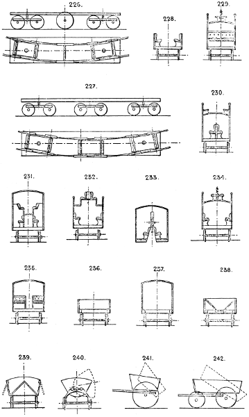
Larger plate.
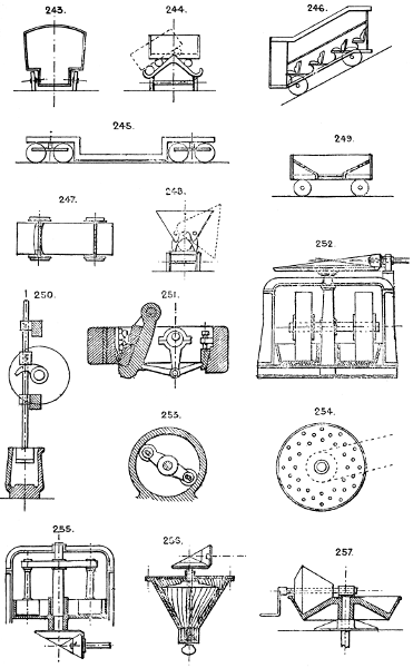
243. Furniture wagon.
244. Grafton’s patent side tip wagon.
245. Long truck for boilers, &c.
246. Incline car for passengers.
247. Segmental swivelling bearings, used instead of a swivelling bogie and centrepin.
248. Hudson’s patent tip wagons, with three centres.
249. Hopper wagon, with central discharge.
Section 13.—CRUSHING, GRINDING, AND DISINTEGRATING.
250. Stamp mill, generally arranged in a battery of 4 or 6, for gold and other ores.
251. Stone-breaker, with chilled iron jaw faces and toggle or knapping motion. See Blake’s, H. R. Marsden’s, and other modifications in common use.
252. Double edge-runners. Sometimes driven below. In some designs the rollers revolve, and in others the pan revolves and the roller shaft is stationary.
253. Lucop’s patent centrifugal pulveriser.
254. Carr’s patent disintegrator. In this machine, each ring of bars is driven at a high speed in opposite directions inside a casing, the material being broken by the rapidity and intensity of the blows it receives.
255. Horizontal centrifugal roller mill. The material is crushed between the rollers and the shrouding of the pan by the centrifugal force of the rollers, which are suspended from a crosshead.
256. Cone roller mill, with vertical spindle.
257. Cone roller mill, with horizontal spindle and conical pan.
Larger plate.
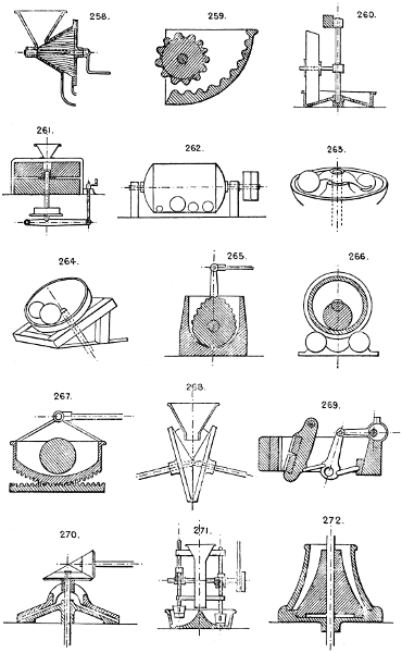
258. Enclosed cone roller mill, with horizontal spindle and spirally grooved roller and casing.
259. Toothed sector mill.
260. Conical edge runner and pan.
261. Ordinary flour mill. The material is fed in the centre, passes between the stones, and falls out into the outer casing.
262. Rattle barrel, for cleaning and burnishing articles by mutual attrition; sand or emery is sometimes used to assist the process.
263. Ball and pan mill, for crushing ores, &c. The balls are carried round by a cross arm fixed to the central spindle.
264. Inclined ball and pan mill.
265. Oscillating mill.
266. Drum and roller revolving mill.
267. Cradle and roller mill.
268. Cone disc mill; the cones being inclined axially to one another, the material is crushed at the lower side of the cones.
269. Another form of stone breaker with toggle motion.
270. Horizontal cone plate mill.
271. Revolving stamp and pan mill for ores.
272. Vertical cone mill.
273. Revolving pan and ball mill.
274. Planishing discs for accurately rounding iron bars. See the patent rolled shafting in use, manufactured by the Kirkstall Forge Co. and others.
275. Vertical cone grinding and crushing mill. The vertical shaft has an eccentric motion at the footstep, giving a swaying rotatory motion to the grinding cone.
276. Crushing rollers with spring bearing.
Section 14.—CENTRIFUGAL FORCE, APPLICATIONS OF.
277. Centrifugal drill. The cross bar A is alternately pressed down and allowed to rise, the strings winding on the spindle alternately in opposite directions by the momentum of the fly-wheel.
a. Fly-wheel. Use: to receive and store redundant motive power, and give it off again when the motive power falls below the average.
b. Centrifugal hammer. One or more hammers are loosely jointed to a revolving boss, and strike rapid blows on an anvil fixed in the path of their circumference. See No. 1915.
c. Pulverising machines. See Nos. 253, 254, 255.
d. Speed governors. See Section 41.
e. Cream skimmers have a pan revolving horizontally in which the new milk is poured. The cream travels to the outer edge and runs over into a receiving trough.
Larger plate.
f. Centrifugal dryers. Manlove and Alliott’s, also Robinson’s continuous feed ditto, are examples.
g. Some forms of turbine. On the principle of Hero’s Eolipile, No. 1696.
h. Swings. Roundabouts. Various toys. The Gyroscope and tops constructed on its principle.
i. Juggling and other tricks performed with pivoted plates and other common articles.
j. Rattle barrel, or revolving drum, for polishing small castings, &c., by centrifugal motion and mutual friction, similar to No. 262.
k. Various machines for grading wheat, grain, and seeds. See No. 475.
l. Centrifugal filter for sugar; a modification of the centrifugal drying machine.
m. Centrifugal pumps are forms of fans or turbines (see Section 90); Gwynne’s, Schiele’s, Andrews’, and others are examples.
Section 15.—CLUTCHES.
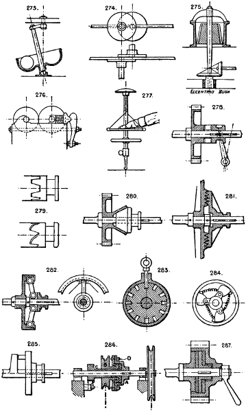
278. Common jaw clutch sliding on a feather key, the loose half being cast on the boss of a wheel.
279. Two forms of jaws for ditto.
280. Cone clutch. Screw gear should be used to operate this, as it is liable to “seize,” and there is considerable end pressure on the shaft to be allowed for.
281. Face (friction clutch) with V grooves. See remarks to No. 280.
282. Friction clutch with three or more segments. See also Nos. 38 and 59.
283. Pin and hole clutch. The pin and holes can of course be made parallel to the shaft instead of radial.
284. Cam clutch, used for dexter treadles, also for reciprocating motions driving one way and running loose the opposite way. See also Section 62, Nos. 1135, 1178, &c.
285. Crank pin and arm driver.
286. Pickering’s self-sustaining clutch for hoists. The box A only is keyed to the shaft, and drives the chain wheel and sleeve B by jamming it with the flange of the ratchet-wheel sleeve C by the sliding action of the toothed faces formed at D on the disc and flange of the sleeve B, these teeth being of the ratchet form.
Several other forms of this clutch are in use. Edwards’, Stevens and Major’s, and others may be consulted.
287. Disc friction clutch, with intermediate leather discs and screw clamping appliance, only the central disc is keyed to the shaft, the others run loose. Mather and Platt’s and Addyman’s patent friction clutches are examples.
Numerous forms of friction clutches are in use, modifications chiefly of Nos. 38, 59, and 282. See also Section 5.
Larger plate.
Section 16.—COUPLINGS FOR SHAFTING.
288. Ordinary flanged coupling, usually made so that the end of the shaft forms a spigot joint with the opposite half of clutch.
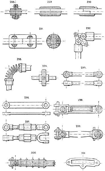
289, 290, 291. Sleeve couplings. See also No. 1430 and Section 57. Butler’s patent frictional coupling, Kirkstall Forge Co., Leeds, Seller’s double-cone vice coupling, and others, are sleeve couplings.
292. Angle coupling on Dr. Hooke’s principle. - See also Nos. 33, 34, and 732.
293. Flexible angle coupling for light work.
294. Flanged coupling, with cross feather or key. This plan gives great torsional strength, especially if the coupling flanges are forged solid with the shafts.
Section 17.—CONNECTING RODS AND LINKS.
295. Turned and finished link without any adjustments; ends may be solid, or forked as No. 297.
296. Flat link of similar description, with raised bosses for facing and wear.
297. Adjustable link, with right and left hand screw coupling. Lock nuts may be added to prevent the coupling working back.
298. Strap link, fitted with brasses, gibs and cotters, and distance bar. In this link the wear of brasses is all taken up one way by the gib and cotter; therefore, if great accuracy in the distance apart of centres is necessary, gibs and cutters should be fitted at both sides of one pair of brasses, or No. 299 adopted.
299. Turned link with adjustable end brasses. The forked end should be used where there is the greatest amount of wear.
300. Wood connecting- or pump-rod with wrought-iron strap ends, fitted with brasses, gibs, and cotters. Much used on mining pumps.
The shafts or rods are sometimes of cast iron of cross or T section, but are usually of a circular or flat section and swelled in the middle, similar to No. 299. See Struts and Ties, Section 102.
301. The most usual form of shifting link for link-reversing gear, generally got up bright all over.
Larger plate.
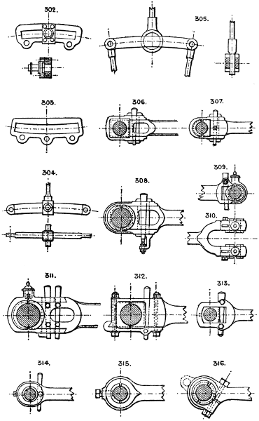
302. Similar link, but having the point of suspension on a side pin, fixed by screws to the link, and raised from it sufficiently to allow the sliding block and pin to pass under it.
303. Reversed curve link.
304. Solid bar link, sometimes adopted for cheapness and simplicity, the valve rod and eccentric rods having of course forked ends.
305. Double bar link. This is also a simple and cheap construction; the bars are plain, the rod ends single, and the block turned large enough to have a recess on each side to fit the links.
306. Strap head connecting rod end, with square brasses, double gibs and cotter.
307. Strap head connecting rod end, but with rounded end and set screw fastening for cotter.
308. Similar to the last, but with screw cotter adjusting device for the brasses.
309. Solid end rod. The brasses take out sideways.
310. Forked end rod.
311. Strap end for heavy rods, having cotter for tightening the strap to the V’s in the rod end. The oil cup is often forged and turned solid on the strap, as shown.
312. Rod end with side strap. The brasses take out transversely by taking off the side strap.
313. Solid end and double set screw fastening for cotter.
314 & 315. Solid ends for small rods. The brasses are usually secured by a set screw.
316. Solid end, split with screw bolt tightening device; may be hinged as shown by dotted line.
Larger plate.
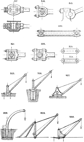
317. Covered solid end for crank pins, with screw adjustments for brasses.
318. Common forked rod end, with cap.
319. Hook bolt attachment for gudgeon; sometimes useful where there is thrust only on the gudgeon.
320. Double connecting rod, in which the rods form also distance rods and bolts for the heads, which are in halves and fitted with brasses of the ordinary type.
321. Marine type of rod end, having solid end, square brasses and cap.
322. Marine head, in which the brasses are extended to form the central block in halves, the rod end being of T shape and bolted through the brasses and cap.
323 & 324. Plain links.
There are innumerable varieties of the illustrated types of heads in use, every engineer having his own design.
Section 18.—CRANES, TYPES OF.
Our object here is to indicate or suggest general design or arrangement only, from which a selection can be made to suit requirements.
325. Is the common type of wharf crane with fixed post, the base plate being well bolted down to a solid mass of masonry.
326. Is also a common type of wharf crane, but with the post revolving in a footstep and base plate; this gives a better base than No. 325.
327. Has no post, but a revolving frame and base plate with front and back friction rollers, and a centre pin.
328. Post and jib in one piece, usually of wrought iron. A balance weight is fixed at A to balance the overhanging jib.
329. Swing derrick crane, generally of wood. The jib turns three-fourths of a circle, and the two guys are fixed at an angle of 90° apart, and well secured by anchoring or loading, often made with very long jib for builder’s work.
330. Wharf crane, with centre tension bolt instead of crane post. In this arrangement there is a vertical tension on the centre bolt and thrust on the foot of jib.
Larger plate.
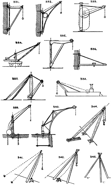
331. Warehouse wall crane.
332. Warehouse wall crane, with high jib-head.
333. Whip crane, chiefly used in goods sheds. The barrel is sometimes worked by an endless handrope as shown, and sometimes by a second rope and drum with a hand crank as No. 1209.
334. Portable hand crane, with balance weight. The balance weight can be shifted in or out to balance the load.
335. Foundry crane, sometimes with travelling carriage on the jib, as No. 336.
336. Swing bracket crane and traveller, usually formed of flat bars on edge; used only for light loads, for smiths’ shops, &c.
337. Wharf derrick, to turn an entire circle, similar to No. 329, but employed for heavy loads.
338. Floating derrick.
339. Light balance crane.
340. Trussed jib crane, with centre tension bolt.
341. Simple derrick and winch, with two guy ropes; for temporary purposes only, and may be easily shifted about.
342. Sheers and winch.
343. Tripod and winch.
344. Sheers with screw adjustment to back leg. This design is adopted for very heavy lifts, such as loading heavy machinery, shipping masts, boilers, &c.
Larger plate.
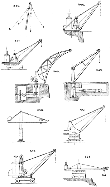
345. Four-guy derrick and winch, used for fixing columns, bases, masonry, &c.
346. Fixed post steam crane, for wharfs, piers, jetties, harbour works, &c.
347. Portable steam crane, very largely used on wharfs, piers, &c., and sometimes fitted with travelling gear in addition to hoisting and slewing motions.
348. Wharf crane, with fixed engine, centre bolt, and trussed arched jib. This is a very good type, as the ground is kept clear for goods, &c., and of course all motions, hoisting, lowering, and slewing are controlled from the crane above ground by hand levers.
349. Hydraulic wharf crane, with fixed post. The common type universally used in docks, &c., with the ordinary form of multiplying hydraulic cylinder and chain gear; the valve for controlling its movements is operated by hand levers extending up through slots in the floor; the slewing is performed by a separate cylinder and chain gear, with a distinct controlling lever. See Sections 42 and 83.
350. Hydraulic short lift ram, centre crane, and traveller, employed chiefly to raise the ingots out of the casting pits of Bessemer steel works. The ram is of course subject to severe cross strains, and many designs provide an overhead guide or support for the ramhead.
351. Automatic balance crane, portable or fixed; the position of the fulcrum varies with the load.
352. Steam multiplying cylinder crane, in which the ram is forced out by steam pressure, acting either directly or by an intervening body of water.
353. Breakwater swing crane.
Larger plate.
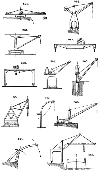
354. Overhanging travelling crane, for use on breakwaters, &c.
355. Overhead hydraulic travelling goliath, to span a railway; has slewing motion and a balanced jib.
356. Single rail crane with top guide rail.
357. Overhead traveller on gantry.
358. Goliath.
359. Steam overhead crane, with carriage to span a railway. Largely used on dock wharves, &c., as they give a high lift and do not encumber or encroach on valuable quay space.
360. Hydraulic cylinder post crane; sometimes adopted instead of the type No. 349.
361. Heavy hydraulic crane, with suspended cylinder; employed for work of the very heaviest class.
362. Ship’s Davit.
363. Balanced jib post crane, no tie rod. The weight must be sufficiently heavy to balance the jib and load.
364. Hydraulic strut jib crane. The load is raised by raising the jib.
365. Overside dock crane, for discharging from ships into barges. The overhang being very great in this design, it must be provided with a heavy frame or balance weight.
366. Wagon tip crane, for loading vessels.
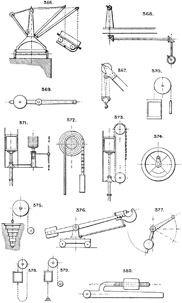
367. Double sheave 4 to 1 purchase for crane jib. See also Section 69.
Section 19.—CONVEYING MESSAGES.
Messages can be conveyed by—
1.
Speaking tube; for distances up to say 300 feet, 3⁄4″ to 1″ bore tubes.
2.
Telephone; any distance.
3.
Telegraph; any distance.
4.
By signals—(a) Wire or cord and bell; (b) sight signals, such as the semaphore, lamps, heliograph, flags, and other devices; (c) by sound, such as a bell, trumpet, siren, whistle, &c. See Section 105.
5.
By pneumatic despatch: that is, by forcing a piston carriage containing the message or small parcel through a tube by compressed air.
6.
Carrier pigeons.
1. Speaking tube; for distances up to say 300 feet, 3⁄4″ to 1″ bore tubes.
2. Telephone; any distance.
3. Telegraph; any distance.
4. By signals—(a) Wire or cord and bell; (b) sight signals, such as the semaphore, lamps, heliograph, flags, and other devices; (c) by sound, such as a bell, trumpet, siren, whistle, &c. See Section 105.
5. By pneumatic despatch: that is, by forcing a piston carriage containing the message or small parcel through a tube by compressed air.
6. Carrier pigeons.
368. Signalling dials and bevel gearing.
Larger plate.
Section 20.—COMPENSATING AND BALANCE WEIGHTS.
It is of the utmost importance that every revolving or reciprocating part of any machine should be as nearly as possible balanced, to obtain smooth running with the least amount of wear.
The following are types of the most important devices and their applications:—
369. Balanced lever, having a sliding cheese or ball weight fixed with a set screw.
370. Balanced cage of hoist. It is usual to over-balance the cage to divide the work between the up and down journeys in hand-power lifts to assist the load; but in power and hydraulic lifts the cage is under-balanced so as to descend when empty.
371. Hydraulic balance lift, in which the dead or constant load of cage and ram are nearly balanced by a loaded piston in a supplementary cylinder; to raise the loaded cage the pressure water is admitted to the upper side of this piston. Many varieties of this type are in use; see Ellington’s, Johnson’s, Stevens and Major’s, Waygood’s, and other patent lifts.
372. Variable volute compensating balance for revolving shutters, blinds, curtains, &c., to maintain an even balance in all positions, The weight chain is as thick as the coiling shutter on blind, so that the acting radii of the shutter and weight are always proportional.
373. Variable compensating balance for hydraulic lift rams, to compensate for loss of immersion of the ram as it ascends (Berly’s patent). See also Stevens & Major’s patent, where bell-crank levers and weights are employed instead of loaded chains. See No. 383.
374. Balanced fly-wheel. For balanced cranks, see Nos. 172 & 173.
375. Increasing balance by sections, lifted at intervals as the chain rises.
376. Balanced riveting machine. See Tweddell’s patents.
377. Variable lever balance. For balanced cranes, see Section 18.
378. In deep lifts, to balance the weight of chain or rope, it is made endless.
379. Another method. The loose chain hung from cage is of the same weight per foot as the lifting chain.
380. Balance weight on a screw arm for adjustment, employed on weighing machines.
Larger plate.
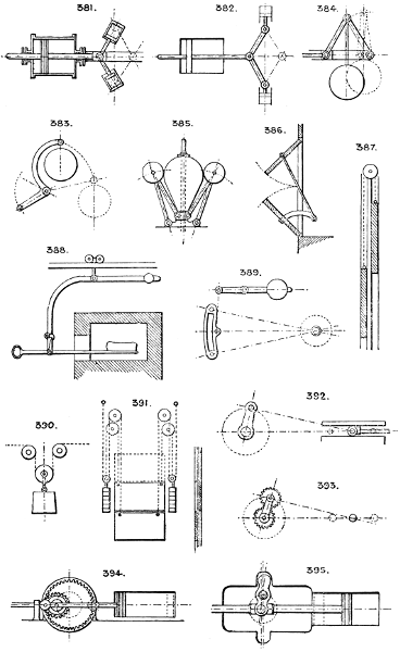
381 & 382. Worthington’s compensating air cylinders, employed on direct-acting horizontal pumps, working expansively, in lieu of fly-wheel. The oscillating or vertical cylinders are air or spring pistons, absorbing power the first part of stroke and giving it out during the latter part.
383. Variable balance weight by bent lever.
384. Variable balance weight by double links and sliding joints.
385. Dawson’s compensating governor. See Mechanical World, August 25th, 1888.
386. Balanced doors, hinged vertically.
387. Balanced sashes, or vertical sliding doors.
388. Method of balancing a bloom in charging or withdrawing from a furnace, or any similar use.
389. Balance for link motion.
390. Weight to keep a cord or rope in tension.
391. Mode of balancing two sliding doors so that they rise and fall at proportionate speeds.
Hoisting and winding engines (see Nos. 1222, 1223) are balanced by having an ascending and descending cage, and two ropes, one winding on as the other winds off the drums.
Double cage hoists similarly balance themselves. Heavy slide valves, and other reciprocating parts of steam engines, are balanced by small steam pistons. See Nos. 1651-1654.
Foot treadles, when required to always stop at a point off the dead centre, have a balance weight fixed to fly-wheel, at right angles to the dead centre.
A water tank is often used to serve as a counterpoise, or balance, and may be made variable by varying the quantity of water by a siphon or other device.
For Balanced Valves, see Section 89.
Section 21.—CIRCULAR AND RECIPROCATING MOTION.
392. The ordinary type of piston-rod and crank motion as universally used.
393. Watt’s substitute for the above, or “sun-and-planet” gear. Note that the crank shaft revolves twice for each double stroke or revolution of the engine. The crank being a loose link only, the planet wheel does not revolve.
394. Epicycloidal parallel motion and crank. The pinion is one-half the diameter of the wheel on pitch line, and the connecting pin is fixed on the pitch line of pinion.
395. Bernay’s patent crank motion; radius of crank = stroke × ·25.
Larger plate.
396. Slot and crank motion. The pin usually runs in a sliding block.
397. Segment pinion and double rack motion.
398. Rack and pinion. The pinion is sometimes made so as to be driven on one stroke and run loose on the other, by a clutch or ratchet motion, such as Nos. 1135, 1178, or their equivalents. See Section 62.
399. Hydraulic multiplying gear. See also Section 42.
400. Slotted crosshead and disc crank. The pin runs in a sliding block in a groove in the covered crosshead.
401. Stannah’s patent, works vertically; the fly-wheel centre A oscillates on the end of a link B, allowing the crank pin to run in a straight line.
402. Screw and fly nut. May be made to produce continuous rotary motion by fitting the nut with a clutch motion similar to 1135 or 1178, so as to grip the wheel only on one stroke.
403. Friction gear; the pinion is driven by the reciprocating rod and runs loose on the out stroke, the weighted lever with roller giving frictional grip on the in stroke.
404. Lever and roller crank pin.
405. Treadle motion, with cord and spring. For continuous rotary motion the pinion must be fitted as described with No. 402.
406. Ball and socket crank motion. The crank pin is always horizontal.
407. Segment lever, with cord and pulley.
408. Double geared cranks, used for driving rotary blowers, &c.
409. J. Warwick’s patent; circular motion converted into reciprocating by a diagonal sheave grooved as shown; the crank arm centre is in line with the centre of the sheave, as shown in dotted lines.
410. Rolling sectors, with thrust motion to crank pin. Used in Outridge’s box engine with double pistons; this gives a constant rectilinear thrust to the crank pin at all points in the stroke, and no part is in tension.
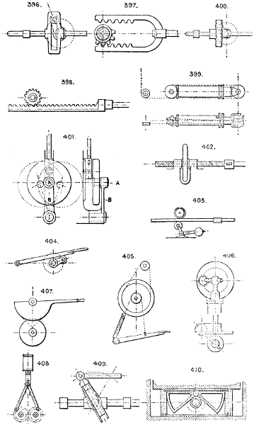
Larger plate.
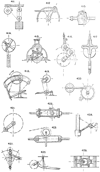
411. Weight and multiplying pulleys, used for clock motions, driving any light machines, &c.
412. Oscillating clutch arm and ring, silent feed motion.
413. Slot and roller motion for crank. The crank pin has a friction roller, which runs in a covered slot in the crosshead.
414. Trammel gear; one revolution of the wheel to two double strokes of piston.
415. Segmental vanes (in a semicircular case), driven by a disc crank and pin, running on the upper centre, giving motion by links to two arms fixed to the two vanes, which have independent motion. Used as a pumping or blowing machine.
416. Circular into reciprocating motion by revolving arm A carrying the two pinions, the point at end of arm B describes a vertical line four times the length of arm B, the large wheel C is fixed, and motion is given to the arm B. May be used as a piston rod and crank motion.
417. Trammel gear; the slotted cross moves in a right line.
418. Slot link and treadle, driving the pinion on both strokes by friction on the inside of link alternately at the upper and under sides.
419. Chain and roller treadle motion.
420. Reciprocating wheel and crank motion.
421. Velocipede pattern foot treadle.
422. Double crossheads, separated by distance rods so arranged as to allow the crank and connecting rod to work between them. See No. 681.
423. Mangle rack and pinion reciprocating gear. The rack moves in a right line, the pinion working round it by moving up and down the slot at each end of the travel of the rack.
424. Mode of connecting an oscillating lever by a sliding joint to any reciprocating part, such as a steam hammer head, engine crosshead, &c. See Nos. 893, 894.
425. Suspended treadle motion.
426. Eccentric and sliding bush motion for a double piston engine.
427. Rocking lever motion by gearing and a tied crank pin. The upper pinion drives the crank disc on the middle centre at each revolution, of which the lever with the gearing attached oscillates from side to side as shown.
Larger plate.
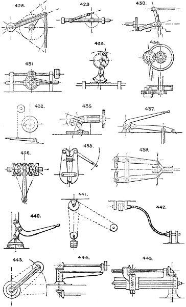
428. Crank pin and slotted lever for giving a variable speed to the connecting rod. See No. 1195.
429. Side gudgeon crank motion.
430. Bell crank and disc crank motion, the bell crank centre having horizontal as well as vertical movement.
431. Worm wheel and screw reciprocating motion by means of a tied crank pin. Useful for slow speeds.
432. Treadle, cord and pulley crank motion.
433. Circular into reciprocating motion, or vice versâ.
434. Another form of sun-and-planet gear. The ring is stationary, and the bush on which the planet wheel revolves is slotted to fit the ring; the planet wheel is fixed to the connecting rod end.
435. Bent shaft and arm motion.
436. Reciprocating motion by a return thread screw and lever.
See also Sections 62, 31, and 74.
Section 22.—CONCENTRATED POWER.
Multiplication of power by great reduction of speed is accomplished by the following devices, and various obvious modifications of them. Ordinary methods comprise—Gearing (see Section 84), the screw or compound screws (see Section 78), and the wedge and lever (see Section 53). By differential screws, Nos. 1379, 1380.
437. Compound lever.
438. Double toothed-cam and lever combination.
439. Double lever and link motion, with increasing pressure. The strains are self-contained, and this plan is very suitable where an increasing pressure is required.
440. Lever and toggle motion (see Section 63). Many variations are in use for stone breakers, &c. See Section 13.
Knapping toggle motion. See Nos. 269, 251.
Section 23.—CONVEYING MOTION TO MOVABLE PARTS OF MACHINERY.
Motion may be conveyed to such parts of a machine as require to be movable, or to distinct machinery which has no fixed location, by the following means:—
441. Is an endless rope or other round section belt, kept tight in any position in the plane of the driving pulley by a weighted pulley. In this plan the machine can be moved to any position in the plane of the driving pulley, the weighted pulley taking up the slack of the belt.
442. Flexible shaft for light driving. It admits of considerable flexure, and is useful for drilling and similar incidental driving purposes in difficult positions.
443. Radiating arm and belt. The movable machine can be driven at any point in circumference of the circle described by the arm head.
444. Similar plan, but driven by bevil gear instead of belt.
445. Bevil gear and feather shaft. The movable machine having a travel in a straight line the length of the shaft as well as a radiating motion.
Larger plate.
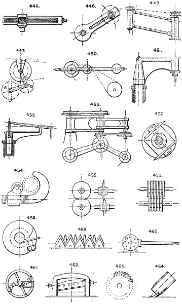
446. Screw and worm wheel gear, for the same purpose as 445.
447. The driven wheel A has a limited travel up and down the slot, the idle wheel B being kept in gear by the link suspension.
448. Idle wheel and slot. A common device for changing direction or speed in driving gear by connecting or disconnecting it with intermediate gearing between a fixed driving and a driven shaft.
449. Parallel motion radiating driving device, with a limited vertical travel and a radial motion.
450. Motion by belt is conveyed to a driven shaft having a radial motion in a vertical plane. Used for light drilling, emery wheels, &c.
451. Steam or hydraulic radiating arm and cylinder device.
452. Central cylinder and radiating lever motion.
453. Jointed radiating arms, with belt gear for conveying motion from a central spindle to one having a travel covering any point within a circle of the extreme radius of the jointed arms.
See also Nos. 348, 349.
Endless rubber or wire coil belts are used to give motion to machines having some amount of freedom of movement as regards the fixed position of the driving pulley.
Section 24.—CUTTING TOOLS.
Besides the ordinary cutting tools in use in the workshop, such as the chisel, gouge, plane, saw, drawknife, scissors, shears, scythe, and others, and which do not properly belong to machine devices, there are others, some of them mere modifications of the ordinary tools that are sometimes needed in the design of machines, and are illustrated here.
Other appliances are—Shears: see the ordinary shearing machines, bookbinder’s shears, No. 462, and other modifications. In some the shears are hinged at one end, in others the movable blade moves either with equal or unequal motion at either end by cam or crank motion (see 462.)
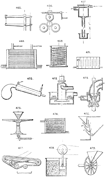
454. Pipe cutter, with V-edged cutting roller. Sometimes 3 cutting rollers are used. See No. 466.
455. Cutting discs, used for paper, sheet metal, &c.
456. Slitting discs, for cutting sheets into strips.
457. Revolving cutter head, for moulding, tenoning, and numerous wood working uses.
458. Hollow revolving cutter head, for rounding wood rods, broom handles, &c. See also No. 488.
459. Reaping machine cutters. A series of scissor-shaped knives, one set fixed and the other reciprocating.
460. Wire cutter discs, one fixed, the other attached to the hand lever, and having corresponding holes of various sizes in both discs.
461. Chaff machine, with revolving shear blades.
462. Guillotine shears.
463. Milling cutters.
464. Tubular machine cutter for wood working; easily sharpened, and can be revolved to present fresh cutting edges to the work.
Larger plate.
465. Fret saw or jigger.
466. Three-cutter tube shears, with worm gear motion.
Section 25.—CONDENSING AND COOLING APPLIANCES.
Their uses generally are to condense steam, to cool heated gases, air, or articles of food requiring a low temperature; distilling, and other purposes. For cooling purposes, compressed air machines are in most demand. The air is compressed in a cylinder, then cooled to ordinary temperature again in a surface condenser, such as No. 468, and then expanded into the cooling chamber, through a cylinder and piston, the expansion reducing its temperature usually to 10° or 20° below zero. Other cooling appliances are ammonia machines, fans, and blowers of all kinds, punkahs, or waving fans, freezing mixtures, &c.
467. Gravity condenser. The pipe should be 34 feet high or more, in which case no air pump is required, as the condensed steam and air are discharged below. In place of the pipe an air pump and foot valve are required, and are commonly used, as it is seldom convenient to have a vertical pipe 34 feet long with a water supply at the top.
468. Surface condenser, multitubular. The steam may be led into the tubes, and the water around them, or vice versâ.
469. Worm, or coil condenser, chiefly used for distilling.
470. Still condenser for essences, spirits, &c.
471. Condensing chambers for gases, &c. Horizontal or vertical.
472. Wimshurst’s condenser, requires no air pump. The exhaust comes down the vertical pipe, meeting the injection water from the side nozzle, causing sudden condensation and vacuum. The condensed water, &c., are blown out through the foot valves at each stroke.
473. Another form of ejector condenser in which the steam and water form a vacuum in the nozzle, and the water, &c., are discharged through a foot valve (not shown).
474. Tray cooler, or condenser; a series of water trays supplied from a tank above.
See Morton’s ejector condenser, which requires no air pump; Hayward’s exhaust condenser, which employs the water in suction pipe of a pumping engine to condense the steam. See Messrs. Tangye’s list. Water tube cooling coils are used for tuyeres and other hot surfaces.
Air-compressing and gas engine cylinders are water jacketed to carry off the heat of the compressed air or gas. Cooling by exposing a large surface to air is sometimes employed for exhaust steam on tram car engines &c., the apparatus consisting generally of numerous wrought-iron tubes or coils.
Section 26.—CONCENTRATING AND SEPARATING.
Sifting, riddling, and screening are treated of under Section 72. For concentrating ores many methods are in use, of which the water processes are the most important.
475. Circular revolving concentrating table. The lightest particles are discharged over the edge, and the heaviest remain in the centre.
The ordinary magneting machine, for separating particles of iron or steel from mixed borings, &c., consists of a series of magnets drawn through the material, and then through fixed brushes, which brush off the iron particles adhering to the magnets.
Larger plate.
476. Separating dust from grain, &c., by a current of air driven through the stream of material as it falls from hopper to hopper. See also Nos. 1268, 1270.
477. Ore concentrator; consists of an endless rubber belt with flanges (see No. 1082), having a slow longitudinal motion, and a rapid shaking motion, either sideways, as in the “Frue Vanner,” or endwise, as in the “Embrey” concentrator; a stream of water runs over the ore, the heavy particles settle on the belt, and the mud is washed off.
478. Jig for separating ores by motion of a piston in water, the heavy parts settle to the bottom and the light parts are removed at the top.
Filtration through various substances—as sand, charcoal, calcined ores, &c., is employed to separate suspended matter from liquids.
Separation by subsidence in a tank, similar to No. 1571, is employed for lime, &c.
Chemical deposition and evaporation are necessary in many cases.
Section 27.—CHOPPING, SLICING, AND MINCING.
479. Has a disc cutter with radial knives and slots; used for roots, &c.
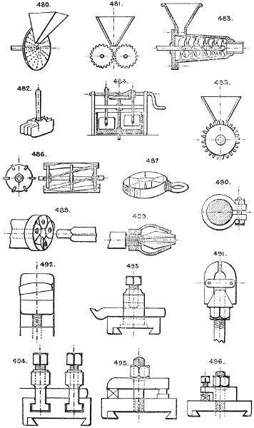
480. Disc cutter, with small knives wedged in separate holes, through which the cuttings escape in shreds.
481. Revolving cutter rollers.
482. Hand mincing compound knife.
483. Spiral tapered revolving cutter, in a conical case, having projecting knives on its interior. The type of the common mincing machine.
484. Two or more rectangular cutters, with vertical reciprocating motion in a revolving pan for mincing.
485. Single roller revolving cutter machine.
486. Revolving spiral cutters, as used in the common lawn mower, in conjunction with a fixed straight knife or shear blade.
487. Apple slicer and corer (cutter for). The apple is passed down through the cutter and divided into sectors and central cylindrical core.
See also Section 24.
Section 28.—CHUCKS, GRIPS, AND HOLDERS.
Common devices for gripping articles comprise the ordinary vice, tongs, pincers, pliers, joiners’ handscrew, cramp bench screw, parallel vice, instantaneous grip vice, &c.
488. Hollow chuck, with radial knives, for rounding wood rods. See also No. 458.
489. Barber’s patent grip for shanks of drills, brace bits, &c., having square taper shanks.
490. Collar grip and bolt, or set screw.
491. Cone and screw lever grip, with two or more jaws; with two jaws only it serves as a small vice.
492. Taper grip for vices.
493. Tool box, for lathes, planing machines, &c., with central revolving tool post and set screw.
Larger plate.
494. Tool box, with two tool stocks and set screws sliding in T grooves in the slide rest.
495. Tool box, with clamping screw and plate, which can be revolved to any angle.
496. A modification of 495, the tool being secured by set screws in the clamping plate.
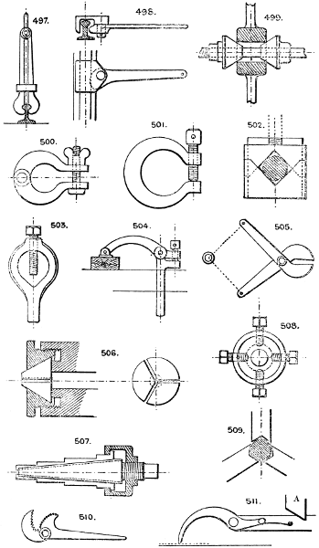
497. Rail grip for holding a crane, car, &c., down to its railway.
498. Cam-lever rail grip for safety gear on inclines; this is usually thrown into action by a spring released by the breakage of the hauling rope.
499. Cone centering grips for machine tools.
500. Hinged clamp, with screw and nut.
501. Fitter’s clamp or cramp.
502. V grip vice for round rods and tubes. This is frequently made with multiple V’s to hold cylindrical articles such as drills, &c., and is a common device for drill chucks.
503. Lathe carrier, for round rods, spindles, &c.
504. Bench cramp; employed to hold down to the bench work operated upon; the bench has a series of holes bored in it to receive the vertical leg of the cramp.
505. Grip tongs, used for draw benches, &c., the bite of the jaws increasing with the strain on the chain.
506. Split cone expanding chuck for rods, &c.; the centre cone is split into three or four parts, and the screwed ring or collet contracts the split cone upon any cylindrical article inserted in the central aperture.
507. Le Count’s patent expanding mandril, with cone and three sliding feathers which are fitted into dovetail grooves in the conical mandril. The travel of the feathers being limited, they are provided with steps to take various sizes of holes.
508. Bell chuck and set screws for lathes.
509. Three jaw grip, or stay bearing, used as a steady for long shafts or spindles.
510. Pipe tongs, self gripping; there are several modifications in use.
511. Paper grip, used for holding sheets of paper; released by striking a stop A at any point in the travel of the machine.
Larger plate.
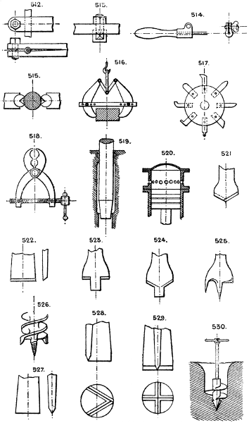
512. Split bar grip, or tool holder.
513. Eye-bolt tool holder.
514. Hand pad for holding small tools.
515. Self-adjusting jaws for round articles.
516. Adjustable gripping tongs for lifting heavy stones, boxes, &c. See also No. 761.
517. Revolving tool post, or head, to carry a variety of tools, each being required in use in a certain order, as in special repetition turning work.
518. Double screw gripping tongs.
See also No. 944, 912, 918, 917, 919, 923.
The ordinary three or four-jaw chucks, wood chucks with centre screw or fork, and numerous varieties of self-centering chucks, are well known. See tool makers’ lists.
Spindle grips, Nos. 917, 918, 919.
There are numerous forms of three and four-jaw chucks, both with universal or centering motions, and with independent jaws. See Horton’s, Cushman’s, the Sweetland, Pratt and Whitney’s, Westcott’s and others, chiefly American.
These are various combinations of the scroll (No. 1384) and screw jaws, as in the ordinary dog chuck. See also Nos. 1378 and 1381.
Section 29.—CUSHIONING.
For checking the impact of a blow, or more generally the momentum of a heavy moving part of a machine. The devices in use comprise (a) springs, see Section 80; (b) air cylinder, see No. 1480; (c) pistons driven by elastic fluids, such as steam and air, can be cushioned by imprisoning a portion of the fluid at each end of the cylinder; (d) brakes of various kinds, see Section 5.
519. Hydraulic cushion. The descending ram, by its tapered end, closes gradually the discharge outlet for the water.
Hydraulic buffer stops are constructed on this principle.
520. Cushioning device, at the upper end of a steam-hammer cylinder. Should the piston pass the exhaust holes, the steam above is imprisoned, and checks the piston without shock.
Section 30.—DRILLING, BORING, &c.
Besides the ordinary tools in use, as gimlets, bradawls, pin and brace bits, augers, &c., which do not need description, the following are noteworthy:—
521. Is the ordinary V drill for metal work.
522. Flat point, or “bottoming” drill.
523 & 524. Countersinking drills for metal.
525. Centre bit for wood.
526. Twist bit for wood; clears its own borings. There is a variety with rounded cutter edges.
527, 528, & 529. Rock drills, or “jumpers.”
530. Earth borer, or mooring screw.
Larger plate.
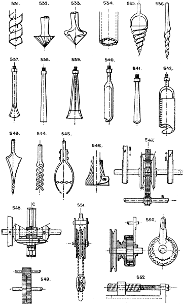
531. Twist drill for metal.
532 & 533. Countersinking drills for wood.
534. Diamond drill for rock; bores an annular hole, the core of which breaks out at intervals.
535 to 545. Well boring tools for different kinds of strata; tools for raising broken rods, &c.
546. Hollow boring cutter for cutting a shoulder on a central core; dowelling bit.
Section 31.—DIFFERENTIAL GEAR.
Devices to utilise the difference of velocity, or power, between two distinct moving parts.
547. Equational box. Two drivers A, A′, equally speeded in opposite directions, will drive the bevil gear at same velocity without revolving the spur wheel C′ which is loose on the shaft; but any alteration in the relative speeds of A and A′, causes the bevil pinion to travel round, carrying the spur wheel C′ at a speed equal to half the difference of the two velocities. This gear is used on traction engines to drive the swivelling wheels round curves, where the proportionate velocities of the wheels will vary with the radius of the curve. In this application of the gear B is the driving shaft, and A and A′ the swivelling wheels.
548. Is a modification of 547. The pinion A may be controlled in speed by any hand or automatic device, to vary the speed of the driven pinion B. The belt pulley C carries round the bevil wheel D, driving B at a speed varying with the motion given to A.
549. Two wheels (one of which has a different number of teeth to the other) gearing into one pinion; used for counters and slow motions of all kinds.
550. Is an application of No. 549 by internal or epicycloidal gear to pulley blocks. Moore’s patent (No. 1545) and Pickering’s patent are examples. The arm shown is not required where two internal loose wheels are used with different numbers of teeth, and one pinion as in No. 1545, but if used is fixed to the pinion so that it is prevented from revolving, but retains its circular swaying motion; in this case, one internal wheel is movable and the other fixed, the speed being equal to the difference in number of teeth of the loose wheel and pinion at each revolution of the eccentric shaft.
551. Weston’s differential pulley block, consisting of a two-grooved pitched chain-sheave having different numbers of teeth, in combination with a return block and endless chain.
552. Differential screws. These may be both of the same hand, or one right and one left-handed, and any fractional speed secured by proportioning the pitches.
Larger plate.
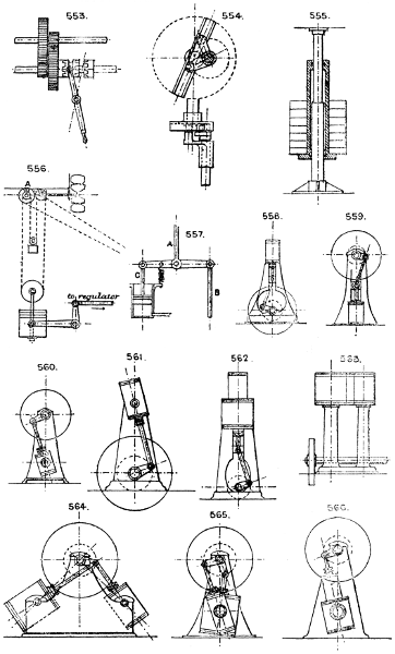
553. Two-speed gear, operated by a double clutch, which throws either pair into gear as required.
554. Stewarts’ differential gear. Two cranks, one fixed to a sleeve and the other to a centre shaft, are driven round at varying velocities by a slotted crosshead revolving with the driving shaft. The two shafts are not in the same line.
555. Differential hydraulic accumulator. The effective area of the ram is the annular shoulder, or the difference between the areas of the top and the bottom rams.
556. Differential governing device. The motive power drives A which winds up the large weight; the small weight tending to run down, drives the fan regulator, and the two weights are so adjusted that when the proper speed is attained, both weights are stationary; any change of speed causes them to run up or down, so actuating the regulation by the bell crank lever and rod.
557. Varying differential regulator. The upper rod A is connected to the regulator valve or other device, and it is capable of receiving motion from either the piston, which acts against a spring, or from the rod B attached to some positive reciprocating part, so that the nett movement of A is due to the difference of motion of B and the piston C.
Differential Worm Gear, No. 1559.
Section 32.—ENGINES (TYPES OF).
The following sketches are type drawings of the most important forms of Steam Engines in use, and are intended to afford a choice of outline arrangements from which in any scheme under consideration a selection may be made as a basis, without reference to details.
VERTICAL ENGINES.
558. Overhead cylinder engine.
559. Overhead crank engine,
560. Overhead crank engine, cylinder oscillating.
561. Overhead cylinder engine, with oscillating cylinder.
562. Overhead tandem compound engine. - These can, of course, be reversed and the crank fixed overhead.
563. Overhead double compound engine.
564. Overhead one-crank compound oscillating engine, cylinders at right angles and receiver between.
565. Overhead double-crank compound oscillating engine, with receiver.
566. Overhead crank compound tandem oscillating engine.
Larger plate.
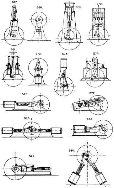
567. Vertical engine, with top guides, double connecting rods, and underneath crank shaft.
568. Vertical trunk engine.
Note that the trunk plan is applicable to any of the preceding arrangements, and is employed where a very short engine is required.
569. Vertical triple compound engine, single acting cylinders. The high pressure steam acts first on the under side of the small piston, is then expanded into the annular under side of large piston, and finally expanded into the upper side of large piston.
570. Vertical compound engine, with annular cylinder. The central cylinder is the high pressure, and the annular cylinder the low pressure.
571. Vertical annular cylinder engine, with crank below.
572. Vertical slotted crosshead engine.
573. Standard vertical engine; a type largely used and possessing many good points.
574. Double cylinder engine, with T connecting rod. (Bernay’s patent.)
HORIZONTAL ENGINES.
575. Box bed engine, high pressure. - These can, of course, be duplicated side by side.
576. Double box bed engine, coupled end to end.
577. Oscillating cylinder engine, with crosshead guides.
578. Trunk engine.
579. Return crank engine.
580. Diagonal engine. See also No. 564.
Larger plate.
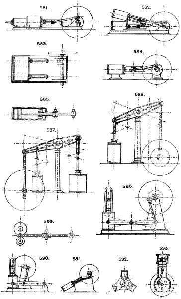
581. Horizontal tandem compound engine.
582. Galloway’s oblique compound engine.
583. Double cylinder compound engine, with receiver, cranks at right angles.
584. Trunk bed engine.
585. Double piston engine. The pistons are sometimes coupled to two crank pins at right angles.
Condensers (see Section 25) may be driven (a) from horizontal engines either direct by continuation of the piston rod, or (b) may be worked horizontally below by a vertical rocking beam coupled to the main crosshead, or (c) worked vertically below by a bell crank coupled to the main crosshead, or (d) by a separate small steam cylinder working independently, or (e) by a connecting rod or gearing from the crank shaft.
For Jet Condensers see Section 25.
BEAM ENGINES, &c.
586. Ordinary pillar and overhead beam engine.
587. Has extended beam and double cylinders, either as a compound engine or one cylinder may form a pump or blast cylinder. In some designs the high and low pressure cylinders are placed side by side and coupled to the same end of the beam by a modified parallel motion.
588. Side lever engine.
589. Plan of beam engine, with compound cylinders.
590. Walking beam engine.
591. Diagonal engine.
592. Three or four cylinder high-speed engine, with single-acting cylinders.
593. Vertical high-speed single-acting engine, with one or more cylinders.
Larger plate.
Section 33.—ENGINES AND BOILERS COMBINED (see also Boilers, Sec. 6).
VERTICAL ARRANGEMENTS.
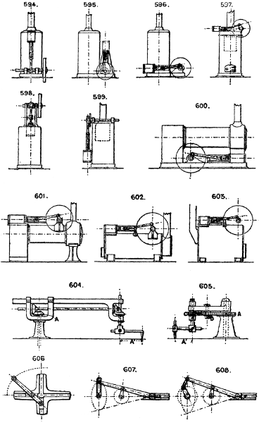
594. In this engine the boiler forms the standard for support of engine parts, but it is better to fix these on a vertical bed-plate bolted to the boiler, or as No. 595.
595. Any type of vertical engine and any type of vertical boiler can be combined on this plan.
596. Vertical boiler (any type) and horizontal engine (any type).
597. Any type of vertical boiler, with short horizontal engine on crown.
598. Vertical boiler, with cylinder sunk in the centre of crown.
599. Overhead crank engine and boiler, the latter forming the base to which the engine parts are fixed.
HORIZONTAL ENGINES.
600. Loco.-type semi-fixed horizontal engine.
601. Loco.-type semi-fixed horizontal engine, with engine on top. When placed on wheels this type constitutes the well-known “Portable.”
602. Horizontal semi-fixed boiler, with circular shell and engine on top. (See No. 72.)
603. Horizontal semi-fixed boiler, with underneath fire-box. (See No. 71.)
Section 34.—ELLIPTICAL MOTION.
604. Ellipsograph; by gearing; the bevil wheel A is fixed, the other three revolving with the whole machine on the fixed central standard, the distance A′ should equal the difference between the major and minor axes of the ellipse.
605. Performs the same operation in a similar way; A is fixed; B is same diameter as A; and C = 1⁄2 diameter of A and B.
606. Common trammel or ellipsograph.
There are other forms of apparatus for drawing ellipses merely (see Knight’s Dictionary of Mechanics). See Trammel Gear, Sec. 40.
607 & 608. Two forms of ellipsographs or elliptical cranks.
See also No. 144.
Larger plate.
Section 35.—ELASTIC WHEELS.
Wheels with rubber tyres are the common form. Wheels with a loose flat tyre outside a fixed tyre and with various forms of springs inserted between the tyres. (See Springs, Section 80.)
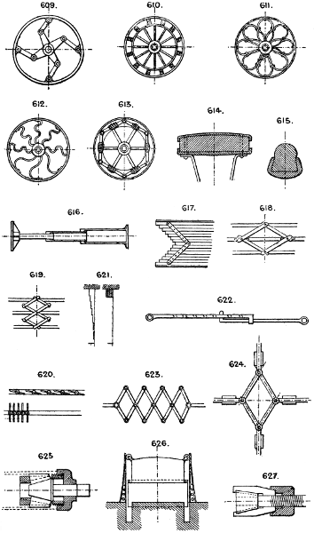
609. Huxley’s wheel, with spring tyre and jointed spokes.
610. Wheel with double tyres and intermediate springs.
611. Two plans of bent spoke, spring formation.
612. Two plans of bent spoke, spring formation.
613. Has an outer elastic tyre and an inner rigid ring, to which the tension or compression springs are fixed.
614 & 615. Sections of rubber tyres.
Wheels are also made with rubber rings applied between the boss and shaft so as to allow a limited amount of elasticity between the wheel and axle.
Section 36.—EXPANDING AND CONTRACTING DEVICES.
Common expedients for these purposes are—jointed folding rods, as a carpenter’s rule; the telescope tube; net work; diagonally crossed and jointed bars; lattice work; springs (see Section 80); lazy tongs (No. 623).
616. Telescopic ram hydraulic lift. (See also No. 1217.) Consisting of two or more rams sliding within each other.
617. Parallel bar expanding grille, or gate.
618. Parallel bar expanding grille, with lazy tongs motion, each alternate bar has slotted holes as shown.
619. Modification of 618. The number of horizontal bars can be multiplied indefinitely.
620. Venetian blind; this method is used also for movable doors or partitions, sliding horizontally.
621. Venetian blind, but without revolving motion to the laths or slats.
622. Perforated bar and hooked rod suspender.
623. Lazy tongs expanding connecting rod.
624. Four-guide expanding link device, for varying motion.
625. Thorburn’s tube expander, operated by a central cone and ring of conical rollers.
626. Gasometer.
627. Timms’ expanding boring tool. Operated by a central cone and three or more diagonal feathers, sliding in dovetail grooves in the central cone.
Expanding Mandrel, No. 507.
Expanding Chucks, Nos. 489, 491, & 506.
Larger plate.
628. Expanding basket, with chain corner suspenders.
629. Expanding socket, with sliding ring grip.
630. Expanding grating, formed of bent steel laths on edge.
631. Bridge or flap between cars, having buffers.
632. Expanding core barrel, in three parts, expanded by a wedge.
633. Expanding mandril or chuck. See also Section 28.
Expansion Joint, Nos. 1076, 1077.
Expanding Pipes, No. 1079.
Section 37.—FASTENING WHEELS TO SHAFTS.
Besides the ordinary plan of shrinking them on while hot, the following are the chief devices in use:—
634. Square shaft and single key.
635. Square shaft and two keys at right angles; two keys should always be used for a square shaft, unless it has been machined to fit to the hole.
636. Round shaft and hollow key.
637. Round shaft and flat key.
638. Round shaft and sunk key.
639. Staked fastening, four keys, usually on flats cut on shaft, but better if slightly sunk into shaft.
640. Set screw. Cannot be depended on for any but light strains.
641. Taper pin.
642. Split pin; always used where a pin, bolt, or centre is liable to work loose.
643. Cotter and slot.
644. Screwed pin through shaft and boss of wheel.
645. Octagonal shaft of cast iron, with four keys, or the four keys may be cast on shaft.
646. Cotter or pin through side of shaft.
647. Large wheels are sometimes wedged with iron and wood wedges all round on a square or octagonal shaft having feathers cast on it.
648. Set screw, tapped half into shaft and half into wheel.
649. Screwed shaft, nut and clamping plates; used for emery wheels, grindstones, circular saws, and milling cutters.
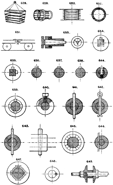
Larger plate.
650. Screwed end and nut, the hole in wheel being square, or round and fitted with key.
651. Gib head taper key.
652. Plain taper key.
653. Taper round pin.
654, 655. Split pins (round).
656. Cotter and split pin.
657. Cotter and nut.
658. Dovetail taper key, or fixing for projection, cutter or bracket.
659. Self-locking pin; cannot work out.
660. Split collar and ring fastening, sometimes used instead of a nut and screwed end; the inner ring is in halves.
661. Piston rod fastening.
662. Locking feather and wedge fastening, for rollers, &c., prevents end motion.
663. Railway chair key.
Section 38.—FRICTION GEAR.
Various forms of friction gearing are much used, the chief objection to this kind of gear being the excess of pressure on the bearings required to give sufficient grip to drive the gear.
664. The common form of flat-faced friction gear for hoisting purposes, &c. See No. 1211. The required pressure is given by a weighted lever.
665. Friction bevils, plain faces, for governor driving, &c.
666. Friction bevils, the pinion being usually of hard leather; the pressure may be applied in the direction of either of the arrows.
667. Multiple V gear. A common mistake is to run these too deep in gear; the narrower the surfaces in contact, short of the seizing or crushing point, the less the power wasted in friction.
668. A very small pinion of leather, wood, or rubber is frequently driven by a large driving wheel for obtaining high speed with steadiness, for driving dynamos, fans, &c.
669. Disc wheel and rubber pinion, arranged to reverse motion or vary speed. See No. 1595. The motion is reversed by throwing either wheel into gear with the pinion, and the speed varied at will by raising or lowering the pinion, used for screw presses.
670. Wedge friction gear.
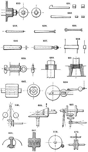
Larger plate.
671. Coupled bearings for friction gear, to allow of any required pressure or “bite,” the strains being self-contained.
See also No. 737, 738, 1294.
Section 39.—GUIDES, SLIDES, &c.
PISTON-ROD GUIDES.
672. Two bars and crosshead; these must be far enough apart to allow for the angle of the connecting rod.
673. Four bars, crosshead, and slide blocks; the connecting rod working between the two pairs of guides. The bottom guides are often cast solid with the bedplate.
674. Bar and slipper.
675. Adjustable slipper; there are other adjustments for wear by wedge pieces, similar to No. 19. See also No. 21.
A plain guide bush is sometimes used as No. 682, and a forked connecting rod with long fork coupled to the gudgeon or crosshead.
676. Section of No. 673 and alternative crosshead for two round bar guides.
677. Slide bed and slipper.
678. Section of trunk guide, cast with engine bed and bored out.
679. Oscillating cylinder piston head guides.
680. Oscillating fulcrum in lieu of guides.
681. Diagonal crosshead and guide bars, to allow the crank and connecting rod end to pass the guide bars.
VALVE ROD GUIDES.
682, 683, 684, & 685.
GUIDE ROLLERS.
686 & 687. Guide rollers for ropes, &c.
688 & 689. Guide rollers for bars of various sections.
LIFT AND HOIST GUIDES.
690. Cage guided by four corner posts.
691 & 692. Cage runs on two vertical rails, and is steadied by a third guide. For large cages. Small cages only require guides on one side, as 692.
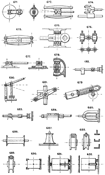
Larger plate.
693. Iron wire or rod guides, strained tight, are sometimes used, especially in mines, as guides for the cage; two are used to guide the cage and two for the balance weight.
694. Planished round iron guides, with half round fixing brackets and runners attached to cage; these guides are equal to planed bars and much less costly; two are usually sufficient for any cage.
695. T L or ⊔ iron guides, for goods lifts.
696. Wire rope guides, with separate pair of wood guides for balance weight.
697. Intermediate guides for double cage lifts; for large cages extra guides at each side should be used.
698. Sloping carriage guides.
699. Vertical bracket cage guides.
MACHINE GUIDE BEDS.
700. Double V bed, with set screw adjustments.
701. Guide bed for planing machine, or any machine where the bed is not liable to lift in working.
702. Round bar and flat guide bed.
703. Deep V guide; much used for crossheads, tool boxes, &c., requiring accurate movement.
704. Lathe bed with square guides and adjustments for wear.
705. Planing machine, double V bed.
706. Crosshead for two single bar guides, with renewable wearing strips and square guide surfaces.
707. Radial slide for tool box, usually of same section as No. 700.
ROPE GUIDES.
708, 709, & 710; in 709 the rope can be threaded without passing the end through.
Section 40.—GEARING, VARIOUS DEVICES IN (not otherwise classed).
711. Conical rotatory gear. Applied to reaping machines. See also Pan Screen, No. 1264.
712. Triangular eccentric, used to obtain a pause of one-third revolution at each end of the stroke.
713. Face plate worm gear.
714. Double rack and pinion gear.
715. Double gear wheels.
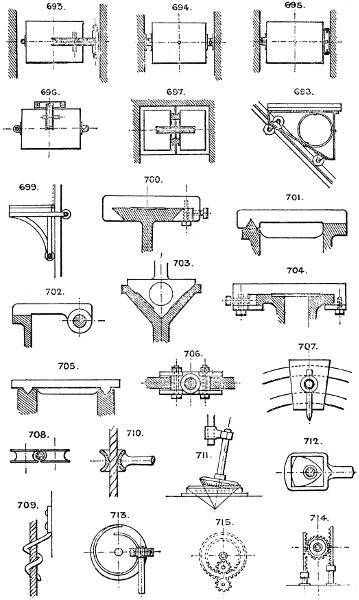
Larger plate.
716. Eccentric gearing; the wheel A being fixed on a crank pin in the driving wheel B, drives the dotted gear at a speed proportionate to the diameters of the wheels A and the driven wheel.
717 & 718. Forms of epicyclic or planet gear. Several modes of driving these may be employed by fixing one or other of the three wheels, the other two revolving. See Differential Gear, Section 31.
719. Multiple trammel gear. The pinion is half the diameter of the wheel, and makes two revolutions to one of the wheel.
720. Trammel crank gear; the crank revolves once to two double strokes of the rod.
721. Knight’s noiseless gearing, for two shafts running in opposite directions. Each shaft has two equal cranks at right angles, which are coupled by links to rocking arms, which are also coupled in pairs.
722. Eccentric variable speed toothed gear.
723. Scroll bevil gear.
724. Segment reversing gear, to obtain two speeds in portions of one revolution, and in opposite directions. See Reversing Gear, Section 74.
725. Snail wheel, or scroll ratchet.
726. Combined spur and bevil wheel.
727. Double screw gear, for steering gear, &c.
728. Angular ball-jointed crank motion.
729. Crank gearing between two shafts running in the same direction. See No. 187. The cranks should be similar to Nos. 174 or 175.
730. Snail worm gear.
731. Diagonal engine or pump, with bevil gear revolving motion and three or more cylinders.
732. Angle coupling on Dr. Hooke’s principle. See No. 292.
733. Worm and crown gear. Used in chaff machines; useful to obtain a slow feed on two shafts in opposite directions.
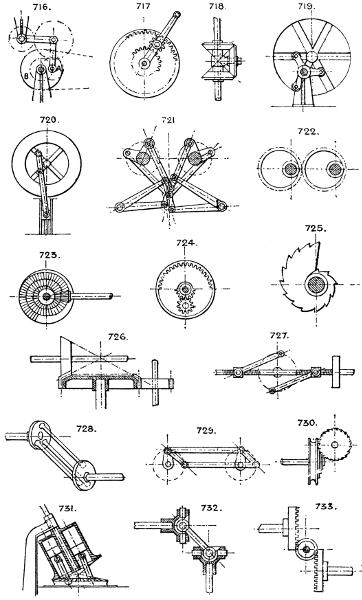
Larger plate.
734. Ball wheel, with limited angular traverse gearing into one or two pinions.
735. Scroll and rack.
736. Variable speed gear, from an elliptical or other irregular-shaped driving wheel, combined with a tied idle intermediate wheel.
737. Spring friction grip wheels.
738. Intermittent reversible feed motion. The pinion is of leather, and drives the segment till it runs out of gear; when the machine is reversed it travels an equal distance the opposite way.
Section 41.—GOVERNING AND REGULATING SPEED, POWER, &c.
739. Is a device for varying the opening of a main valve (connected to rod A) by the pressure on the small piston, which moves it against the tension of a spring.
740, 741, 742, & 743. Types of centrifugal governors, of which numerous varieties are in use.
Pumping engines may be governed by allowing the pressure of water in the rising main to accumulate in a stand pipe or equivalent device until it stops the engine by excess of pressure. To prevent such an engine running away a catch is used, kept open by the pressure of water; when the pressure falls below a certain point the catch is released and closes the throttle valve.
Steam engines may also be safeguarded in the same way by a catch which is released and closes the throttle valve when the governor becomes fully expanded.
744. Screw and nut device, to control the travel of any machine, such as a lift, by reversing the belt or throwing out a catch after any specified number of revolutions, the travel being adjusted by the stop nuts.
745. The cataract is one of the oldest governing devices. It consists essentially of a vessel which is filled with water by one stroke of the engine, and empties itself through an adjustable orifice during the return stroke, the valve motion being prevented from reversing till the water is all discharged.
746. Gas engine governor. Rod A has a reciprocating motion from the engine, and the spur on lever B strikes the end of the gas valve slide when brought in line with it by the motion of the governor, thus supplying gas only when the governor falls to a certain point.
Differential Governor. See Nos. 556 and 557.
Section 42.—HYDRAULIC MULTIPLYING GEAR.
747. Is the ordinary “chain and sheave” multiplying gear, unequally geared, thus—
Ram end. Cylinder end.
With 1 sheave 1 sheave it is geared 3 to 1. &c.
„ 2 „ 2 „ „ 5 to 1.
„ 3 „ 3 „ „ 7 to 1;
748. Is the same plan, but equally geared—
Ram end. Cylinder end.
With 1 sheave No sheaves it is geared 2 to 1. &c.
„ 2 „ 1 sheave „ 4 to 1.
„ 3 „ 2 „ „ 6 to 1;
749. An arrangement of the sheaves suitable for vertical working, geared 8 to 1.
750. An arrangement of the sheaves suitable for vertical working, but geared 6 to 1.
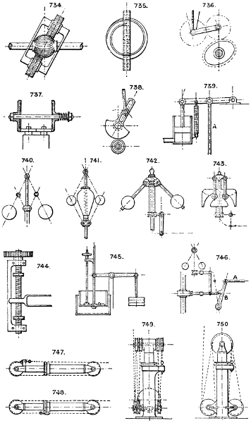
Larger plate.
751. An arrangement of the sheaves suitable for vertical working, but geared 4 to 1.
752. Stevens and Major’s patent for horizontal working. The angle of the chain helps to support the weight of the ram.
753. Modification of 752, sometimes used, and suitable for both horizontal and vertical positions, with any required multiplication of speed.
754. Rack gear; short stroke piston cylinder plan.
755. Double rope vertical ram gear.
756. Arrangement with the sheaves all at head of cylinder.
For Telescopic Hydraulic Lift, see Nos. 1217 & 616.
Hydraulic Balance gear, Nos. 371, 373.
Section 43.—HOOKS, SWIVELS, &c.
For Chains and Links, see Section 11.
757. Double or match hook.
758. Split link. See also the common Key Ring.
759. Self-locking hook, with inclined shoulder and pin.
760. The common “Lewis.”
761. Self-gripping claw grab. See also 516, 505.
762. Grab bucket, on same principle.
763, 764, & 765. Double S links.
766. Hook with rope grip.
767. Snap hook.
768. Snap link.
769. Slip hook for a monkey or pile engine; a rope is attached to the eye in end of lever which pulls the loop link away from the bottom link to which the “monkey” is suspended, allowing it to fall.
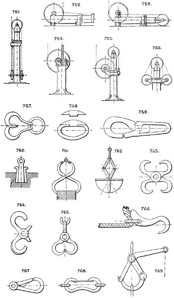
Larger plate.
770. Automatic slip hook; slips the T end of the “monkey” by the curved arms striking the sides of a fixed stop hole.
771. Draw bar hook, self-locking.
772. Fixed bar hook, with snap.
773. Slip hook.
774. Hook, with mousing ring; slip hook.
775. Crane hook, with swivel.
776. Double swivel links, inserted in a chain to take out the twist.
777. Triangular link, to attach two chains to one.
778. Safety link. Has a flat on link to slip in notch of hook.
779. S link.
780. Split link.
781. Bolt shackle.
782. Double link and bolt connection for ordinary chain.
783. Pin shackle.
Section 44.—INDICATING SPEEDS, &c.
784 & 785. Hand (portable) indicator, to indicate speed of revolution of a shaft, &c., by simple wheel work and dial plate.
786. Governor gauge, indicates the speed by the angle of the balls moving a finger on a vertical scale.
787. Steam engine indicator, of which there are many varieties. Macnaught’s, Richards’, Darke’s, Kraft’s, Casartelli’s, &c., are examples, in which a small steam piston operates a marking point by the varying pressure of steam acting against a spring; the paper is usually coiled on a cylinder having a reciprocating motion by a string from the engine.
788. Morin’s dynamometer. Consists of two belt pulleys connected by a spring; one receives the strain of driving belt, and the other transmits it, the spring indicating the tension on the belts.
789. Regnier’s dynamometer indicates the tension on the connections by contraction of the spring operating a dial plate.
790. Bourdon tube pressure indicator. The tube is of flat section, and its curved portion expands with the pressure, operating a finger on the dial by rackwork.
791. Worm gear and dial to register the number of revolutions. See No. 1559.
Other forms of pressure gauges are—1st. The mercurial gauge, in which the pressure is indicated by the height of a column of mercury in a glass tube. 2nd. The water gauge, in which a column of water replaces the mercury. 3rd. The spring balance (see No. 1729). See also Nos. 1730, 1728.
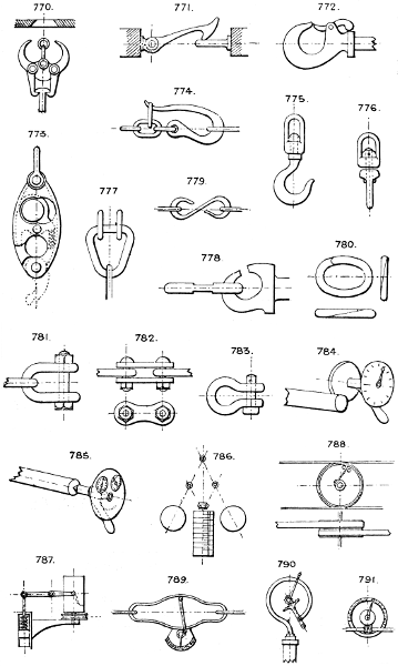
Larger plate.
792 & 793. Winding engines are provided with indicators on the principle of No. 744. The travelling nut has a pointer whose position on a vertical graduated scale shows the position of the cage in the pit.
Vertical scale indicators are also employed to show the level of water in tanks, reservoirs, &c. See No. 1730.
Water tube indicators are employed to show the level of water in boilers, &c., as also gauge cocks fixed at various heights in the boiler.
Section 45.—JETS, NOZZLES, AND INJECTORS.
794. Straight jet, for long distances.
795. Short jet.
796. Rose jet, for spreading.
797. Fan jet, or spreader.
798. Blast tuyere.
799. Smith’s tuyere and water bosh.
800. Jet aspirator, for inducing a mixed current of air and water or steam.
801. Steam jet pump; the steam enters by the central jet and causes a vacuum, into which the water rises by the branch pipe.
802. Insufflator for steam and air blast; used also as a petroleum injector, &c.
803 & 805. Spray jets; the liquid rises by gravity at the small vertical nozzles, and is driven in a spray or mist by a cross blast of air from the horizontal jets.
804. Injector. The varieties of this contrivance are too numerous to specify. See Graham’s, Gifford’s, Hall’s, Hancock’s, and others in common use.
806. Plain or spreading jet. The eight vanes can be pushed into the jet of water to cut it up by moving the sliding ring.
807. Ventilating jet or aspirator, with several lateral openings for inducing a current.
Jet condensers. See Section 25.
Section 46.—JOURNALS, BEARINGS, PIVOTS, &c.
See also Section 70.
808. Plain or solid pedestal.
809. Half bearing, sometimes used without a cotter.
810. Half bushed bearing, having a half brass on the lower side only.
811. Chambered long bearing.
812. The ordinary double brassed pedestal or plummer block; sometimes made with the cap and joint of brasses at an angle of 45° when the shaft is subject to horizontal thrust. Numerous modifications of this bearing exist.
813. Slot bearing for rising and falling spindle.
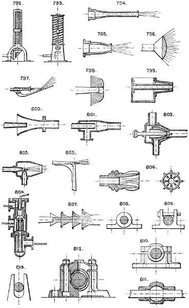
Larger plate.
814 & 815. End thrust bearings.
816. Sliding bearing, with vertical or horizontal traverse.
817. Double V bearing to accommodate different sizes of shafts.
818. Vertical shaft footstep.
819. Vertical pivot.
820. Horizontal pivot and set screw; the screw should have a lock nut to prevent it being worked back by the motion of the spindle.
821. Conical neck, usually with steel bush.
822. Spherical footstep, to allow the shaft to sway out of the perpendicular.
823. Horizontal bearing, allowing the shaft to run out of line.
824. Balanced bearing, to bear the weight of a light shaft, and placed between the fixed bearings.
825. Self-adjusting bearing for line shafts, with ball and socket movement.
826. Ball and socket bearing for vertical spindle, allowing considerable variation from a right line.
827. Horizontal thrust bearing, with multiple flanges and double brasses, each capable of separate adjustment; used for screw shafts in steam-ships.
828. A form of pedestal, with the cap provided with end joggles to prevent looseness.
829. Trunnion bearing, for oscillating cylinders, &c. The steam is conveyed through the bearing, which has a stuffing box and gland to prevent leakage.
830 & 832. Swinging support for a shaft, having a sliding bevil gear or other motion upon it which has to pass the swinging support; used for lathe sliding gear, overhead travellers, &c.
831. Ball and socket centre for car bogies, &c.
833. Pedestal with side adjustment for the brasses by taper keys and screw adjustments.
Bearings running under water are generally lined with strips of lignum vitæ and require no lubricant.
So-called self-lubricator bearings are in use, lined with strips of patent composition metal.
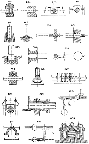
Larger plate.
834. Centre bearing, with annular grip, for a heavy centre piece or car bogie.
835. Centre bearing, with allowance for some amount of oscillation.
Coupled bearings. No. 671.
Section 47.—PLATE WORK.
836. Single riveted lap joint.
837. Double riveted lap joint.
838. Single riveted butt joint.
839. Double butt joint.
840. T-iron butt joint.
841, 842, 843, & 844. Angle or edge seams.
845. Transverse tubular seam.
846, 847, & 848. Reducing ring seams.
849, 850, 851, & 852. Bottom seams round water spaces, fire-boxes, &c.
853. Expansion hoop joint in boiler flues, &c.
854 & 855. Fire-box stays.
856. Gusset stay for flat ends.
Flat bar, tube, and round iron stays are also much used to stay flat surfaces in boilers and tanks.
In household boilers it is usual to weld all the seams, thus avoiding L iron and other riveted work. See Nos. 89 to 96.
Flue tubes in boilers are stayed also by cross tubes inserted at intervals, such as Galloway’s patent conical cross tubes.
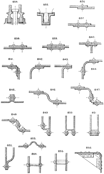
Larger plate.
857 & 858. Cover plates to carry tensile strains over joints in plates, L irons, &c.
859, 860, 861, 862, & 863. Various forms of joints employed in plate iron structures, boxes, tanks, &c., not subject to much strain. 863 is a dovetailed joint.
864. T or L iron strut end joint.
865. Junction of flat bar and diagonal T or L iron.
866. Gusset plate joint for diagonal ties and struts.
867. Mode of jointing boiler plate corners by tapering the corners of the plates.
868. Another form of angle joint.
Section 48.—LEVERS.
Levers are of three orders (see Section 53). The fulcrum or rocking centre may be at either end or at some intermediate point. In practice the fulcra are usually shafts or pins (see Sections 76 and 77), and the following are the typical forms in use.
869, 870, 871, & 872. Elevation and plans of plain levers, with end bosses for rod attachments.
873. Plan of plain lever, with forked end.
874 & 875. Bell crank levers, with plain or forked ends.
876. T or double cranked lever.
877. Forked end, off-set.
878. Fish bellied lever of the 2nd order.
879. Balance weight lever.
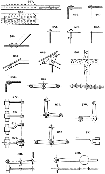
Larger plate.
880. Hand lever, with round handle.
881. Hand lever, with flat handle.
882. Another form of round handle sometimes used.
883. Crank handle.
884. Starting lever, with spring catch.
885. Another pattern of ditto.
886. Similar lever, with side or crank handles.
887. Foot lever.
888. Foot treadle frame.
889. Wrist plate or T lever.
890. Hand lever, adjustable as to length by means of a slot and locking bolt. For this purpose a plain round rod passed through a central socket and fixed at any radial length by a set screw, is often used; or the hand rod may be cranked as No. 1784.