PART I. SECTIONS 1-106. (continued 2)
Reading edition
891. Double hand lever.
892. Lever, formed of two wrought iron or steel plates and distance pieces.
893 & 894. Rocking levers, with sliding swivel joints.
895. Forked lever, to span a central bearing.
896. Hand lever, simple pattern; wrench or spanner.
897. Headed lever, for valve rod and other movements. See Nos. 149 to 152.
See also Section 97.
Section 49.—LOCKING DEVICES.
898. Common sliding bolt.
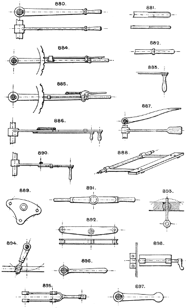
Larger plate.
899. Common latch.
900. Cam locking bolt; locks the bolt when either in or out, so that it can only be moved by the cam spindle.
901. Crank movement locking bolt, similar to the last.
902. Bolt of common lock.
903. Disc and pin.
904. Side pawl.
905. Locking pawl.
For Pawl and Ratchet Gear see Section 62.
906. Spring catch, with round end which slips past the socket if sufficient force is applied, used for swing doors, &c.
907. Another form, bevilled on one side.
908. Hook latch.
909 & 910. Hasp and staple.
911. Crossbar and hooks.
912. Hand set screw.
913. Drop catch for turntable, &c.
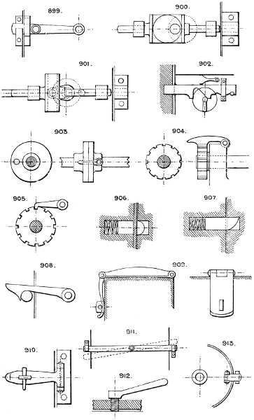
Larger plate.
914. Turning or twisting bolt.
915. Rope or rod stopper, with cam lever grip. See No. 47.
916. Chain stop.
917 & 918. Spindle grips, to lock a sliding or revolving spindle in a bearing or bush.
919. Clamp and screw.
920. Sliding shaft locking pin; used for lathe headstock back-gear shafts, &c.
921. Lever locking hook; the lever is hinged so that it can be slipped over the hook.
922. Bow catch for ladles, skips, &c.
923. Segment-slot and bolt fixing for swivelling base.
924. Pin lock for turntable or disc.
925. T catch.
926. Roller and incline slot for locking a rod or rope.
927. Revolving bush lock for catch rod; the catch rod can only slip through the bush when the latter is in one position (see plan view).
928. Wire fencing notches in L or ⊔ iron.
929. Trap door automatic catch.
930. Screw and bridle suspension, for blast pipes, &c.
931. Drop loop fastening for a door.
932. Spring stud lock.
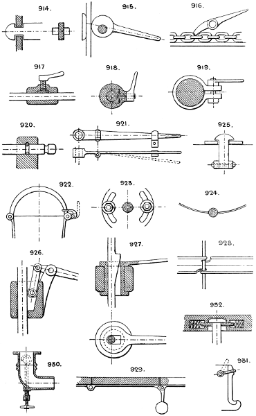
Larger plate.
933. Disc and radial slot; the rod can be slipped out sideways when the disc is turned so as to bring the slots together.
934. Radial hinged lever and crown ratchet.
935. Locking bar to fix a lever in any position.
936. Pawl for locking sliding shaft, used for winches, &c., having double and single purchase gear or shifting clutches.
937. Fastening eye bolt for a hinged cover; the bolt is also hinged, and can be turned down out of the way. See also No. 1930.
938. Crank arm device, to lock a valve or lever in two positions. See also No. 16.
939. Gun, breech-loading, sliding cylindrical block locked by turning the arm into a notch.
940. Door fastening staple and cotter.
941. Common cotter.
942. Half nut locking and unlocking device, used for lathe leading screws; the half nuts are moved simultaneously in opposite directions by cams on the lever spindle.
943. Swinging catch to secure end of a drop bar.
944. Tool post, to swivel and lock in any position. See also No. 493.
945. Locking screw, to lock the hand wheel and spur pinion to the shaft when required to be driven by it.
See also Lock Nuts. The common varieties of lever locks with stepped key-wards.
See No. 1723.
Section 50.—HINGES AND JOINTS.
946. The common double-leaf hinge.
947. Rising hinge, to cause the door to lift slightly as it opens, it will then close of itself without a spring.
948. Cup and ball hinge.
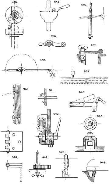
Larger plate.
949 & 950. Pintle hinges.
951 & 952. Parchment or leather hinging for wood movements.
953. Dovetail joint, used on iron bedsteads, &c.; the circular dovetail is slightly tapered and fitted tight.
954. Hinge for a door, required to lay flat against the wall at either side when open.
955. Hinge pin for rocking levers on a knife edge.
956. Door spring hinge, to return the door always to its central position; the cams press against a roller attached to the springs.
957. Another method, with tension springs.
958. Rocking bearing or knife edge, used for weighing machines, &c.
959. Knuckle joint, halved together; the bolt secures the two parts together.
960. Door spring hinge with open springs and toggle movement.
961. Gate hinges, with double pintle at bottom to cause the gate to return to the central position without springs.
962. Link hinge, for a grid or trap door, to allow it to lie flat when opened.
963. Bayonet joint. A common device.
964. Double scarfed and joggled joint, for pump, rods, &c., with ferrules and keys to tighten up.
965. Universal joint. See Dr. Hooke’s Joint, Nos. 33 and 34.
966. Knuckle jointed levers.
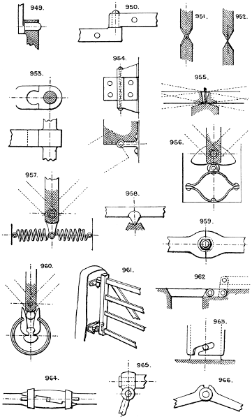
Larger plate.
967. The common male and female or nipple and socket rod joint.
968. Multiple hinges, with one centre bolt, for long or heavy doors.
969. Scarfed rod or bar joint.
970. Another form of hinge, to effect the same object as No. 954.
See also Swivel Joints, Nos. 893 and 894. Sections 49, 4, and 48.
Section 51.—LUBRICATORS.
I do not propose to attempt to illustrate the vast tribe of “greasers” of all kinds. They would easily fill a moderate volume, but scarcely repay the reader for perusal. I shall content myself here as elsewhere by indicating the types of most interest and importance to the machine draughtsman.
Besides the simple cup or enlarged oil hole, oil box, and grease cup, the following are the most commonly employed:—
971. Oil pan for gearing, worms, wheels, &c.
972. Revolving wire lubricator; carries a drop of oil on to the shaft at each revolution.
973. Roller and pan lubricator. Can be employed also for gum, paste, paint, &c.
974. Screw ram lubricator, to force lubricant into a cylinder or pipe against pressure, with non-return valve.
975. Telescopic tube lubricating device, for reciprocating or revolving joints, such as crank pins.
976. Another tubular device for crank pins; a hollow cup on end of a tube stands opposite the centre of the shaft, and can be fed with oil while revolving, the oil running down the tube during the lower half revolution.
977. Stauffer’s lubricator for thick oil, which is forced in by screwing down the cap.
978. Shaft bearing lubricator by the capillary action of pieces of cane, the lower ends of which dip into the oil cistern.
979. Endless string lubricator.
980. Single cock lubricator, with screwed cap for filling.
981. Double cock lubricator.
982. Hollow plug cock.
The last three are used to feed oil against steam pressure.
983. Lieuvain’s needle lubricator. A loose wire (one end of which touches the revolving shaft and the other is in the oil); keeps the oil flowing as long as the shaft is running.
984. The pressure of steam enters the cup above the oil, which is fed through an adjustable small valve at bottom.
985. Plunger or ram and cylinder lubricator, with ratchet feed worked from some reciprocating part of engine.
Lubricating or inking rollers to evenly cover a flat surface are placed at an angle of about 10° to the direction of motion of the surface to be lubricated or inked.
Large engines are fitted with an oil reservoir, and pipes are led to all joints, bearings, &c., with small cocks for regulation.
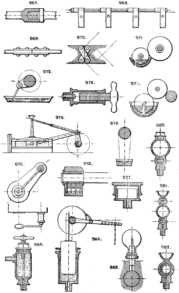
Larger plate.
Section 52.—LEVELLING AND PLUMBING.
The common spirit level and plumbline are ordinarily employed, as also the surveyor’s telescope and spirit level or “Dumpy.”
986. Gravitation level.
987. Plumbline and square.
988. Water tube level; the tube may be carried a long distance and round corners, &c., in any direction below the water level.
989. Spirit level plumbing square.
Section 53.—MECHANICAL POWERS. APPLIANCES TO VARY POWER AND SPEED.
990. Lever of the 1st order - See Applications, Section 48.
991. Lever of the 2nd order
992. Lever of the 3rd order
993. Wheel and axle; power gained and speed reduced in proportion to the diameters of the two sheaves.
994. Return block; power multiplied 2 to 1.
995. Two double sheave blocks; power multiplied 4 to 1.
996. Four single blocks; power same as No. 995.
997. Three return blocks; power multiplied 8 to 1.
See Applications, Section 42.
The inclined plane is simply a modification of the force of gravity, which acts vertically.
The wedge. See Section 37.
The screw is simply a circular inclined plane. See Section 78.
See also Gearing, Sections 40 and 84.
Section 54.—MIXING AND INCORPORATING.
998. Kneading mill, with spiral vanes.
999. Pug mill, with radial spiral paddles revolving inside a conical case.
1000. Pug mill, with spiral paddles.
1001. Pan mixer. A cylindrical case or pan with a set of arms revolving with the central shaft.
1002. Egg beater or mixing machine. Two sets of open radial frames revolve in opposite directions, the frames being shaped to pass through each other, and are driven by mitre gear driving a shaft and sleeve.
1003. Diagonal mixing barrel, with revolving and fixed vanes.
1004. Conical mixing barrel of similar construction.
1005. Diagonal mixing pan, used for confectionery, &c.
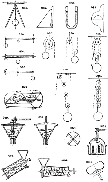
Larger plate.
1006. Mixer, with two pairs of arms running in opposite directions.
See Cross section.
1007. A modification of the last; the centres of the arms being above one another so that the arms pass each other in revolving.
1008. Horizontal table mixing machine. The stuff works its way from the centre to the edge of the table by centrifugal force.
See also No. 60. Anderson’s patent employs this plan to continuously distribute purifying material through water with which the revolving drum is charged.
See Section 13. Crushing, grinding, &c.
Section 55.—PARALLEL MOTIONS.
Purpose: to maintain rectilinear motion of a rod or equivalent detail coupled to a lever without employing guide bars.
1009. Watt’s parallel motion for a beam engine.
1010. Rack and segment motion.
1011. Epicycloidal parallel motion. The pinion is one-half the diameter of the wheel at the pitch lines, and the gudgeon is fixed upon the pitch line of the pinion.
1012. Peaucellier’s parallel motion. A is a fixed centre; B (for parallel motion) must be one-half way to C; power is applied to C; D parallel centre gudgeon.
1013. Beam, with rocking fulcrum. A A are equal, as also B B.
1014. Single radius bar and link; the radius bar to be same length as the half beam and the link hinged on its centre.
1015. All the radius bars to be of same length as the half beam.
1016. Two equal radius bars connected by a link, the main gudgeon in its centre.
1017. Beam of the 2nd order with rocking fulcrum, A and A being equal.
1018. Sector and rack motion.
See also No. 714.
Section 56.—PUMPING AND RAISING WATER.
Some of the most primitive methods are still in use, and may possibly still be found of service in particular cases.
1019. Scoop wheel.
1020. Dipping trough.
1021. Endless chain of buckets.
1022. Archimedean screw; a spiral pipe serves the same purpose as the worm revolving in a cylindrical case.
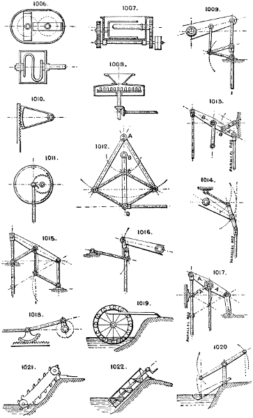
Larger plate.
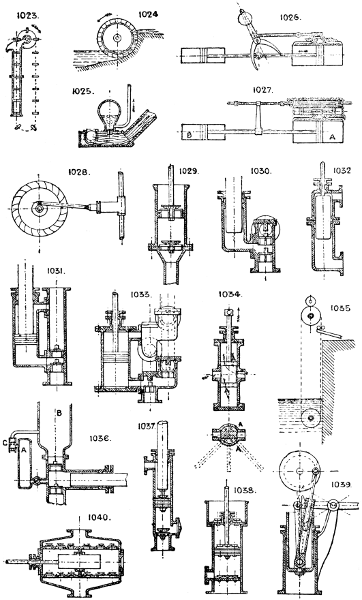
1023. Chain pump, frequently used still. The lower length of pipe should be bored to fit the buckets on chain; the rest of the pipe may be a little larger in diameter and not bored.
1024. Lifting wheel for raising water.
The following four examples are machines for raising water to any height by employing a fall of water of comparative low pressure:—
1025. Hydraulic ram. A stream of water runs down the incline pipe and flows away at the ball valve; when its speed reaches a certain point it suddenly closes the ball valve, and the shock opens the delivery valve, water flows into the air vessel till the power of the stream is checked, when the delivery valve closes, the ball drops, and the action is repeated.
1026. The Robinet. Direct-action water pressure self-acting pump; performs the same work as the hydraulic ram, that is by using a low fall and large quantity of water it raises a smaller quantity to a greater height, the low-pressure water acting on the large double-acting piston. The valve is reversed by the motion of the engine.
1027. Hydraulic pumping engine. A modification of the Robinet. A is the driving cylinder, B the pump. The main slide valve is worked by two pistons, and the pressure water distributed by an auxiliary four-way cock or small slide valve, connected to a stop rod from the main crosshead. See also No. 1741. See Sec. 93.
1028. Water wheel and pump.
1029. Single-acting bucket or suction pump.
1030. Single-acting ram force pump. Sometimes an open top cylinder and piston are used instead of a ram, as No. 1029.
1031. Double-acting ram and piston pump. Forces on both strokes; sucks only on the up stroke.
1032. Double-acting plunger or ram pump, externally packed; a favourite arrangement.
1033. Double-acting piston pump, four valves. This is of course a type of a very great variety of pumps.
1034. Double-action piston pump, without valves. The piston has an oscillating or radial motion (see plan), as well as an up and down motion, so that the two ports are alternately open to the upper and under side of piston by the small passages A A. The required motion can be obtained from No. 406, crank motion.
1035. Rope pump. A simple endless soft or porous rope absorbs water at its lower part (immersed), which water is pressed out of it between the rollers at top.
1036. Apparatus to supply air to air vessels. The main pump at every stroke draws a small quantity of water from the small air vessel A, and on the return stroke forces an equal quantity of air from the smaller to the larger vessel B. C is a double air valve.
1037. Combined bucket and plunger pump draws on the up stroke only, but delivers on both strokes.
1038. Air pump, with foot and head valves.
1039. Hand or power pump. Can be thrown into action from the crank shaft by fastening the set screw, or may be worked independently by the hand lever.
1040. “Worthington” pattern of plunger pump, double acting.
Larger plate.
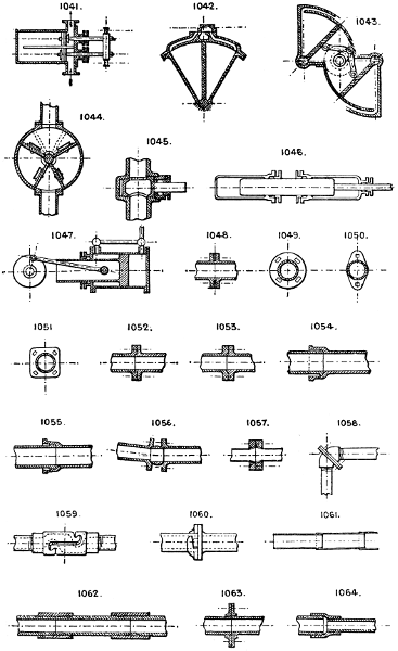
1041. Double barrel pump, with bucket pistons. The water passes both pistons, which are fitted with valves opening opposite ways.
1042. Oscillating sector or quadrant pump, with one vane or piston.
1043. Double quadrant pump. The two vanes are worked by links from a single crank.
1044. Oscillating pump, with two radial vanes keyed to a central rocking shaft.
1045. Hollow plug; oil or water feeder.
1046. Double ram pump.
Rising mains in mines and wells have been used as the main pump rods in some instances.
In pumping up to a tank or reservoir from which a down service pipe is taken, the pump can be arranged to deliver into this pipe at its nearest convenient point, instead of having a second pipe from the pump to the tank.
1047. Schmid’s trunk cyl. hydraulic pumping engine utilises a low-pressure supply to force from the annular side of the piston a high-pressure service.
See also rotary engines and pumps, Section 75.
Pumping engines, Section 61.
Section 57.—PIPES AND CONVEYORS.
Plain tubing may be either of iron, brass, zinc, lead, tin plate, sheet iron, papier mâché, indiarubber, guttapercha, leather, cotton, or canvas.
Flexible sorts of the last five materials named are strengthened when required by spiral wire, either inside or outside or imbedded in the material; also, in the case of rubber, by canvas insertion; or by being payed with yarn or wire, either wound or plaited round the exterior.
CAST IRON PIPES.
1048 to 1053. Show sections and elevations of forms of flanges employed. 1053 has a small V space, in which is inserted a ring of guttapercha cord or soft lead. Used for heavy pressures.
1054. Socket and spigot pipes.
The ordinary earthenware socket drain pipes, flue pipes, &c., are examples.
1055. Socket and spigot pipes, with tapered, bored, and turned joint.
1056. Cup and ball joint for uneven ground, &c.
1057. Wrought iron pipes, with cast iron flanges.
1058. Diagonal universal joint. See No. 1078.
1059. Swivelling joint. Coupling quickly opened or closed, faced with rubber or leather.
1060. Bayonet joint, for hydrants, &c. See No. 963.
WROUGHT IRON PIPES.
1061. Sheet iron flue pipes.
1062. Wrought iron pipe and screwed couplings.
1063. Wrought iron flange coupling.
1064. Reducing socket or coupling.
Larger plate.
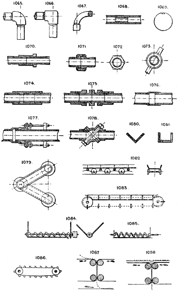
1065 & 1066. Elbows.
1067. Bend.
1068. Internal coupling for handrailing, &c.
1069. Patent lap-folded pipe.
1070. Long screw, coupling and back nut, for making the last joint in a series of pipes when the last piece cannot be screwed into both joints.
1071 to 1073. Screwed unions. The nut may be as No. 1072 or 1073.
See also Section 78.
1074 & 1075. Unions with right and left-hand threads.
1076. Expansion joint plain.
1077. Expansion joint with gland and safety bolt to prevent the joint blowing out.
A bent U-shaped tube of copper is sometimes used as an expansion piece in a line of hot piping.
1078. Royle’s patent diagonal universal joint, by swivelling the diagonal joint the pipes can be set at any angle from 0° to 90° to each other.
1079. Expanding pipes with stuffing boxes at each joint, used for conveying water, steam, or air to a movable engine or machine.
CONVEYORS.
1080 & 1081. Wood troughs sometimes lined with metal.
For conveying materials other than liquids, such as sand, coal, grain, &c., the following contrivances are used:—
Endless bands of canvas, rubber, leather, &c., sometimes with flanges like 1082.
Sloping wooden tubes or shoots.
1082. Sectional conveyor, endless, carried round pulleys like No. 1083.
1083. Creeper, an endless chain of boards or buckets sliding along a fixed wood trough. See Ewart’s patent detachable drive chain, which is fitted with special links for attachment of boards or buckets.
1084. Worm and trough, similar in principle to an archimedean screw.
See No. 1022.
Elevators for vertical or sloping conveyance usually consist of an endless band of some flexible material or chain with a number of tin or metal buckets attached at regular intervals (as No. 1086) like a creeper, No. 1083, but working in an enclosed tube.
Pneumatic tubes. See Section 19. Valves for do., No. 1638.
1085. Is an improved form of worm having no centre shaft. “Patent Anti-Friction Conveyor.”
1086. Elevator, or band and buckets, may be run in any position.
1087 & 1088. Endless web and roller devices for conveying sheets of paper, for printing or folding.
See also Raising and Lowering, Section 69.
Larger plate.
Section 58.—PACKINGS, JOINTS, STUFFING BOXES, &c.
PISTONS.
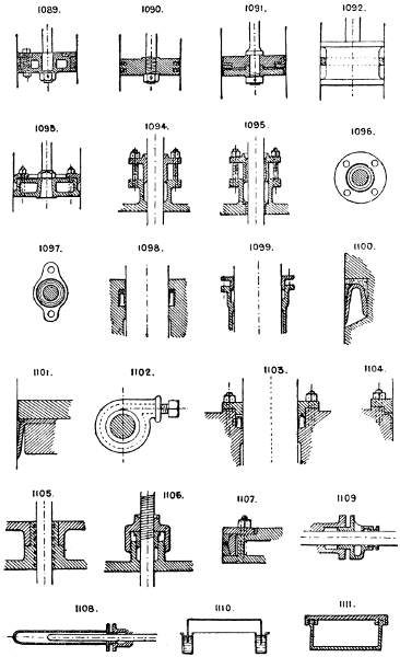
1089. Piston with junk ring; the packing is sometimes cast iron, steel, brass, or phosphor bronze rings, or even hemp or asbestos.
1090. Small pistons have generally two rings of steel or brass sprung into the grooves.
1091. Double-acting hydraulic piston for cold water; if single acting, one leather only is required; for hot water, rings are generally employed.
1092. Indiarubber rolling ring packing, used on Kennedy’s patent piston water meters.
1093. Piston, with junk ring for fibrous packing.
Numerous patents are in use for springs of various kinds applied to piston rings. See Section 80.
STUFFING BOXES, &c.
1094, 1095, 1096, & 1097. Sections and plans of gland stuffing boxes.
1098. Leather packing ring or collar, used generally for higher pressures up to 3 or 4 tons per square inch.
1099. Stuffing box for hydraulic rams, up to pressures of about 1000 lbs. per square inch, with special hard packing.
1100 & 1101. When the wear on an hydraulic leather is considerable a guard-ring should be added, as shown here.
1102. Stannah’s patent stuffing box; the packing is tightened by a set screw.
1103 & 1104. Ram leathers, with gland to facilitate renewing.
1105. Grooved steam packing. It is said that the steam will not readily pass a series of grooves round a piston rod.
1106. Useful form of gland for a screwed spindle, the thread being cut in the outer cap.
1107. V-ring piston packing rings. The inner spring ring presses the outer rings out against the cylinder.
1108. “Bottle” gland to cover a reciprocating rod end.
1109. Gland with oil space to keep the rod lubricated.
1110. Water lute or seal for gas holders, &c.
1111. Grooved joint for packing round covers, &c.
Larger plate.
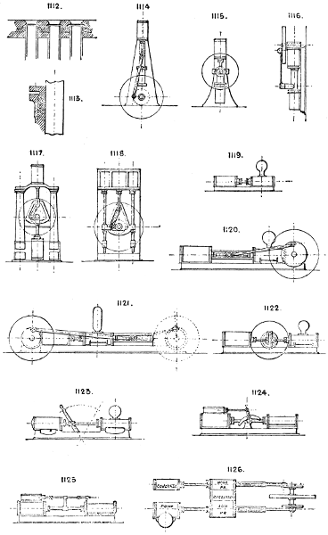
1112. Indiarubber sheet joint for the tubes of condensers, the rubber being pressed around the tube joints by a plate with projecting rings. See Plate, page 139.
1113. V-ring metallic gland packing. See Plate, page 139.
Joints of plane surfaces are usually made with red-lead for steam and water; asbestos, millboard, and sometimes rubber insertion, tape, paper, or wire gauze for steam, water, air, &c.
Section 59.—PROPULSION.
(See also Sections 60, and 12.)
On land, vehicles, &c., may be propelled by:
a.
Any engine having contained in itself its source of power; such as a steam engine, compressed-air engine, electric motor, &c.
b.
Any fixed source of power, the moving vehicle being connected to it by: 1, a rope or chain; 2, a tube; 3, an electric wire or other electric connection.
c.
By gravitation down an inclined or vertical road. See Section 69.
d.
By wind power, using sails or windmill. See Section 95.
e.
Animal power.
a. Any engine having contained in itself its source of power; such as a steam engine, compressed-air engine, electric motor, &c.
b. Any fixed source of power, the moving vehicle being connected to it by: 1, a rope or chain; 2, a tube; 3, an electric wire or other electric connection.
c. By gravitation down an inclined or vertical road. See Section 69.
d. By wind power, using sails or windmill. See Section 95.
e. Animal power.
On water, vessels are propelled by:
a.
Wind.
b.
Steam or other heat engine.
c.
Wave motion.
d.
Natural currents, tides.
e.
Animal power.
a. Wind.
b. Steam or other heat engine.
c. Wave motion.
d. Natural currents, tides.
e. Animal power.
In air, balloons have been propelled by:
a.
Wind.
b.
Some kind of engine power.
c.
Hand power.
a. Wind.
b. Some kind of engine power.
c. Hand power.
But the two latter sources must be at present considered almost impracticable.
MEANS EMPLOYED FOR PROPULSION.
On land:
a.
Steam or other engine and boiler on the moving vehicle.
b.
A reservoir of compressed air or gas, driving an engine on the vehicle.
c.
An electric battery or accumulator, driving an engine on the vehicle.
d.
Rope railway: the rope may be driven by any kind of engine.
e.
Endless rope transmission. See Section 66.
f.
Inclined or vertical hoists. See Section 69.
g.
Ice vessels, or yachts, propelled by wind and sails, windmills, &c. See Section 95.
h.
Velocipedes of all kinds, hand power lifts and hoists. See Section 69.
a. Steam or other engine and boiler on the moving vehicle.
b. A reservoir of compressed air or gas, driving an engine on the vehicle.
c. An electric battery or accumulator, driving an engine on the vehicle.
d. Rope railway: the rope may be driven by any kind of engine.
e. Endless rope transmission. See Section 66.
f. Inclined or vertical hoists. See Section 69.
g. Ice vessels, or yachts, propelled by wind and sails, windmills, &c. See Section 95.
h. Velocipedes of all kinds, hand power lifts and hoists. See Section 69.
On water, vessels are propelled by:
a.
Sails.
b.
Steamships, by screw, paddle-wheel, stern wheel, water jet, and steam jet.
c.
Wave engine.
d.
Barges and rafts usually employ tidal motion only.
e.
Rowing boats, &c., hand power paddle and screw boats, horse towage.
a. Sails.
b. Steamships, by screw, paddle-wheel, stern wheel, water jet, and steam jet.
c. Wave engine.
d. Barges and rafts usually employ tidal motion only.
e. Rowing boats, &c., hand power paddle and screw boats, horse towage.
In air, balloons are propelled by:
a.
Wind, acting on the inflated balloon, or on an umbrella-shaped or other sail; also on the under side of inclined planes of large area.
b.
Balloons of elongated form have been propelled by an engine placed in the car, driving either a large screw propeller or wings.
c.
Various attempts have been made to work flying machines (generally having some form of wings) by the power of a man’s hands and feet, with very little success.
a. Wind, acting on the inflated balloon, or on an umbrella-shaped or other sail; also on the under side of inclined planes of large area.
b. Balloons of elongated form have been propelled by an engine placed in the car, driving either a large screw propeller or wings.
c. Various attempts have been made to work flying machines (generally having some form of wings) by the power of a man’s hands and feet, with very little success.
Section 60.—MOTIVE POWER.
It is assumed that all physical energy is derived more or less directly from the sun, whose rays combine: 1, heat; 2, light; 3, actinic or chemical power.
Heat may be obtained:
a.
By direct use of the sun’s rays.
b.
From any combustible material.
c.
From chemical reaction.
a. By direct use of the sun’s rays.
b. From any combustible material.
c. From chemical reaction.
Light does not separately develop power.
Chemical reactions are employed to develop heat, combustion, contraction, or expansion, as means of developing power.
From the foregoing elementary physical sources the following are the practical sources of our power for mechanical purposes.
Electrical power.
Magnetic power.
Tidal motion.
Falling water.
Descending weights.
Wave motion.
Wind.
Expansion of air or other gases.
Steam.
Explosives.
Fuels, hydrocarbons, &c.
These are employed in producing power by the following apparatus or motors:—
Electric motors driven from a dynamo, battery, or accumulator.
Magnetic power cannot be employed continuously as a motor, as it gives out only as much as it receives.
Tidal motion can be utilised to drive any kind of wheel, see Water Wheels, Section 90. It can also be stored in a reservoir, driving a water engine as it flows in and out on the flood and ebb; or a floating vessel may, by its rise and fall, communicate motion to machines.
Falling water; for machines employed to utilise, see Water Wheels, Section 90; Turbines, Water-pressure Engines, &c., Section 93.
Descending weights must first of course be raised, absorbing as much power in raising as they give out in falling, neglecting friction. Clockwork; water; or compression of a spring (see Section 80); multiplying pulleys (see Section 42), are the apparatus employed to utilise this form of energy.
Wave motion is too uncertain and erratic to be a practicable source of power. Rocking air-compressing chambers, rocking pumps, &c., have obtained some small measure of success.
Wind, windmills. See Section 95.
Expansion of air and gases. Ascending currents of hot air from a fire are used to drive a light screw motor, fan, &c. Hot-air engines, see Ryder’s patent and numerous others, which depend upon alternate expansion and contraction of air by heating and cooling. Air compressed in an accumulator or reservoir is employed to give motion to multiplying pulleys or an air engine.
Expansion of liquids, other than water (by heat), into the gaseous form. Engines in which the fuel is burnt under pressure and the total products of combustion employed (with or without steam) to drive a motor.
Steam is in reality one of the last-mentioned sources of power; it is employed by direct pressure on a piston or ram (see Section 32); or to produce direct rotary motion (see Section 75); also in the jet pump, No. 801; or injector (see Section 45); or by direct pressure on a body of water contained in a closed vessel, as in the pulsometer, steam accumulator, &c.
Explosives are substances which, by application of flame, heat, percussion, &c., suddenly assume the gaseous form, thus increasing their bulk many hundred times, usually in a small fraction of a second of time. A second class comprise explosive mixtures of gases, such as hydrogen, and oxygen, carburetted hydrogen, and air. Some attempts have been made to employ explosive substances to drive engines in various ways, but with no permanent success. The second class of explosive mixtures of gases are largely employed in the gas engine, petroleum engine, and their varieties.
Fuels, hydrocarbons, &c., are employed to evaporate water into steam; to expand air or other gases, or convert liquids into gases; and also by vaporisation to supply gas for use in some forms of gas engine.
Section 61.—PUMPING ENGINES, TYPES OF.
VERTICAL ENGINES.
1114. Vertical direct-acting, with either ram pump, ram and piston pump, or piston only. See Section 56.
1115. Slot and crank motion, a variety of the last named. Of course any other kind of crank driving can be employed. See Section 10.
The frame standards are frequently used as air vessels or valve chests.
1116. Direct-acting ram pump, with fly-wheel worked off crosshead pin.
1117. Direct-acting, with yoke crosshead; much used in the northern counties. The standards form air vessels and valve boxes, and they are made both of the piston and ram types.
1118. Three-cylinder, with yoke crosshead. Either the centre cylinder or the two side ones can be used as the steam motor cylinders, or the pumps.
HORIZONTAL ENGINES.
1119. The ordinary direct-acting engine, with either steam-moved or tappet valves, see Tangye’s “Special,” the “Coalbrookdale,” and others, in which the slide valve is operated by pistons controlled by auxiliary tappet valves on the same principle as No. 1506.
1120. Direct-acting, with crosshead and guide bars between the cylinders.
1121. Two modifications of No. 1120.
1123. Direct-acting, with rocking lever valve motion; see the “Worthington” and other “Duplex” pumps, in which two engines are combined so that one works the valve of the other.
1122, 1124, & 1125. Other forms of direct-acting engines.
1126. Horizontal compound direct-acting. The high-pressure cylinder, low-pressure ditto, and receiver are side by side, and the air pump and main pump in line with the steam cylinders.
Larger plate.
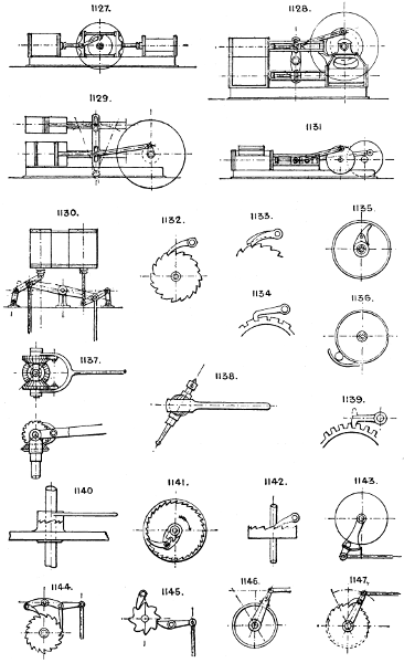
1127. Horizontal pumping engine, with yoked crossheads and crank in centre.
1128 & 1129. Horizontal compound lever engines.
1130. Davey’s patent vertical compound beam mining pump.
The Cornish beam pumping engine is too well known to need illustration.
In mining pumps the pump rod has occasionally been made of iron pipe and employed as the rising main.
1131. Geared pumping engine, with steam cylinder and pump side by side; the speed of the steam piston is reduced on the pump by spur gearing.
Section 62.—PAWL AND RATCHET MOTIONS.
INTERMITTENT MOTION.
1132. The common ratchet-wheel and pawl, or detent.
1133. Ditto, with compound pawls to check angular motion less than the pitch of the teeth.
1134. Locking pawl.
1135. Strut-action pawl.
1136. Indiarubber ball pawl; sometimes a solid roller is substituted for the indiarubber ball.
1137. Reverse ratchets, for continuous feed from an oscillating arm.
1138. Ball and socket ratchet, will work at an angle.
1139. Pawl, used with ordinary spur teeth, and sometimes made reversible (see dotted lines), to drive the opposite way.
1140. Ratchet bosses.
1141. Silent pawl; the pawl is lifted out of gear while reversing by the motion of the toggle joint and lever.
1142. Crown ratchet and pawl.
1143. Application of No. 1136 as a silent feed motion.
1144. Click and detent continuous feed motion.
1145. Hare’s foot ratchet motion with detent.
1146. Silent feed. The jaw grips the rim of wheel when moving in one direction and runs loose the other way.
1147. Reciprocating into intermittent rotary motion.
Larger plate.
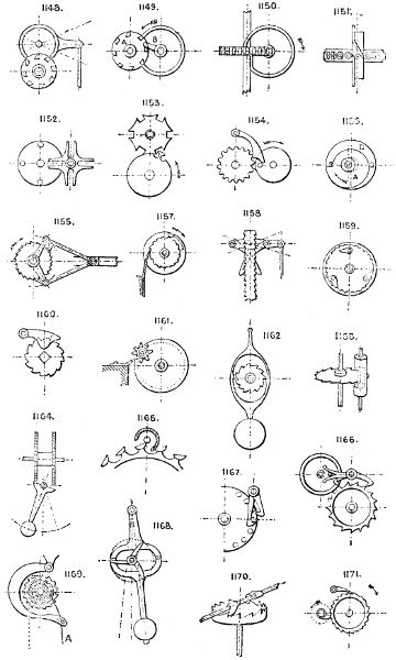
1148. Reciprocating circular motion into intermittent circular ditto, Kaiser’s patent.
1149. Continuous circular motion into intermittent ditto, Kaiser’s patent. The wheel A is locked by the ring C while the finger B is out of gear, the ring then passing between the teeth of A.
1150. Cam-ring intermittent feed motion.
1151. Modification of the last named; in both the wheel is locked during the dead movement of the cam by the flange passing between the teeth.
1152. Slot wheel and pin gear.
1153. Segment-wheel intermittent feed motion; locked during the dead movement of driving wheel.
1154. The pawl is lifted out of gear at each revolution of the pin wheel A and the ratchet moved one or more teeth.
1155. Double pawls and links for continuous feed motion.
1156. The cam A is eccentric to the wheel B, and slips out of gear at any required point while the driving wheel makes a partial revolution.
1157. Spring-pawl feed motion; the large wheel with pawl attached drives the ratchet wheel.
1158. Rocking lever and double pawls for raising a rack.
1159. Internal pawls, dropping into gear by gravitation.
1160. The pawl is lifted out of gear by the act of putting the handle on the square end of shaft, the handle having a boss shaped so as to lift the pawl.
1161. Star wheel and fixed pawl for conveying intermittent motion to screw on revolving disc; used for boring-bars, slide rests, &c.
1162. Pendulum and ratchet escapement.
1163. Cylinder escapement.
1164. Pendulum and double ratchet wheel escapement.
1165. Enlarged plan of cylinder escapement.
1166. Lever escapement.
1167. Double pawl and pin wheel escapement.
1168. Three-leg pendulum escapement.
1169. Self-sustaining ratchet motion. Pulling the cord A throws the pawl out of gear by the straightening of the cord forcing back the bent pawl lever.
1170. Verge escapement.
1171. Intermittent circular motion by revolving pawl and detent.
Larger plate.
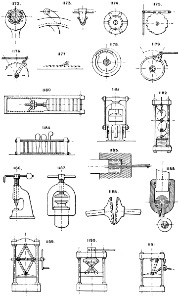
1172. Spanner ratchet; a simple spanner having a pin near one end of one of the jaws which slips into the teeth of the ratchet wheel.
1173. V pawl; operates by wedging itself between the V flanges.
1174. Gravity pawls and ratchet wheel.
1175. Ratchet wheel, used to govern the striking gear of a clock.
1176. The pawl is hinged to the jointed end of the lever, and is pulled out of gear by the return movement of the rod—silent feed.
1177. Pawl and rack.
1178. Roller and inclined segmental recess for silent feed motion.
1179. Gripping pawls and ring for silent feed motion.
Snail ratchet, No. 725.
Section 63.—PRESSING.
The ordinary Screw press and Hydraulic press are well-known machines.
1180. Rack and screw press.
1181. Power press or stamp, with double crank movement worked from below.
1182. Dick’s anti-friction press, with rolling contacts throughout.
1183. Hydraulic press, with dies for lead pipe making; a similar press is used for making earthenware drain and flue pipes, the material being forced out of an annular orifice.
1184. Wedge press.
1185. Ster-hydraulic press; a strand or rope is wound upon a barrel inside the cylinder, thus displacing the water and raising the ram.
1186. Screw fly press.
1187. Combined screw and hydraulic press. The screw is worked down by hand until the pressure becomes too great for hand power, when the pressing is finished by the hydraulic ram.
1188. Revolving dies.
1189. The “Boomer” double-screw toggle press, with increasing pressure as the press follower descends.
1190. Revolving toggle press, with similar capabilities but more restricted movement.
1191. Sector and link press for increasing pressure.
Larger plate.
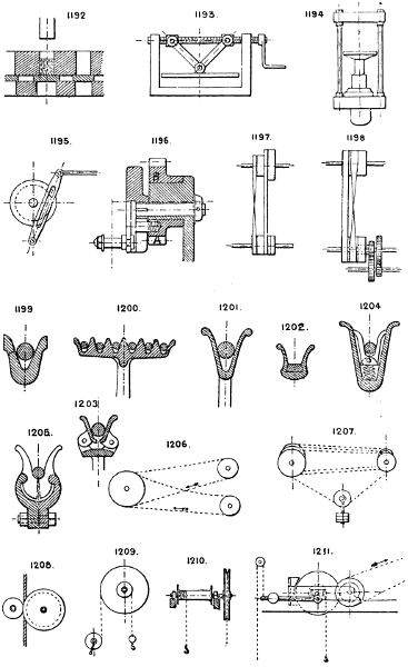
1192. Press dies, with sliding plate for discharging.
1193. Screw and toggle press; a modification of No. 1189.
1194. Double ram hydraulic press for two pressures; the small ram is employed to give the first pressure, the large ram then finishes the pressing.
See also Section 13.
Section 64.—POWER AND SPEED, CONTRIVANCES TO VARY.
(See Mechanical Powers, Section 53.)
Section 65.—QUICK RETURN MOTIONS.
Employed for machines having a slow movement one way, and a quicker return movement.
1195. Slot lever and crank motion; gives a varying speed, quickest when the crank pin is at the bottom centre, and slowest when at the top, with a slight pause at each end of stroke.
1196. Whitworth’s motion. The pin A in the wheel B travels eccentrically in the crank disc, which is eccentric to the fixed boss on which the driving wheel B runs, so that the radius of the driving motion of the pin varies as it revolves and it travels up and down the slot in the disc.
1197. By two belts, one open and one crossed, and driving drums of different diameters.
1198. By two belts, one open and one crossed, but driven by the same drum. The middle pulley is loose, the left hand pulley is fast to the spur wheel, and the right hand pulley to the spur pinion.
Segment gear, gearing alternately with the internal ring and the central pinion. See No. 724.
See Section 74.
Section 66.—ROPE GEARING.
1199. V-grooved pulley rim for round rope.
1200. Multiple pulley rim, used for rope driving in mills, &c.
1201. Single V-grooved pulley for hand ropes.
1202. Pulley for wire rope transmission, with wood bedding in the groove.
1203, 1204, & 1205. Clip pulleys, which grip the rope by its own tension.
Ordinary round grooved pulley. See Section 71, No. 1241.
Rope grip pulley, with snugs to wedge the rope and prevent slipping. See Section 71, No. 1242.
Pit head sheave. Used for quick running wire ropes. The boss is usually split to allow of expansion in cooling, and the arms are of wrought iron. See Section 71, No. 1243.
1206. Rope driving.
1207. Rope driving, with tightening pulley and weight.
1208. Rope grip pulleys, for driving a vertical rope, the large pulley has a V groove into which the rope is pressed by the small pulley.
1209. Jigger hoisting rope gear, used for whip cranes, &c., instead of spur gearing.
Wire rope transmission. Endless wire ropes of small diameter are used running over large pulleys and driven at a high speed (usually 3000 to 4000 feet per minute). This kind of power may be carried considerable distances and over uneven ground, but it is not desirable to have horizontal angles in the direction of the rope.
Section 67.—RESERVOIRS OF POWER. ACCUMULATORS.
a.
The fly-wheel or its equivalent.
b.
Springs. See Section 80.
c.
Weights.
d.
Air or gas compressed into a reservoir; air vessel, bellows. See Section 7.
e.
Water raised into an elevated reservoir or tank, or pumped into a loaded accumulator. Variable Pressure Accumulator, No. 1586.
f.
Electricity stored in accumulators.
g.
Explosives.
h.
Pendulum. Sometimes used to accumulate power to be given out suddenly, as in punching.
a. The fly-wheel or its equivalent.
b. Springs. See Section 80.
c. Weights.
d. Air or gas compressed into a reservoir; air vessel, bellows. See Section 7.
e. Water raised into an elevated reservoir or tank, or pumped into a loaded accumulator. Variable Pressure Accumulator, No. 1586.
f. Electricity stored in accumulators.
g. Explosives.
h. Pendulum. Sometimes used to accumulate power to be given out suddenly, as in punching.
Section 68.—RECIPROCATING AND CIRCULAR MOTION, CONVERTING ONE INTO THE OTHER.
(See Circular and Reciprocating Motion, Section 21).
(See Pawl and Ratchet Motions, Section 62).
Section 69.—RAISING AND LOWERING.
(1.) BY HAND POWER.
a.
The ordinary winch and crank handle.
b.
Winch, worked by an endless hand rope and wheel, similar to Nos. 1210, 1220.
a. The ordinary winch and crank handle.
b. Winch, worked by an endless hand rope and wheel, similar to Nos. 1210, 1220.
1210. Hand rope and barrel hoist. In this machine gearing may be interposed between the hand rope wheel and rope drum to increase the power and reduce speed.
c.
Differential blocks of various patterns (see Weston’s, Pickering’s, Moore’s, &c.). See Section 31.
d.
By screw gear, as in the ordinary screw jack. Sec. 78.
e.
Rack and pinion gear. See No. 754.
f.
Worm and wheel gear. See Section 84.
c. Differential blocks of various patterns (see Weston’s, Pickering’s, Moore’s, &c.). See Section 31.
d. By screw gear, as in the ordinary screw jack. Sec. 78.
e. Rack and pinion gear. See No. 754.
f. Worm and wheel gear. See Section 84.
Note as to brake wheels: these should always be upon the load shaft so that the braking is not transmitted to the load through toothed gearing. Worm gear usually will not sustain a load without a brake wheel, unless there is an excess of friction which should not exist.
g.
Friction gear. See Section 38.
g. Friction gear. See Section 38.
(2.) BY POWER.
This may be applied to any of the above as follows:—
a or b. To the ordinary winch by either gearing (see Section 84), belts (see Section 3), or friction gear (see Section 38).
b.
By gripping the endless rope between grip wheels (see 1208) the small wheel can be thrown into gear to grip the rope by a lever, cam or screw.
c.
Differential gear may be driven from a shaft by belts or gearing. See Sections 84 and 3.
d.
Screw gear. Ditto.
e.
Rack gear. Ditto.
f.
Worm and wheel gear. Ditto.
g.
Friction gear is usually driven as No. 1211.
b. By gripping the endless rope between grip wheels (see 1208) the small wheel can be thrown into gear to grip the rope by a lever, cam or screw.
c. Differential gear may be driven from a shaft by belts or gearing. See Sections 84 and 3.
d. Screw gear. Ditto.
e. Rack gear. Ditto.
f. Worm and wheel gear. Ditto.
g. Friction gear is usually driven as No. 1211.
1211. Where the barrel shaft has a slight horizontal movement, so that, by the lever, it can be forced into gear with the friction pinion to raise the load, or into the brake block to sustain the load or lower it.
Grooved friction V gearing is also sometimes used. See No. 667.
Larger plate.
(3.) HYDRAULIC GEAR. See Section 42.
The direct-acting plan is simply a ram and cylinder, as in the hydraulic press, the ram being as long as the height of travel of the cage. For multiplying cylinder hydraulic gear, see Section 42.
Balancing the dead load of cage, &c. This is usually done by weights attached to the end of ropes running over overhead pulleys and fastened to the cage, as in No. 370, or by an auxiliary cylinder and ram of short stroke loaded to the required weight, and communicating with the lift cylinder by a pipe. See Section 20.
(4.) FOR LOWERING WEIGHTS ONLY.
a.
An hydraulic cylinder and piston may be used, to which the cage is directly attached either above or below, the cage or platform being overbalanced by a counterbalance weight and rope (running over a pulley as No. 370), which is sufficient to raise it empty. The speed is controlled by a pass valve which allows the water to pass from one side of the piston to the other. See Section 5.
b.
An ordinary V wheel and brake wheel may be used, the cage being overbalanced as last described; the motion is controlled solely by the brake. Or, an hydraulic brake cylinder may be used in connection with a rope or chain attached to the cage. See note to Section 5.
a. An hydraulic cylinder and piston may be used, to which the cage is directly attached either above or below, the cage or platform being overbalanced by a counterbalance weight and rope (running over a pulley as No. 370), which is sufficient to raise it empty. The speed is controlled by a pass valve which allows the water to pass from one side of the piston to the other. See Section 5.
b. An ordinary V wheel and brake wheel may be used, the cage being overbalanced as last described; the motion is controlled solely by the brake. Or, an hydraulic brake cylinder may be used in connection with a rope or chain attached to the cage. See note to Section 5.
Other hoisting devices are:
Direct-acting steam or air cylinders, the piston rods being coupled direct to the cage.
Air vessels, on the principle of the gasometer, but of a height equal to the travel, and diameter proportional to the pressure of air employed.
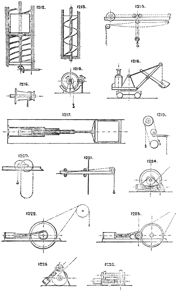
1212. Internal screw elevator. The vertical shaft has a feather groove, and carries a double crosshead with a wheel at each end, which run on the spiral guides and raise the cage.
1213. Screw elevator, for ice, &c. Vertical creeper.
1214. Travelling hoist, with in and out motion and rope.
1215. Steam digger and hoist.
1216. Hauling capstan. The rope, which is payed on and off the barrel, “fleets” itself as it travels along the barrel owing to its conical shaped flanges.
1217. Richmond’s patent differential telescopic hydraulic lift. The water under each piston is forced into the next cylinder above, so that the rams all travel upwards at proportional speeds, so as to reach the top of their stroke at the same time.
1218. Self-sustaining gear. The revolution of the pinion tends to lift the barrel and its brake wheel out of the brake; lowering is performed by relieving the brake wheel by a lever which raises it from the brake. Cherry’s patent.
1219. Belt hoist. Worked by a loose vertical belt, which is tightened by the lever and pulley when required to hoist, and in lowering a load the belt friction acts as a brake.
1220. Travelling hand hoist, with endless rope.
1221. Travelling cathead hoist. The cathead can be run back with its load; the winch is sometimes fixed to the travelling beam and moves in and out with it.
1222. Winding engine, usual type for direct acting.
1223. Geared winding engine.
1224. Steam winch, horizontal arrangement.
1225. Steam winch, diagonal arrangement.
1226. Steam winch, horizontal worm-gear plan.
Larger plate.
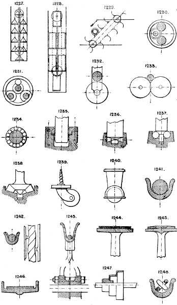
1227. Continuous lift, for parcels, &c. Has a number of small cages, boxes, or platforms suspended from horizontal pivots in two endless chains; the cages are guided so as always to hang vertical.
1228. Continuous lift, for passengers. Sometimes the cages are suspended from two endless chains at their tops, as last described; or sometimes from two endless chains, but with attachments to the cages at corners diagonally opposite each other; and sometimes from a single endless chain at the back, provided with guides, &c.
1229. Continuous barrel hoist.
See also Cranes, Section 18.
Section 70.—RELIEVING PRESSURE ON BEARINGS. ANTI-FRICTION BEARINGS.
1230. The pivots of two rollers or shafts bear against the inside of a stiff ring producing rolling contact, but the rollers or shafts must run in the same direction. Used for roller mills, &c.
1231. The same device, but for three rollers or shafts.
1232. The shaft is guided vertically and its weight is borne by a large roller with small pivots.
1233. The shaft runs in the V between two rollers as last described.
1234. Roller or ball bearing. The friction is least when the rollers have end pivots to run in loose rings so that the rollers are kept apart and do not rub each other in revolving.
1235. Hydraulic bearing, the shaft being sustained by water (or preferably oil) pressure.
1236. Vertical shaft, with cone rollers.
1237. Vertical shaft, with ball bearing.
1238. Vertical shaft, flanged and coned for cone rollers.
1239. Ordinary swivelling castor.
1240. Ball castor.
Section 71.—ROPE, BELT, AND CHAIN PULLEYS.
(See also Section 66.)
1241. Pulley for round rope without any grip.
1242. Round grooved pulley for round rope with gripping snugs.
1243. V pulley for round rope; pithead pulley.
Pulley for wire rope transmission, high speed with wood bedding. See Section 66, No. 1202.
Multiple rope gripping pulley for rope driving. See Section 66, No. 1200.
1244. Belt pulley, flat fare.
1245. Belt pulley, crown face. The rounding tends to keep the belt from running off.
1246. Flanged belt pulley.
1247. Speed cone for belt.
1248. Round grooved chain pulley.
Larger plate.
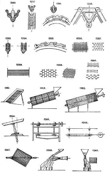
1249. Double grooved chain pulley; prevents the chain twisting.
1250. Pitched chain snug pulley or sprocket pulley. The pitch of snugs should be slightly longer than the chain, to allow for wear and stretching of the chain.
1251. Chain sprocket wheel, for long link chain at slow speeds.
1252. Sprocket wheel, for long flat link pitched chains.
1253 & 1254. Sections of rim showing single and double links.
1255. Sprocket wheel, for Ewart’s patent pitched chains. See Chains &c., Section 11.
Section 72.—RIDDLING AND SCREENING.
1256. Square mesh wire gauze.
1257. Perforated plate.
1258. Parallel bars or wires.
1259. Hexagon or triangular mesh wire work.
1260. Slit and square hole perforations, used for seeds, &c.
A form of variable mesh is manufactured by parallel series of diagonal bars jointed by pins to sliding cross-bars, so that the angle of the mesh bars can be altered and thus the spaces reduced or enlarged, on the same principle as No. 617.
1261. Sloping screen.
1262. Cylindrical or slope reel screen.
1263. Cylindrical graduated screen or sizer.
1264. Rotary screen, with rolling bevil gear motion. See No. 711.
1265. Rotary horizontal screen.
1266. Shaking or jigging screen. Sometimes supplied with a blast or aspirator to carry off the lighter particles.
1267. Eccentric or angular barrel screen or mixer.
1268. Air blast sizing or graduating apparatus.
1269. Edison’s magnetic sizing apparatus for iron or steel particles.
Larger plate.
1270. Graduating or sizing screens, either fixed as shown or kept in motion like No. 1266.
See also Concentrating and Separating, Section 26.
Section 73.—RAIL AND TRAM ROADS.
1271. Square bar rails.
1272. L-iron tram road; often made of cast-iron with the joints dove-tailed together.
1273. T-iron tram road.
1274. Tram road, with flanged plates for ordinary vehicles.
1275. Tram road, with one channel plate and one flat plate.
1276. Bridge rail.
1277. Bulb-head flanged rail.
1278. Double headed rail.
1279. “Barlow” rail.
1280. Bulb rail.
1281. Flush grooved tramway rail. See Nos. 1839-1841.
1282. Rolled joist rail.
1283. Bulb-iron rail.
1284. Edge’s patent perforated rail and toothed wheel.
Many forms of combined chair and sleeper are manufactured in wrought iron and steel.
1285. Left-hand switch.
1286. Shunting carriage, for transverse shunting; carries a short section of the main road and runs across it on independent rails laid on a lower level; often used instead of a turntable for shunting.
1287. Tramway switch.
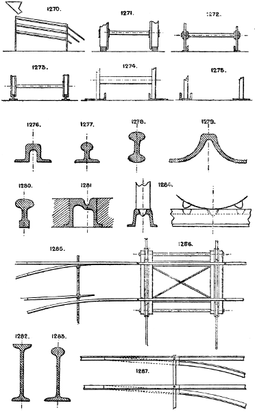
Larger plate.
1288. Right and left-hand switch and crossing, showing arrangement of guard-rails.
1289. Flat bar on edge rail.
See Section 99 for other sections of rails.
Section 74.—REVERSING GEAR.
For Reversing Gear of Steam Engines, see Section 79.
1290. Reversible driving motion by open and crossed belts, with two loose and one fast pulleys.
1291. Reversible driving motion by single belt, two fast pulleys and one loose ditto and bevil gear, one bevil pinion having a sleeve to which its fast pulley is keyed, the other bevil pinion being keyed to the shaft.
1292. Reversible driving motion by single belt, with quick and slow motions; a modification of the last.
1293. By double clutch and bevil gear.
1294. Reversing friction cones or bevils.
1295. Three-wheel gear. The driving wheel A can be put into gear either with the driven wheel C or idle wheel B.
1296. Double clutch and spur gear reversing motion, with idle wheel.
1297. Reversing pinions, as used on the ordinary screw-cutting lathe. There are many varieties of this gear in use.
1298. Application of single belt gear to No. 1296.
1299. Self-reversing gear, with one belt, two fast and one loose pulleys. The large spur wheel is driven from the bevil gear, and carries the weighted lever past the vertical position by a stop on the face-plate or disc, when it falls over and reverses the belt fork. See No. 1026.
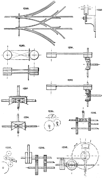
Larger plate.
1300. Self-reversing gear, as applied to planing machines. The stops can be set at any required distance apart, to alter the length of travel of the machine bed. This plan requires a heavy table to carry the belt across the loose pulley to the other fast pulley.
1301. Reversible belt-shifting hand gear.
1302. Right and left hand screw reversing traverse motion. Each lever has a half nut, which can be put in gear with the screw to drive either way. See also No. 163.
1303. Best form of fast and loose pulleys for open and crossed belt reversing gear, as used in No. 1290; the fast pulley is rather larger in diameter than the two loose ones.
1304. Single-belt reversing pulleys, the reverse motion on the shaft being obtained by intercepting an idle wheel A between the epicycloidal wheel B and the shaft pinion C, the middle pulley being the loose one; the idle wheel is carried by a fixed bracket and pin.
Note.—Reversible motion can be obtained direct from any steam engine fitted with reversing motion. See Valve Motions, No. 1436, &c.
Segment Reversing Gear, No. 724.
Section 75.—ROTARY ENGINES, PUMPS, &c.
Nearly all rotary engines can be used either as motors, pumps, blowers, or meters, and most of the following typical devices have been applied to all four purposes. Most of them are reversible by simply reversing the direction of the motor fluid.
1305. Disston’s; used as a pressure blower.
1306. Root’s, blower and pump.
1307. Root’s.
1308. Mackenzie’s; may have one, two, or three vanes.
1309. Gould’s.
1310. Bagley and Sewall’s.
1311. Greindl’s rotary pump.
1312, 1313, 1314, & 1315. Varieties of intergeared piston rotary engines.
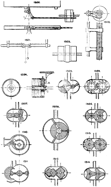
Larger plate.
1316. The small crescent-shaped piston revolves three times to one revolution of the three-armed piston.
1317. The hinged shutter is thrown out of the way each time the revolving arm passes it.
1318. Sliding shutter and cam piston device.
1319 & 1320. Varieties of the “Root” engine.
1321. The hinged vanes are closed upon the revolving piston as they pass the flat side of the casing.
1322. Has an eccentric piston and two hinged vanes.
1323. Eccentric piston and sliding diaphragm.
1324. Klein’s motion. The eccentric ring revolves in contact with the inner and outer casings, but is prevented from revolving on its axis by the fixed shutter and slot.
1325. Baker’s pressure blower.
1326. A modification of No. 1323.
1327. The eccentric ring revolves on its centre, allowing the vanes to alternately project into the steam space as the wheel revolves.
1328. Ivory’s. An eccentric cam and two sliding shutters, with a central steam inlet.
1329. Mellor’s has a rocking vane oscillated by an eccentric piston carried round by a crank.
1330. Eccentric piston and two sliding vanes or steam stops.
1331. Differential rotary engine, with elliptical gear (see Section 34), or Stewart’s differential gear (No. 554) may be employed.
The “Tower” spherical engine is a well-known form of rotary engine. See Engineer, August 10th, 1883.
1332. An eccentric four-armed piston, with four rolling stoppers or packings.
1333. Mellor’s patent pump has a rocking vane or partition, with packing device which accommodates itself to the revolving oval piston.
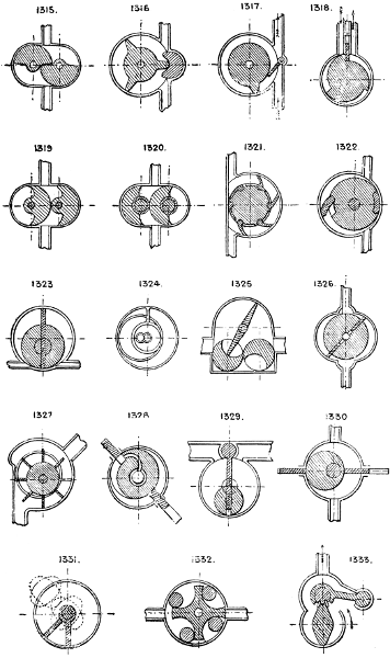
Larger plate.
1334. Bisschop’s disc engine, with three or four cylinders, single acting, whose rams press alternately on the edge of the disc.
1335. Another form of disc engine, in which partitions (rising and falling vertically) form the steam stops.
1336. A modification of 1316.
1337. Rotary or centrifugal pump or fan, numerous varieties of which are in use. Many of the later forms, as Blackman’s and others, have the vanes fixed diagonally so as to propel the air at right angles to the plane of motion.
Section 76.—SHAFTING.
Employed to convey motion from a motor to various forms of driven machinery by gearing of various kinds. See Sections 3, 11, 38, 40, and 84.
Materials employed are:—Round, square, or polygonal wrought iron or steel bars, cast iron, wood, iron or steel tubes, planished round iron and steel bars, &c.
Stow’s flexible shafting. See No. 442.
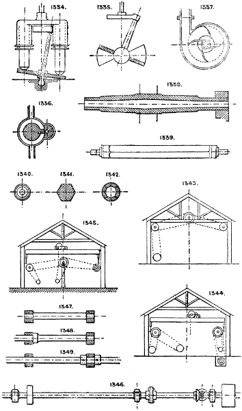
1338. Longitudinal section of a cast-iron shaft. These are sometimes made of a X section.
1339. Wooden shaft with end ferrules and iron end centres.
1340, 1341, & 1342. End view and sections of ditto, solid hexagonal and hollow circular.
1343, 1344, & 1345. Arrangements of line shafting in a machine-shop or factory, with or without overhead travelling crane.
1346. Example of a line shaft, showing bearings (see Section 46), couplings (see Section 16), pulleys (see Section 3), and gearing (see Sections 3, 84).
Shafts to be used as rollers are usually made hollow of wrought iron or other metal tube, tin plate, zinc plate, or sheet iron riveted; or sometimes, as No. 1342, of wood laggings fixed to solid polygonal blocks or centres, either continuous or in short pieces fixed at intervals.
See also next Section (77).
Section 77.—SPINDLES AND CENTRES.
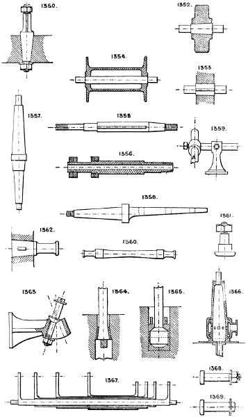
1347. Spindle with sunk end bearings.
1348. Spindle with one sunk bearing and one collar.
1349. Plain spindle with two loose collars. Where pedestals with loose caps are used (see Section 46) the collars may be solid with the spindle, but with a long shaft the collars should be at one end only as shown, to allow of expansion. A wheel frequently occupies the place of one or both collars, and serves the same purpose.
Larger plate.
1350. Coned centre, fixed.
1351. Collar centre pin or stud bolt, fixed.
1352. Coned centre for roller or similar detail, driven in place.
1353. Parallel centre for roller or similar detail, keyed in place.
1354. Square centre for crane barrel, &c. See Nos. 634 and 635.
1355 & 1356. Lathe headstock spindles, solid or hollow; sometimes made with conical and sometimes with parallel necks.
1357. Conical crane post.
1358. Conical cart axle.
1359. Universal centres, employed to allow of a machine (or part of ditto), such as a drill, to be adjusted at any possible angle, the machine being fixed to one end of bar A.
1360. Railway carriage axle. For cranked axles, see Section 10.
1361. Square neck centre bolt. The square neck prevents the bolt turning and loosening the nut.
1362. Coned and cottered crank pin or centre, sometimes secured by a nut, as No. 1350.
1363. Centre pin and bracket, adjustable to various angles.
1364 & 1365. Two methods of securing end of rod to any solid part of machine; used for steam hammer heads.
1366. Hollow post centre, with water or steam channel to allow for swivelling.
1367. Group of sleeve centres, employed to allow of several pairs of lever or wheel motions being taken independently on a single shaft.
1368. Ordinary centre pin, with nut, washer, and split pin.
1369. Ordinary centre pin, with split pin and washer.
Larger plate.
Section 78.—SCREW GEAR, BOLTS, &c.
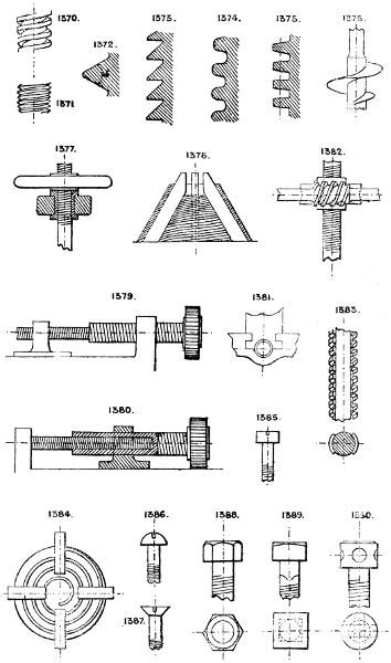
1370. Square thread screw. Single, double, or multiple thread.
1371. V thread screw.
1372. Enlarged section of V thread.
1373. Strongest thread when the strain is always in one direction.
1374. Round thread screw.
1375. Geared thread, to be used with ordinary wheel teeth, the section of thread being that of a rack of the same pitch as wheel.
1376. Earth screw, screw pile, screw mooring, earth borer. See No. 530.
1377. Fixed screw, with hand wheel to revolve the nut, the screw having no rotation.
1378. Conical screw; used for chucks, &c. With two, three, or more sliding jaws chased to fit the conical thread.
1379 & 1380. Differential screws. One fixed, the other revolving, impart a motion equal to the difference of pitch of the two screws (see Section 31). See No. 1430.
1381. Screw, with half nut; the bearings of the screw being fixed act as a fulcrum for the motion of the half nut, which may be attached to any sliding device; employed for jaw chucks.
1382. Screw and worm gear, used for screw jacks, &c. The worm gears with a worm wheel having a central nut running on the main screw.
1383. Mutilated screw and nut. In one position the nut can slide on the screw, and a partial turn locks it. Used for instantaneous grip vices, &c.
1384. Spiral worm for three or four jaw chucks, expanding devices, &c.
See Sections 28 and 36.
1385, 1386, & 1387. Screw driver heads for screws.
1388 & 1389. Hexagon and square heads for ordinary spanners.
1390. Form of head requiring special spanner or pointed bar.
Larger plate.
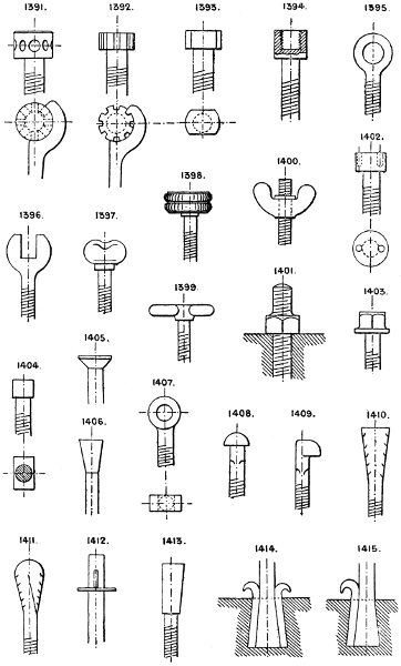
1391. Cylinder head bolt, with drilled holes and special spanner.
1392. Cylinder head, but with flutes instead of holes for spanner.
1393. Cylinder head, but with two flats cut on the head to suit an ordinary spanner.
1394. Socket head, to receive a second screw.
1395. Eye bolt.
1396. Thumb screw.
1397. Thumb or shutter screw.
1398. Milled head screw.
1399. T head screw.
1400. Thumb or fly nut and screw.
1401. Hexagon collar stud to receive a nut or other female screwed fixing.
1402. Bolt head for forked spanner, used for sunk or countersunk heads.
1403. Hexagon head, with solid washer or collar.
1404. T head bolt for T grooves in castings.
1405 & 1406. Countersunk heads.
1407. Eye bolt, with flat sides and straight eye for a pin or bolt.
1408. Snap head.
1409. Hook bolt.
1410 & 1411. Lewis bolts, rag bolts.
1412. Cottered bolt.
1413, 1414, & 1415. Lewis bolts and key pieces.
Larger plate.
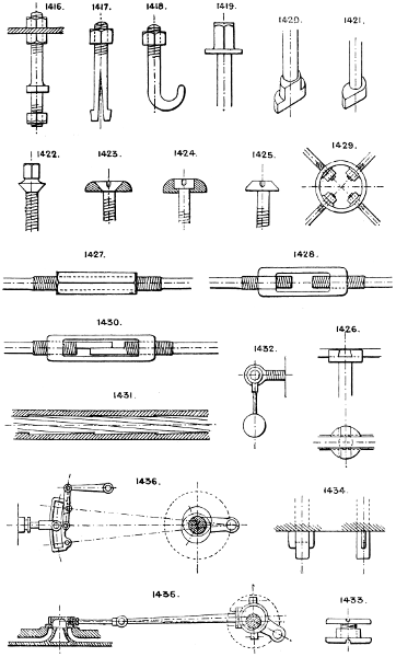
1416. Collar stud.
1417. Split spring head bolt.
1418. Hook bolt.
1419. Solid head and collar bolt, bed bolt.
1420 & 1421. Heads for bolts to slide and turn in T grooves of planing machines, &c.
1422. Countersunk bed bolt. Boiler stay.
1423, 1424, & 1425. Methods of finishing screw heads to prevent catching passing articles.
1426. Screw head, with cross dovetails to carry a key or screwing lever.
1427 & 1428. Right and left-hand screw couplings for tie rods, &c.
1429. Ring coupling for 2, 3, 4 or more rod ends for tie bracing.
1430. Right and left-hand screw couplings with halved ends to prevent the rods turning; may be made with one fine and one coarse thread for differential motion, or with right and left-hand threads.
1431. Rifling, as used in ordnance, &c., i.e. an internal multiple screw thread of very long pitch.
1432. Screw spanner; the weight prevents it working loose.
1433. Belt screw.
1434. Gib cotter bolts.
See also pipe couplings, Nos. 1071, 1072, 1073, 1074, 1075, and 1062, 1068, 1070.
For spiral worms and creepers, see Section 57.
Spiral pump, No. 1022.
Note that it is possible to construct a screw with an increasing or decreasing pitch, as is done with the screw propeller. See also No. 1378.
Double screw gear, No. 727.
Snail worm gear, No. 730.
Worm and crown gear, No. 733.
Worm and spiral gear, see Section 84.
Section 79.—SLIDE AND OTHER VALVE GEAR.
It would be neither easy nor useful, besides being beyond the scope of this work, to attempt to illustrate all the varieties of gear employed to work the valves of steam and other motor engines. I shall therefore only illustrate the more important types in general use, the details of which may be varied to suit individual cases.
1435. Is the ordinary slide valve gear with single eccentric for engines running always in one direction.
1436. Ordinary link motion reversing gear with two eccentrics; the link, having a shifting motion, is so arranged that either eccentric can be put into gear with the slide valve, the other eccentric running idle; or when in the mid position, as in sketch, both eccentrics run idle and the slide valve has no motion. By setting the link at intermediate positions the travel of the valve can be varied, and consequently the cut off also within certain limits.
Larger plate.
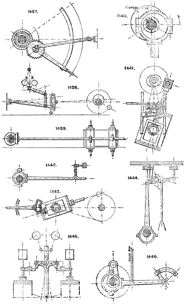
1437. Nicholson’s patent reversing gear, without eccentrics. The drawing explains itself. This gear cannot be run in the intermediate positions, as a link motion to vary the cut off. This limits its usefulness to simple reversing only.
1438. Automatic governor expansion for single eccentric engine; the position of the connecting rod end in the swinging link is dependent on the governor, and thus also the travel of the slide valve.
1439. Side shaft motion for operating Cornish, Corliss, and spindle valves. The valves can be driven from this shaft by cams, eccentrics, or gearing.
1440. Gab lever for throwing the eccentric out of gear and thus stopping the engine.
1441. Sector and link reversing motion for oscillating engine; sometimes a shifting eccentric is used instead of link motion, as No. 1443.
1442. Reversing sector link motion for an oscillating engine; the valve is operated from the link, the angle of which is altered by the hand lever, there is therefore no lead to the valve.
1443. Shifting eccentric and balance sometimes used for reversing instead of double eccentrics and link; the loose eccentric is carried round in either direction by a stop piece on the shaft, fixed so as to give the correct lead both ways.
1444. Murdoch’s variable expansion gear (see Mechanical World, September 29th, 1888) has one eccentric which operates a double arm lever, the outer end of which moves a sliding fulcrum along the valve rod lever, so that the leverage of the valve rod lever varies at different parts of the stroke. The sliding fulcrum is attached to a radius rod.
1445. Proell’s automatic expansion gear. Shown applied to special double beat valves, but is sometimes applied to a special throttle valve, and is then applicable to any ordinary engine. The action of the governor alters the lap of the catches upon the ends of the valve levers, thus varying the time that the valves are kept open; the catches are centered on an oscillating T lever, operated from an eccentric on the main shaft.
1446. Marshall’s valve gear, driven by one eccentric on crank shaft. The sector rocking centre is moved along the curved slot to reverse the engine, giving similar motion to the valve rod as in the case of the ordinary link reversing gear No. 1436.
Larger plate.
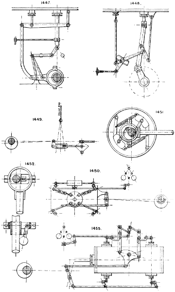
1447. The Bremmé valve gear with single eccentric; the valve rod is operated by a lever and bent connecting rod from the end of the eccentric rod; the latter is constrained to move in an arc by a three-link attachment to a fixed bearing behind the eccentric rod and a movable one at the right-hand end of the horizontal link. To reverse, the arm and sector are turned to the dotted position by the worm and hand wheel shaft.
1448. Joy’s valve gear, operated by a pin on the connecting rod. The slotted T lever is connected to the hand lever for reversing, and when reversed stands at the same angle from a vertical line but on the opposite side. The fulcrum of the valve rod lever has a sliding motion in the slot of the T lever.
1449. Variable expansion gear by hand power. There are many applications of this type used to vary the travel of a cut-off valve.
1450. Corliss valve gear, operated by a single eccentric, has two steam and two exhaust valves similar to No. 1642, worked from pins on a rocking wrist plate. The steam valves have trips, regulated by the governor, on a similar principle to No. 1445.
1451. Crank shaft governor with shifting eccentric: the centrifugal action of the weights, acting against springs, is used to revolve the inner eccentric so as to vary the throw of the main eccentric from which the slide valve is driven.
1452. Another form: in this also the throw of the eccentric is varied by the action of the governor ball.
1453. Another form of automatic governor expansion trip gear in connection with Cornish valves; a single eccentric operates the four valves, and the contacts of the catches and steam valve levers are regulated by the governor, the lower or exhaust valves having a constant motion.
Larger plate.
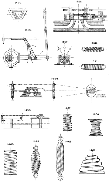
1454. Double angular slide valve for varying the cut off by a transverse motion given to the valve from outside, either by hand gear or by the governor, the valve being made wider than the valve face, as dotted lines.
1455. H. Jack’s variable expansion gear, with one eccentric. Patent No. 4167/85.
1456. Variable cut-off valve on the back of the main slide, the rod of which can be revolved by hand or from the governor to vary the opening of the cut off valves.
1457. A plan to effect the same object but by a cylindrical cut off valve.
1458. English’s expansion gear. Two eccentrics. The expansion valve has no lap, and the gear gives a constant relative motion to both valves.
1459. Tappet gear, sometimes used for water-pressure engines, &c.
Section 80.—SPRINGS.
1460. Open spiral spring for tension.
1461. Close spiral spring.
1462. Open spiral spring for compression.
1463. Open spiral spring (square thread) for compression.
1464. Double volute chair spring.
1465. Spindle-shaped open or close spiral spring for tension.
1466. Parallel open or close spiral spring with coned ends.
1467 & 1468. Volute springs.
Larger plate.
1469. Torsional spiral spring.
1470. Wire staple torsional spiral spring, used for hinging; the ends of the wire are bent at a right angle and driven into the wood.
1471. Fixed spring.
1472 & 1473. Sear springs.
1474. Flat spiral spring.
1475. Plate spring.
1476. Indiarubber spring for tension.
1477. Wire spring.
1478. Ribbon spring for torsion.
1479. Compound rubber disc spring.
1480. Air cushion or spring piston.
1481. Laminated plate wagon spring.
1482. Compound dished disc or bent plate spring.
1483. Loop spring.
1484. Flat spiral spring, clock spring or coil spring.
1485. Split ring spring.
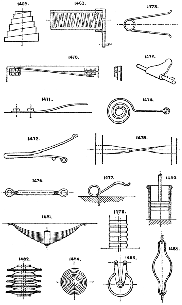
Larger plate.
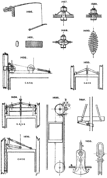
1486. Spring pole for foot hammer motion, &c.
1487 to 1489. Spring washers.
1490. Spindle-shaped compression spring.
1491. Flat spiral spring for piston rings.
See also Nos. 1729, 630, 1501, 1503, 11, 767, 768; and Section 35 (Elastic Wheels) for other forms of springs and applications of them.
For equalising the tension of a spring, see No. 1592 and 1602.
Section 81.—SAFETY APPLIANCES FOR VARIOUS USES.
FOR HOIST CAGES, &c.
1492. Cam gear; operates by gripping the wood guides by a serrated eccentric cam surface on the breakage of the rope, the cam being pulled round by a spring which is kept out of action by the tension of the rope until it breaks.
1493. Strut or pawl gear; explains itself.
1494. Double wedge gear.
1495. Governor gear. The rope attached to the cage drives a governor acting on a brake or catch which is thrown into action if the cage gains excessive speed, used in Attwood Beaver’s Patent; American Elevator Co., &c.
1496. Rack and pawl gear.
1497. Cross grip lever gear.
1498. Safety hook to prevent accident from overwinding; the projecting horns A A strike the edges of the plate B, and throw the shackle C at top out of gear.
For hoist doors the best appliance is an ordinary spring lock opened only by a key, the doors being provided with springs to close them. Various automatic doors, revolving shutters, and other devices have also been tried. A simple and effectual protection is a continuous open-work screen wound upon a roller at top and bottom of lift, and attached to the top and bottom of cage and rising and falling with it, so that the doors into lift are all covered at all times except the one at which the cage happens to stand.
Safety valves (see Section 89). Various automatic alarm signals are applied to boilers to warn against low water or excessive pressure.
Automatic valves and other devices are applied to pumping and steam engines to prevent running away. See note to Section 41.
Larger plate.
Section 82.—STEAM TRAPS.
To collect and discharge condensed steam from pipes, &c.
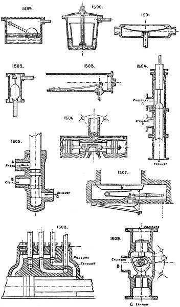
1499. Trap operated by a modified form of ball cock, which rises as the box fills with condensed water and opens the discharge valve.
1500. Effects the same object by a floating basin. The condensed water enters the box outside the basin, fills it, and lifts the basin which closes the discharge outlet; when the box is full the water overflows into the basin and sinks it, thus opening the outlet valve.
1501. Trap operated by expansion of a bent spring which closes the valve, on the principle that live steam is hotter than the water condensed from it.
1502. Tredgold’s trap. The valve is opened by a simple float.
1503. Wilson’s trap, like 1501, is dependent on the different expansion of a spring under the difference of temperature of the steam and condensed water. In this case the spring is formed of a steel and brass plate riveted together.
There are many other forms upon similar principles to the foregoing.
Section 83.—STARTING VALVES.
The valves used for starting steam and other engines are usually merely of the ordinary screw down or sliding types. See Section 89.
For starting and controlling all other forms of reciprocating cylinder motors, such as hydraulic lifting cylinders and presses for all purposes, the ordinary slide valve with either two or three ports is the common device; also the ordinary three or four way cock. See Section 89.
1504. Locke’s 3-way balanced valve, which is balanced in all positions. A is the supply, B the cylinder branch, and C exhaust.
1505. Fenby’s 3-way equilibrium starting valve. A supply, B cylinder branch, C exhaust.
1506. Auxiliary valve and pistons to start large slide valves too heavy for direct hand power. A 3-way cock is shown as the auxiliary valve, but a small slide valve or piston valve may be substituted. See note at foot of Section 93, also Nos. 1740 and 1741.
1507. Auxiliary valve and bellows for air, as sometimes used in large organs to open heavy “pallets.” The small valve A is opened by the pressure of the finger on the corresponding key of keyboard, and allows the pressure of air to enter the small bellows which operates the large valve B.
1508. Four plunger valve, used for double power hydraulic lift cylinders employing a trunk piston. For the low power the pressure water acts on both sides of the piston; for the double power it acts only on the back of piston, the front side being then open to the exhaust.
1509. A starting valve, having two ordinary wing or spindle valves, either of which is lifted by a double cam or wiper on a spindle passing through a stuffing box on side of valve case. A supply, B cylinder port, C exhaust.
Larger plate.
1510 & 1511. Two methods of operating starting valves for hydraulic lifting machines. 1510 acts by counter balance weights and a single rope, each of the weights being heavy enough to move the valve, and 1511 by an endless rope.
1512. Low pressure starting valve, used for piston hydraulic cylinders in which the lifting is performed by the down stroke of the piston rod, and in lowering, the valve allows the water to pass from above to below the piston, the water being exhausted from below the piston on its down stroke when the valve is in the position shown.
1513. Oscillating valve, with plunger face kept up by a spring. The oscillating valve has two ports passing out at opposite ends, through stuffing boxes, to either end of the cylinder; the inlet is at top and discharge at bottom.
1514. Balanced self-acting starting valve, suitable for large machines and low pressure. The upper piston is larger than the lower or main piston, and the space above the upper piston can be put in communication with the pressure water below it, or the exhaust port by the small piston valve at top operated by the hand gear; so that the main piston is operated by the pressure water acting on it.
Section 84.—TOOTHED GEARING.
1515. Spur gearing. For construction of teeth see text books.
1516. Strongest form of spur teeth for motion in one direction only.
1517. Half shrouded spur teeth.
1518. Whole shrouded spur teeth.
1519. Double helical spur teeth, stronger by 15 per cent. than straight teeth; work without backlash or noise, and may be half or whole shrouded; section of tooth on plane of motion is the same as the ordinary spur teeth (No. 1515).
1520. Crown wheel and pinion.
1521. Long teeth spur wheels or “star” wheels. Used on roller mangles, &c., where the centres rise and fall.
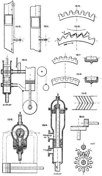
Larger plate.
1522. Plain bevil gear; shafts at right angles.
1523. Plain bevil gear; shafts at acute angles.
1524. Plain bevil gear; shafts at obtuse angle.
1525. Plain bevil gear; four shafts at right angles.
1526. Skew bevils; shafts not in line with one another.
Note.—Where the pair are both of same diameter they are called “mitre wheels.”
1527. Spur wheel and pinion; to increase or decrease power and speed the diameters can be varied to almost any proportion.
1528. “Screw gear”; single helical gear.
1529. Skew spur wheels; shafts not parallel.
1530. Dr. Hooke’s gear. Three or more separate wheels of similar or dissimilar pitch fixed together so as to divide the pitch and reduce backlash.
1531. The same result obtained by two wheels, one fixed to shaft, the other loose and forced round by a spring so as to follow the pitch of the pinion and destroy all backlash.
1532. Mortise wheel teeth.
1533. Mortise wheel teeth; another method.
Note.—Wood teeth are usually one-third thicker than the iron teeth they gear into.
1534. Pin wheel and pinion gear.
1535. Lantern wheel.
1536. Screw gear, used in place of bevil gear. Shafts at right angles; teeth at an angle of 45°.
1537. Variable speed cone gear.
1538. Variable speed square gear.
1539. Variable speed oval or elliptical gear.
1540. Irregular gear.
1541. Internal or epicycloidal gear. See Nos. 550 and 1545.
Used for differential blocks, &c. Note that both wheel and pinion run in the same direction, and that more teeth are in gear at one time than with external gear as No. 1527.
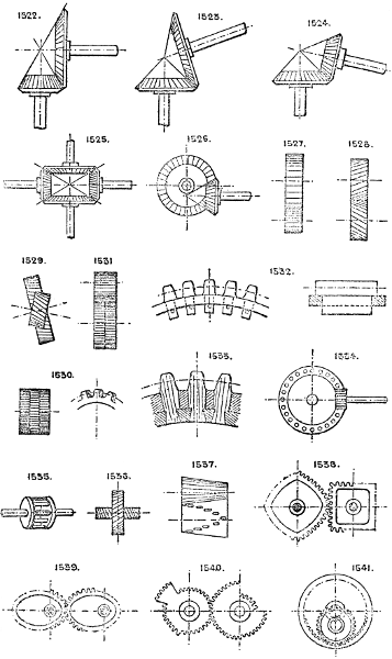
Larger plate.
1542 & 1543. Varieties of “mangle” gear. The pinion being revolved continuously in one direction produces a reciprocating motion of the wheel; the pinion shaft travels from inside the wheel to outside, and vice versâ, by rising and falling in the slot in the frame. See also No. 423.
1544. Differential gear. See Section 31. One wheel has one or more teeth more than the other; used for counters, &c.
1545. Moore’s patent differential epicycloidal gear. The pinion and wheel are loose on the shaft and eccentric. One wheel has one tooth more than the other.
1546. Multiplying bevil gear. A is a fixed wheel, the cross C is keyed to shaft, B loose on ditto, D and E loose on C; then B is driven at a speed greater than the shaft in proportion to the diameters of the gear. See Patent No. 12,696, 1884.
1547. Double worm gear, right and left hand threads. Neutralises the end thrust on shaft. A and B may be geared together.
1548. Pointed gear; used for light work and for minimum of friction.
1549. Curved worm gear, for heavy strains. Several teeth are in gear at once, but the thread, having a varying section and pitch, is difficult to cut.
1550. Antifriction worm gear (Hawkins’). The wheel has four rollers; when one pair is nearly out of gear with the worm, the next pair is coming into gear. This worm is also difficult to cut.
1551. Crown worm gear.
1552. Ball joint mitre gear.
1553. Multiplying rack gear. The upper moving rack is driven at twice the speed of the spur wheel rod. The lower rack is fixed; used on planing and printing machines.
1554 to 1557. Varieties of worm gear, with straight, hollowed, and curved teeth; the latter are strongest.
1558. Worm and rack gear.
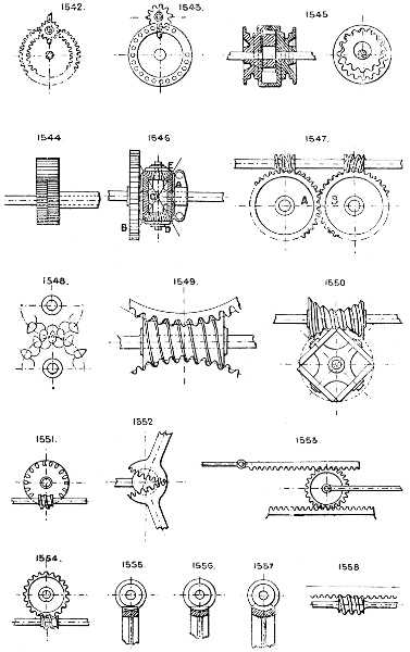
Larger plate.
1559. Differential worm gear. The worm gears into two wheels, one having one tooth more than the other.
See also Sections 40 and 31.
Section 85.—TRANSMISSION OF POWER.
a.
By belt, chain, or rope. See Sections 3, 66.
b.
By shafting. See Section 76.
c.
By gearing. See Sections 84 and 40.
d.
By steam or air conveyed in pipes (elastic fluids).
e.
By water, glycerine, or oil conveyed in pipes (non-elastic fluids).
f.
By stiff rods running over guides.
g.
By wires or ropes running over guide pulleys—wire rope transmission. See Section 66.
h.
By electricity conveyed along wire conductors.
a. By belt, chain, or rope. See Sections 3, 66.
b. By shafting. See Section 76.
c. By gearing. See Sections 84 and 40.
d. By steam or air conveyed in pipes (elastic fluids).
e. By water, glycerine, or oil conveyed in pipes (non-elastic fluids).
f. By stiff rods running over guides.
g. By wires or ropes running over guide pulleys—wire rope transmission. See Section 66.
h. By electricity conveyed along wire conductors.
Section 86.—TANKS AND CISTERNS.
1560. Plan of square tank of ordinary form; formed of cast iron flanged plates and wrought iron tie rods, the joints are either made with rust cement or planed and jointed with tape and red lead.
1561. Plan of square tank with rounded angles.
1562. Circular tank. No tie rods required.
1563. Elliptical tank. Requires tie rods across the flat sides.
1564. Polygonal tank. No tie rods required.
1565. Elevation of square or polygonal tank.
1566. Elevation of cylindrical or circular tank.
1567 & 1568. Condensing or cooling tanks. Surface condensers with sloping trays or tubes.
1569. Wrought iron tank, usual section, formed of sheets and L irons riveted together.
1570 & 1571. Circulating or depositing tanks.
1572. Boiler saddle tank.
1573. Circulating tank for hot water.
The level of water may be maintained in tanks by either an overflow pipe or notch, or by a ball cock on the supply pipe. Glass water gauges can be fixed outside to show the level of the water inside; and floats are used, attached to a cord and pulleys, for the same purpose. See also No. 1730.
Section 87.—THROWING IN AND OUT OF GEAR.
1574. The driving wheel is loose on shaft, and is locked to its shaft by the hand wheel nut (see No. 945), or by a ratchet wheel and locking pawl.
1575. Two half-nuts are lifted in or out of gear with the screw by cam or lever motion. See No. 942.
1576. One shaft runs in eccentric bearings, which can be revolved so as to throw it out of gear with the other shaft.
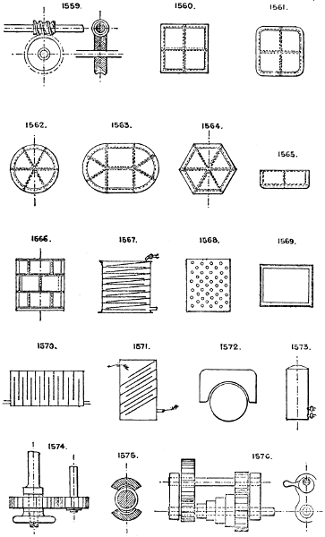
Larger plate.
1577. Radius bar and slot. The stud wheel can be shifted in or out of gear along the slot.
1578. Sliding back shaft, slides out of gear. See dotted lines.
1579. Method of throwing a pulley out of gear by slacking the belt. This is done either by a cam bearing or sliding motion to the driver shaft. Works best vertically. See also No. 1219.
1580. Cam slot motion for back shaft. To throw it in or out of gear.
1581. Motion employed for punching machines, &c. To set the punch in or out of action by a cam and hand lever.
Section 88.—VARIABLE MOTION AND VARIABLE POWER.
For variable speed and power by spur gear, see Sections 84 and 40.
For variable speed and power by bevil gear, see Section 84.
For variable speed and power by cam gear, see Section 9.
For variable speed and power by belt gear, see Section 3.
1582. Variable speed belt cones, for crossed belts. Angle of cones should not exceed 15°.
1583. Stepped cone gear.
1584. Variable throw crank pin. (See Hastie’s Patent, 3561, 1878; Knowelden and Edwards’, 2996, 1858.)
1585. Beam motion, with variable fulcrum to alter the proportionate lengths of stroke of driving and driven cylinders. See also No. 1606.
1586. Variable pressure accumulator. Both cylinders are in communication by a pipe, and the pressure varies with the angle between the rams.
1587. Wright’s variable gear. The radius of frictional contact of the wheels varies as they are moved closer together or separated.
1588. Olmsted’s variable cone friction gear, with intermediate double cone idle wheel instead of belt.
1589. Convex and concave cones for open belts.
1590. Three speed gear, each separate pair of spur gear being driven by its own belt pulley on separate sleeve pieces.
1591. Irregular or elliptical gear.
1592. Lever combination to obtain an even tension from a spring throughout its motion.
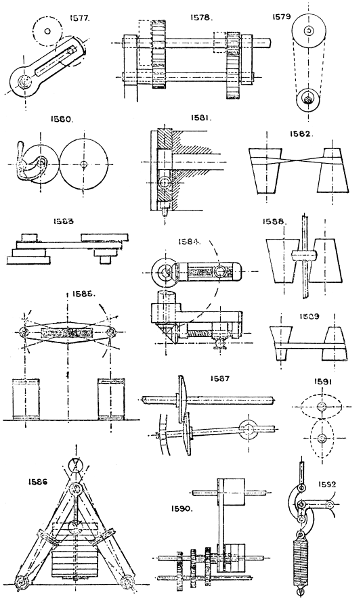
Larger plate.
1593. Scroll spur gear.
1594. Scroll gear for obtaining a variable pull from a weight.
1595. Variable friction gear. The pinion can be moved up or down from the centre to the outside of disc to vary the speed.
1596. Owen’s compound lever variable pressure air pumps. The pressure increasing and speed decreasing as the pistons rise to the top of their stroke.
1597. 2-speed gear by one belt. One loose pulley B carries a transverse mitre wheel, which, gearing into the fixed mitre wheel A, drives the mitre wheel pulley C keyed to shaft at twice the speed of pulley B when the belt is on B; by shifting the belt to pulley C, the speed is 1 to 1. The third pulley is loose for running idle.
1598. 2-speed bevel gear with three wheels and sliding shaft, by which either pair can be put into gear.
1599. 2-speed bevel gear with four wheels and sliding shaft.
1600. Increasing speed cone and screw, friction gear. The cone is driven by frictional contact with the pinion.
1601. Variable fulcrum lever, with shifting pin and hole adjustment.
1602. Fusee barrel, as used in clocks and watches to equalise the tension of spring on the movement; may also be employed to give a variable speed. The spring is usually similar to No. 1484, and coiled in the upper barrel.
1603. Variable throw crank pin and slot, much used for variable feed motions in combination with some type of pawl and ratchet gear.
1604. Variable travel imparted to the piston rod from the crank by altering the point of attachment of the link A to the slot.
1605. Variable power pistons, single-acting.
1606. Effects the same ends as No. 1601 or 1585, by shifting the fulcrum point along the slot by means of a screw.
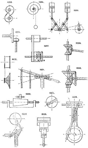
Larger plate.
1607. Variable throw crank pin by means of a jointed crank and radial adjusting screw.
1608. Variable throw crank pin by attaching the crank pin to an eccentric disc. See Section 10.
1609. Wind motor-fan or turbine, with variable-angle vanes actuated by a central sleeve and cam or lever gear.
1610. Variable friction cone gear; the small friction pinion can be moved radially to and fro to alter the leverage and consequently speed of driving radius from the cone.
In the steam engine, compressed air engine, and gas engine (these being all elastic fluids), the power given out is varied by altering the supply of steam, air, or gas. In the water wheel the power may be varied by altering the quantity of water (or head of water) supplied to the wheel. In the turbine the power can be varied by altering the head of supply water and the angle of vanes; altering the quantity reduces the speed and efficiency. The turbine will not work well under great variations of either head or quantity.
See also Nos. 736, 722, 723, 1190, 1191, 381, 382, 384, 385, 377, 372, 373; and Sections 20 and 40.
For variable pressure or tension by springs, see Section 80.
Variable balance weights, Section 20.
Section 89.—VALVES AND COCKS.
Of the almost innumerable varieties of valves and cocks in use the following are selected as types without reference to special uses, each type having its peculiar value, and the drawings are only intended to indicate the special features of each type without such details as may be varied to suit each particular requirement or application.
1611. The common plug cock.
1612. The same, but with screwed gland.
1613. 2-way or 3-way plug cock, with packed gland.
1614. Hollow plug blow-off cock, with packed gland.
1615. Back pressure or check valve, self closing.
1616. Ball valve and guard, self closing.
1617. Indiarubber disc and grating valve.
1618. Double flap indiarubber or leather and grating valve.
1619. Simple flap valve faced with rubber or leather.
1620. Rocking or rolling valve. For opening and closing gradually and easily against pressure.
1621. Roll-up valve. For same purposes as the last named.
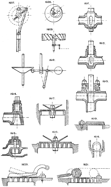
Larger plate.
1622. Sector full-way screw down valve, shown closed; when open the disc is up in the chamber out of the waterway.
1623. Double face valve; the spindle is screwed into the stuffing-box neck and the lower valve, the upper one being pinned to the spindle; the thread in the lower valve is twice the pitch of the upper thread.
1624 & 1625. Spring relief valves; the springs are adjusted to blow off at any stated pressure, which may be regulated by a screw or nut (not shown).
1626. Weighted lever relief valve or safety valve.
1627. Reducing valve, can be adjusted by the balance weight to pass fluids from a high pressure to any lower pressure.
1628. Another form, with spring balance adjustment and equilibrium valve.
1629. Equilibrium valve.
1630. Equilibrium valve, not steam tight, but serrated, to cut off gradually, employed for governors of steam engines.
1631. Equilibrium cylindrical grating valve, may be used to open and close either by vertical or revolving motion.
1632. Common throttle or butterfly valve.
1633. Duplex throttle or damper for a three-way pipe or flue.
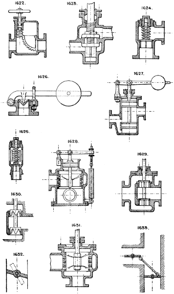
Larger plate.
1634. Hydraulic high-pressure check valve, with long guide wings.
1635. Hydraulic plug or spindle valve and seating; all seatings for high pressure should be narrow and hard.
1636. Duplex or Ramsbottom safety valve; each valve serves as a fulcrum by which to lift the other. One fulcrum point should be jointed to the lever and the latter move in a vertical guide, or else the point of attachment of the spring to the lever be placed below the level of the valve seatings.
1637. A modification of the last named.
1638. Pass valve, used for pneumatic despatch tubes.
1639. Oscillating lever duplex valve.
1640. Simple radial disc valve or sluice.
1641 & 1642. Oscillating cylindrical valves. Corliss valves; sometimes made tapered or conical.
1643. Multiple ball valve, for high lift delivery valve of large pumping engines. Balls are of guttapercha, and open and close without shock.
1644. Multiple ring valve. The rings open and close in succession, thus avoiding shocks.
1645. Double beat ring valve.
1646. Double beat equilibrium or Cornish valve. The upper seating can be made of such area as to partly or entirely balance the valve.
1647. Multiple ring valve. The indiarubber rings expand and contract over the perforations.
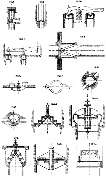
Larger plate.
1648. Double-beat valve, with sunk seating.
1649. Common D slide valve, with three ports.
1650. Duplex or double D slide.
1651. Another form, partly in equilibrium.
1652. Equilibrium slide valve, with circular packed trunk on back, of area sufficient to balance the face area of valve.
1653. Similar result obtained by a piston and link.
1654. Equilibrium piston valve employed in lieu of the slide valve. A steam pipe, B B exhaust.
1655. Gridiron slide valve.
1656. Common plate slide valve or sluice, used for blast pipes.
1657. Floating ball valve, for automatic discharge of air from water mains.
1658. Ordinary double-faced sluice valve, lifts clear of the water way.
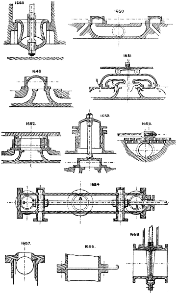
Larger plate.
1659. Single face sluice valve, for sewage water, &c.
1660. Flap sluice valve. Tidal outlet valve.
1661. Diaphragm valve.
1662. Oscillating disc valve, for gas.
1663. Large 3 or 4-way plug cock.
1664. Finger valve, closed by a spring.
1665. Taper cone valve, for gradually closing an outlet.
1666. Dome valve, used for hot blast, hot gases, &c. This form retains its shape when heated, expanding evenly.
1667. Common floating ball tap.
1668. Three-way air valve.
1669. Duplex slide, used to close a number of openings at once.
1670. West’s spiral valve, with indiarubber cord which expands and contracts over a spiral perforated groove.
1671. Dennis’ self-lifting valve. The valve is kept to its seat by the pressure being admitted on to its back through small hole A; when the larger hole B is opened by the spindle the back pressure is relieved and the valve lifted by the pressure below its conical underside.
1672. Common cone plug.
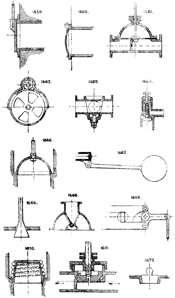
Larger plate.
1673. Equilibrium plug or cylindrical valve, double ported.
1674. Another form of self-lifting valve. See No. 1671 for description.
1675. Compound flap valve.
1676. Indiarubber pump valve.
1677. Venetian shutter or compound butterfly valve.
1678. Bye pass used to allow a small flow when the main valve is shut off. Used also to equalise pressure on both sides of a large valve to enable it to open easily.
1679. Bell and hopper, or cup and cone; used for blast furnaces, coke ovens, and gas generators.
1680. Cup valve and suspended weight.
1681. Four-way valve for hot water pipes, &c.
1682. Oscillating valve.
1683. Gas purifier centre valve, for four purifiers; to work one purifier off and three on, or all four on at once. It is similar in plan to No. 1684, but has an additional top valve which allows the gas to pass into the fourth purifier; the top valve has an independent sleeve and lever motion.
1684. Gas purifier centre valve, employed to deliver and discharge gas into and out of any one, two, or three out of four purifiers. The motion of the gas is shown by the arrows.
1685. Conical grating valve with radial slots, opened or closed by revolving motion.
Section 90.—WATER WHEELS AND TURBINES.
1686. Simple undershot wheel.
1687. Breast wheel.
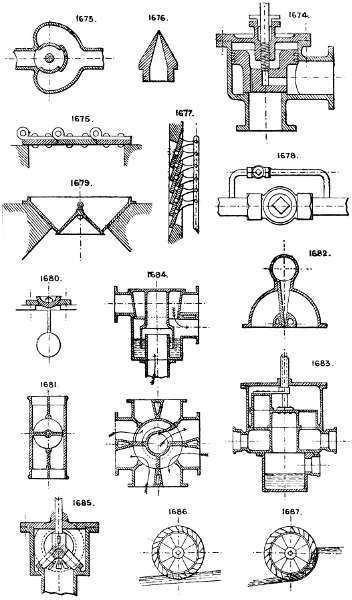
Larger plate.
1688. High breast wheel.
1689. Overshot wheel.
1690. Return overshot wheel.
1691. Internal feed re-action wheel.
1692. Sunk wheel, driven by air: may be used as a meter for gas or air.
1693. Current wheel, driven by tidal or river current.
1694. Flutter wheel, with high fall.
1695. Horizontal wheel.
1696. Re-action wheel, the oldest form of turbine.
1697. Engel’s diagonal wheel.
1698. Scoop wheel for raising water. See also No. 1024.
1699. Wheel, with internal buckets and feed.
Note that most of these may be reversed and made into water raising machines, as No. 1698.
1700 to 1703. Sections of various forms of buckets in wood and iron. No. 1703 is a ventilated bucket which allows air to escape as the water enters.
For governing speed of water wheels and turbines, see Section 41.
1704. Fourneyron’s turbine, outward flow; the outer vanes are fixed, the inner ones revolve with the shaft.
1705. Jonval’s turbine, downward flow; either the upper or lower set is fixed.
1706. Swain’s turbine, inward and downward flow, with inward curved vanes or flumes.
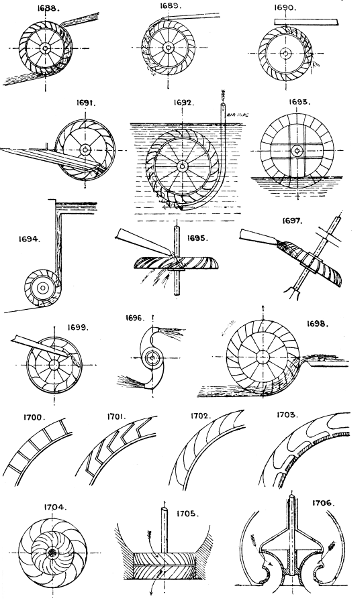
Larger plate.
1707. Leffel’s turbine, inward and downward flow; has one outer ring of fixed vanes and two inner sets revolving, but having different angles of flow.
1708. Undershot jet wheel for high pressure water.
Many other forms of turbines are extant, but are mostly modifications of the above types. The best types have means of varying the angle of the vanes and areas of passages to suit varying quantities of water.
Section 91.—WHEELS IN SEGMENTS.
1709. Heavy gearing for rolling mills, &c., with dovetailed joints wedged and packed.
1710. Wheel cast in sectors bolted together.
1711. Bevil wheel in halves.
1712. Wheel with rim in segments bolted together, and provided with bored and cottered sockets for arms in both rim and boss.
1713. Fly wheel rim, cottered and dowelled together.
1714. Arms and boss cast in one: the rim in segments, bolted together and to the arms.
1715. Tension wheel. The tie spokes are sometimes arranged in two sets at a slight angle to each other to prevent the rim turning without the boss. Bicycle wheels are of this class.