PART I. SECTIONS 1-106. (continued 3)
Reading edition
1716. Wrought-iron wheel, with cast boss.
1717. Wrought-iron wheel, with cast boss.
1718. Rim in segments bolted together, wood arms and cast boss, with sockets to receive arms; this type is much used for water wheels.
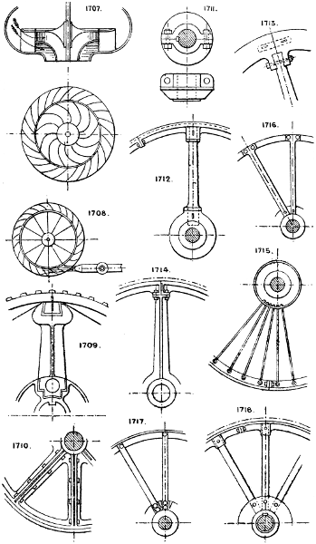
Larger plate.
1719. Railway wheel: boss of cast iron with wrought-iron arms cast in. The rim is of rolled iron or steel riveted on. There are numerous methods of fastening the tyres to arms, detailed in the Engineer, July 23rd, 1880.
1720. Spring rim split pulley.
1721. Segment fly-wheel, with long radial bolts to secure the rim, arms, and boss together.
1722. Large centre boss, with rim segments bolted to it.
1723. Wheel in halves; the boss is held together by two bolts acting as cotters.
Section 92.—WEIGHING, MEASURING, INDICATING PRESSURES, etc.
1724. Weighing by a beam with equal arms. Weights A = package B.
1725. Weighing by a beam with unequal arms. Weight A constant; leverage of ditto variable by shifting it along the graduated arm of lever.
1726. Graduated measuring vessel.
1727. Similar principle applied by compound levers with unequal arms. The table is supported on four points on the arms of levers loosely jointed together in the centre; one lever is extended and coupled by a rod to a graduated lever with sliding weight. Knife edges are used for bearings for all weighing machines by leverage. See No. 958. This construction is the basis of most of the ordinary weighing machines in use.
1728. Duckham’s patent hydraulic weighing machine. The article to be weighed is suspended from the hook, and exerts a pressure on the ram. The corresponding pressure on the liquid (usually oil or glycerine) is indicated on the pressure gauge, which is graduated to show the weight.
1729. Spring balance.
1730. Appliance for indicating depth of water in a cistern by an air bell and pipe connected to a U water gauge. The pressure on the air in the bell varies with the depth or head of water above it, and is indicated on the gauge. A modification of this is employed for sounding at sea.
Weights of substances may be ascertained by their displacement in water or mercury, or by supporting the weighing scale on a free piston resting on an ascertained area of water or mercury, the pressure produced being indicated by a gauge.
1731. Micrometer gauge.
1732. Radial arm weighing machine.
1733. Small weighing device, depending upon the angle the card assumes in respect of the vertical pointer, which is on a free pivot.
1734. Automatic measuring or weighing device. The material fills one compartment until it overbalances, when it falls and empties itself; the material then fills the other compartment, and so on.
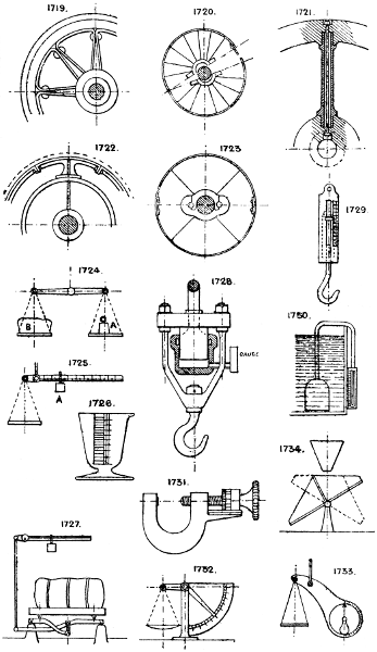
Larger plate.
1735. Wet gas meter. The gas enters at the centre, and as the compartments fill they rise out of the water, the gas being discharged at the outer ports into the casing.
1736. Measuring wheel.
1737. Measuring wheel.
1738. Double slide measurer.
1739. Automatic tipping scale. When full, to equal the weight, it falls and tips by striking a fixed stop; the scale then turns over and returns to its position, and is refilled.
1740. An ordinary piston and cylinder are often employed to measure liquids, and fitted with a reversing valve on the same principle as Nos. 1026, 1027, and 1741. See also note to Sec. 93.
Most of the rotary devices (see Section 75) have been employed as meters for liquids and gases. See No. 1692.
Dry gas meters usually employ an expanding bellows, or light piston, with a self-reversing valve, similar to Nos. 1299 and 1026. See also Section 44.
Section 93.—WATER-PRESSURE ENGINES.
See also Section 56.
Hydraulic ram. See No. 1025.
Robinet. See No. 1026.
Two- or three-cylinder engines, with slide valves operated either by eccentrics as in the steam engine, or by the oscillation of the cylinder. The slide valves have no lap or lead; there is no cushioning except what is given by an air vessel on the supply pipe. Three-cylinder engines are usually made single acting with rams. See No. 1743.
1741. Single cylinder engines. These must have the slide or other distributing valve reversed by pistons A, A, operated by the pressure of the supply water. This is usually done by an auxiliary valve B, reversed by the main piston rod C. This valve admits the pressure water to the pistons A, A, which reverse the main slide valve. See No. 1506. See note below.
1742. Mode of working an underground pumping engine by water cylinders above ground, connected to those below by pipes A, A. B is the suction, C the delivery.
1743. One, two, or three cylinder water engine. The ports are in the segmental base of the cylinder, have no lap, and are opened and closed by the oscillation of the cylinder.
1744. Circular oscillating cylinder, in a case which opens and closes its ports by its own oscillation.
In lieu of the weighted lever valve gear for single cylinder water pressure engines, the engine may be arranged to compress a spring during the stroke, which at the end of the stroke shall be released, and by its expansion reverse the valve.
Section 94.—WASHING.
1745. Cylindrical revolving screen washer, for roots, &c.
1746. Tub and paddle washer.
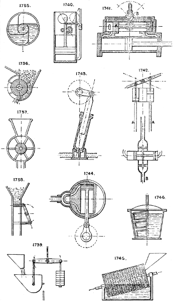
Larger plate.
1747. Coal washer. The water is kept in motion up and down through the screen A by a cylinder and piston B; the mud sinks to C and the washed coal passes over to D. Both are removed continuously by elevators or worms. See Section 57.
For washing ores sloping screens either plain or perforated are often used, a stream of water being kept flowing over the ore, which is kept in motion. See Nos. 1266 and 477, also Cylindrical Revolving Screens, as No. 1262.
1748. Cylindrical perforated drum, with internal fixed spiral flange which causes the material to travel at a fixed rate of motion. The cylinder may be revolved in a water trough as No. 1745, or water may be fed in with the material and the casing be unperforated.
1749. A contrivance to keep a continuous circulation in a boiling tub or copper in which clothes, &c., are washed. The hot water from the bottom rises up the tin tube, and is discharged on the surface.
1750. Corrugated rollers washing device, for fabrics.
1751. Water trough and dipping band, for washing cloths, wool, paper, &c.
Domestic washers comprise, besides the ordinary tub and dolly, washing boards, having corrugated surfaces; rocking and revolving boxes, having a churn-like motion. Brushes also are sometimes used.
Section 95.—WINDMILLS AND FEATHERING WHEELS.
1752. Feathering paddle wheel. Each float has a bracket and pin at back, with connecting rod to a common eccentric (fixed), through which the shaft revolves.
1753. Spiral vane or cowl, for chimney top. Used to drive a vertical worm inside the chimney cap to maintain an upward draught, by employing the wind as a motive power.
1754. Windmill sails, with angular adjustment by a sliding device on the shaft.
1755. Feathering horizontal windmill. Each float is hinged a little out of centre to the arms, so that the pressure of wind (see arrow) turns the floats to the positions in the sketch as they revolve.
1756. Hollow semi-spherical cup windmill or motor.
1757. Wind motor, with curved vanes. These last two revolve in the direction of the arrows, because the wind has more hold upon the hollow sides of the cups and vanes than on the convex side.
1758. Self-feathering wind wheel.
1759. Spiral wind wheel.
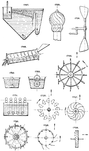
Larger plate.
Section 96.—WINDING APPARATUS.
1760. Barrel or drum, for wire, &c.
1761. Winding barrel, for cranes, winches, &c.
1762. Fusee barrel. See No. 1602.
1763. Grooved barrel, for chain. Prevents the chain riding as it coils.
1764. Hexagon frame winder, for yarn, &c.
1765. Spool.
1766. Card winder.
1767 & 1768. Bobbins. There are a great many patterns in use for various trades.
1769. Appliance for winding bobbins of cotton, and other machinery. The bobbin is stationary and the flyer revolves, the thread passing up its centre and down one arm through the eye, which has an up and down feed motion to wind the thread on evenly.
1770. Mode of feeding the thread on to the spindles to cause it to coil evenly by an oscillating arm and pin over which the thread passes.
1771. Drum, for flat rope or chain wound upon itself.
For winding engines and winches, see Nos. 1222 to 1226.
See also Rope Gear, Section 66.
Section 97.—HANDLES, &c., FOR VARIOUS PURPOSES.
1772. Knob handle.
1773. Loop handle, hinged.
1774. Loop handle, fixed.
1775. T handle.
1776. Plain handle.
1777. Sash lift or drawer handle.
1778. Hand bar.
1779. Swing door handle.
1780. Sunk or flush loop handle.
1781. Hinged lifting levers.
1782. Bent handle, for radial motion.
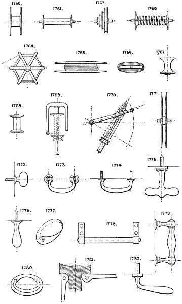
Larger plate.
1783. Hand wheel.
1784. Cranked T handle.
1785. Capstan wheel.
1786. Bow or lifting handle, for ladles, buckets, &c.
1787. T bar handle, for two hands.
1788. Cross hand lever, four, six, or eight arms.
1789. Loop handle, sometimes cast into a casting.
1790. Ring handle.
1791. Double bar pushing handles.
1792. Bent handle, for radial motion.
1793. Weighted handle.
1794. Vice handle, with sliding lever bar.
1795. Hand bar, with forked lever attachment for pumps, &c.
1796. S lever double cranked handle.
1797. Stirrup handle.
1798. T lifting handle or key, for opening flush doors or manhole covers.
1799. Thumb screw head.
1800. Straight handle, with suspending eye.
1801. Capstan wheel, for screw gear.
1802. Ventilated twisted handle.
1803 & 1804. Loop handles.
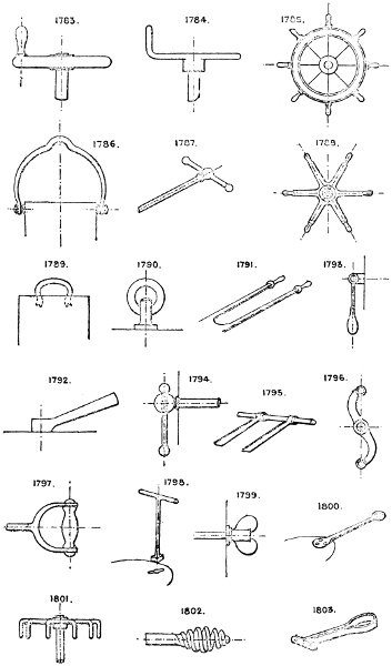
Larger plate.
1805. Spring lock lever handle.
1806. “Coffee pot” handle.
See also Section 48.
Section 98.—APPARATUS FOR DRAWING CURVES.
See Gearing, Section 40; Ellipsograph, Section 34.
1807. Cyclograph, for describing arcs, the chord and versed sine being given. Fix pins at A and B, fasten together at C two slips of wood, hold the pencil at D, and move the slips round, keeping them against the pins. See also No. 11.
1808. Hyperbolagraph. Height and focus are given as for 1809, and string fixed to B, and focus A; the arm is pivoted at C, and the pencil used as described for No. 1809.
1809. Parabolagraph. The height of parabolic curve H and focus A are given. A string is fastened to end of set square at B, reaching to C, and the other end fixed to a pin in the focus A. A pencil held in the loop and kept against edge of set square as it is moved to left or right will describe the parabolic curve.
1810. Cycloidograph, describes the hypo- or epi-cycloid. A modification of this is used to draw the curves of the teeth of wheels.
Pentagraph, for reducing or enlarging outline drawings, No. 1924.
Helicograph, to describe a regular helix by a central fixed bevil wheel which drives the radial bevil wheel screw and scribing pencil, No. 1925.
A simple helicograph, with radial screw and roller nut, which travels along the screw as the apparatus is revolved on its centre pin, No. 1926.
Section 99.—MATERIALS EMPLOYED IN CONSTRUCTION
The following memoranda relate only to such materials as are required in connection with machinery or mechanical constructions, and are intended to supply particulars of the dimensions of the manufactured or raw material, giving the sections manufactured and the limits as to size available for incorporation in any design under consideration.
Rolled iron and steel bars are manufactured as below:—
1811. Rounds, from 3⁄16″ to 73⁄4″ diameter, and up to 18′ long.
1812. Squares, from 3⁄16″ to 6″ square, and up to 18′ long.
1813. Flats, from 1⁄2″ to 14″ wide, and up to 18′ long.
1814, 1815, 1816, 1817, 1818, & 1819. L iron sections are made from 3⁄4″ × 3⁄4″ up to 14″ × 33⁄4″, or to 121⁄2″ united inches, with equal or unequal flanges, and up to 30′ long; but the acute, obtuse, and round angled sections are not usually stocked.
1820 & 1821. T irons, from 1″ × 1″ up to 12 united inches, or to 9″ × 4″, and up to 30′ long.
1822. Rolled girder iron, from 3″ deep to 20″ deep × 10″ flanges, and to 36′ long, in hundreds of sections.
1823. Zore girders, from 3″ to 8″ deep, and to 24′ long.
1824. Channel iron, from 3⁄4″ to 12″ wide, and to 25′ long.
1825. Convex iron, from 1″ to 6″ wide, and up to 20′ long.
1826. Cope iron, from 1″ to 4″ wide, and to 20′ long.
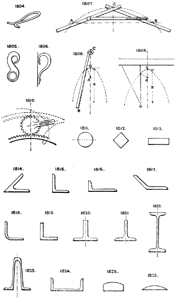
Larger plate.
1827. Half-round iron, from 1⁄2″ to 4″ wide, and to 20′ long.
1828. Funnel ring iron, from 31⁄2″ × 3⁄16″ to 8″ × 9⁄16″ wide, and up to 18′ long.
1829. Jackstay iron.
1830. Hollow cope iron.
1831, 1832, & 1838. Rail sections (see Section 73), usually made in 18′ to 30′ lengths, and numerous sections of from 22 lbs. to 84 lbs. per yard.
1833. Bulb L iron.
1834. Deck beam or bulb T iron, up to 16″ × 6″.
1835. Bulb L iron, up to 10″ × 4″.
1836. Bulb iron, to 13″ wide.
1837. Pile iron.
1839, 1840, & 1841. Flush tram rails, 18′ to 30′ long.
1842, 1843, & 1849. Fire bar iron.
1844. Double L iron, 1⁄2″ × 1″ × 1⁄2″ to 5″ × 5″ × 1⁄2″.
1845. Cross iron.
1846, 1847, & 1853. Sash bar iron. Hundreds of special sections are manufactured.
1848. Bevil edge iron.
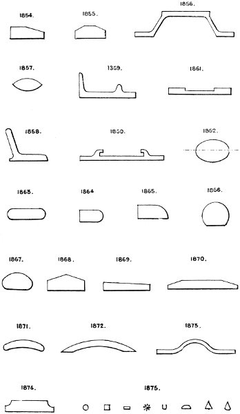
1850. Octagon bar iron.
1851. Hexagon bar iron.
1852. Tyre iron, made in many sections. See note to No. 1719.
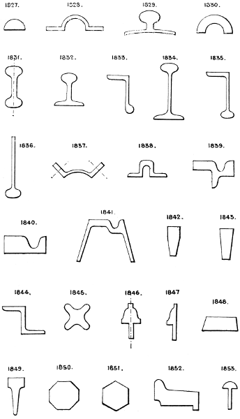
Larger plate.
1855. Bevilled flat iron.
1856. Trough iron. Used for bridge flooring, fire-proof floors, &c.
1857. Double convex iron.
1858 & 1859. Tramplate iron.
1860 & 1861. Chair or sleeper iron.
1862. Oval iron.
1863, 1864, & 1865. Round edged flats.
1866. Segment round iron.
1867. Round edged convex iron.
1868. Bevilled flat iron.
1869. Bevil edge flat iron.
1870. Bevilled flat iron.
1871. Round edged hollow convex iron.
1872. Taper edged hollow convex iron.
1873. Boiler tube expansion ring iron.
1874. Moulded flat bar.
In addition to the above, iron ornamental mouldings are rolled with moulded and relief ornaments in bars, from 5⁄8″ to 23⁄4″ wide, and up to 16′ or 18′ long. Also plain mouldings similar in sections to those used in joinery.
Plates (iron and steel) are manufactured from 1⁄8″ to 3⁄4″ thick ordinary. Thicker plates are rolled to order up to 20″ thick.
Stocked sizes of ordinary plates are 4′ × 2′ up to 14′ × 4′ 6″.
Strips from 7″ to 22″ wide, and up to 30′ long.
Chequered plates, with diamond, oval or square recessed patterns, are made 6′ × 2′ up to 8′ × 3′ 6″.
Sheets, plain, in thicknesses from No. 10 w.g. to No. 36 w.g., and from 6′ × 2′ to 10′ × 4′.
Corrugated sheets, plain or galvanised, from No. 16 to No. 26 w.g., and from 6′ × 2′ to 9′ × 2′.
Tinned sheets, same as above.
Cold rolled sheets, same as above.
Planished sheets, same as above.
Lead-coated sheets, same as above.
Tin plates, terne plates, 14″ × 20″, 17″ × 121⁄2″, 15″ × 11″, 14″ × 10″, 24″ × 20″, 28″ × 10″, 28″ × 20″.
Hoops, from 5⁄8″ to 7″ wide, and from No. 8 to No. 24 w.g.
1875. Wire; sections manufactured in hard iron, soft iron, soft steel, hard steel, tempered steel, piano wire, covered wire (wound with either cotton, silk, guttapercha, flax, &c.), or copper wire. Also brass, copper, lead, zinc, and other metal wire, hard or soft; tinned iron wire, galvanised iron wire, tinned brass wire, coppered iron wire, lead-coated iron wire.
Larger plate.
Pipes (see Section 57) and tubes of wrought iron, either butt or lap welded, or solid drawn, are made in four qualities or strengths:—1. Gas tube; 2. Steam or water tube; 3. Boiler flue tube; 4. Hydraulic tube. These are manufactured from 1⁄4″ to 3″ internal diameters; boiler flue tubes to 9″ diameter, but much larger sizes can be made to order.
Solid drawn steel tubes are made up to 10″ diameter; larger sizes are made to order.
Special steel or wrought iron pipes, flanged with L iron, are made up to 4′ diameter with welded joints, and welded steel or wrought iron socket and spigot pipes up to 24″ diameter.
Cast iron pipes are made in the following strengths:—Rainwater pipes, hot-water pipes, gas mains, water mains, hydraulic mains for high pressure, and the thicknesses of metal vary according to the pressures. Diameters from 11⁄2″ up to 4′, and lengths usually 6′ and 9′. See Section 57.
Castings are made in cast iron of various mixtures, according to strength, toughness, or hardness required, and of any weight up to 20 tons. Chilled iron castings are made for hard wear, as in crusher rolls, &c., but cannot be machined; they are usually ground smooth by a grindstone or emery wheel.
Steel castings are made in either Bessemer, Siemens-Martin, Thomas-Gilchrist, or in crucible steel, the latter being most relied upon. They require annealing to soften them sufficiently for machining, are almost invariably “blown” or honeycombed, and rarely homogeneous, or twice alike from the same pattern or cast.
Wrought-iron castings, Mitis metal, &c., are also obtainable, but malleable cast iron castings are most relied upon for toughness, the process having now attained great perfection, but is not applicable to very thick castings.
Pressed iron on steel forgings of simple forms are now obtainable at low prices.
Forgings in wrought iron and steel can now be made to almost any size, shape, and weight, and are replacing many structures formerly made of cast iron or built up.
Other metals employed are copper, brass, tin, zinc, phosphor-bronze, lead, antimony, bismuth, pewter, Muntz metal, aluminium, sodium, potassium, platinum, gold, silver, nickel, and a great variety of the bronzes, which are valuable compounds varying in tenacity and hardness from the hardest steel to that of soft copper. Most of the above are manufactured into wire, sheets, tubes, rods, &c., and can in addition be cast into any form from a crucible. Copper can be forged but not welded; joints in it are generally brazed or soldered.
Other materials employed comprise—
Timber. Yellow, white, and red pine in logs, deals, and battens; logs, up to about 3′ diameter by 35′ to 40′ long; deals, 9″, 10″, and 11″ wide, and from 11⁄2″ to 4″ thick—a few wide deals are imported up to 22″ wide—spruce and fir, sycamore, pear tree, willow, poplar, &c. The following table gives a list of woods and their applications:—
TABULAR STATEMENT OF THE WOODS COMMONLY IN USE IN GREAT BRITAIN.
For Building.
Ship-building.—Cedars, deals, elms, firs, larches, locust, oaks, &c., &c.
Wet works, as piles, foundations, &c.—Alder, beech, elm, oak, plane-tree, white cedar.
House carpentry.—Deals, oaks, pines, sweet chestnut.
For Machinery and Mill-work.
Frames, &c.—Ash, beech, birch, deals, elm, mahogany, oak, pines.
Rollers, &c.—Box, lignum vitæ, mahogany.
Teeth of wheels, &c.—Crab-tree, hornbeam, locust.
Foundry patterns.—Alder, deal, mahogany, pine.
For Turnery.
Common wood for toys (softest).—Alder, beech (small), birch (small), sallow, willow.
Best woods for Tunbridge ware.—Holly, horse chestnut, sycamore (white woods); apple-tree, pear-tree, plum-tree (brown woods).
Hardest English woods.—Beech (large), box, elm, oak, walnut.
For Furniture.
Common furniture and inside works.—Beech, birch, cedars, cherry-tree, deal, pines.
Best furniture.—Amboyna, black ebony, cherry-tree, Coromandel, mahogany, maple, oak (various kinds), rose-wood, satin-wood, sandal-wood, sweet chestnut, sweet cedar, tulip-wood, walnut, zebra-wood.
Foreign hard woods, several of which are only used for ornamental turnery.—
1. Amboyna. 13. Greenheart. 25. Peruvian.
2. Beef-wood. 14. Grenadillo. 26. Princes-wood.
3. Black Bot. B. wood. 15. Iron-wood. 27. Purple-wood.
4. Black ebony. 16. King-wood. 28. Red sanders.
5. Box-wood. 17. Lignum vitæ. 29. Rosetta.
6. Brazil-wood. 18. Locust. 30. Rose-wood.
7. Braziletto. 19. Mahogany. 31. Sandal-wood.
8. Bullet-wood. 20. Maple. 32. Satin-wood.
9. Cam-wood. 21. Mustaiba. 33. Snake-wood.
10. Cocoa-wood. 22. Olive-tree & root. 34. Tulip-wood.
11. Coromandel. 23. Palmyra. 35. Yacca-wood.
12. Green ebony. 24. Partridge-wood. 36. Zebra-wood.
Nos. 3, 8, 16, 33, and 34 are frequently scarce.
Nos. 3, 5, 8, 9, 10 are generally close, hard, even tinted, and the more proper for eccentric turning, but others may also be employed.
Nos. 4, 5, 10, 12, 14, 17, 18, 19, 30, 32 are generally abundant and extensively used. All the woods may be used for plain turning.
Miscellaneous Properties.
Elasticity.—Ash, hazel, hickory, lance-wood, sweet chestnut (small), snake-wood, yew.
Inelasticity and toughness.—Beech, elm, lignum vitæ, oak, walnut.
Even grain, proper for carving.—Lime-tree, pear-tree, pine.
Durability in dry works.—Cedar, oak, poplar, sweet chestnut, yellow deal.
Colouring matter (red dyes).—Brazil, braziletto, cam-wood, log-wood Nicaragua, red sanders, sapan-wood.
Colouring matter (green dye).—Green ebony.
Colouring matter (yellow dyes).—Fustic, zantes.
Scent.—Camphor wood, cedar, rose-wood, sandal-wood, satin-wood, sassafras.
Indiarubber, manufactured into sheets, with or without canvas insertion of single, double, or treble thickness, up to 36″ wide and to 1⁄2″ thick; cord to 1″ diameter; tubes, plain, or with canvas insertion or wire coiled inside or outside, from 1⁄4″ to 4″ bore, usually in 30′ and 60′ lengths. Washers, rings, rollers, strips, belts, and moulded articles of every form.
Guttapercha is manufactured into similar articles.
Leather. Most of the varieties are manufactured from the skins of oxen, sheep, goats, deer, horses, dogs, hogs, and seals, and the larger skins are divided into butts, shoulders, cheeks, and bellies, the dimensions depending of course upon the size of the animals. Ox hides are the largest and kid skins the smallest in general use.
For mechanical purposes ox hide, raw or tanned, is chiefly used, as for valves, seatings, belts, piston leathers, &c. Sheep skins can be obtained either strained, half-strained, or unstrained; the first are hard and comparatively stiff, the last-named soft and pliable as cloth. Other soft varieties are goats’ skins and chamois leather. There are many imitations of leather, but they are rarely employed in mechanical constructions.
Vulcanised fibre is often used for similar purposes to leather, as for valves, seatings, joints, &c. It is made in two varieties, medium and hard, and in sheets up to 1″ thick.
Ebonite. A hard, black, horny substance, moulded into any required shape.
Papier mâché. Solid paper, moulded from pulp into any required form.
Asbestos, in sheets, cord, packing of various sections, loose fibre, millboard, &c.
Ivory, from tusks and teeth.
Bone.
Vegetable ivory; nuts about the size of eggs.
Packings for glands, &c., are made of cotton, hemp, and other fibres, asbestos, indiarubber, &c., in round, square, and other sections.
Section 100.—HEATING APPARATUS.
For general purposes this comprises Furnaces, Stoves, Ranges, Ovens, Boilers (see Section 6), Hot-blast, Steam-heated Vessels, Gas Jets, &c., most of which are tolerably well known and in common use.
For special purposes in connection with machinery various heating devices are required, of which steam and gas are those most universally used. Steam tubes or coils may be carried through any fixed or movable part of a machine. Steam-heated surfaces, such as tables, pans, chambers, &c., steam-jacketed cylinders, and similar contrivances, are much used. Gas jets from perforated tubes, which may be shaped to any required position, are also convenient for dry heat and higher temperatures than can be obtained from steam.
Hot irons are sometimes used, shaped to fit a cavity, but of course require to be replaced periodically.
Hot water in pipes or jackets, and hot air in flues are common appliances for warming and drying; with the former its circulation must be provided for, and with the latter, either a forced draught or an upward inclination given to the flues to maintain circulation.
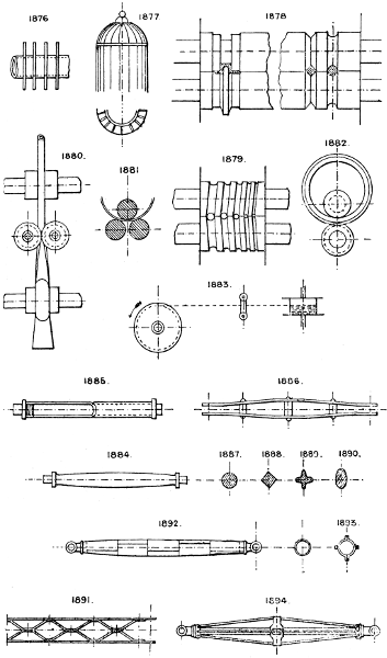
1876. Gill pipes for radiating the beat of steam or hot water.
1877. Gill stove, on similar principle, presents an extensive surface in contact with the air for radiation of heat.
Section 101.—DRAWING AND ROLLING METALS, &c.
1878. Rolls for bar iron, grooved to suit the section required, one-half the groove being usually in each roll, and the size and shape of the grooves are graduated down from that of the square billet to the finished bar.
1879. Grooved rolls for producing a tapered bar.
1880. Rollers for turning up and welding tubes from a flat strip.
1881. Bending rollers.
1882. Rolls for solid tyres, without a weld.
1883. Wire drawing apparatus.
For grips for drawing wire, &c., see Nos. 505, 518. Laths of various sections are drawn through suitable steel dies by a draw bench; the end of the lath is held by a grip tongs and the lath drawn forcibly through the dies (using a lubricant) and afterwards straightened. Rolling does not answer for this kind of work.
The drawing frame used for cotton and other fibres has two, three, or more pairs of rollers; the lower rollers are grooved longitudinally and the upper ones weighted and covered with leather, the lower ones being geared together to drive at proportionate speeds, so that in passing through, the material is stretched between each pair of rollers, the object being to extend and lay all the fibres parallel.
For drawing lead pipes, see No. 1183. Earthenware pipes are made by a similar process.
Section 102.—STRUTS AND TIES.
1884. Ordinary solid swelled distance rod with collars, used for compressive strains.
1885. Similar strut, but formed of tube with end collars screwed in.
1886. Double flat-bar cambered strut, stiffened by distance pieces and bolts.
1887, 1888, 1889, & 1890. Sections of varieties of the foregoing.
1891. Braced strut; usually of flat bars on edge, riveted together at the intersections.
1892. Tubular swelled strut, of plate iron, used for masts, sheer legs, crane jibs, &c.
1893. Built up strut, from segmental bars.
1894. Trussed strut; the trussing is 90° apart, but may be at any angle; the central bar of course takes the actual thrust, and the truss rods keep it from bending or buckling. See also Nos. 295 to 300, 320.
Ties, for tensile strain only are usually of round iron, flat or other simple section, tube, or even chain, rope, or wire.
Larger plate.
Section 103.—MARINE ENGINES (TYPES OF).
Many varieties will be found illustrated under Section 32. The following are modern types:—
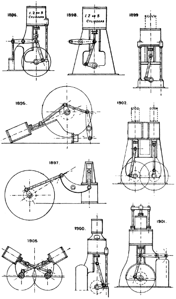
1895. Diagonal paddle engines, for light draught vessels. May of course be either of two or three cylinder type and either high pressure or compound.
1896. One of the most favourite types of vertical overhead cylinder screw engines, with half standards and distance rods, one, two or three cylinders, simple or compound. The condenser is usually in the back standards and the pumps behind. Simplicity and accessibility are its chief advantages.
1897. Stern wheel, side lever engines, not often required in practice. The ordinary construction of horizontal engines usually accommodates itself for stern wheel driving. See Nos. 575 to 579, &c.
1898. Double standard vertical overhead cylinder screw engines, the type commonly adopted for the heavier class of vessels, and frequently made for triple expansion. It is of very rigid construction, but not quite so convenient for accessibility to the working parts as No. 1896. The condenser and pumps are at one side, built into the standard, and the engines are handled from the opposite side or from an elevated platform.
1899. Overhead cylinder and distance rod type, the lightest and simplest form in use for small engines. Every part is easily seen and got at, and the top weight is reduced to a minimum.
1900. Is a variety of No. 1896, with tandem cylinders and two cranks for triple expansion.
1901. Is also a variety of No. 1898, with tandem cylinders for triple expansion. In this plan the intermediate stuffing box is got rid of by using two piston rods to the lower cylinder, coupled to the piston rod of the upper or high-pressure cylinder by a crosshead.
1902. Compound overhead standard engines, for twin screws.
1903. Diagonal twin screw engines.
Larger plate.
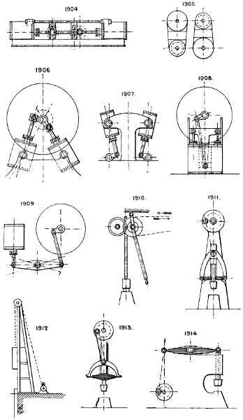
1904. Horizontal twin screw engines.
1905. Plan of cylinders as usually employed for No. 1902.
1906. Oscillating paddle engines, sometimes made with cylinders at 90° apart and a single crank, as No. 564.
1907. Overhead oscillating twin screw engines.
1908. Annular cylinder paddle engines.
1909. Overhead cylinder side-lever paddle engines.
In addition to the above some special types are occasionally employed, as the Willan’s three-cylinder plan for screw engines. See No. 592, also varieties of No. 593, high-speed types.
Section 104.—STRIKING AND HAMMERING: IMPACT.
The ordinary appliances for these purposes comprise hammers of all kinds and anvils or blocks of all shapes to suit the work, rammers and mallets of wood. The steam hammer being the machine almost invariably used, is too well known to need illustration. It is made with single or double standards, and though differing somewhat in details is practically the same machine wherever manufactured.
The following are apparatus employed for particular cases, and not so well known.
1910. The drop hammer, for power. The grip pulleys are put in gear by the hand lever to raise the hammer and shaft: it is sometimes worked by hand by a simple cord and pulley.
1911. Dead blow power hammer. The crescent-shaped crosshead bar has a positive motion from the crank pin, but the hammer head is attached to it by strong horizontal springs, and therefore has some little play above and below a horizontal line.
1912. The pile engine and monkey. The latter is generally raised by a hand or power winch, but a multiplying gear steam or hydraulic cylinder has been employed.
1913. Another form of dead blow power hammer, but with a straight laminated plate spring, to which the hammer head is fixed.
1914. Another type of spring power hammer.
Larger plate.
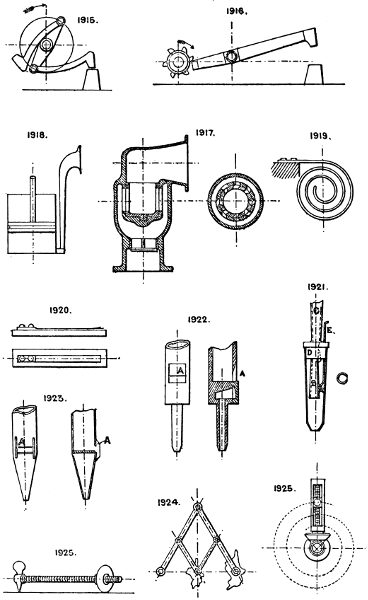
1915. Revolving centrifugal rapid blow hammer.
1916. The old-fashioned tilt hammer, still in use in many places, especially where water-power is employed.
For stamps, &c., see Nos. 250 & 271.
Besides the foregoing there is the gas hammer of Messrs. Tangye, the pneumatic hammer, and a variety of power hammers with variable stroke. See No. 1606.
Section 105.—SOUND.
Instruments for the production of sound are scarcely within the province of the mechanical engineer, but of late years several of them have been employed in connection with mechanical means for producing sound—for fog signals, whistling, and other forms of sound signalling. Musical sounds are produced by vibration of air from wind, string, or reed instruments. In wind instruments the vibration is produced by the lips and modified by the shape and length of the tube. Strings are either bowed, as in the fiddle, struck, as in the piano, or fingered, as in the harp. Reeds are springs vibrated by a current of air. In the harmonium and concertina class of instruments there are no tubes or pipes added to the reeds to modify the sounds produced; but in the organ pipe the reeds have pipes added which greatly augment and qualify the sounds. Other special sound-producing instruments are illustrated here.
1917. The Siren, or steam turbine whistle, the loudest instrument known, consists of a slotted cylindrical drum revolving inside a fixed drum; the slots are angular (see plan), so that the rush of steam revolves the inner loose drum rapidly and the sound is directed by the trumpet-shaped hood. A pair of slotted discs is also sometimes used for the same purpose instead of the slotted drums.
1918. Mechanical fog-horn; ordinary bellows are often used to supply the blast.
1919. Iron gong, struck with a muffled hammer.
1920. Harmonium reeds, or free reeds; the tongue covers a slot of same size and shape, and can vibrate into and out of it, but without touching its edges; the gravity of tone or pitch depends on the size and thickness of the tongue.
1921. Organ reed pipe; the tongue A in this case beats, with a rolling contact, upon the reed B, which is tubular, closed at bottom and opening at top into the pipe C, which extends upwards from the block D; E is the tuning wire which regulates the vibrating or free length of the tongue.
1922 & 1923. Wood and metal organ pipes, which are practically large whistles, the vibration of the column of air in the pipe being produced by the wind striking the edge of the lip A.
Steam whistles are bells with a ring-shaped slit below, from which the issuing steam strikes the lower edge of the bell.
Other forms are now made giving a more musical sound, and in some cases a double note, usually an interval of a major third, as C-E, by a modified form of pipe with two lips.
Striking bells of various shapes are extensively used.
Gongs are cheese-shaped metallic hollow suspended vessels, and are struck by a muffled hammer.
Musical sounds are also produced from slips of glass, or chilled iron, glass bells and tumblers, and also from resonant magnetic iron blocks.
1924, 1925, 1926. See Sec. 98.
Larger plate.
Section 106.—DOORS, MANHOLES AND COVERS.
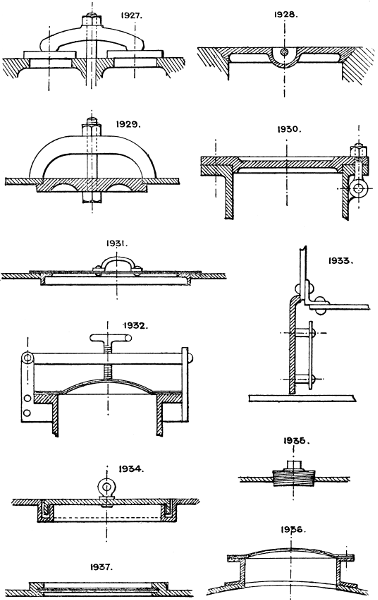
1927. Application of a single crosshead and bolt to close two covers, as in a pump clack-box.
1928. Cone seated cover, with hand-lifting crossbar and recess.
1929. Crosshead and man- or mud-hole, as commonly used for boilers, &c.
1930. Cast-iron manhole and block; T-head bolts are generally used, but also eye-bolts, as in No. 937.
1931. Wrought-iron plate lid, or cover for a tank.
1932. Wrought-iron dished cover, with hinged crossbar and T-screw used largely for gas retorts.
1933. Furnace door; hinged, with inside plate to protect the door from the heat.
1934. Manhole door with water seal, or packed recess to keep back gases, smell, &c.
1935. Screwed plug handhole.
1936. Wrought-iron boiler manhole cover, and block, a special manufacture.
1937. Type of sliding door; can be made airtight by planing the seatings.
Hinged doors are well-known. For hinging, see Section 50. For fastenings, see Locking Devices, Section 49.
See also Nos. 931, 937, 940, 962.
Larger plate.