HISTORY OF TELEGRAPHS,
Reading edition
Employing Electricity in Various Ways for the Transmission of Intelligence.
We presume it will not be uninteresting to the reader, to be presented with an account of the various discoveries, in their chronological order, by which the science of Electricity became known to the world during the seventeenth and eighteenth centuries, and prepared the way for those more magnificent results, which have been made in this the nineteenth century. We will endeavour to make it as brief as is consistent with the importance of the subject, to enable us to mark the succession of discoveries and improvements through two hundred years.
More than any other branch of experimental philosophy, that of electricity had been most neglected, until the seventeenth century. The attractive power of amber is mentioned by Theophrastus and Pliny, and also later by others.
[16] In the year 1600, William Gilbert, a native of Colchester, and a London physician, published a Latin Treatise, De Magnete, in which he relates a variety of electrical experiments. He increased the list of electric bodies and also of substances upon which electrics could act, and noted some of the circumstances relating to their action. His theory of electricity was, however, very imperfect.
In 1630, Nicolaus Cabœus at Terrara, repeated Gilbert’s experiments and made some progress, increasing the list of electrics; as also did Mr. Boyle in the year 1670. He made some discoveries which had escaped the observation of those who preceded him. Cotemporary with Mr. Boyle, Otto Guericke, burgomaster of Magdeburg, (the inventor of the air pump,) made some advances. He constructed a sulphur globe, which he mounted upon an axis, in a wooden frame, and causing it to revolve, at the same time rubbing the globe with his hand, performed a variety of electrical experiments. He was the first to discover, that a body once attracted by an excited electric, was repelled by it, and not again attracted until it had touched some other body. He observed the light and sound produced by the electric fluid, while turning his electrical machine. Dr. Wall about the same time observed the light and sound produced by rubbing pieces of amber with wool, and also experienced a slight shock. He compared the sound and light of the electric fluid so produced, to thunder and lightning.
Sir Isaac Newton also engaged in similar electrical experiments, and gave an account of them to the Royal Society in 1675. Mr. Hauksbee, whose writings are dated 1709, distinguished himself by experiments and discoveries in electrical attraction, and repulsion, and electric light. He constructed an electrical machine, adopting the glass, instead of the sulphur globe. He experimented upon the subtilty and copiousness of the electric light, and likewise upon the sound and shocks produced by the fluid. After the death of Mr. Hauksbee, the science of electricity made but slow progress, and few experiments were made for twenty years. In the year 1728, Mr. Stephen Grey, a pensioner at the Charter House, commenced his experiments with an excited glass tube. He and his friend, Mr. Wheeler, made a great variety of experiments in which they demonstrated, that electricity may be communicated from one body to another, even without being in contact, and in this way, may be conducted to a great distance. Mr. Grey afterwards found, that, by suspending rods of iron by silk or hair lines, and bringing an excited tube under them, sparks might be drawn, and a light perceived at the extremities in the dark. He electrified a boy suspended by hair lines; and communicated electricity to a soap bubble blown from a tobacco pipe. He electrified water, contained in a dish, placed upon a cake of rosin, and also a tube of water. He made some curious experiments upon a small cup of water, over which, at the distance of an inch, he held the excited tube. He observed the water to rise in a conical shape, from which proceeded a light; small particles of water were thrown off from the cone, and the tube moistened.
Mr. Du Fay, intendant of the French king’s gardens, repeated the experiments of Mr. Grey in 1733. He found that by wetting the pack-thread he succeeded better with the experiment of communicating the electric virtue through a line 1256 feet in length. He made the discovery of two kinds of electricity, which he called vitreous and resinous; the former produced by rubbing glass, and the latter from excited sulphur, sealing wax, &c. But this he afterwards gave up as erroneous. Mr. Grey, in 1734, experimented upon iron rods and gave rise to the term metallic conductors. He gave the name pencil of electric light to the stream of electricity, such as is seen to issue from an electric point. He suggested the idea that the electric virtue of the excited tube was similar to that of thunder and lightning, and that it could be accumulated.
Dr. Desaguliers commenced his experiments in 1739. He introduced the term conductor to that body to which the excited tube conveys its electricity. He called bodies in which electricity may be excited by rubbing or heating, electric per se; and non-electric when they receive electricity, and lose it at once upon the approach of another non-electric. In the year 1742, several Germans engaged in this subject. Mr. Boze, a professor at Wittemburg, revives the use of Hauksbee’s globe, instead of using Grey’s glass tube, and added to it a prime conductor. Mr. Winckler substituted a cushion instead of the hand, which had before been employed to excite the globe. Mr. P. Gordon, a Benedictine monk and professor of philosophy at Erford, was the first who used a cylinder instead of a globe. With his electrical machine he conveyed the fluid through wires 200 ells in length and killed small birds. Dr. Ludolf of Berlin, in the year 1744, kindled by electricity the ethereal spirit of Frobenius, by the excited glass tube; the spark proceeding from an iron conductor. Mr. Boze fired gunpowder by electricity. Mr. Gordon contrived the electrical star. Mr. Winckler contrived a wheel to move by the agency of the same fluid. Mr. Boze conveyed electricity from one man to another by a jet of water, when both were placed upon cakes of rosin, six paces apart. Mr. Gordon fired spirits, by a jet of water; and the Germans invented the electrical bells.
Mr. Collinson in 1745 sent to the Library Company of Philadelphia, an account of these experiments, together with a tube, and directions how to use it. Franklin, with some of his friends, immediately engaged in a course of experiments, the results of which are well known. He was enabled to make a number of important discoveries, and to propose theories to account for various phenomena, which have been universally adopted, and which bid fair to endure for ages.
In the year 1745, such was the attention given to the subject of electricity, that experiments upon it were publicly advertised and exhibited for money in Germany and Holland. Dr. Miles, of England, in the same year fired phosphorus by the application of the excited tube itself without the intervention of a conductor. It was at this period that Dr. Watson’s attention was given to this subject. He fired air, made inflammable by a chemical process, and discharged a musket by the electric fluid. He made many experiments, some of which will be described as we proceed.
The year 1745 was made famous by the discovery of the Leyden Phial by Mr. Cuneus a native of Leyden. It appears also to have been discovered by Mr. Von Kleist, dean of the Cathedral in Camin about the same time. By this discovery, electricity could be accumulated and severe shocks given. Mr. Gralath, in 1746, gave a shock to twenty persons at once, and at a considerable distance from the machine. He constructed the electrical battery by charging several phials at once. Mr. Winckler, and also M. Monnier, in France, transmitted the electric fluid through several feet of water as a part of the circuit. M. Nollet, in France, killed birds and fishes by the discharge of the Leyden jars. Improvements were made by Dr. Watson, and others, in the Leyden phial, by coating the inside and outside of it with tin foil. Abbé Nollet gave a shock to 180 of the guards in the king’s presence; and at the grand convent of the Carthusians in Paris, the whole community formed a line of 3600 feet in length, by means of wires between them. The whole company upon the discharge of the phial, gave a sudden spring at the same instant. The French philosophers tried the same experiment through a circuit of persons, holding wires between them, two and a half miles in length. In another experiment the water of the basin in the Tuilleries was made a part of the circuit.
M. Monnier, the younger, to discover the velocity of electricity, discharged the Leyden phial through an iron wire 4000 feet in length, and another 1319 feet, but could not discover the time required for its passage. Dr. Franklin communicated his observations, in a series of letters, to his friend Collinson, the first of which is dated March 28, 1747. In these he shows the power of points in drawing and throwing off the electrical matter. He also made the grand discovery of a plus and minus, or of a positive and negative state of electricity. Shortly after Franklin, from his principles of plus and minus state, explained, in a satisfactory manner, the phenomena of the Leyden phial. Dr. Watson and others in July 18, 1747, conveyed the electric fluid across the Thames at Westminster bridge; the width of the river making a part of the circuit. On the 24th of July, he tried the experiment of forcing the electric fluid to make a circuit with the bend of the river, at the New River at Stoke, Newington. He supposed that the electric fluid would follow the river alone, through its circuitous windings, and return by the wire. He suspected from the result of this experiment, that the ground also conducted the fluid. On the 28th, he proved the fact by supporting a wire 150 feet in length upon baked sticks, using the ground as half of the circuit. On the 5th, of August, he tried another experiment of making the dry ground a part of the circuit for a mile in extent, and found it to conduct equally as well as water. The last experiment was tried at Shooter’s Hill, on the 14th of August of the same year. But one shower of rain had fallen for the five preceding weeks. The wires, two miles in length, were supported upon baked sticks, and the dry ground was used for the return two miles of the circuit. They found the transmission of the electric fluid to be instantaneous. Dr. Watson made many other experiments which we must pass over.
Mr. Ellicott constructed an electrometer for measuring the quantity of electricity. Mr. Maimbury, at Edinburgh, electrified two myrtle trees, during the month of October, 1746, when they put forth small branches and blossoms sooner than other shrubs of the same kind, which had not been electrified. The same experiment was tried upon seeds, sowed in garden pots with the same success. Mr. Jallabert, Mr. Boze and the Abbé Menon principal of the College of Bueil, at Angers, tried the same experiments upon plants, by electrifying bottles in which they were growing. He proved that electrified plants always grew faster, and had finer stems, leaves and flowers than those which were not electrified.
In the year 1748, Dr. Franklin, and his friends, held an electrical feast[17] on the banks of the Schuylkill near Philadelphia, and as the account is amusing, as well as scientific, we will give an account of it as related by Franklin, in a letter to his friend Collinson, dated Philadelphia, 1748. (1 vol. of Franklin’s Works, p. 202.)
“Chagrined a little that we have been hitherto able to produce nothing in this way of use to mankind; and the hot weather coming on, when electrical experiments are not so agreeable, it is proposed to put an end to them for this season, somewhat humorously, in a party of pleasure, on the banks of the Skuykil.”
“Spirits, at the same time, are to be fired by a spark sent from side to side through the river, without any other conductor than the water, an experiment which we some time since performed, to the amazement of many. A turkey is to be killed for our dinner by the electrical shock, and roasted by the electrical jack, before a fire kindled by the electrified bottle: when the healths of all the famous electricians of England, Holland, France, and Germany are to be drank in electrified bumpers,[18] under a discharge of guns from the electrical battery.”
“In the year 1749, Franklin first suggested his idea of explaining the phenomena of thunder gusts, and of the aurora borealis, upon electrical principles. He points out many particulars in which lightning and electricity agree; in the same year he conceived the bold idea of ascertaining the truth of his doctrine, by actually drawing down the lightning, by means of sharp pointed iron rods, raised into the region of the clouds. Admitting the identity of electricity and lightning, and knowing the power of points in repelling bodies charged with electricity, and in conducting the fluid silently and imperceptibly, he suggested the idea of securing houses, ships, &c. from being damaged by lightning, by raising pointed rods several feet above the most elevated part of the building to be protected, and the other end descending some feet into the ground. It was not until the summer of 1752, that he was enabled to complete his grand discovery by experiments.”
“While he was waiting for the erection of a spire, it occurred to him that he might have more ready access to the region of clouds, by means of a common kite. He prepared one by fastening two cross sticks to a silk handkerchief, which would not suffer so much from the rain as paper. To the upright stick was affixed an iron point. The string was, as usual, of hemp, except the lower end, which was silk. Where the hempen string terminated, a key was fastened. With this apparatus, on the appearance of a thunder gust approaching, he went out into the commons, accompanied by his son, to whom alone he communicated his intentions, well knowing the ridicule which, too generally for the interests of science, awaits unsuccessful experiments in philosophy. He placed himself under a shade, to avoid the rain; his kite was raised—a thunder cloud passed over it—no sign of electricity appeared. He almost despaired of success, when, suddenly, he observed the loose fibres of his string to move towards an erect position. He now presented his knuckle to the key, and received a strong spark; repeated sparks were drawn from the key; a phial was charged, a shock given, and all the experiments made which are usually performed with electricity.”
“Franklin constructed rods so as to bring the lightning into his house, for the purpose of ascertaining if it was of the positive or negative kind. He succeeded in the experiment for the first time in April, 1753, when it appeared that the electricity was negative. On the 6th of June he met with a cloud electrified positively. The discoveries of Franklin roused the attention of all Europe, and many distinguished electricians repeated them with success. Professor Richman, of St. Petersburg, while making some experiments upon the electrical state of the atmosphere, was killed by the electric fluid, August, 1753. Towards the end of the eighteenth century, electricity was assiduously cultivated by a great number of eminent individuals, who extended the boundaries of the science by numerous experiments, and by the invention of ingenious and useful instruments. Experiments were made upon air, water and ice; and in relation to the surfaces of electric bodies; in relation to the two electrical states; upon the deflagration of the metals; decomposition of solids and liquids,” &c. &c.
Lomond’s Electrical Telegraph.
It is stated in Young’s Travels in France, (1787, 4th ed. vol. 1, p. 79,) that a Mr. Lomond had invented a mode by which, from his own room, he held communication with a person in a neighbouring chamber, by means of electricity. He employed the common electrical machine placed at one station, and at the other an electrometer constructed with pith balls. These instruments were connected by means of two wires stretched from one apartment to the other; so that, at each discharge of the Leyden phial, the pith balls would recede from each other, until they came in contact with the return wire. His system of telegraphic correspondence is not related. We must suppose from the character of his invention, having but one movement, that of the divergence of the balls, and using an apparatus extremely delicate, that his means of communication could not have been otherwise than limited, and required a great amount of time.
The only mode in which it appears possible for him to have transmitted intelligence, seems to be this: a single divergence of the pith balls, succeeded by an interval of two or three seconds, may have represented A. Two divergencies in quick succession, with an interval following, may have represented B; three divergencies, in like manner, indicated the letter C; and so on for the remainder of the alphabet. Instead of these movements of the pith balls representing letters, they may have indicated the numerals 1, 2, 3, &c. so that with a vocabulary of words, numbered, conducted his correspondence. This appears to be the first electrical telegraph of which we have any account; but does not appear to have been used upon extended lines.
Reizen’s Electric Spark Telegraph.
In 1794, according to Voigt’s Magazine, vol. 9, p. 1, Reizen made use of the electric spark for telegraphic purposes. His plan was based upon the phenomenon which is observed when the electric fluid of a common machine is interrupted in its circuit by breaks in the wire, exhibiting at the interrupted portions of the circuit a bright spark. The spark thus rendered visible in its passage he appears to have employed in this manner.
Fig. 34.
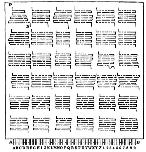
Figure 34 is a representation of the table upon which were arranged the letters of the alphabet, twenty-six in number. Each letter is represented by strips of tin foil, passing from left to right, and right to left, alternately, over a space of an inch square upon a glass table. Such parts of the tin foil are cut out, as will represent a particular letter. Thus, it will be seen that the letter A is represented by those portions of the tin foil which have been taken out, and the remaining portions answer as the conductor. P and N represent the positive and negative ends of the strips, as they pass through the table and reappear, one on each side of the small dot at A. Those two lines which have a dot between, are the ends of the negative and positive wire belonging to one of the letters. Now if a spark from a charged receiver is sent through the wires belonging to letter A, that letter will present a bright and luminous appearance of the form of the letter A. “As the passage of the electric fluid through a perfect conductor is unattended with light, and as the light or spark appears only where imperfect conductors are thrown in its way, hence the appearance of the light at those interrupted points of the tin foil; the glass upon which the conductors are pasted, being an imperfect conductor. The instant the discharge is made through the wire, the spark is seen simultaneously at each of the interruptions, or breaks, of the tin foil, constituting the letter, and the whole letter is rendered visible at once.” This table is placed at one station, and the electrical machine at the other, with 72 wires inclosed in a glass tube connecting the two stations. He could have operated with equal efficiency by using 37 wires having one wire for a common communicating wire, or with 36 wires by substituting the ground for his common wire. It does not appear that it was ever tested to any extent.
Dr. Salva’s Electric Spark Telegraph.
In 1798, Dr. Salva, in Madrid, constructed a similar telegraph, as that suggested by Reizen, (see Voigt’s Magazine, vol. 11, p. 4.) The Prince of Peace witnessed his experiments with much satisfaction, and the Infant Don Antonio engaged with Dr. Salva in improving his instruments. It is stated that his experiments were conducted through many miles. No description of his plans appear to have been given to the public.
Origin of Galvanism.
Galvanism takes its name from Galvani, Professor of Anatomy at Bologna, who discovered it in the year 1790. As the account of the circumstances attending the discovery of this useful and wonderful agent, may not be uninteresting to the reader, we insert it here as related in the “Library of Useful Knowledge.”
“It happened in the year 1790, that his wife, being consumptive, was advised to take, as a nutritive article of diet, some soup made of the flesh of frogs. Several of these animals, recently skinned for that purpose, were lying on a table in the laboratory, close to an electrical machine, with which a pupil of the Professor was amusing himself in trying experiments. While the machine was in action, he chanced to touch the bare nerve of the leg of one of the frogs with the blade of the knife that he held in his hand; when suddenly the whole limb was thrown into violent convulsions. Galvani was not present when this occurred, but received the account from his lady who had witnessed, and had been struck with the singularity of the appearance. He lost no time in repeating the experiment: in examining minutely all the circumstances connected with it, and in determining those on which its success depended. He ascertained that the convulsions took place only at the moment when the spark was drawn from the prime conductor, and the knife was at the same time in contact with the nerve of the frog. He next found that other metallic bodies might be substituted for the knife, and very justly inferred that they owed this property of exciting muscular contractions to their being good conductors of electricity. Far from being satisfied with having arrived at this conclusion, it only served to stimulate him to the farther investigation of this curious subject; and his perseverance was at length rewarded by the discovery, that similar convulsions might be produced in a frog, independently of the electrical machine, by forming a chain of conducting substances between the outside of the muscles of the leg, and the crural nerve. Galvani had previously entertained the idea, that the contractions of the muscles of animals were in some way dependent on electricity; and as these new experiments appeared strongly to favour this hypothesis, he with great ingenuity applied it to explain them. He compared the muscles of a living animal to a Leyden phial, charged by the accumulation of electricity on its surface, while he conceived that the nerve belonging to it, performed the function of the wire communicating with the interior of the phial, which would, of course, be charged negatively. In this state, whenever a communication was made by means of a substance of high conducting power between the surface of the muscle and the nerve, the equilibrium would be instantly restored, and a sudden contraction of the fibres would be the consequence.
“Galvani was thus the first to discover the reason of that peculiar convulsive effect which we now obtain from the Galvanic battery, and he attributed it to a modification of electricity. It was left to another to construct an instrument which would give a constant and increased effect, and develop this extraordinary fluid. Whatever share accident may have had in the original discovery of Galvani, it is certain that the invention of the Pile, an instrument which has most materially contributed to the extension of our knowledge in this branch of physical science, was purely the result of reasoning.
“Professor Volta, of Pavia, in 1800, was led to the discovery of its properties by deep meditation on the developements of electricity at the surface of contact of different metals. We may justly regard this discovery as forming an epoch in the history of galvanism; and since that period, the terms Voltaism, or Voltaic electricity, have been often, in honour of this illustrious philosopher, used to designate that particular form of electrical agency.
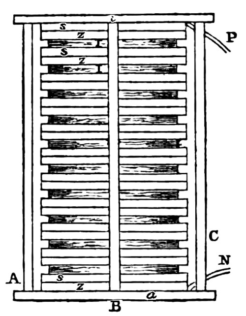
“He had been led by theory to conceive that the effect of a single pair of metallic plates might be increased, indefinitely, by multiplying their number, and disposing them in pairs, with a less perfect conducting substance between each pair. For this purpose he provided an equal number of silver coins, and of pieces of zinc, of the same form and dimensions, and also circular discs of card, soaked in salt water, and of somewhat less diameter than the metallic plates. Of these he formed a pile or column as shown in figure 35, in which three substances, silver, zinc, and wet card, denoted by the letters S, Z, I, were made to succeed one another in the same regular order throughout the series. The efficacy of this combination realized the most sanguine anticipations of the discoverer. If the uppermost disc of metal in the column be touched with the finger of one hand, previously wetted, while a finger of the other hand is applied to the lowermost disc, a distinct shock is felt in the arms, similar to that from a Leyden phial, or still more nearly resembling that from an electrical battery, weakly charged. These discs are supported by two large discs, a and i, of wood, one at the bottom and the other at the top of the pile, with three glass rods, A, B, C, at equal distances around the pile, but not touching it, and are cemented into the wooden base and cover. P represents the wire connecting the silver disc, and N that connecting the zinc.”
Fig. 35.
The Decomposition of Water.
“The chemical agency of galvanism, exerted on fluid conductors, placed in the circuit between the poles of the battery, is very remarkable. Among the simplest of its effects is the resolution of water into its two gaseous elements, oxygen and hydrogen. The discovery of this fact is due to the united researches of Mr. Nicholson and Mr. Carlisle, and was one of the immediate consequences of the invention of the pile by Volta. The most convenient mode of exhibiting the decomposition of water by the Voltaic battery, is to fill, with water, a glass tube; to each end of which, a cork has been fitted so as to confine the water, and to introduce into the tube two metallic wires, by passing one, at each end, through the cork which closes it, allowing the extremities of the wires, that are in the water, to come so near each other as to be separated by an interval of only a quarter of an inch. The wires being then respectively made to communicate with each of the two poles of a Voltaic battery, the following phenomena will ensue. If the wire connected with the positive pole of the battery consists of an oxidable metal, it is rapidly oxidated by the water surrounding it; while, at the same time, a stream of minute bubbles of hydrogen gas arises from the surface of the other wire, which is in connection with the negative pole. But if we employ wires made of a metal which is not susceptible of oxidation by water, such as gold or platina, gas will be extricated from both the wires, and, by means of a proper apparatus may be collected separately.”
We shall now see that these two discoveries, viz. the Voltaic pile, and the decomposition of water by the agency of the former are the bases of a plan for telegraphic purposes.
Samuel Thomas Soemmering’s Description of his Voltaic Electric Telegraph, invented in 1809.
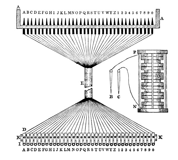
Fig. 36.
“The fact that the decomposition of water may be produced with certainty and instantaneously, not only at short, but at great distances from the Voltaic pile, and that the decomposition may be sustained for a considerable time, suggested to me the idea, that it might be made subservient for the purposes of transmitting intelligence in a manner superior to the plan in common use, and would supersede them. My engagements were such that I have only been able to test the practicability of my plan upon a small scale, and herewith submit, for the Academy’s publication, an account of the experiment.
“My telegraph was constructed and used in the following manner: In the bottom of a glass reservoir, figure 36, of which A A is a sectional view, are 35 golden points, or pins, passing up through the bottom of the glass reservoir, marked A, B, C, &c. 25 of which are marked with the 25 letters of the German alphabet and the ten numerals. The 35 points are each connected with an extended copper wire, soldered to them, and extending through the tube, E, to the distant station; are there soldered to the 35 brass plates, upon the wooden bar, K K. Through the front end of each of the plates, there is a small hole, I, for the reception of two brass pins, B and C; one of which is on the end of the wire connecting the positive pole, and the other the negative pole of the Voltaic column, O. Each of the 35 plates are arranged upon a support of wood, K K, to correspond with the arrangement of the 35 points at the reservoir, and are lettered accordingly. When thus arranged, the two pins from the column are held, one in each hand, and the two plates being selected, the pins are then put into their holes and the communication is established. Gas is evolved at the two distant corresponding points in an instant. For example, K and T. The peg on the hydrogen pole, evolves hydrogen gas, and that on the oxygen pole, oxygen gas.
“In this way every letter and numeral may be indicated at the pleasure of the operator. Should the following rules be observed, it will enable the operator to communicate as much if not more, than can be done by the common telegraph.
“First Rule. As the hydrogen gas evolved is greater in quantity than the oxygen, therefore, those letters which the former gas represents, are more easily distinguished than those of the latter, and must be so noted. For example, in the words ak, ad, em, ie, we indicate the letters A, a, e, i, by the hydrogen; k, d, m, e, on the other hand, by the oxygen poles.
“Second Rule. To telegraph two letters of the same name, we must use a unit, unless they are separated by the syllable. For example, the name anna, may be telegraphed without the unit, as the syllable an, is first indicated and then na. The name nanni, on the contrary, cannot be telegraphed without the use of the unit, because na is first telegraphed, and then comes nn, which cannot be indicated in the same vessel. It would, however, be possible to telegraph even three or more letters at the same time by increasing the number of wires from 25 to 50, which would very much augment the cost of construction and the care of attendance.
“Third Rule. To indicate the conclusion of a word, the unit 1 must be used. Therefore, it is used with the last single letter of a word, being made to follow the ending letter. It must also be prefixed to the letter commencing a word, when that letter follows a word of two letters only. For example: Sie lebt must be represented Si, e1, le, bt, that is the unit 1 must be placed after the first e. Er lebt, on the contrary, must be represented. Er, 1l, eb, t1; that is, the unit 1 is placed before the l. Instead of using the unit, another signal may be introduced, the cross † to indicate the separation of syllables.
“Suppose now the decomposing table is situated in one city, and the pin arrangement in another, connected with each other by 35 continuous wires, extended from city to city. Then the operator, with his Voltaic column and pin arrangement at one station, may communicate intelligence to the observer of the gas at the decomposing table of the other station.
“The metallic plates with which the extended wires are connected have conical shaped holes in their ends; and the pins attached to the two wires of the Voltaic column are likewise of a conical shape, so that when they are put in the holes, there may be a close fit, prevent oxidation and produce a certain connection. It is well known that slight oxidation of the parts in contact will interrupt the communication. The pin arrangement might be so contrived as to use permanent keys, which for the 35 plates or rods would require 70 pins. The first key might be for hydrogen A; the third key for hydrogen B; the fourth key for oxygen B, and so on.
“The preparation and management of the Voltaic column is so well known, that little need be said except that it should be of that durability as to last more than a month. It should not be of very broad surfaces, as I have proved, that six of my usual plates (each one consisting of a Brabant dollar, felt, and a disc of zinc, weighing 52 grains) would evolve more gas, than five plates of the great battery of our Academy.[19] As to the cost of construction, this model which I have had the honour to exhibit to the Royal Academy, cost 30 florins. One line consisting of 35 wires, laid in glass or earthen pipes, each wire insulated with silk, making each wire 22,827 Parisian feet, or a German mile, or a single wire of 788,885 feet in length, might be made for less than 2000 florins, as appears from the cost of my short one.”
Extract from the Journal of the Franklin Institute, vol. 20, page 325.
“To the foregoing notice, we append an article published in Thompson’s Annals of Philosophy, vol. 7, page 162, 1st series, February, 1816. This article is from the pen of Dr. John Redman Coxe, of Philadelphia, and it is believed that the idea of the employment of galvanism, for a telegraph which it suggests, was then original. Those who are acquainted with the history of the progress of electricity, as evolved by the ordinary machine, are aware that experiments had been made with a view to its employment for a similar purpose; but from the inherent difficulties of the subject, the project had been abandoned.
“It is not pretended, that the state of our knowledge on the subject of galvanism, was such at the time the foregoing suggestion was made, as would have enabled any person to apply it practically; this, if done, will be due to the recent discoveries on the subject of electro magnetism; a subject which has been very successfully pursued by the philosophers of our own country, and particularly by Professor Henry, of Princeton. As some of the philosophers of Europe are disputing upon the question of the authorship of proposition for the employment of Galvanic electricity, telegraphically, we have thought that it would not be altogether inopportune, or uninteresting, to publish the article above referred to.
“Use of Galvanism as a Telegraph: in an extract of a Letter from Dr. J. Redman Coxe, Professor of Chemistry, Philadelphia.
“I observe in one of the volumes of your Annals of Philosophy, a proposition to employ galvanism, as a solvent, for the urinary calculus, but which has been very properly, I think, opposed by Mr. Armiger. I merely notice this, as it gives me the opportunity of saying, that a similar idea was maintained in a thesis, three years ago, by a graduate of the University of Pennsylvania. I have, however, contemplated this important agent, as a probable means of establishing telegraphic communications, with as much rapidity, and perhaps less expense, than any hitherto employed. I do not know how far experiment has determined galvanic action, to be communicated by means of wires; but there is no reason to suppose it confined, as to limits, certainly not as to time. Now, by means of apparatus, fixed at certain distances, as telegraphic stations, by tubes, for the decomposition of water, and of metallic salts, &c. regularly ranged, such a key might be adopted as would be requisite to communicate words, sentences, or figures, from one station to another, and so on to the end of the line, I will take another opportunity to enlarge upon this, as I think it might serve many useful purposes; but like all others, it requires time to mature. As it takes up little room, and may be fixed in private, it might, in many cases, of besieged towns, &c. convey useful intelligence, with scarcely a chance of detection by the enemy. However fanciful in speculation, I have no doubt that sooner or later, it will be rendered useful in practice.”
“I have thus, my dear sir, ventured to encroach upon your time, with some crude ideas, that may serve to elicit some useful experiments in the hands of others. When we consider what wonderful results have arisen from the first trifling experiments of the junction of a small piece of silver and zinc in so short a period, what may not be expected from the further extension of galvanic electricity: I have no doubt of its being the chiefest agent, in the hands of nature, of the mighty changes that occur around us. If the metals are compound bodies, which I doubt not, will not this active principle combine those constituent in numerous places, so as to explain their metallic formation? and if such constituents are in themselves aeriform, may not galvanism reasonably tend to explain the existence of metals in situations to which their specific gravities certainly do not entitle us to look for them?”
Ronald’s Electric Telegraph, invented in 1816.
From the Encyclopedia Britannica, 7th edition, page 662.
“M. Cavællo suggested the idea of conveying intelligence by passing a given number of sparks through an insulated wire in given spaces of time; and some German and American authors have proposed to construct galvanic telegraphs by the decomposition of water. Mr. Ronalds, who has devoted much time to the consideration of this form of the telegraph, proposes to employ common electricity to convey intelligence along insulated and buried wires, and he proved the practicability of such a scheme, by insulating eight miles of wire on his lawn at Hammersmith. In this case the wire was insulated in the air by silk strings. But he also made the trial with 525 feet of buried wire; with this view he dug a trench four feet deep, in which he laid a trough of wood two inches square, well lined within and without with pitch; and within this trough were placed thick glass tubes, through which the wire ran. The junction of the glass tubes was surrounded with shorter and wider tubes of glass, the ends of which were sealed up with soft wax.
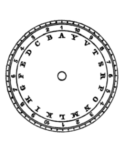
“Mr. Ronalds now fixed a circular brass plate, figure 37, upon the second arbour of a clock which beat dead seconds. This plate was divided into twenty equal parts, each division being worked by a figure, a letter, and a preparatory sign. The figures were divided into two series of the units, and the letters were arranged alphabetically, omitting J, Q, U, W, X and Z. In front of this was fixed another brass plate as shown in figure 38, which could be occasionally turned round by the hand, and which had an aperture like that shown in the figure at V, which would just exhibit one of the figures, letters and preparatory signs, for example, 9, v, and ready. In front of this plate was suspended a pith ball electrometer, B, C, figure 38, from a wire D, which was insulated, and which communicated on one side with a glass cylinder machine, and on the other side with the buried wire. At the further end of the buried wire, was an apparatus exactly the same as the one now described, and the clocks were adjusted to as perfect synchronism as possible.
Fig. 37. Fig. 38.
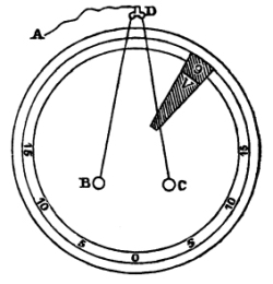
“Hence it is manifest, that when the wire was charged by the machine at either end, the electrometers at both ends diverged, and when it was discharged, they collapsed, at the same instant. Consequently, if it was discharged at the moment when a given letter, figure, and sign on the lower plate, figure 37, appeared through the aperture, figure 38, the same figure, letter and sign would appear also at the other clock; so that by means of such discharges at one station, and by marking down the letters, figures and signs, seen at the other, any required words could be spelt.
“An electrical pistol was connected with the apparatus, by which a spark might pass through it when the sign prepare was made, in order that the explosion might excite the attention of the superintendent, and obviate the necessity of close watching.
“Preparatory signs. A, prepare; V, ready; S, repeat sentence; P, repeat word; N, finish; L, annul sentence; I, annul word; G, note figures; E, note letters; C, dictionary.”
Electro Magnetism.
We have now to notice a discovery, which forms the basis of those modern telegraphs in which the principle of electro magnetism is adopted. The following is an extract from the “Library of Useful Knowledge,” in relation to the discovery:
“The real discoverer of the magnetic properties of electric currents M. Oersted, Professor of Natural Philosophy, and Secretary of the Royal Society of Copenhagen. In a work which he published in the German, about the year 1813, on the identity of chemical and electrical forces, he had thrown out conjectures concerning the relations subsisting between the electric, galvanic and magnetic fluids, which he conceived might differ from one another only in their respective degrees of tension. If galvanism, he argued, be merely a more latent form of electricity, so magnetism may possibly be nothing more than electricity in a still more latent form; and he, therefore, proposed it as a subject worthy of inquiry, whether electricity employed in this, its most latent form, might not be found to have a sensible effect upon a magnet. It is difficult clearly to understand what he meant by the expression of latent states, as applied to electricity, but it may be sufficient for us to know, that in the various endeavours he subsequently made to verify his conjectures, he was led to such forms of experiment as afforded decisive indications of the influence of Voltaic currents on the magnetized needle. Yet, even after he had succeeded thus far, it was a matter of extreme difficulty to determine the real direction of this action, and it was not till the close of the year 1819, that his perseverance was at length rewarded by complete success.
“The first account of his discovery that appeared in England is contained in a paper, which he himself communicated, in Thompson’s Annals of Philosophy, for October, 1820, vol. 16, page 273; and in which the following experiments are described. The two poles of a powerful Voltaic battery were connected by a metallic wire, so as to complete the galvanic circuit. The wire which performs this office he called the uniting wire; and the effect, whatever it may be, which takes place in this conductor, and in the space surrounding it, during the passage of the electricity, he designates by the term electric conflict, from an idea that there takes place some continued collision and neutralization of the two species of electric fluids, while circulating in opposite currents in the apparatus. Then taking a magnetic needle, properly balanced on its pivot, as in the mariner’s compass, and allowing it to assume its natural position in the magnetic meridian, he placed a straight portion of the uniting wire horizontally above the needle, and in a direction parallel to it; and then completed the circuit, so that the electric current passed through the wire. The moment this was done, the needle changed its position, its ends deviating from the north and south towards the east and west, according to the direction in which the electric current flowed, so that by reversing the direction of the current the motion of the needle was also reversed. The general law he expressed as follows: ‘That end of the needle which is situated next to the negative side of the battery, or towards which the current of positive electricity is following, immediately moves to the westward.’
“The deviation of the needle is the same, whether the uniting wire, instead of being immediately above the needle, be placed somewhat to the east or west of it, provided it continue parallel to and also above it. This shows that the effect is not the result of a simple attractive or repulsive influence, for the same pole of the magnetic needle which approaches the uniting wire, when placed on its east side, recedes from it when placed on its west side.”
[20] “Soon after this important discovery of Oersted’s was made, M. Ampère established the second fundamental law of electro magnetism, that the two conducting wires from the poles of the battery, when conveniently suspended, attracts each other when they transmit electrical currents moving in the same direction, and repel each other when the currents which they transmit have opposite directions.
“On the 25th Sept. 1820, M. Arago communicated to the French Institute the important discovery that the electrical current possesses, in a very high degree the power of developing magnetism in iron or steel. Sir H. Davy communicated a similar fact to Dr. Wollaston on the 12th of November, 1820, and Dr. Seebeck laid before the Royal Academy of Berlin a series of experiments on the same subject.
“M. Arago found that the uniting wires of a powerful Voltaic battery attracts iron filings often with such force as to form a coating around the wire ten or twelve times thicker than itself. This attraction, as he found, did not originate in any magnetism previously possessed by the iron filing, which he ascertained would not adhere to iron, and that it was not a case of common electrical attraction, was evident from the fact that copper and brass filings were not attracted by the uniting wire. M. Arago likewise found, that the iron filings began to rise before they came in contact with the uniting wire; and hence he drew the conclusion, that the electric currents converted each small piece of iron into a temporary magnet. In following out this view, the French philosopher converted large pieces of iron into temporary magnets and also small steel needles into permanent ones, (by employing the helix.) Sir H. Davy and Dr. Seebeck obtained analogous results without knowing what had been previously done in France.
“A galvanometer was first constructed by Professor Schweigger, of Halle, very soon after the first discovery of electro magnetism, and by him called an electro magnetic multiplier.”
In the year 1820, Ampère predicted the possibility of making the deflection of the magnetic needle, by the agency of the galvanic fluid, serve the purposes of transmitting intelligence. In page 19 of his memoir, he thus resolves the problem:
“As many magnetic needles as there are letters of the alphabet,” he says, “which may be put in action by conductors; which may be made to communicate successively with the battery by means of keys; which may be pressed down at pleasure, might give place to a telegraphic correspondence which would surmount all distance and would be as prompt as writing speech to transmit thought.”
“The next step in the progress of discovery, was that of making magnets of extraordinary power by means of a galvanic battery. This seems to have been first accomplished by Prof. Moll, of Utrecht, and Professor Henry, of Princeton, who was able to lift thousands of pounds weight by his apparatus.”
The following Extract is taken from a Work on Electro Magnetism published by Jacob Green, M. D. Professor of Chemistry in Jefferson Medical College, 1827.
“In the very early stage of electro magnetic experiments, it had been suggested, that an instantaneous telegraph might be constructed by means of conjunctive wires, and magnetic needles. The details of this contrivance are so obvious, and the principles on which it is founded so well understood, that there was only one question which could render the result doubtful. This was, whether by lengthening the conjunctive wires, there would be any diminution in the electrical effect upon the needle. It is the general opinion, that the electrical fluid, from a common electrical battery, may be transmitted, without any sensible diminution, instantaneously, through a wire three or four miles in length. At the philosophical dinner, as it has been called, got up a number of years ago by some gentlemen of Philadelphia, on the banks of the Schuylkill, it may be recollected that Dr. Franklin killed a turkey with the electric shock, transmitted across the river, a distance of more than half a mile; and Dr. Watson, who was also at the pains of making some experiments of this kind, asserts that the electric shock was transmitted, instantaneously, through the length of 12,276 feet. Had it been found true that the galvanic fluid could be transmitted in a moment through a great extent of conducting wire, without diminishing its magnetic effect then no question could have been entertained as to the practicability and importance of the suggestion adverted to above, with regard to the telegraph. Mr. Barlow, of the Royal Military Academy, who has made a number of successful experiments and investigations in electro magnetism, fully ascertained that there was so sensible a diminution with only 200 feet of wire, as to convince him at once of the impracticability of the scheme.
Triboaillet’s Proposition.
[21] “In 1828, M. Victor Triboaillet de Saint Amand proposed to establish a correspondence from Paris to Brussels, by placing along the highway, and at some feet deep, a metallic wire, about a line or a line and a half diameter. He recommended to cover the wire with shellac, upon which was to be wound silk, very dry, which should be covered in their turn with a coating of resin. The whole was then to be put into glass tubes carefully luted up with a resinous substance and secured by a last envelope in the earth, then varnished over and hermetically sealed. Then, by means of a powerful battery, he would communicate the electricity to the conducting wire, which would transmit the current to the opposite point to an electroscope, destined to render sensible the slightest influence, and left to each one to adopt at pleasure the number of motions to express the words or letters which they might need.”
Fechner’s Suggestion.[22]
“Fechner, in his manual of galvanism, (Voss, 1829, page 269,) remarked, that the electro magnetic effects of the galvanic current would be far more appropriate for the giving of signs than Soemmering’s plan by the decomposition of water.”
He suggested that wires, having twenty-four multiplicators should be extended between Leipsic and Dresden, and there connected, alternately, with a galvanic column, for telegraphic purposes. Indeed, he ventured to prophecy, that probably hereafter such a connection between the central point of a kingdom, and different provinces might be arranged as there was existing in animal bodies, between the central point of organic structure of particular members and nerves.
Magneto Electricity.
We come now to give an account of a new branch in the science of electricity, viz. magneto electricity; which Dr. Faraday was the first to discover in the year 1831. As this species of electricity has been applied to several of the plans of electric telegraphs, which we shall describe, it is desirable that some account should be given of its discovery, and of the instrument by which it is generated.
The following is an extract from “Daniell’s Introduction to Chemical Philosophy” 2d edition, London, 1843.
“The phenomena of electro magnetism are produced by electricity in motion; accumulated electricity, when not in motion, exerts no magnetic effects. Dr. Faraday early felt convinced that “as every electric current is accompanied by a corresponding intensity of magnetic action at right angles to the current, good conductors of electricity, when placed within the sphere of this action, should have a current induced through them, or some sensible effect produced, equivalent in force to such a current.” These considerations, with their consequence, the hope of obtaining electricity from ordinary magnetism, stimulated him to investigate the subject experimentally, and he was rewarded by an affirmative answer to the question proposed. He thus became, like Oersted, the founder of an entirely new branch of natural philosophy.
“If a wire connecting the two ends of a delicate galvanometer be placed parallel and close to the wire connecting the poles of a Voltaic battery, no effect will be produced upon the needle, however powerful the current may be. If the points opposed in the two wires be multiplied by coiling the one, as a helix, within the convolutions of the other, coiled in the same way, both being covered with silk to prevent metallic contact, still no effect will be discernible so long as the current is uninterrupted. When, however, the current of the battery is stopped by breaking the circuit, the needle is momentarily deflected, as by a wave of electricity passing in the same direction as that of the main current. Upon allowing the needle to come to a state of rest, and then renewing the contact, a similar impulse will be given to it in the contrary direction. While the current continues, the needle returns to its state of rest, again to be deflected in the first direction by stopping the current. Motion may be accumulated to a considerable amount in the needle, by making and breaking the contacts with the battery in correspondence with its swing. The same effects are produced when, the current being uninterrupted, the conducting wire is made suddenly to approach or recede from the wire of the galvanometer. As the wires approximate, there will be a momentary current induced in the direction contrary to the inducing current; and as the wires recede, an induced current in the same direction as the inducing current.
“As this Volta electric induction is obviously produced by the transverse action of the Voltaic current, in one case, by the mechanical motion of the wire, and in the other at the moments of generation and annihilation of the current, Dr. Faraday thought that the sudden induction and cessation of the same magnetic force in soft iron, either by the agency of a Voltaic current, or by that of a common magnet, ought to produce the same results. He constructed a combination of helices (8) upon a hollow cylinder of pasteboard: they consisted of lengths of copper wire, containing, altogether, 220 feet; four of these were connected end to end, and then with the galvanometer. The other intervening four were also connected end to end, and then with the Voltaic battery. In this form a slight effect was produced upon the needle by making and breaking contact. But when a soft iron cylinder, seven-eighths of an inch thick and twelve inches long, was introduced into the pasteboard tube, surrounded by the helices, the induced current affected the galvanometer powerfully. When the iron cylinder was replaced by an equal cylinder of copper, no effect beyond that of the helices alone was produced.
“Similar effects were then produced by ordinary magnets. The hollow helix had all its elementary helices connected with the galvanometer, and the soft iron cylinder having been introduced into its axis, a couple of bar magnets were arranged with their opposite poles in contact, so as to resemble a horse-shoe magnet, and contact was then made between the other poles and the ends of the iron cylinder, by which it was converted, for the time, into a magnet; by breaking the magnetic contacts, or reversing them, the magnetism of the iron cylinder could be destroyed or reversed at pleasure. Upon making magnetic contact, the needle was deflected; continuing the contact, the needle became indifferent, and resumed its first position; on breaking contact, it was again deflected, but in the opposite direction to the first effect, and then it again became indifferent. When the magnetic contacts were reversed, the deflections were reversed. The actual contacts of the magnets with the soft iron is not essential to the success of these experiments, for their near approximation induces sufficient magnetism in the cylinder to generate the electric current, which affects the needle. The first rise of the magnetic force induces the electric wave in one direction; its sudden decline, in the opposite. Mechanical motion of a permanent magnetic pole in one direction, across the coils of the helix, will produce the same effect as the sudden induction of the magnetism in the soft iron, and its motion in the opposite direction will cause a corresponding effect with its annihilation, when the soft iron cylinder is removed from the helix, and one end of a cylindrical magnet thrust into it, the needle is deflected in the same way as if the magnet had been formed, by either of the two preceding processes. Being left in, the needle will resume its first position, and then being withdrawn, the needle will be deflected in the opposite direction. On substituting a small hollow helix, formed round a glass tube, for the galvanometer, in these experiments, and introducing a steel needle, it will be converted into a magnet, provided care be taken not to expose it to the opposite action of the reverse current; and if the continuity of the conducting wire be broken, at the moment when the secondary electric wave is passing through it, a bright spark may be obtained.
“The connection of electro magnetical and magneto electrical phenomena may be exhibited in a very striking way, by employing any of the apparatus, by which the rotary motions of the magnet or conducting wire, are produced by a current of electricity, to generate electric currents by the mechanical rotations of the magnet or wire. For this purpose, the galvanometer may be substituted for the battery, and when the wire is made to turn round the pole of the magnet, or the pole of the magnet round the wire, in one direction, the needle will be deflected to one side; and to the other by the opposite rotation. Nothing can be better shown that magneto electric is the converse of electro magnetic action.
“Dr. Faraday by rotating a copper disc between the poles of a horse-shoe magnet, produced a constant current of electricity in one direction, and deflected the needle of the galvanometer; one wire being connected with the disc, and the other with the arbour. By turning the disc in one direction, the circuit will pass from the axis to the circumference; by turning it in the opposite direction, the current will flow from the circumference to the axis.”
Fig. 39.
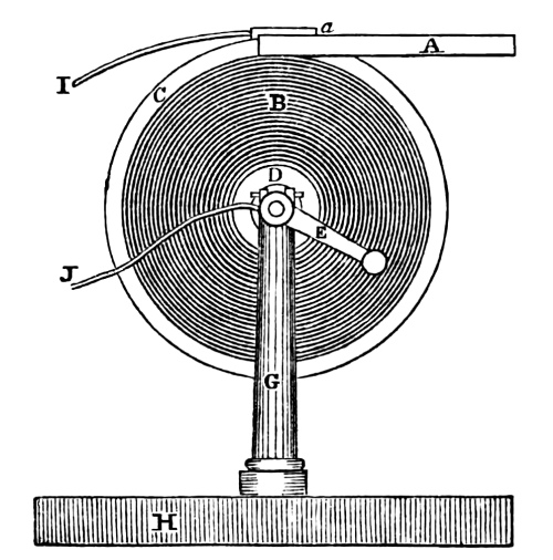
Figure 39 represents a side view of the instrument. B shows the copper disc permanently secured upon its axis, and which is turned by means of the crank, E. G represents one of the standards which support the axis. H is the platform upon which the various parts are arranged. The edge, C, of the copper disc, is amalgamated so as to make a perfect connection with the amalgamated segment, a, to which is soldered a wire, I, leading to the galvanometer. That portion of the disc, B, which is shaded, is not amalgamated. J is the other wire proceeding from the galvanometer, and both it and the axis are amalgamated, at the points of connection. A is the permanent magnet, with its poles on each side of the copper disc, B, opposite the amalgamated portion of the rim.
Fig. 40.
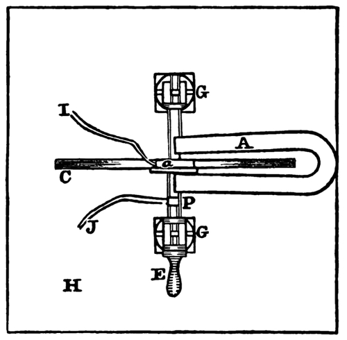
Figure 40, represents a top view of the instrument, H is the platform; C the disc; a the segment; A the permanent magnet; J the wire attached to the axis, P; G and G are the two standards. E the crank; and I the wire attached to the segment a.
Mr. Saxton,[23] in a letter to Mr. Lukens, dated, London, April 14th, 1832, after describing Dr. Faraday’s rotating disc, figures 39 and 40, says, “I have made this experiment in a different way, and succeeded satisfactorily. The method was as follows: A coil of wire wrapped with silk, similar to that used in the galvanometer, was attached, by the ends, to the wires of the galvanometer. On passing this roll, backward and forward, upon one of the poles of a horse-shoe (permanent) magnet, or placing it upon and removing it from either pole, I have made the needle of the galvanometer to spin round rapidly.” Figure 41, represents Mr. Saxton’s plan.
Fig. 41.
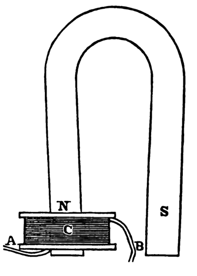
N and S represent the north and south poles of the horse-shoe permanent magnet. C is the coil of wire, wound round a spool of an oblong shape, through the centre of which there is an opening sufficiently large to admit either of the prongs of the magnet through it. A and B are the ends of the wire leaving the coil, and are connected with the galvanometer.
Mr. Saxton on the 2d of May, 1832, obtained the spark by the following arrangement of the permanent magnet and the helix of wire round the armature. In relation to this instrument, he thus writes to Mr. Lukens, of Philadelphia, dated, London, May 11th, 1832. Jour. Frank. Int. vol. 13, p. 67. “Since my last I have heard of a method of producing a spark from a magnet, discovered I think by an Italian.[24] This experiment I made at once upon a large horse-shoe magnet, which I am making for Mr. Perkins and his partners. One of your large magnets will answer the same purpose. Make a cylinder of soft iron of an inch, or three-fourths of an inch, in diameter, and of the usual length of the keeper; place two discs of brass or wood upon this cylinder, and at such a distance apart that they will conveniently pass between the poles of the magnet; between these wind, say fifty feet of bobbin wire, which may be of iron covered with cotton; let the ends of this coil be bent over the ends of the cylinder and brought down until they touch the poles of the magnet. The ends should be of such a length, that on bringing the cylinder to the magnet, one of the ends will touch, when the cylinder is about half an inch from the magnet, and the other at one-fourth of an inch. The cylinder being thus arranged, and in contact with the magnet, on drawing it suddenly away a spark will pass between the end of the wire, and the pole of the magnet.”
Fig. 42.
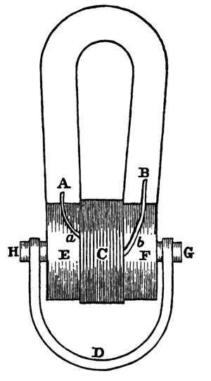
Figure 42 represents the instrument as first constructed by Mr. Saxton, in London.[25] A and B are the ends of the helix, surrounding the cylindrical bar of soft iron between E and F, filling the cavity which has been formed out of the solid iron. The size of bar between the collars E and F, thus formed, is the same as the projections H and G. The wire, a, proceeds from the outside of the coil and makes a suitable contact upon the prong, A, of the magnet: b proceeds from the bottom of the coil, where the winding commenced and makes a similar contact upon the prong, B, of the permanent magnet. One wire extends a little further upon the magnet than the other, so that the shorter one may break its connection sooner than the longer. H and G are projections from the sides of the armature, to which the handle, D, is secured. Let the armature, with its helix, be held up against the ends of the prongs of the permanent magnet; and the wires a and b, in perfect contact with their respective prongs, as shown in the figure; if, while in this condition, the keeper is suddenly withdrawn, a spark will appear at the end of the short wire, as it breaks its contact with the prong of the magnet.
Mr. Saxton, however, was still further successful, the following year, in carrying out an idea which occurred to him on the 6th of December, 1832, of producing the same phenomena, with a more convenient and powerful rotating instrument.[26] This new arrangement he was able to test on the 20th of June, 1833, and obtained the spark. On the 22d, he made an unsuccessful attempt, in the presence of Prof. Rogers, of Philadelphia, at the decomposition of water. On the 30th of June he exhibited it at a meeting of the British Association at Cambridge, before Dr. Faraday, Dr. Brewster, Prof. Forbes, Dr. Dalton, and many other distinguished and scientific gentlemen. The experiments made by it were the exhibition of the spark, giving shocks, &c. On the third of July, Mr. Saxton succeeded in decomposing water, by adding a little sulphuric acid, and on the 25th of August, he ignited and melted platinum wire.
Fig. 43.
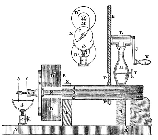
Figure 43 exhibits a side view of the instrument: a, a, a, is a compound permanent magnet, consisting of three steel plates, put together, side by side. B and C are two wooden supports, upon the platform A A. To these supports the magnet is permanently secured, by a yoke, S, through which pass two screws into the wooden supports below. M is a cross bar, into which, and at right angles with it, are screwed two arms of round soft iron, R, about five-eighths of an inch in diameter, the whole forming the armature or keeper of the magnet. Upon these two projecting arms, are placed two coils, D′ and D, of copper wire, insulated with silk. The whole is very securely fastened upon the steel spindle, N, which has its journals in the supports, B and B′. On the end of the spindle, N, near the curve of the magnet, there is a small band pulley, F, which is driven by the band or cord of the large wheel, E, and the crank, J. The axis of the large wheel passes through a long socket, L, in the top of the column, H; on one end of the axis the band wheel is fastened and on the other the crank. By this arrangement a very rapid and quiet rotary motion is given to the armature.
In the column, H, there is a socket, into which the stem of the upper part of the column, G, is fitted, which admits of the large wheel being raised or lowered, so as to prevent the band from slipping, and when properly adjusted it is secured by the screw, I. O is an ivory hub, sliding over that part of the spindle immediately projecting beyond the cross bar, M. Upon this ivory hub is a copper disc, C, with a socket, n: b, is a needle made of platinum, which, with its socket, m, is nicely fitted upon the end of the steel spindle, so as to be adjusted to any required angle with the armature, and when adjusted to retain its position. The two ends of the two coils, which leave the centre of the helices, are made to form a contact with the soft iron arms, R R, passing through the coils, D′ and D, thus making the circuit complete with the needle b, upon the end of the spindle, N, by a continuous metallic connection of the arms, with the cross bar, M, and through the cross bar to the spindle, N, in contact with the needle, b. The two ends of the two coils, leaving the outside of the helices, are joined in one, and as they pass through the cross bar, M, are insulated from it, by a piece of ivory, inserted in the cross bar. The united wire then passes into and through the ivory hub, e, forming a perfect contact with the copper disc, c, underneath its socket, n: d, is a cup of mercury, in which the copper disc, c, is always immersed, and the needle, b, twice in every revolution of the armature. The cup, d, is so constructed as to rise and fall, by means of a stem, i, sliding vertically into a socket, e, of its support, and is secured to its position by the screw, h. In this way, its proper height for breaking and closing the circuit may be easily obtained, when the armature is rotating. The proper position for the needle, b, is that in which it is just leaving the mercury, as the keeper arrives at the position, in which its magnetism is neutralized. This position is seen at X, where D″ and D′ are the sides of the coils; c the copper disc; m the cross bar of the armature; R the arm passing through the coil; and b the needle, at that angle which it requires, when the armature is vertical or at its neutral position. It will be observed that the needle is just leaving the mercury, d.
Fig. 44.
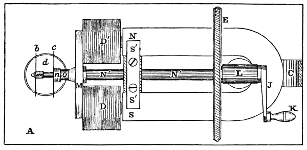
Figure 44 represents a top view. N and S represent the north and south poles of the permanent magnet. N′ and N′ is the spindle, parallel with the prongs of the magnet, and equidistant from them; L is the socket of the band wheel; D′ and D the horizontal position of the coils; M is the cross bar; b the needle; c the copper disc, and m and n their respective sockets; o the ivory hub; d the cup of mercury; A the platform; and S′ and S′ the yoke through which pass two screws to secure the magnet to the wooden support below.
When the armature is made to rotate, it becomes a temporary magnet, by the laws of magnetic induction, whenever the arms carrying the helices come opposite to the poles of the permanent magnet, and when these soft iron arms have reached the point at right angles to the magnet, or vertical, their magnetism for an instant is destroyed, and are as instantaneously reversed from what they were before reaching that point. They are also magnetic, just in that proportion as they recede from or approach to the poles of the permanent magnet.
Hence, first, one arm is the south pole, when opposed to the north pole of the magnet; and the other arm a north pole, when opposed to the south pole of the magnet. But when they have made a half revolution on their axis, from their first position, their magnetism is reversed. The arm which was a south pole, has become a north pole; and the arm that was a north pole has become a south pole. Thus, by the rotation of the armature, direction of the induced current in the arms, become changed, as often as they are alternately brought opposite the poles of the permanent magnet, which is twice in every revolution of the armature.
It follows, then, by the laws of magneto induction, that as often as the arms become magnetic, they induce corresponding opposite electric currents in the wire surrounding those arms, provided the circuit of the coils is complete. The disc, which is in metallic connection with two ends of the wire leaving the coils, (one from each coil,) is always immersed in the mercury of the cup. The needle, however, which is in connection with the other two wires from the two coils, (one from each coil,) is not always immersed, but only when the armature is at a certain position in relation to the permanent magnet. The circuit then can only be closed when the needle is immersed, as well as the disc. Upon inspecting the figure, it will be found that the needle is immersed at the time the arms are passing the poles of the magnet, and that when they arrive at the vertical or neutral position, the needle has just broken its connection with the mercury, and at that instant the spark is observed.
Professor Daniell observes, that “by means of this magneto electrical machine, all the well known effects of Voltaic currents may be very commodiously produced. When the communication is made between the spindle and the revolving disc, by means of a fine platinum wire, instead of the dipping points, the wire may be maintained at a red heat; although the effect being produced by alternating currents in opposite directions, a kind of pulsation, or intermission of the light, may be discerned. Upon making the communication between the two mercury cups, by means of copper cylinders grasped in the hands, a continued painful contraction of the muscles of the arm takes place, which destroys voluntary motion, and, under certain circumstances, is perfectly intolerable.
“The general expression of these phenomena may be thus stated: whenever a piece of metal is passed, either before a single pole, or between the opposite poles of a magnet, or before electro magnetic poles, whether ferruginous or not, so as to cut the magnetic curves, (or lines, which would be marked out by a spontaneous arrangement of iron filings,) electrical currents are produced across the metal, transverse to the direction of motion.”
Dr. Page’s Magneto Electric Machine.
This important instrument also depends, for its action, upon the principle discovered by Dr. Faraday, that electricity was developed in conducting bodies, when they were moved in a certain direction, in the neighbourhood of permanent magnets. Since the beautiful and ingenious invention which Mr. Saxton was the first to make, no valuable improvements have been made in this machine, except those introduced by Professor Page.
The first important change in the machine, was the adaptation of his pole changer to the machine, in place of the break pieces, which were used in all the modifications up to that time; and another equally useful improvement, consisted in the arrangement of the permanent magnets and armatures. Previous to this last improvement, these machines were constructed with a single permanent magnet, and one or more revolving armatures, necessarily involving great disadvantages. Page’s improvements were completed in February, 1838, and shortly after published in Silliman’s Journal. He was also the first to suggest the combination of several machines under one mechanical movement, as the best mode of augmenting power in this way.
The combined machine, described in Daniell’s Introduction to Chemical Philosophy, as invented by Wheatstone, about two years since, is the same as that described, and represented by Dr. Page in Silliman’s Journal in 1838. In the same publication, Dr. Page described the arrangement of the permanent magnets and armatures, as shown in the annexed figures. The adaptation of the pole changer, which, in connection with this machine, is called the Unitrep, Dr. Page has given to the public. But as he has never allowed the improvement, which consists in the use of two or more permanent magnets and straight armatures, to be sold with his knowledge and consent, he intends to claim a patent for the same; it having been decided by our courts, that the publication of an invention by the inventor, does not affect his right to a patent, provided he does not allow the invention to be sold and used.
The figures 45, 46 and 47, exhibit one of Page’s machines with his early improvements.
Figure 45, is a side elevation of the machine.
Figure 46, is a top view.
Figure 47, are views of the revolving armatures and coils.
In Figure 45, representing a side view of the machine, B and B are the compound permanent steel magnets, composed of six bars each of the U form, mounted upon the brass pillars, P, P, P, P, which are fastened into the common platform of the whole machine. Through the platform there pass stout rods, R and R, and upwards through two brass straps, above the magnets, B and B. These straps or yokes secure the magnets from any motion by means of the screw nuts. A is a circular case of pasteboard, containing the armatures and coils. H is a band wheel surrounding the case, for mechanical connection with any source of power that may be used to keep the machine in motion. I′ and I are two metallic studs, with an aperture passing vertically from the top, to the depth of an inch, for the reception of connecting wires, and then, by means of a screw at its side, to make a perfect contact. There are two other studs directly behind them. G and J are the two pulley wheels, with their band and crank, by which a rapid rotary motion is given to the armatures and coils. These pulleys are supported by the standard. From the bottom of the studs I′ and I, as also from those directly behind them, proceed wires which are carried along below the platform, and pass up through it between the pilliar, P, and the revolving armatures, to the shaft; there being one on each side of the axis.
Fig. 45.
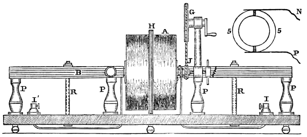
Fig. 46.
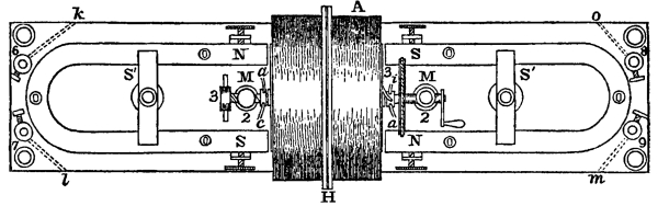
Figure 46, represents a top view of the instrument. A is the case containing the armatures and coils, and H the band wheel. N, S and N, S, are the north and south poles of the permanent magnets. S′ and S′ are the yokes by which the magnets are secured to the platform, and the screws near the poles of the magnets are for the purpose of setting the magnets to any required position, laterally, and securing them in it. M and M are the tops of the two pilliars, which support the shaft of the armatures and coils. The bearings are so made as to allow the apparatus to revolve with as little friction as possible: 3 and 3 represent the set screws against the ends of the shaft, for adjusting the ends of the permanent magnets; by which means, the armatures may be allowed to pass very near the ends of the magnets without touching. 6, 7, 8, and 9 are the receiving studs, by which the wires from any other instrument may be connected with the machine. The wire, a, in contact with the unitrep, as before stated, is continued and soldered to the receiving stud, 6; in the same manner, c, also in contact with the unitrep, is connected with 7; and also 3 with 8; and a with 9. The manner in which these wires, a, c, 3, and a, form their contact with the shaft, is seen at N and P, figure 45, of which 5 and 5 represent a section of the shaft and unitrep.
Fig. 47.
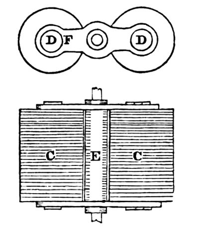
Figure 47 represents the revolving armatures and coils, with the case taken off. C and C are the two coils of insulated copper wire, surrounding two straight bars of soft iron, represented in the end view by D and D. E is the shaft. The two armatures and coils are secured to the two brass straps F, which are themselves fastened upon the shaft. The armatures are allowed to project through the straps about the sixteenth of an inch.
On each end of the shaft is attached an unitrep, consisting of two cylindrical segments of silver, as seen at 5 and 5, figure 45; insulated from each other, and secured to a cylinder of ivory or wood, upon the shaft, so as to revolve with it. The terminations of the coils of wire upon the armatures, are soldered to the segments of silver, and as the unitrep turns, it brings opposite ends of the wires, alternately, upon the stationary wires or conductors, P and N: (in figure 46 they are represented by a and c, and 3 and a.) The opposing currents of the coils, in each half revolution, are, by this contrivance, made to form one continuous current. Hence, the name unitrep (to turn together.) There being two unitreps, and corresponding conducting wires, and screw cups, the induced currents from the two coils may be combined in several ways, after the manner of combining separate batteries.
Let the wires below the base board be all properly connected with the receiving cups, as heretofore described. Then let the wire from 6, (represented by dots,) to k, be connected with the wire 9 and m; and also the wire 7 and l, with the wire 8 and 0. Let one of the united wires be connected with one wire leaving the coil of an electro magnet; and the other united wire be joined to the other wire of the electro magnet of the telegraph, or any other instrument designed to operate by a galvanic battery. When this preparation is finished, if the armatures and coils are made to revolve rapidly, a powerful current is formed in the induced coils, C and C, figure 47, capable of performing all the experiments generally made by means of the galvanic battery.
Dr. Page has made a very important discovery in connection with this machine, not now to be made known; but, suffice it to say, the single machine which he has now in his possession, on Christmas day, 1844, operated Morse’s telegraph, through the circuit of 80 miles; half this circuit being wire, the other half the earth. This machine makes an electro magnet sustain 1000 pounds, and melts a platinum wire one-fortieth of an inch in diameter.
The Pole Changer.
We introduce here a description of an instrument used for reversing the direction of the galvanic current, and which is applied in the operation of several kinds of electric telegraphs. There is a variety of modes by which the same object is attained, but as this appears the most simple, we have chosen it in preference to others.
The following figures, 48, 49 and 50, are three views of the instrument as it appears when looking down upon it, in its three changes. First, that in which the current is broken and the needle vertical. Second, in which the circuit is closed and the needle deflected to the right. Third, in which the circuit is closed and the needle deflected to the left. Each figure has, in connection with the pole changer, the battery, or any other generator of the electric fluid, represented by N and P, and the galvanometer represented by G. In each of the figures, the circles numbered 1, 2, 3, 4, 5, 6, 7, and 8, represent cups, filled with mercury, let into the wood of the platform, and made permanent. The small parallel lines terminating in these cups, represent copper wires or conductors.
Fig. 48.
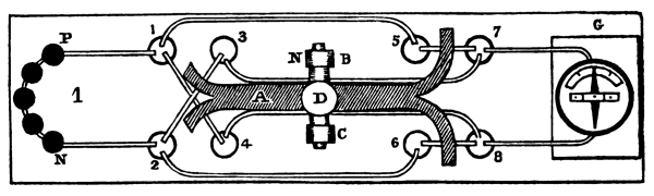
A, figure 48, represents a horizontal lever of wood, or some insulating substance, with its axis supported by two standards, B and C, by which it can easily vibrate. D represents an ivory ball, mounted upon a rod, inserted in the lever, and extending a few inches above it. It serves as a handle, by which to direct the elevation or depression of either end of the lever. Both ends of the lever branch out, presenting two arms each. Through each arm passes a copper wire, insulated from each other. The left hand branches support the wires which connect the mercury cups, 1 and 4, and 2 and 3, together. The right hand branches support the wires which connect the cups 5 and 7, and 6 and 8, together. The ends of these wires directly over the mercury cups are bent down, so that they may freely enter their respective vessels when required. The other wires are permanently secured to the platform. The position of the lever is now horizontal, and the bent ends of the wires, which it carries, are so adjusted, that none of them touch the mercury, consequently, there is no connection formed between the battery and galvanometer, and the needle is vertical. The ivory ball, it will be observed, is directly over the centre of the axis, and in that position required to break the circuit. Thus, the wires, 2 and 3, 1 and 4, 5 and 7, 6 and 8, are each out of the mercury, and the circuit being broken the fluid cannot pass.
Fig. 49.
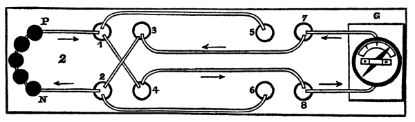
Figure 49 represents those connections which are formed when the left hand side of the lever is depressed, immersing in the mercury those wires supported by it. The ball and lever are omitted for the better inspection of the wires. Now the circuit is closed, and the current is passing from P, of the battery, to the mercury cup, 1; then along the cross wire to 4; to 8; to the coils of the multiplier, deflecting the needle to the right; then to 7; to 3; then along the cross wire, (which is not in contact with wire 1 and 4,) to 2; to the N pole of the battery. The arrows also show the direction of the current. It will be observed that the cups 5 and 7, and 6 and 8 are not now in connection, and consequently the current cannot pass along the wires 1 and 5, and 2 and 6.
Fig. 50.
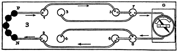
Now, if the ball, D, is carried to the right, a new set of wires, figure 50, are immersed, and those represented in figure 49, as in connection, are taken out of their cups. The fluid now passes from P, of the battery, to the mercury cup, 1; to 5; to 7; to the coils of the multiplier, deflecting the needle to the left; then it passes to cup 8; to 6; to 2; and then to the N pole of the battery; the arrows representing the direction of the current. It will now be found, that the cups, 2 and 3, and 1 and 4 are not in connection, and consequently the current cannot pass along the wires, 3 and 7, and 4 and 8.
Thus, it will appear, that by carrying the ball, D, to the left, the needle is deflected to the right; then, by carrying the ball to the right, the needle is deflected to the left; and that when the ball is brought to the vertical position, the needle is vertical. These three changes enter into the plans of several electric telegraphs, which are to be hereafter described.
Professor Morse’s American Electro Magnetic Telegraph, invented, 1832.
To our readers the principles and arrangement of Morse’s telegraph have been fully explained in the former part of this work. We shall here present some of the evidence of the time of its invention.
Extract from a letter from S. F. B. Morse to the Hon. Levi Woodbury, Secretary of the Treasury, dated Sept. 27th, 1837.
“About five years ago, on my voyage home from Europe, the electrical experiment of Franklin, upon a wire some four miles in length, was casually recalled to my mind, in a conversation with one of the passengers, in which experiment it was ascertained that the electricity travelled through the whole circuit in a time not appreciable, but apparently instantaneous. It immediately occurred to me, that if the presence of electricity could be made visible in any desired part of this circuit, it would not be difficult to construct a system of signs by which intelligence could be instantaneously transmitted. The thought, thus conceived, took strong hold of my mind, in the leisure which the voyage afforded, and I planned a system of signs and an apparatus to carry it into effect. I cast a species of type, which I had devised for this purpose, the first week after my arrival home; and although the rest of the machinery was planned, yet, from the pressure of unavailable duties, I was compelled to postpone my experiments, and was not able to test the whole plan until within a few weeks. The result has realized my most sanguine expectations.”
The following letters were published in the Journal of Commerce, from the originals now in possession of Prof. Morse.
Letter of the Hon. W. C. Rives.
Senate Chamber, September 21st, 1837.
My Dear Sir,—I hope you will find in my multiplied and oppressive engagements here, an apology for not having sooner answered your inquiry on the subject of your Electro Magnetic Telegraph. I retain a distinct recollection of your having explained to me the conception of this ingenious invention, during our voyage from France to the United States in the year 1832, and that it was, more than once, the subject of conversation between us, in which I suggested difficulties which you met and solved with great promptitude and confidence.
I beg leave to assure you, that it would give us all great pleasure to renew, in personal intercourse at home, the agreeable souvenirs of our acquaintance, and friendly relations abroad.
I remain with great respect, Your most obd’t serv’t,
W. C. RIVES.
Prof. S. F. B. Morse.
Letter of Capt. William W. Pell, of the packet ship Sully.
New York, Sept. 27th, 1837.
Dear Sir—On my arrival here I received your letter, calling upon my recollection for what was said on the subject of an electric telegraph, during the passage from Havre, on board of the ship Sully, in October, 1832. I am happy to say, I have a distinct remembrance of your suggesting, as a thought newly occurred to you, the possibility of a telegraphic communication being effected by electric wires. As the passage progressed, and your idea developed itself, it became frequently a subject of conversation. Difficulty after difficulty was suggested as obstacles to its operation, which your ingenuity still labored to remove, until your invention, passing from its first crude state through different grades of improvement, was, in seeming, matured to an available instrument, wanting only patronage to perfect it, and call it into reality; and I sincerely trust that circumstances may not deprive you of the reward due to the invention, which, whatever be its source in Europe, is with you at least, I am convinced, original.
When you observed to me a few days before leaving the ship, “well, Captain, when you hear of the telegraph one of these days, as the wonder of the world, remember the discovery was made on board the good ship Sully,” I, then, little thought, I should ever be called upon to throw into the scale, my mite of testimony in support of your claims to priority of invention, for what seemed so startling a novelty.
With my respects and best wishes, I subscribe myself, WILLIAM W. PELL.
Samuel F. B. Morse, Esq.
A subsequent letter from Captain Pell, dated February 1st, 1838, after having seen the operation of the telegraph at the University, has the following paragraph:
“When, a few days since, I examined your instrument, I recognized in it the principles and mechanical arrangements, which, on board, I had heard you so frequently explain through all their developments.”
From a letter now in possession of the author, and addressed to him by Prof. Morse, we make the following extract:
“In 1826, the lectures, before the New York Atheneum, of Dr. J. F. Dana, who was my particular friend, gave to me the first knowledge ever possessed of electro magnetism; and some of the properties of the electro magnet; a knowledge which I made available in 1832 as the basis of my own plan of an electro telegraph. I claim to be the original suggestor and inventor of the electric magnetic telegraph, on the 19th of October, 1832, on board the packet ship Sully, on my voyage from France to the United States, and, consequently, the inventor of the first, really practicable telegraph on the electric principle. The plan then conceived and drawn out in all its essential characteristics, is the one now in successful operation. All the telegraphs in Europe, which are practicable, are based on a different principle, and, without an exception, were invented subsequently to mine.
“The thought occurred to me, in a general conversation, as seated at the table with the passengers, in which the experiments of Franklin to ascertain the velocity of electricity through three or four miles. The thought at once occurred to me that electricity might be made the means of conveying intelligence, and that a system of signs might easily be devised for the purpose. I ought, perhaps, to say, that the conception of the idea of an electric telegraph, was original with me at that time, and I supposed that I was the first that had ever associated the two words together, nor was it until my invention was completed, and had been successfully operated through ten miles, that I, for the first time, learned, that the idea of an electric telegraph had been conceived by another. To me it was original, and its total dissimilarity from all the inventions and even suggestions of others, may be thus accounted for. I had not the remotest hint from others, till my whole invention was in successful operation. I employed myself in the wakeful hours of the night, as well as in the tedious hours of the day, in devising the signs, adapting them to a single circuit of wire, and in constructing machinery which should record the signs upon paper, for I thought of no plan short of a mode of recording.”
On the second of September, 1837, the author, with several others, witnessed the first exhibition of this electric telegraph, and soon after became a partner with the inventor. Immediate steps were taken for constructing an instrument for the purpose of exhibiting its powers before the members of Congress. This was done at the Speedwell Iron Works, Morristown, N.J. and exhibited in operation with a circuit of two miles. A few days after, it was again exhibited at the University of the City of New York, for several days, to a large number of invited ladies and gentlemen. The circuit at this time was increased to ten miles. Immediately after this exhibition the instruments and ten miles of wire were taken to Washington, and continued in operation for several months, in the room of the Committee on Commerce at the capitol. Its history and progress, after this period, may be gathered from the preceding documents, printed by order of Congress.
Schilling Electric Telegraph.
We make the following extract in relation to Schilling’s telegraph from the Polytechnic Central Journal, Nos. 31, 32, 1838:
“Baron Schilling, of Caunstadt, a Russian Counsellor of State, likewise occupied himself with telegraphs by electricity, (see Allgem Bauztg, 1837, No. 52, p. 440,) and had the merit of having presented a much simpler contrivance, and of removing some of the difficulties of the earlier plans. He reckoned many variations to the right, or left, following in a certain order for a telegraphic sign, as, indeed, in this manner, the needle was strongly varied, and only came to rest gradually, after many repeated vibrations; he introduced a small rod of platinum, with a scoop, which dipped into a vessel of quicksilver, placed beneath the needle, and by the check given, changed the vibration of the needle into sudden jerks. In order to apprise the attendant of a telegraphic despatch, he loosed an alarm. How much of this contrivance was Schilling’s own, or whether a portion of it was not an imitation of Gauss and Weber, the author cannot decide, but that Schilling had already experimented, probably with a more imperfect apparatus, before the Emperor Alexander, and still later before Emperor Nicholas, is affirmed by the documents quoted.”