HISTORY OF TELEGRAPHS, (continued 2)
Reading edition
From the report of the “Academy of Industry,” Paris, February, 1839, we make the following extract, in relation to the same subject:
“At the end of the year, 1832, and in the beginning of 1833, M. Le Baron de Schilling constructed, at St. Petersburg, an electric telegraph, which consisted in a certain number of platinum wires, insulated and united in a cord of silk, which put in action, by the aid of a species of key, 36 magnetic needles, each of which were placed vertically in the centre of a multiplier. M. de Schilling was the first who adapted to this kind of apparatus, an ingenious mechanism, suitable for sounding an alarm, which, when the needle turned at the beginning of the correspondence, was set in play by the fall of a little ball of lead, which the magnetic needle caused to fall. This telegraph of M. de Schilling, was received with approbation by the Emperor, who desired it established on a larger scale, but the death of the inventor postponed the enterprise indefinitely.”
Dr. Steinheil in his article “upon telegraphic communication,” published in the London Annals of Electricity, states, “that the experiments instituted by Schilling, by the deflection of a single needle, seems much better contrived, than the arrangement which Davy has proposed, in which illuminated letters are shown by the removal of screens placed in front of them.”
It would appear, that the French report is either incorrect, or that M. de Schilling had two plans in contemplation. His plan as intimated in the first and third extracts, is that of using a single needle in the form of a galvanometer, by means of which he made his signals, for instance, one deflection to the right might denote e; two i; three b: one deflection to the left t; two s; three v. His code of signals would then be devised in this manner:
rl A rrrl K llr U
rrr B lrrr L lll V
rll C lrl M rlrl W
rrl D lr N lrlr X
r E rlr O rllr Y
rrrr F llrr P rlrr Z
llll G lllr Q rrlr &
rlll H lrr R lrrl go on
rr I ll S lrll stop
rrll J l T llrl finish
rlrlr 1 lrlrl 6
rrlrr 2 rrllr 7
rlllr 3 rllrr 8
lrrrl 4 llrll 9
lrrll 5 llrrl 0
If, however, his plan was that ascribed to him, by the Academy of Industry, of using 36 needles and 72 wires, it was exceedingly complicated and expensive, and was similar to that invented by Mr. Alexander, with the exception that Schilling used twice the number of wires.
[27] The Electro Magnetic Telegraph, of Counsellor Gauss and Professor William Weber, invented at Göttingen, 1833.
The deflection of the magnetic bar, by means of the multiplier, through the agency of the galvanic fluid, excited by the magneto electric machine, is the basis of their plan.
Fig. 51.
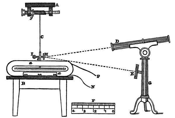
Figure 51 represents a side view of the apparatus, used at the receiving station: a, a is a side view of the multiplier, composed of 30,000 feet of wire, (almost 5½ miles,) upon a table, B: n, s is the magnetic bar, weighing 30 pounds, from which rises a vertical stem, o, upon which is a rod at right angles, supporting a mirror, H, on one end, and at the other a metallic ball, I, as a counteracting weight to that of the mirror. The magnetic bar is suspended by a small wire, fastened to the vertical stem, and at the top is wound round the spiral of the screw, i, which turns in the standards, h′ and h, upon the platform, A, and which is secured to the ceiling. In the standards, h′, there is cut a female screw, of the same gradation as that upon which the wire is wound. By this means, the magnetic bar may be raised or let down, by turning the screw, without taking the bar from its central position in the multiplier: g is a screw for fastening the spiral shaft, when properly adjusted. P and N are the two ends of the wire of the multiplier. G is a stand for supporting the spy-glass, D, and also the case, E, into which slides the scale, F. The mirror, H, is at right angles with the magnetic bar, and presents its face to the spy-glass, D, as also to the scale at E. It is so adjusted, that the reflection of the scale at E, from the mirror, may be distinctly seen by the spy-glass. If the magnetic bar turns either to the right or left, the mirror must move with it, and if a person is observing it through the spy-glass, the scale will appear to move at the same time, thereby presenting to the eye of the observer another part of the scale than that seen when the bar is not deflected. The figures on the scale will show in what direction the bar has turned, and thus render it distinct to the observer, the only apparent object of the mirror, spy-glass and scale.
For the purpose of generating the galvanic fluid, they use the magneto electric machine. Their plan, being unwieldy and difficult to operate, is omitted, and in its stead, we introduce that form of it, invented by Dr. Page, which has already been described in figures 45, 46 and 47. There is also required for the purpose of making the desired deflections of the magnetic bar, a commutator, or pole changer, such as we have described in figures 48, 49 and 50. Figure 51 represents that portion of the apparatus at the receiving station. The magneto electric machine, and the pole changer, properly connected, are the instruments of the transmitting station. Two wires, or one wire and the ground, form the circuit between these two stations. The machine is put in operation by turning the crank, and the person sending the intelligence is stationed at the commutator, and directs the current through the extended wires to the multiplier of the receiving station, so as to deflect the bar to the right or left, in any succession he may choose, or suspend its action for any length of time.
“But in the apparatus for observation, the observer looks into the spy-glass, and writes up the kind and results of the variations of the magnetic needle. In order to have a control of the recorder, let there be a good number of spy-glasses directed towards the same mirror, in which observers may watch independently of each other. Suppose that five variations of the magnetic needle signifies a letter. L denotes a variation to the left, and R to the right. Then, might r r r r r denote A; r r r r l denote B; r r r l r denote C; r r l r r denote D; and so on. In the whole, we obtain, by the different arrangements of the five, which are made with the two letters, R and L, 32 different telegraphic signs, which may answer for letters and numbers, and of which we can select those where the most changes are introduced between r and l, as the most common letters, in order, in the best possible manner, to notice the constant variations of the magnetic needle.”
The following would be the alphabetical signs, as arranged from the above directions:
A rrrrr I or Y llrll R rrrll
B rrrrl K lrrrl S or Z rrlrl
C rrrlr L rlrrr T llrlr
D rrlrr M rrlll U rlllr
E rlrlr N lllll V lrrll
F lrrrr O lrlll W llllr
G or J lrlrr P lrlrl
H rlrrl Q llrrr
Numerals.
1 rllll 6 rllrr
2 rrllr 7 lllrl
3 rlrll 8 llrrl
4 rllrl 9 lrrlr
5 lllrr 0 lrllr
It will be seen, that, by representing the letters and numerals with these variously combined deflections of the needle, words and sentences may be transmitted. At the end of each letter there is a suspension of the action of the bar for a short time, and at the end of a word, a still longer pause. This plan of an electric telegraph was tried for a distance of one mile and a quarter, in Göttingen. Of its further success, we are not informed.
Experiment of Messrs. Taquin & Ettieyhausen.[28]
“Messrs. Taquin and Ettieyhausen made experiments with a telegraphic line over two streets in Vienna, 1836. The wires passed through the air and under the ground of the Botanic garden.”
No other account appears to have been given of their experiments than that quoted above.
Electro Magnetic Printing Telegraph, invented by Alfred Vail, September, 1837.
Soon after my connection with Professor Morse as copartner, and at the time I was constructing an instrument for exhibiting the advantages of his telegraph to a committee of Congress, it occurred to me, that a plan might be devised, by means of which the letters of the alphabet could be employed in recording telegraphic messages. I immediately gave it my attention, and produced the following plan:
Figure 52 represents a front and side view of the instrument.
Figure 55 is a top view.
Figure 56 is a back view.
The same parts are represented by the same letters in the three views. In figure 52, Q, Q is the platform upon which the whole instrument is placed. M and M are wooden blocks supporting parts of the instrument, K is the helix of the soft iron bar, H, passing through its centre, and there is another coil and bar directly behind this; the two making the electro magnet. G is its armature, fastened to the lever, F, F, which has its axis at I, (seen in figure 55, at X, X.) R is a brass standard for supporting the lever, F, upon its axis, by means of two pivot screws: a and a are two screws passing vertically, through the standard, R, for limiting the motion of the lever, F, F. J is a spiral spring, at its upper end, fastened to the lever, F, and at its lower end passes through the screw, L, by which it is adjusted, so as to withdraw the armature from the magnet, after it has ceased to attract, and for other purposes, hereafter to be explained. N and O is a brass frame, containing the type wheel, B′, and the pulley, E and U. P and P represent the edge of a narrow strip of paper, passing between the type wheel and pulley, E. D is the printer, which, at the bottom, forms a joint with the end of the lever F and r. B represents twenty-four metallic pins, or springs, projecting at right angles from the side of the type wheel; each pin corresponding in its distance from the centre of the type wheel, to its respective hole, represented by dots upon, the index, C; so that if the pin is put in any one of the holes, the type wheel, in its revolution, will bring its corresponding pin in contact with it.
Fig. 52.
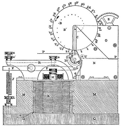
There are 24 holes corresponding to the following letters of the alphabet. A, B, C, D, E, F, G, H, I, K, L, M, N, O, P, Q, R, S, T, U, V, W, X, and the types are lettered accordingly. The cog wheels, T and S, are a part of the train of the clock. The lever, F, F, has two motions, one up and another down, and both are employed by an attachment at the end of the lever, r, and in the following manner: figures 53 and 54 represent a front and end view of the roller, E, and printer, D, (figure 52,) enlarged. D is the printer, figure 53, of the form shown by D, (figure 54.) E is the roller over which the paper, P, is carried. A is the front of the type having ears, h, h, projecting from each side. Through the sides of the printer, D, D, a rod, U, passes, in order to give more firmness to the frame. The rod projects a little on each side of the frame at J, J. These projections slide in a long groove in the frames, N and O, figure 52, by which the printer is kept in its position, and allowed freely to move up and down. It will be observed that the upper parts of the frame, D, D, extends over the top of the roller, E, and nearly touch each other, but are so far separated, as to let the type, A, of the type wheel, in its revolution, freely pass between them: d′, d′, are the sides of the joint, which are connected with the lever, F, fig. 52. From the construction of this part, it will appear that if the printer, D, is brought down by the action of the magnet upon the lever, the two projections, k, k, will come in contact with the ears, h, h, and bring the type in contact with the paper upon the roller, E, and produce an impression. In figure 54 is shown a ratchet wheel, i, on the end of the roller, E, a catch, e, and spring, c′, adapted to the ratchet. Upon the release of the lever, F, fig. 52, the spring, J, will carry down the lever on that side of its axis, and up at r, which will cause the roller, E, to turn, and consequently the paper, P, to advance so much by the action of the catch, e, upon the ratchet wheel, as will be sufficient for printing the next letter.
Fig. 53. Fig. 54.
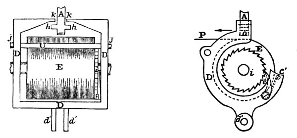
Figure 55 represents a top view of the machine. S is the barrel upon which is wound a cord, sustaining a weight which drives the clock train, and upon the same shaft with it is a cog wheel driving the pinion, m, on the shaft, T; and on the same shaft, T, is another cog wheel, driving the pinion, n, of the type wheel shaft, I′. K and K, are the helices of the large magnet, of which H and H are the soft iron arms. M, M, M, M, are the blocks which support the instrument. F and F is the lever, a and a its adjusting screws; x′ and x′ its axis; k and k are the two upper coils of the two electro magnets at the back part of the instrument for purposes hereafter to be described; x is the wire soldered to the plate buried in the ground; p is the wire proceeding to the battery; c is the connecting wire of the two electro magnets, k and k; w is the support of the pendulum; v is the escapement wheel; A is the type wheel; D and D is the printer, and B the roller over which the paper, P, is carried.
Fig. 55.
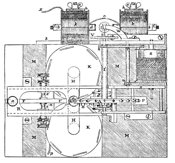
Fig. 56.
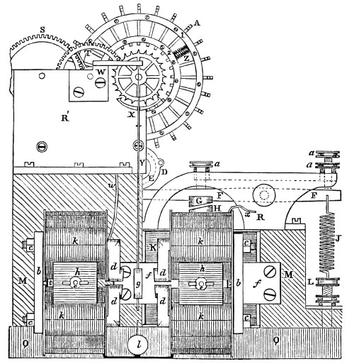
Figure 56 represents a back view of the instrument; k, k and k, k are the coils of two electro magnets, surrounding the soft iron bars, d, d and d, d; b and b are the flat bars through which d, d and d, d pass, and are fastened together by the screw nuts c, c and c, c. The right hand electro magnet is fastened to the blocks, M and M, by the support, f and f; from which proceeds a bolt passing between the coils, k and k, and the block, h, with a thumb-nut upon it, by which the whole is permanently secured. In the same manner the left hand magnet is secured to the block, M. R′ is the outside portion of the brass frame containing the clock work. W is a standard fastened to R′, for supporting the pendulum, Y. X, Y, and l are parts common to a chronometer for measuring the time, viz. the escapement and pendulum. The escapement wheel has 24 teeth, corresponding in number with the type on the wheel, and such is the arrangement of the parts, that when the pendulum is upon the point of return, either on the right or left hand, a type is directly over the paper, and the armature, g, is near the face of one or the other of the magnets; so that, if an impression is to be made with the type, thus brought to the paper, the pendulum, Y, is ready to be held by the magnet at the same time from making another swing until the type has performed its office, which will be hereafter explained.
A shows the type as they are arranged on the wheel. The types are square, and move freely in a groove, cut out of the brass type wheel. At 1 and 2 are seen flat brass rings, which are screwed to the wheel, and over the types, confining them to their proper places. Z is a spiral spring, of which there is one to each type, by means of which the type is brought back to its former position, after it is released by the printer. Through each type there is a pin, against which the inner end of the spiral spring rests. The outer end of the spring rests against the circular plate. W represents the wire from the upper helix, soldered to the metallic frame, R′. The two helices of the left hand magnet are joined together, and from the bottom helix the wire proceeds to the lower coil of the right hand magnet. These two helices are likewise connected, and the wire leaves the upper coil at x. Thus the wire is continuous from w to x. From x, the wire is continued to a copper plate, buried in the earth. The frame, R′, being brass, the arbor of the type wheel, and the wheel itself, and each being in metallic contact, they answer as a continuous conductor with the wire, w, for the galvanic fluid.
The index, c, figure 52, is insulated from the frame, N, being made of ivory. There is inserted in the ivory, a metal plate, containing the holes, to which is soldered a wire, q, connected with the back coil, K. The two helices being connected, the wire of the front helix comes off at p, and from thence is connected with one pole of the battery; from the other pole, it is extended to the distant station, and is there connected with a similar instrument. It will be observed, that the circuit is continuous, except between the type wheel and the metal plate in the ivory. When neither station is at work, the batteries of both are thrown out, and their circuits, retaining in them the magnets of both stations, are closed. For this purpose, there is an instrument at each station, resembling in some respects the pole changer, figures 48, 49 and 50. If one of the stations wish to transmit by reversing his circuit instruments, the battery is instantly brought into the circuit. Through the agency of the clock work and weight, and the pendulum, both instruments are vibrating together, and their type wheels are so adjusted, that when A type, of one station, is vertical, the A type, of the other station, is also vertical. Now, suppose one station wishes to transmit to the other, the word Boston, for example: he first brings his battery in the circuit, then places a metallic pin in the hole of his index, C, marked for the letter B. When the type wheel shall have brought round the pin, corresponding to the type, B, on the wheel, its pin will come in contact with the inserted pin of the index, and instantly the circuit is established. The fluid, passing through the coils of the magnets, on each side of the pendulum, will hold it, and also passing through the coils, K, will bring down the lever, F, F, and with it, the printer, D, which, as heretofore described, in figures 53 and 54, will bring the type, with considerable force, against the paper. The instant the two pins have come in contact with the moving pin, it is taken out and put in the hole, O, when the same operation is performed, and in like manner for the remaining letters of the word. The pin can be so arranged, as to be thrown out the instant a complete contact is made.
The rapidity of this printing process would be as follows: Suppose the pendulum makes two vibrations in a second; that is, it goes from right to left in half a second, and returns in half a second. Since, then, a single letter is brought to the vertical position, ready to be used if needed, at the end of each vibration, it is clear, that two letters are brought to the vertical position every second, or 120, every minute. This is not, however, the actual rate of printing; for, in the word Boston, the type wheel, after B is printed upon the paper, must make so much of a revolution as will bring the letter O to the paper. This will require 12 vibrations of the pendulum; S will require 4; T, 1; O, 18, and N, 22; equal to 57, to which add 6, the time required to print each letter, will make it 63. This, divided by 2, gives 31½ seconds, the time necessary to print 6 letters. If we now take an ordinary sentence, and estimate, in the same manner, the time required to print it at the distant station, we shall be able to find what number of letters it can print per minute.
“There will be a declaration of war in a few days, by this government, against the United States. Orders have just been received to have all the public archives removed to Jalapa, which is sixty miles in the interior, for safe keeping.”
Here are 184 letters, and would require 2266 vibrations, to which add 184, the number of letters would give 2450 half seconds, equal to 1225 seconds, the time required for printing the message; or over 20 minutes; the rate being six and two-thirds seconds for each letter.
If, however, a vocabulary is used, with the words numbered, and instead of using the 26 letters of the alphabet on the type wheel, we substitute the 10 numerals, in their place, we reduce the time required for a revolution of the wheel, and it is clear that this same message may be transmitted in much less time.
The following numbers represent the words of the same message, in the numbered vocabulary: 48687, 54717, 4165, 1, 12185, 34162, 54078, 25393, 1, 18952, 11934, 6177, 48766, 21950, 1106, 48652, 51779, 46532, 34475, 22991, 28536, 4321, 40254, 49085, 22991, 1391, 48652, 39087, 3845, 41278, 49085, 28536, 54536, 28668, 45008, 31634, 25393, 48652, 27326, 19865, 42813, 28592. Here are 42 numbers, and 196 figures. To 196 add 42, the spaces required, and we have 238 impressions to make, to write the sentence thus represented. By calculation, we find there is required, in order to bring each numeral and space in its proper succession, to the vertical position, 1624 vibrations of the pendulum, which, at the rate of two to the second, gives the time required to transmit the message at 812 seconds, or nearly 13 minutes, being at the rate of 18⅓ letters per minute.[29]
If, however, the vibrations of the pendulum are increased at the rate of 4 in a second, then the time required for the transmission of the message would be almost 7 minutes, and at the rate of 36⅔ letters per minute.[30] If it be increased to 6 vibrations per second, then the time would be 4½ minutes, and at the rate of 55 impressions per minute.
The modes of using the English letter for recording telegraphic messages are various, and they may be classed, as, First, Those which are rapid in transmission; expensive in construction, and complicated in machinery. Second, The less rapid in transmission; economical in construction, and simple in its machinery. Third, The slow in transmission; less expensive than the first class in construction; but complicated in its machinery.
To the first class, belong those using 26 types; one for each of the letters of the alphabet, and 13 extended wires, from station to station, with more or less battery. These types are arranged in a row, directly over the paper which receives the impression, and consequently require a strip of paper some 4 or 5 inches broad. Each type is furnished with an electro magnet and lever, answering as a hammer to bring down the types upon the paper. As the types are arranged in a straight line, they would present the following order:
A B C D E F G H I J K L M N O P Q R S T U V W X Y Z
- - - - - - - P R
- - - - I - N - - T
- - - - I - N - - -
- - G - - - - T
- E - - L - -
- E G - - R
A - - P
H
Here we have the style of this kind of printing. By spelling the letters on the first line, then on the second, and so on, the words “Printing Telegraph” can be made out. Those letters which follow each other in the word, and also follow each other in the alphabet, are placed upon the same line, but when a letter occurs preceding the last, a new line must be taken, otherwise the word cannot be read. It will appear, that in this mode, sometimes two or three, or four letters, may be printed at one and the same instant, where they succeed each other in alphabetical order. This plan is extremely rapid for one instrument, but extremely slow for thirteen wires.
Supposing two such instruments are used upon a line of 40 miles, and suppose the wire to cost per mile, fifty dollars. The expense for wire alone would be $26,000. There are other expenses which we will omit in this, as well as those plans which will be described hereafter. Let it be assumed, in order to make equal comparison throughout, that the number of successive motions of the type lever, in these various plans about to be given, are 4 to a second. But as this instrument may make, with two or more of its levers, two or more impressions per minute, let it be 8 instead of 4 per second. It will then be capable of transmitting 480 letters per minute. With all this, there are many disadvantages, which will be developed as we proceed.
Under the same class, there is another plan, using the 26 types upon the ends of as many levers, each lever employing the electro magnet, and the line consisting of 13 wires. In this arrangement the types are made to strike in any succession required by the message, at the same point upon the paper, falling back and resuming their first position, after having printed their letter, in order to allow the next type to occupy the same point previously occupied by the other. The printing of this plan will appear on paper as ordinary printing. Thus, Printing Telegraph. If we suppose that 4 hammers, carrying type, can strike the same point in a second, and each resume their original position in succession, thus passing each other without collision, it may print at the rate of 240 letters per minute.[31] The instrument would be a complicated one and subject to derangement.
To the second class, belong all those which print in letters of an hieroglyphical character. The first plan is that employing one wire and one motion. Under this head, is that of Prof. Morse’s. He employs but one wire and one electro magnet for printing, which has but one motion. Suppose this to be capable of operating with the same speed as the preceding, viz. four motions per second. The telegraphic alphabet as adopted by Prof. Morse require for each letter the following number of motions of the type or pen lever, as lines require time in proportion to their length, they are so estimated: A 3, B 5, C 4, D 4, E 1, F 4, G 5, H 4, I 2, J 6, K 5, L 5, M 4, N 3, O 3, P 5, Q 5, R 4, S 3, T 2, U 4, V 5, W 5, X 5, Y 5, Z 5.
If we take the standard number of types for each letter constituting it printer’s case, considering Z as 2, we shall have A 85, B 16, C 30, D 44, E 120, F 25, G 17, H 64, I 80, J 4, K 8, L 40, M 30, N 80, O 80, P 17, Q 5, R 62, S 80, T 90, U 34, V 12, W 20, X 4, Y 20, Z 2. The whole number of letters are 1177. The number of motions required to transmit them would be 3420, to which add, one motion for the time required to space a single letter, and we have 4597 motions, made in printing 1177 letters which will make the average number of motions to each letter 3¹⁰⁶⁶⁄₁₁₇₇, nearly 4. Let it be 60 per minute. Expense for one wire of 40 miles, $2000.
Second plan, is that where two wires are used, two magnets, two type levers, and the telegraphic characters, such as are represented in table 1, page 30. The first three letters require three motions each; the next 16, require 2 each, and the last 7, require 3 each. Taking the 1177 letters, the motions required to transmit them in the characters of this alphabet, would be, 2195 + 1177 for spaces and would equal 3372, which divided by 1177, would give the average number of motions at 2¹⁰¹⁸⁄₁₁₇₇ for each letter, nearly three or 80 per minute. Cost of wire $4000.
Third plan, is that using three wires, three magnets, three type levers and the telegraphic characters represented in table second, page 30. The seven first would require one motion each, and the remainder two each. Taking 1177 letters, the motions required to transmit them, would be 1917 + 1177 for spaces, and would equal 3094 motions, which, divided by 1177, would give the average number of motions 2⁷⁴⁰⁄₁₁₇₇ for each letter, nearly 2⅔, or 85 letters per minute. Cost of wire $6000.
Fourth plan consists in using four wires, four electro magnets, four type levers, and the telegraphic characters of the third table. The first sixteen letters require the time of but one motion each; the remainder, two each. Using 1177 letters, the motions required to transmit them would be 1506 + 1177 for spaces, and would equal 2683, which divided by 1177, would give the average number of motions 2³²⁹⁄₁₁₇₇ for each letter, nearly 2⅓, or 103 letters per minute. Cost of wire $8000.
Fifth plan, is that of using five wires, five electro magnets, five type levers, and the telegraphic characters of the 4th table. The characters would require one motion each, equal to 1177 + 1177 for spaces, and would equal 2354, which, divided by 1177, would give the average number of motions, 2 for each letter, or 120 letters per minute. Cost of wire $10,000.
We now come to the third class, in which 26 types are used, arranged upon the periphery of a wheel, in alphabetical order, and require to be brought to one certain point, where the paper is ready to receive the impression of the type, by another arrangement, distinct from the type wheel and its machinery. Of this plan, is that which has been already described in figures 52, 55 and 56. The estimate is there carried out, at 4 motions per second, gives 36⅔ letters per minute. Cost of wire $2000.
The following table will show the comparative value of these various methods:
Letters per minute. Cost. Number of wires. On Morse’s plan. No.
1st Class. 1st plan, 480 $26,000 13 780 1

2d “ 240 26,000 13 780 2
2d Class. 1st plan, 60 2,000 1 60 3
2d “ 80 4,000 2 120 4
3d “ 85 6,000 3 180 5
4th “ 103 8,000 4 240 6
5th “ 120 10,000 5 300 7
3d Class. 1st plan, 37 2,000 1 60 8
We find by comparison that Morse’s plan, No. 3, of using a single wire, with a single instrument, produces 60 characters per minute; while No. 1, with 13 wires, and one instrument, produces 480 characters per minute. Let, however, the 13 wires be multiplied by 60, (the number of characters which a single instrument of the plan, No. 3, can transmit,) the number of characters which 13 wires, with 13 instruments would then produce, are 780 or 300 more than the single instrument, with 13 wires. The same comparisons may be made with the other plans, and it will be found that no advantage can be gained by their adoption.
All electro magnetic telegraphs require as their basis, the adoption of the electro magnet, where recording the intelligence is an object, and it would seem, must be applied in a manner equivalent to that mode adopted by Prof. Morse; that is, the application of the armature to a lever, and its single movement produced by closing and breaking the circuit. It is, therefore, safe to assume, that whatever improvement in one plan may be made to increase the rapidity of the movements of those parts of the telegraph which belong to the electro magnet, are equally applicable to any other plan, provided too much complication, already existing, does not counteract and defeat the improvement.
Some plans, however, use an extra agent besides the electro magnet, which is employed for measuring the time of the revolution of the type wheel, and the electro magnet is only called in, occasionally, to make the impression. In such plans the rapidity of communication demands the combined action, alternately, of both magnets. This, of course, increases the complication, and must certainly be considered a departure from other more simple arrangements. Whatever will reduce the inertia of mechanical movements and bring them to act with an approximate velocity, at least of the fluid itself, will increase the rapidity of transmission. The more the instrument is encumbered with the sluggish movements of material bodies, the less rapid, inevitably, must be its operation, even where several co-operating agents are assisting, in their respective spheres, to increase the rapidity of the motion. Such is the case with the several kinds of letter printing telegraphs: very weighty bodies, comparatively speaking, are set in motion, stopped, again set in motion, and along with this irregular motion, other parts perform their functions. There must be a courtesy observed among themselves, or matters do not move on as harmoniously as could be desired. This is not always the case, especially where time is the great question at issue.
All printing telegraphs which use type, arranged upon the periphery of a wheel, must have, of necessity, these several movements, viz. the irregular revolution of the type wheel, stopping and starting at every division or letter; the movement of the machinery, called the printer; the irregular movement of the paper, at intervals, to accommodate itself to the letter to be printed; the movement of the inking apparatus, or what is not an improvement in cleanliness, paper of the character used by the manifold letter writer. So many moving parts, are so many impeding causes to increased rapidity, and are, to all intents and purposes, a complication.
The requirements of a perfect instrument are: economy of construction, simplicity of arrangement, and mechanical movements, and rapidity of transmission. To use one wire is to reduce it to the lowest, possible economy. If there is but one movement, and that has all the advantages which accuracy of construction, simplicity of arrangement and lightness, can bestow upon it, we might justly infer that it appeared reduced to its simplest form.
The instrument employed by Professor Morse has but a single movement, and that motion of a vibratory character; is light and susceptible of the most delicate structure, by which rapidity is insured; the paper is continuous in its movement, and requires no aid from the magnet to carry it.
The only object that can be obtained by using the English letters, instead of the telegraphic letters, is, that the one is in common use, the other is not. The one is as easily read as the other, the advantage then is fanciful and is only to be indulged in at the expense of time, and complication of machinery, increasing the expense, and producing their inevitable accompaniments, liability of derangement, care of attendance, and loss of time.
Wheatstone’s Electric Needle Telegraph, invented in 1837.
The following description is taken from a pamphlet, published by T. S. Hodson, 15 Cross street, Hallon Garden, London, 1839, for the proprietors. It is unnecessary to copy the legal and technical wordy mass of the specification, embracing fifty-nine pages of closely printed matter of octavo size. A full description will be given, with the accompanying figures, so as to enable the reader fully to comprehend Mr. Wheatstone’s plan.
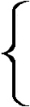
His arrangement requires the service of five galvanometers, in every respect similarly constructed as that described by the figures 27, 28 and 29. Figure 57 is a representation of his dial, which is also a covering to the case containing, in the interior, the five galvanometers and their wires, (shown at the opening in the dial board,) and numbered, 1, 1; 2, 2; 3, 3; 4, 4, and 5, 5. The coils of the multipliers are secured with their needles to the case, having each exterior needle projecting beyond the dial, so as to be exposed to view. Of the wires from the coils, five are represented as passing out of the side of the case, on the left hand, and are numbered 1, 2, 3, 4 and 5. The other five wires pass out on the right hand, and are numbered in the same manner. The wires of the same number as the galvanometer, are those which belong to it, and are continuous. Thus the wire 1, on the left hand, proceeds to the first coil of galvanometer 1, then to the second coil, and then coming off, passes out of the case, and is numbered 1, on the right hand. So of the other wires, thus numbered. The dial has permanently marked upon it, at proper distances and angles, twenty of the letters of the alphabet, viz. A, B, D, E, F, G, H, I, K, L, M, N, O, P, R, S, T, V, W, Y. On the margin of the lower half of the dial are marked the numerals, 1, 2, 3, 4, 5, 6, 7, 8, 9 and 0. The letters C, J, Q, U, X, Z, are not represented on the dial, unless some six of those already there are made to sustain two characters each, of which the specification is silent. Each needle has two motions; one to the right, and the other to the left. For the designation of any of the letters, the deflection of two needles are required, but for the numerals, one needle only. The letter intended to be noted by the observer, is designated, in the operation of the telegraph, by the joint deflection of two needles, pointing by their convergence to the letter. For example, the needles, 1 and 4, cut each other, by the lines of their joint deflection, at the letter V, on the dial, which is the letter intended to be observed at the receiving station. In the same manner any other letter upon the dial may be selected for observation. Suppose the first needle to be vertical, as the needles 2, 3 and 5, then needle 4 being only deflected, points to the numeral 4, as the number designed.
Fig. 57.
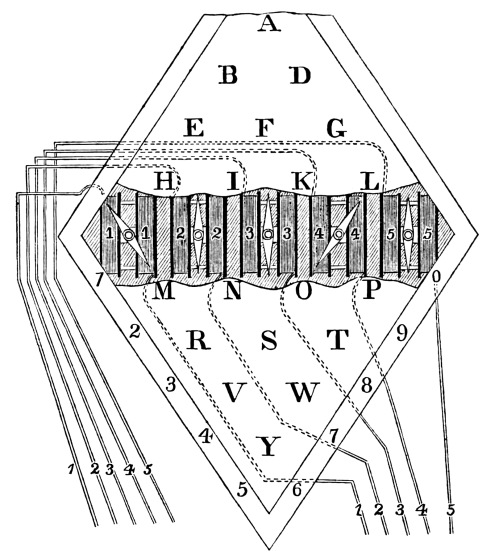
We will now proceed to describe the arrangement of the springs and buttons upon the platform, C, C, figure 58, (representing a top view,) by the operation of which, any two needles may be deflected to designate a letter, or one needle to designate a numeral.
Fig. 58.
The numbers 6, 1, 2, 3, 4 and 5, represent keys of thin brass, and elastic, and are each fastened to a wooden support, D, D, by means of two screws. These keys are continued under and project beyond, the brass bar, L and L, which is supported by two standards, R and R. Whenever these keys are not pressed upon, they are each in metallic contact with the bar, R and R. The numbers 7, 8, 9, 10, &c. represent ivory buttons with a metallic stem beneath them, passing through a hole in the spring, or key, and on the lower side of the spring the stem is enlarged, so as to form a kind of hammer, designed to make a metallic contact with the two brass bars, beneath the springs, and represented as supported by the standards, N and N and P and P. Each of the buttons have a small wire spiral spring, to which they are fastened, and the small spring is itself fastened to the larger spring. O represents the galvanic battery, with its poles in connection with the two metallic bars, N and P.
Figure 59 represents a side view of the key arrangement. F is the platform. E the wooden support of the six keys. H is the larger spring, or key, secured to the support by screws, h. The spring is observed to project beyond the metallic cross bar, L, after passing beneath it. R is the support of the cross bar, L. N and O are two of the ivory buttons, upon their spiral springs, a and c. Below the button, O, is a shoulder, formed at i, upon the stem which passes through the spring, H, and another shoulder is formed by the hammer, u, below the spring. It will be observed, that two buttons of the same key are never used at the same time. If the button, O, is to be pressed down, the weaker spring, c, will permit it to descend until the upper shoulder comes in contact with the larger spring, H, when more pressure is applied, and that spring is brought down, breaking its contact with the metallic cross bar, L, until the hammer, u, comes in contact with the metallic plate, n, upon the support, K, and as the plate, n, is connected with N pole of the battery, the connection is formed with it. It will, however, be noticed, that the button, N, not being pressed upon, will not, (though it descends with the larger spring,) be brought in contact with the other plate upon the support, J, and connected with the positive pole of the battery. To the end of each spring, a wire, S, is soldered, the purpose of which will be shown hereafter.
Fig. 59.
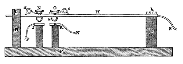
Fig. 60.
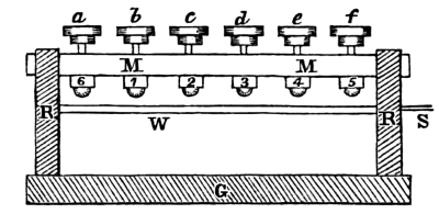
Figure 60 represents an end view of the key arrangement; a, b, c, d, e, f, are the buttons, M and M the metallic cross bar, beneath which are seen the ends of the six larger springs, 6, 1, 2, 3, 4 and 5. R and R are the supports of the bar, M and M. G is the platform. W is the support of the metallic plates, with which the hammers of the little keys, or buttons, come in contact. S the wire leading to the battery.
Having shown the several parts of Mr. Wheatstone’s plan, we will proceed to describe the arrangement of two termini, as prepared for transmitting intelligence. Figure 61 represents the arrangement of one station, which we may suppose to be Paddington. Figure 62 represents the plan of the other station, which we will suppose to be Slough. The distance between these two places is eighteen miles.
In figure 61, it will be seen, that a wire is soldered to the end of each of the springs 6, 1, 2, 3, 4 and 5, and are respectively connected with the five wires of the dial, and the common communicating wire, number 6, which does not pass through the dial, nor is connected with any of the galvanometers. On the right hand side of the dial, the wires are extended until they are shown as broken. From this point to the opposite one, figure 62, where the wires appear also as interrupted, we may suppose 18 miles to intervene. The wires here proceed to the dial of the Slough station, making their proper connections with their respective galvanometers, and from thence are continued and soldered to their springs of the key arrangement, with the exception of wire, number 6, which passes direct to the key, 6, without going through the dial case. In both figures, is represented the battery, O, consisting of six cups. The wire from one pole of the battery is connected with the N metallic plate, the other wire with the P metallic plate. While none of the buttons are pressed down, the battery is not in action, and it will also be observed that the circuits are all complete. The action of the keys, then, is this, by a single operation to break the circuit formed with the cross bar, L, L, and, at the same time, bring into the circuit, the battery, O.
The following numbers, representing the buttons, are those necessary to be pressed down, in order to signal the letters and numerals on the dial:
Letters.
For A, buttons 10 and 17. For M, buttons 9 and 12.
“ B, “ 10 “ 15. “ N, “ 11 “ 14.
“ D, “ 12 “ 17. “ O, “ 13 “ 16.
“ E, “ 10 “ 13. “ P, “ 15 “ 18.
“ F, “ 12 “ 15. “ R, “ 9 “ 14.
“ G, “ 14 “ 17. “ S, “ 11 “ 16.
“ H, “ 10 “ 11. “ T, “ 13 “ 18.
“ I, “ 12 “ 13. “ V, “ 9 “ 16.
“ K, “ 14 “ 15. “ W, “ 11 “ 18.
“ L, “ 16 “ 17. “ Y, “ 9 “ 18.
Numerals.
For 1, buttons 7 and 10. For 6, buttons 8 and 9.
“ 2, “ 7 “ 12. “ 7, “ 8 “ 11.
“ 3, “ 7 “ 14. “ 8, “ 8 “ 13.
“ 4, “ 7 “ 16. “ 9, “ 8 “ 15.
“ 5, “ 7 “ 18. “ 0, “ 8 “ 17.
Fig. 61. PADDINGTON.
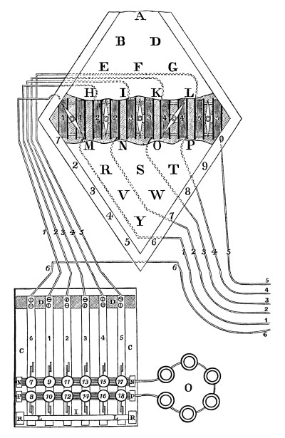
Fig. 62. SLOUGH.
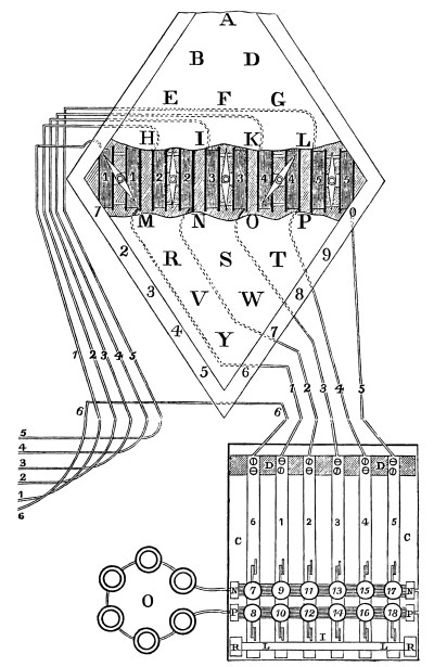
The direction of the current, when the letter V is to be signalled, is this: pressing down the buttons, 9 and 16, at the Paddington station, the fluid leaves the battery, O, along the wire to the cross bar, P; then to the hammer of the button, 16; then to the spring, 4; then along wire, 4, to the galvanometer, 4, and through it, deflecting the lower half of the needle to the left; then along the extended wire, 4, to the dial, and galvanometer, 4, of the Slough station, deflecting the lower half of that needle to the left; then to wire, 4, leaving the dial, to key, 4; then to the cross bar, L and L; and along the cross bar to key, 1; then to wire, 1; then to galvanometer, 1; and through it, deflecting the lower half of the needle to the right; thence it proceeds along the extended wire, 1, to the Paddington station; entering the dial to the galvanometer, 1, deflecting the lower half of the needle to the right; then along wire, 1, to the key, 1; then to button, 9; then to the cross bar, N, beneath; and then to the negative pole of the battery, O. It will be observed, that the needles of both stations, thus deflected, point to the same letter, V. In Mr. Wheatstone’s arrangement, but one person can transmit at the same time, although he uses six extended wires. One must wait while the other is transmitting.
If a numeral is to be signalled, it is obvious, that but one galvanometer is needed. We will, therefore, suppose that the needle, 1, is vertical.
Let the buttons, 7 and 16, be pressed down, at the Paddington station. The current then leaves the positive pole of the battery, O, to the cross bar, P; then to the key, 4; then along wire, 4, to galvanometer, 4, deflecting the lower half of the needle to the left; from thence to the Slough station to galvanometer, 4, deflecting the lower half of the needle to the left; then to wire, 4; then to key, 4; then to the cross bar, L and L, and along it to key, 6; then to wire, 6, and along the extended wire to the Paddington station, to key, 6; then to the cross bar beneath the button, 7; then to the negative pole of the battery, O. The needles, 4 and 4, of both stations, are simultaneously deflected, so as to point to the figure, 4, on the margin of the dial.
In this manner the circuits required for each letter and numeral may be traced out. Now, suppose the message to be sent from the Paddington station to the Slough station, is this, “We have met the enemy and they are ours.” The operator at Paddington presses down the buttons, 11 and 18, for signalizing upon the dial of the Slough station, the letter W. The operator there, who is supposed to be constantly on the watch, observes the two needles pointing at W. He writes it down, or calls it out aloud, to another, who records it, taking, according to a calculation given in a recent account, two seconds at least for each signal. Then the buttons, 10 and 13, are pressed down, and the needles are observed to point at E; and so for the remaining letters of the sentence, U excepted, which has no letter on the dial.
The peculiarity of Mr. Wheatstone’s plan, is, the employment of six wires for one independent line of communication. The use of five galvanometers, with their needles, by the deflection of which, 30 letters and numerals are pointed out. The messages are not recorded by the instrument itself, but it is necessary that a person be constantly observing the successive movements of the needles, and note them down as they point to the signal. This plan was invented in 1837, and as Prof. Wheatstone took out letters-patent in the United States, in 1840, for this arrangement, it is a fair inference, that at that time, this was his simplest and most perfect method.
Steinheil’s Electric Telegraph.
Description of the magneto electrical telegraph, erected between Munich and Bogenhausen, in 1837, by Dr. Steinheil,[32] Professor of Mathematics and Natural Philosophy at the University of Munich, taken from the Annals of Electricity, Magnetism and Chemistry, conducted by William Sturgeon, London, April, 1839.
Fig. 63.
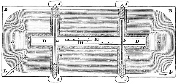
A, A represents a vertical section, through the centre of the coil of copper wire. C is the interior brass frame, round which the wire is wound. B and B are the sides of the frame; I, I, I, I are four brass tubes, soldered to the interior brass frame, and passing through the centre of the coil to its exterior, with a screw cut in the end of each; D and D are two permanent magnets movable on their axis, a and b. These spindles, a and b, on each side of the magnets, pass up the hollow of the tubes, and having their ends pointed, enter the centre cavity of the four thumb screws, J, J, J, J, by which they are supported, and delicately adjusted, so as to move easily and freely. L and L are the ends of the wire leaving the coil. H and K are two ink holders, attached to the magnets, which will be explained hereafter.
Fig. 64.
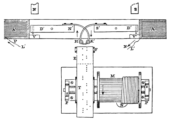
Figure 64 represents a horizontal section of the coil, and magnets D′ and D′, as above described, together with the other arrangements of the instrument for receiving intelligence. The magnetic bars are so situated in the frame of the multiplier, that the north pole, N′, of the one, is presented to the south pole, S′, of the other. To the ends which are thus presented to each other, but which, owing to the influence they mutually exert, cannot well be brought nearer, there are screwed on two slight brass arms, supporting little cups, H′ and K′. These little cups, which are meant to be filled with printing ink, are provided with extremely fine perforated beaks, that are rounded off in front. When printing ink is put into them, it insinuates itself into the tube of their beaks, owing to capillary attraction; and without running out, forms at their apertures, a projection of a semiglobular shape. These little cups are seen at H′ and K′, and in figure 63 at H and K. The horizontal section shows, also, the position of the magnets in the instrument, with the beaks of the pens near the continuous band, or ribbon of paper, E, which is brought in front of the pens vertically from below, over a small roller, F. The paper is supplied from a large roll on a wooden cylinder, upon which is a cog wheel, and connected with a train of wheels and a vane, to regulate the rate of supply. The paper is drawn along before the pen by being wound upon a cylinder, T, concealed by the paper, and on the same shaft with the barrel, M, upon which is wound a cord supporting a weight, N, below. The shaft is supported in the standards, o and o, which are fastened to a plate of brass, P and P, also secured to the platform of the instrument. The barrel revolves in the direction of the arrow upon it.
When the electricity is transmitted through the coil of the indicator, both magnetic bars, D′ and D′, make an effort to turn in a similar direction upon their vertical axis, a and b. One of the cups of ink, therefore, advances towards the paper, while the other recedes. To limit this action, two plates, V and V′, are fastened at the opposite ends of the free space, allowed for the play of the bars, and against which the other ends of the bars press. Only the end of one bar can, therefore, start out from within the multiplier at a time, the other being retained in its place. In order to bring the magnetic bars back to their original position, as soon as the deflection is completed, recourse is had to two small movable magnets, a portion of which is seen at N and S, whose distance and position are to be varied till they produce the desired effect. This position must be determined by experiment, inasmuch as it depends upon the intensity of the current called into play.
Having described the instrument, its operation is as follows: At the transmitting station is the pole changer, such as we have described in figures 48, 49 and 50, and the magneto electric machine such as is described in figures 45, 46, and 47, and are properly connected, and in the circuit with the instrument of the receiving station, such as we have just described. For one single circuit, one wire extends from the transmitting to the receiving station, the return half of the circuit is the earth. Thus the current passes from the generator along the extended wire to the receiving station, and to the copper plate, then returns through the ground to the copper plate of the transmitting station, to the pole changer and the magneto electric machine. Thus the circuit is complete.
It is clear, from what has preceded, that when the pole changer is thrown to the left side, (the machine being in operation,) the fluid is made to pass in the direction of the arrows, shown at P and N. Then the N′ pole of the left hand magnet advances with its pen, K′, to the paper, E, and a dot is made, and the S′ pole of the right hand magnet recedes with its pen, H, from the paper, until the other end of the magnet strikes the stop, V′. Now, if the letter to be formed, requires two dots in succession from the same pen, the circuit is broken, and the fixed magnets, N and S, bring back the deflecting magnets, D′ and D′, to their former position, when the pole changer is again thrown to the left, and the magnets are deflected in the same manner as at first. Thus two dots are marked upon the paper, on the right hand line. But, now, let the pole changer be thrown to the right hand side, and the current is reversed. The N′ pole of the left hand magnet, with its pen, K, recedes from the paper until it strikes the stop, V, and the S pole of the right hand magnet, with its pen, H′, advances to the paper and makes its dot upon it on the left hand line. The pole changer is then instantly brought to the middle position, and the magnets resume their natural place, by the assistance of the stationary magnets, N and S. The sign which has been marked upon the paper during this operation is · · ·, and represents 9.
The following represents Mr. Steinheil’s telegraphic alphabet:
· ·· · ·· ·· ···· · · · · ·
· · · · · · · ···· · · ·· ··
A B D E F G H CH SCH I K L
··· ·· · · ·· · · · · · ··
··· ·· ·· ·· · · · · ··
M N O P R S T V W Z
··· · ·· ·· · ··· · · · · ··
· · · · ··· · ·· ·· · ··· · ···
1 2 3 4 5 6 7 8 9 0
Masson’s Electric Telegraph.
“In 1837, M. Masson, Professor of Philosophy at Caen, made trial of an electric telegraph, at the college of that city, for a distance of about 600 metres. He employed, for developing the galvanic current, an electro magnetic apparatus, similar, on the contrary, to that of Mr. Pixii, and made it act on magnetic needles placed at two ends of the circuit. Since that time, however, M. Masson has endeavoured to simplify and gradually improve his apparatus.”[33]
Davy’s Needle and Lamp Telegraph.
The following extracts from the London Mechanic’s Magazine, vol. 28, page 296 and 327, 1837, is all the description we are able to find in relation to it:
“There is a case, which may serve as a desk to use in writing down the intelligence conveyed; and in this, there is an aperture about sixteen inches long, and three or four wide, facing the eyes, perfectly dark. On this the signals appear as luminous letters, or combinations of letters, with a neatness and rapidity almost magical. The field of view is so confined, that the signals can be easily caught and copied down without the necessity even of turning the head. Attention, in the first instance, is called by three strokes on a little bell; the termination of each word is indicated by a single stroke. There is not the slightest difficulty in decyphering what is intended to be communicated.”
Extract from page 327.
“In front of the oblong trough, or box, described by your correspondent, a lamp is placed, and that side of the box next the lamp is of ground glass, through which the light is transmitted for the purpose of illuminating the letters. The oblong box is open at the top, but a plate of glass is interposed between the letters and the spectator, through which the latter reads off the letters as they are successively exposed to his view. At the opposite side of the room, a small key board is placed, (similar to that of a piano forte, but smaller,) furnished with twelve keys; eight of these have each three letters of the alphabet on their upper surfaces, marked A, B, C; D, E, F; and so on. By depressing these keys in various ways, the signals or letters are produced at the opposite desk, as previously described, how this is affected is not described by the inventor, as he intimated that the construction of certain parts of the apparatus must remain secret. By the side of the key board, there is placed a small galvanic battery, from which proceeds the wire, 25 yards in length, passing round the room. Along this wire the shock is passed, and operates upon that part of the apparatus which discloses the letters or signals. The shock is distributed as follows: The underside of the signal keys are each furnished with a small projecting piece of wire, which, on depressing the keys, is made to enter a small vessel, filled with mercury, placed under the outer ends of the row of keys; a shock is instantly communicated along the wire, and a letter, or signal, is as instantly disclosed in the oblong box. By attentively looking at the effect produced, it appeared as if a dark slide were withdrawn, thereby disclosing the illuminated letter. A slight vibration of the (apparent) slide, occasionally obscuring the letter, indicated a great delicacy of action in this part of the contrivance, and although not distinctly pointed out by the inventor, is to be accounted for in the following manner: when the two ends of the wire of the galvanic apparatus are brought together, over a compass needle, the position of the needle is immediately turned, at right angles, to its former position; and again, if the needle is placed with the north point southward, and the ends of the wire again brought over it, the needle is again forced round to a position at right angles to its original one. Thus, it would appear, that the slide or cover over the letters, is poised similarly to the common needle, and that by the depression of the keys, a shock is given in such a way as to cause a motion from right to left, and vice versa, disclosing those letters, immediately, under the needle so operated upon.”
Alexander’s Electric Telegraph, from the (Scotsmen) Mechanic’s Magazine, Nov. 1837.
“A model to illustrate the nature and powers of this machine was exhibited on Wednesday evening at the Society of Arts in Edinburgh. The model consists of a wooden chest, about five feet long, three feet wide, three feet deep at the one end, and one foot at the other. The width and depth in this model are those which would probably be found suitable in a working machine, but it will be understood that the length in the machine may be a hundred or a thousand miles, and is limited to five feet in the model, merely for convenience. Thirty copper wires extend from end to end of the chest, and are kept apart from each other. At one end (which, for distinction’s sake, we shall call the south end) they are fastened to a horizontal line of wooden keys, precisely similar to those of a piano forte; at the other, or north end, they terminate close to thirty small apertures, equally distributed in six rows of five each, over a screen of three feet square, which forms the end of the chest. Under these apertures on the outside, are painted, in black paint, upon a white ground, the twenty-six letters of the alphabet, with the necessary points, the colon, semicolon, and full point, and an asterisk, to denote the termination of a word. The letters occupy spaces about an inch square. The wooden keys, at the other end, have also the letters of the alphabet, painted on them in the usual order. The wires serve merely for communication, and we shall now describe the apparatus by which they work.
This consists, at the south end, of a pair of plates, zinc and copper, forming a galvanic trough, placed under the keys; and at the north end, of thirty steel magnets, about four inches long, placed close behind the letters painted on the screen. The magnets move horizontally on axes, and are poised within a flat ring of copper wire, formed of the ends of the communicating wires. On their north ends they carry small square bits of black paper, which project in front of the screen, and serve as opercula, or covers, to conceal the letters. When any wire is put in communication with the trough at the south end, the galvanic influence is instantly transmitted to the north end; and in accordance with the well known law, discovered by Oersted, the magnet at the end of that wire instantly turns round to the right or left, bearing with it the operculum of black paper, and unveiling a letter. When the key, A, for instance, is pressed down with the finger at the south end, the wire attached to it is immediately put in communication with the trough; and at the same instant, letter A, at the north end is unveiled, by the magnet turning to the right, and withdrawing the operculum. When the finger is removed from the key, it springs back to its place; the communication with the trough ceases; the magnet resumes its position, and the letter is again covered. Thus by pressing down with the finger, in succession, the keys corresponding to any word or name, we have the letters forming that word, or name, exhibited at the other end; the name Victoria, for instance, which was the maiden effort of the telegraph on Wednesday evening.”
Fig. 65.
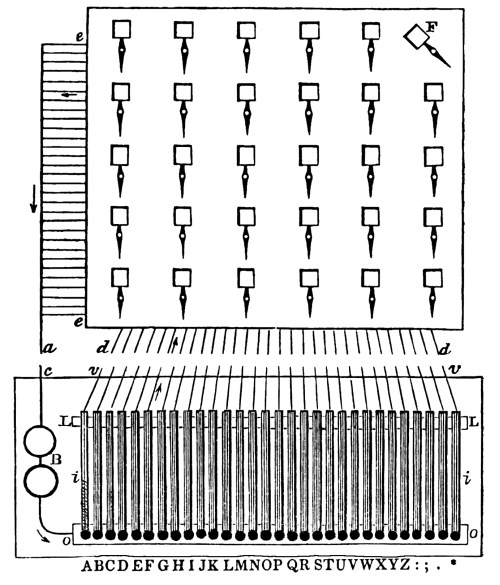
The above description is all that we have been able to obtain in relation to this plan of an electric telegraph and here introduce, figure 65, to illustrate it. The 30 needles are represented on the screen, each carrying a shade, which conceals the letter when the needle is vertical. The needle belonging to the letter F, is, however, deflected, and the letter is exposed. The screen is supposed to be at the receiving station. To the left hand of the screen, 30 wires, e, e, are seen joined to one, a; the other 30 wires, d, d, are seen below the screen. These wires may be supposed to extend many miles, and to be joined with their corresponding wires, c, and also v, v, of the transmitting station, where it will be observed, the wire, c, connects with the battery at one pole, and from the other pole a wire is continued and soldered to the metallic plate, o, o, which extend under all the 30 keys, i, i. These keys are each insulated, at their extremity, by being fastened to a wooden standard, L, L, to which a wire is soldered. Now, suppose the key, F, is pressed down, (the sixth key from the left,) the fluid then passes from the battery, B, through the wire to o, the plate; then to the key in contact with it; then to its wire, marked by the arrow; thence through the extended wire to its corresponding wire at the receiving station, denoted by the arrow; then through the coils of the multiplier, deflecting the needle, F; then returns through its wire, at the left, to the common wire, a; then through the extended wire to C, and the battery, of the transmitting station. In this manner any letter upon the screen may be indicated.
Extract from the Report of the Academy of Industry, in reference to a suggestion of M. Amyot of an Electric Telegraph.
“M. Amyot announced, in a letter addressed to the Academy of Sciences, in April, 1838, that he also proposed to construct an electric telegraph. It was to consist of a single current, which would move a single needle, which needle would of itself write on paper, with mathematical precision, the correspondence which might be transmitted to the other extremity, by a simple wheel on which it should be written by means of points, differently spaced, the same as they are on the barrels of portable organs. In order to send any news then, he required to write, by means of movable characters, which must be constructed in a certain manner, and immediately it would be repeated and transcribed at the place where he wished to address it, on paper, which could be put into the hands of persons specially employed to transmit despatches. But all that method of execution, which it seems ought to move is clock work, not having been sufficiently described by the author, the most vague uncertainty yet reigns as to the true construction of that apparatus, which appears to us to have been for M. Amyot, rather the occasion, than the end, of this communication; for indeed he attempted to make the possibility admitted of establishing a universal telegraphic language of his invention.”
Edward Davy’s Electric Telegraph.[34]
The following description of Mr. Davy’s telegraph is taken from his specification and drawings, published in the Repertory of Patent Inventions. Although the specification has given the basis of his plan, yet the description contained therein, and the drawings representing his plan, are so obscure and deficient, that to have given it to the public in that form, would have represented it as perfectly impracticable. He has failed to state the number of signals which it is capable of giving. He has committed great errors in the arrangement of his wires for producing signals. He has introduced two keys, which produce the same signals as two others in the same arrangement. He has employed three extended wires for communicating from one station to another station, and by his arrangement of them, could not have obtained more than four signals. He has also very obscurely described his escapement, by which his marking cylinder is made to advance one division at a time for receiving the signals. This latter difficulty, however, we have been enabled to clear up, by a description of it in a work published by Mr. Bain. Notwithstanding the imperfections and obscurities of his specification and drawings, we have endeavoured to carry out his plan, and give it a practical shape, perhaps, as Mr. Davy originally designed it.
As it is now described, there are 26 signals, or marks, indicating letters. The employment of four wires instead of three, or if Mr. Davy chooses to use for the common communicating wire the ground, which is perfectly practicable, it will reduce the number to three, the number he has specified. We have introduced one key more, and so arranged the two superfluous keys as to make them available. With this preliminary, we will proceed with the description.
Fig. 66.
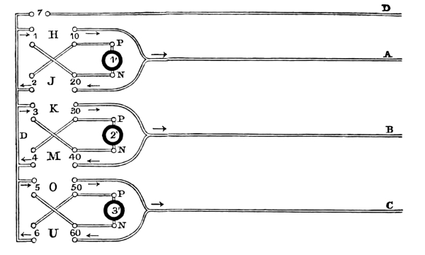
Fig. 67.
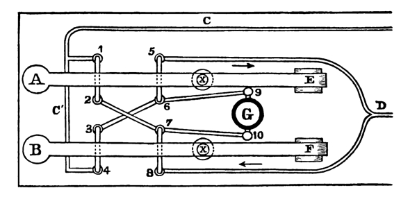
Figure 66 represents a top view of the arrangement of the wires, mercury cups, and batteries of the transmitting station. The close parallel lines represent the wires, of which D, A, B and C are those which proceed to the receiving station. 1′, 2′ and 3′ are the three batteries, of which, P and N are their respective poles. The small circles formed at the termination of the wires, and marked 7, 1, 10, 2, 20, &c. are mercury cups, in which the terminating wires are immersed. The wires 1 and 20, and 2 and 10, &c. which cross each other, are not in contact, but perfectly insulated. The wires shown in this figure, are all secured permanently, with their mercury cups, to one common base board. The letters H, J, K, M, O and U represent the places of the six finger keys, used in transmitting signals. There is, also, another key at 7, for uniting the wire, D and D. In this figure, however, the keys themselves are omitted, in order to render more clear the arrangement of wires under and around them. Another figure, 67, is here introduced to illustrate the plan of one set of wires and their two keys. In figure 67 is represented, in a top view, the two wooden keys, A and B, and their axes, at E and F. G is the battery, of which, 9 is the positive pole, and 10 the negative pole. The small circles, marked 1, 2, 3, 4, 5, 6, 7 and 8 represent the mercury cups. C and C′, and also, D, are the extended wires. The keys, A and B, have each two wires, passing at right angles through the wooden lever. The wires of the key, A, are marked 1 and 2, and 5 and 6, and those of the key, B, are marked 3 and 4, and 7 and 8. These wires, directly over the mercury cups, are bent down a convenient length, so as to become immersed in the cups, when the lever is depressed, and rise out of them, when the lever is elevated. Now, if the key, A, is depressed, the cup, 1, is brought in connection with cup 2; and 5 is connected with 6, by the wires, supported by the lever, being immersed in the mercury; and the key, B, not being depressed, there is no connection of the cup 3 with 4; or 7 with 8. At X and X, under the lever, are springs, which keep the lever elevated; and, consequently, the wires out of the cups, when the keys are not pressed down.
Fig. 68.
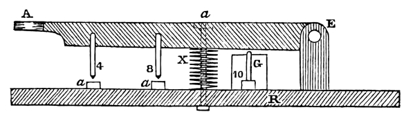
Figure 68 represents a side view of the lever, or key, A, and its axis at E. R is the platform supporting the standard of the axis; the stationary wires; the battery, G; and the mercury cups, a, a and 10. X is the spiral spring, for the purpose of carrying back the lever, after the finger is taken off and sustaining it in its elevated position. Through the centre of the spiral, passes a rod, with a head upon it at the top of the lever, to limit its upward motion. At its lower end, the rod is secured in the platform, R. 4 and 8 are the two wires supported by the lever, A, and are seen to project down directly over the mercury cups, a and a, so that by depressing the key, they both enter the cups and form a metallic connection. The key, B, figure 67, has the same fixtures and is similarly arranged as the key, A, represented above.
Fig. 69.
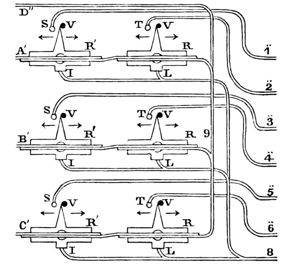
Figure 69 represents a top view of die arrangement of multipliers at the receiving station. R′, R′ and R′; R, R, and R are six magnetic needles, or bars, each of which move freely upon a vertical axis passing through their centres. The lower point of their axes is immersed in cups of mercury, in which also terminate the wires, I, I, I and L, L, L. The wires, D″, A′, B′ and C′, are those coming from the transmitting station. A′, B′ and C′, each enter the needle arrangement, and first passing from left to right, over the magnetic bars, R′, R′ and R′, in the direction of their length, then down and under and round, making many turns, leave these three needles and pass under the needles, R, R and R, and in like manner from right to left round them, making a number of turns, then pass off and unite together, in the wire, 9, which is a continuation of D″. This wire is called the common communicating wire,[35] and the wires, A′, B′ and C′ are called signal wires. At right angles, there projects from each magnetic bar, a metallic tapered arm, which rests against the studs, V, V, V, V, V, V, when the needle is undisturbed. But when the needles are made to move in the direction, to carry the arms to the left, they are brought in contact with the metallic stops, S, S, S and T, T, T. To each of these stops, it will be observed, a wire is soldered, and continued respectively from S, S, S to ̈1, ̈3, ̈5, and from T, T, T to ̈2, ̈4, ̈6. It will also be observed, that from each of the mercury cups below the magnetic bars, the wires, I and L, and I and L, and I and L, proceed and unite in pairs at, L, L, L; these three united wires are then continued, and the whole are joined in one at 8. The wires, ̈1, ̈2, ̈3, ̈4, ̈5, ̈6, are continued, in a manner hereafter to be described, and are connected with one pole of a battery. The wire, 8, is also continued and connected with the other pole. So that if any one of the needles should be made to move its arm to the left, thereby coming in contact with its metallic stop, the circuit would be complete and the current would pass along the wire, ̈1, for example, to the metallic stop, then to the arm, and to the magnetic bar; then to the axis; then to the mercury; then to the wire, I, and thence to the wire, 8. In the same manner the current would pass if any other arm was brought against its metallic stop. All the wires represented in this figure are permanently secured in their places upon a common platform.
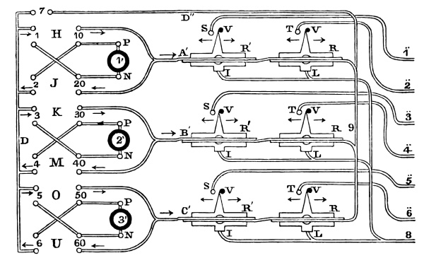
In order to understand the combined operation of the keys and needles, figure 70 is here introduced. The right hand figure, is the same as figure 69, and the left hand the same as figure 66.
Fig. 70. TransmittingPart of Receiving
Station.Station.
The wires, D″, A′, B′ and C′, are detached from their corresponding wires of the transmitting station, and it may be imagined that many miles of wire intervene and connect the two. In the left hand figure, those mercury cups above and below, 1 and 10, are joined by two wires passing through a moving lever, in the same manner as has been described in figure 67. We will, therefore, call the key, carrying these two connecting wires, H. In like manner the key for the cups above and below the numbers, 2 and 20, is called J; for 3 and 30, is K; for 4 and 40, is M; for 5 and 50 is O; for 6 and 60, is U. The key which connects the two mercury cups on the right and left of number 7, of the wire, D″, is called 7. There are 7 keys; two for each battery, 1′, 2′ and 3′, and each wire, A′, B′ and C′; and one for the common wire, D″.
It will now appear, that if the key, U and 7, are depressed, the cups above and below, numbers 6 and 60; and the cups on each side of number 7, will be connected together so that the current leaving, P, or the positive pole of the battery, 3′, goes to the lower cup, 50; then by the stationary cross wire to upper cup, 6; then passes to lower cup, 6, by the wire supported by the lever, U, which is now pressed down, and its ends immersed in the two cups; then along the wire, D, to the left hand cup, 7; then to the right hand cup, 7, by the wire supported by the lever, 7, and which is immersed in the two cups; then through the extended wire to D″, of the receiving station; then through 9, to the two multiplying coils of the wire, C′, deflecting the arm of the needle, R, to the right, against the stop, V; and the arm of the needle, R′, to the left against the metallic stop, S, as indicated by the arrow at S; then along the extended wire, back to the lower cup, 60, of the transmitting station; then to upper cup, 60, through the wire supported by the lever, U; then to N, the negative pole of the battery, 3′.
It will be observed of the two needles, R and R′, in the circuit of the same wire, C′, that if R is deflected to the right against the stop, V, then R′ will be deflected to the left against the metallic stop, S. The current, to produce these deflections, being through the wire C′, in the contrary direction to that indicated by the arrow of the wire, C′. But if R is deflected to the left against the metallic stop, T, then R′ will be deflected to the right against the stop, V. The current to produce these deflections, will then be through the wire, C′, in the direction of the arrow of that wire. The same effect is produced upon the two other pairs of needles of the wires, A′ and also B′. These contrary movements of the two needles, when a current is passing, are produced by the coils being so wound, (see figure 69,) that the wire passes round one needle in a contrary direction to what it does round the other.
If, now, we depress the keys, O and 7, the cups above and below, 5 and 50, and on each side of number 7, will be connected. The fluid will then pass from P or positive pole of the battery, 3′, to the lower cup, 50; then through the key wire to upper cup, 50; then along the extended wire, C′ to the receiving station; then through the coils of the multipliers, deflecting the arm of the needle, R, to the left against the metallic stop, T; and the arm of the needle, R′, to the right against the stop, V, as indicated by the arrow at V; then to wire, 9 and D″; then along the extended wire back to the transmitting station, to the right hand cup, 7; then by the key wire to the left hand cup, 7; then to wire, D; then to upper cup, 5; and through the key wire to lower cup, 5; then by the cross wire to upper cup, 60, and then to N, or negative pole of the battery.
We have now shown the route of the current, when the keys, U and 7; and the keys, O and 7, were depressed. It will be observed, that when the keys, U and 7 were used, the current through the wire, D″, was from left to right; and when the keys, O and 7, were used, the current was from right to left. Thus, by means of the six keys, the current of each battery may be made to pass in either direction through the common communicating wire, D″. By the keys, U, M, J, with 7, the current is made to pass from left to right along the wire, D″. By the keys, O, K, H, with 7, the current is made to pass from right to left along the wire, D″. By these six keys, all those various deflections of the six needles are produced, which are necessary to close the circuit of such of the wires, ̈1, ̈2, ̈3, ̈4, ̈5, ̈6, with the wire, 8, as are required for marking the signals desired, on an instrument now to be described.
Fig. 71.
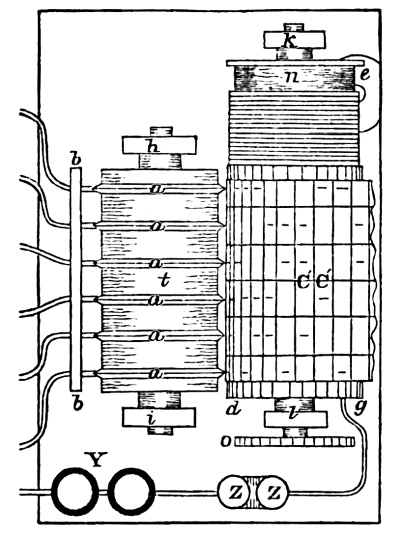
Fig. 72.
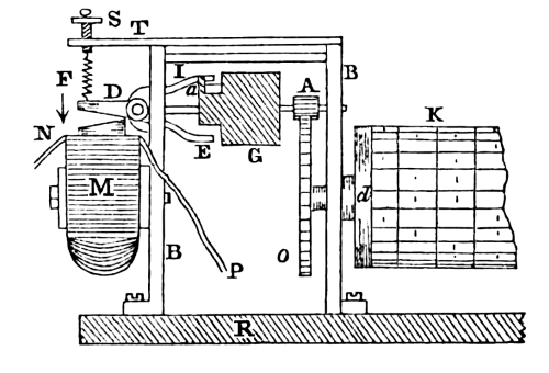
Figure 71 represents a top view of that part of the instrument at the receiving station, by which the signals are recorded. The seven wires on the left of the figure are a continuation of those wires, marked ̈1, ̈2, ̈3, ̈4, ̈5, ̈6, and 8, in figure 70. The first six pass through a wooden support, b and b, and terminate upon the edge of the platinum rings, a, a, a, a, a and a, forming a metallic contact. The six platinum rings surround a wooden insulating cylinder, t, which revolves upon axes in the standards, h and i. The rings are broad where they come in contact with the wooden roller, and are bevelled to an edge where they come in contact with the six wires. Y represents a compound battery, with one pole of which, wire 8, from the needle arrangement, figure 70, is connected, and from the other pole the wire proceeds to the electro magnet, Z, Z; it then passes on and is brought in connection with the metallic cylinder, d, at the point, g. The cylinder, d, revolves upon axes, and is supported in the standards, k and l. To the cylinder is attached a barrel, n, upon which is wound a cord, supporting the weight, e, by which the cylinder is made to revolve. C′, C′, represents a prepared fabric, such as calico, (impregnated with hydriodate of potass and muriate of lime,) and is placed between the platinum rings, a, a, a, a, a, a, and the metallic cylinder, d; o is a cog wheel upon the end of the axis of the cylinder, d, and is connected with other machinery, omitted here, but shown in figure 72, which is a side elevation of part of figure 71: o is the cog wheel, (figure 72,) on the arbor of the cylinder, d. B and B, are the two sides of the frame containing the clock work, and is secured to the platform, R: d is a part only of the metallic cylinder, upon which is seen a portion of the prepared fabric, K. The cog wheel, o, drives the pinion, A, on the shaft of the fly vane, G. M is an end view of the electro magnet, (represented by Z, Z, in figure 71,) of which N and P are the two ends of the wire composing the helix. D is its armature, constructed so as to move upon an axis represented by two small circles. To the armature are connected, and capable of moving with it, two arms, E and I, which project, so as to come in contact with the pallet, a, of the fly, G. F is a spiral spring, one end of which is fastened to the armature, D, and the other passes through a vertical hole in the screw, S, in the bar, T, by which the armature is held up in the position now seen, when not attracted by the electro magnet. Now, if the wires, N and P, connected with battery, Y, (figure 71,) have their circuit closed, the current passing through the helix of the magnet, M, brings down the armature, D, in the direction of the arrow, which raises the arm, I, against which the pallet, a, of the fly vane, is resting, and releases the fly. It then makes a half revolution and is again arrested by the pallet against the lower arm, E, and the cylinder, d, with its fabric, has advanced a half division. If the circuit is now broken, the armature, D, is carried up by the spring, F, at the same time the arm, E, releases the pallet, a, and the fly makes another half revolution, and is again stopped by the arm, I. The cylinder has now made another advance of half a division, which, together, makes a whole division the fabric has advanced. The purposes for which this is designed will now be described.
Fig. 73.
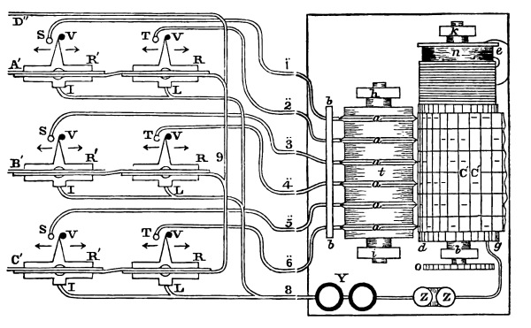
Figure 73 represents a top view of the whole apparatus of the receiving station. The fabric, C′, C′, is marked in equal divisions across it, and in six equal divisions, in the directions of its length, thus marking it into squares. Each platinum ring, a, a, a, &c. (when the instrument is not in operation,) is in contact with the fabric at the middle of the squares across the fabric. It will be observed, that the wires ̈1, ̈2, ̈3, ̈4, ̈5, ̈6 are in connection with the battery, Y, and the circuit complete, except at the arms of the needles. Suppose, for example, the arm of the needle, R′, of the wire, C′, is brought up against the stop of the wire, ̈5, at S; the circuit is then closed, and the current leaves the battery, and passes to the electro magnet, (causing the cylinder and fabric to move half a division,) then to the metallic cylinder, d; then through the fabric, c′, c′, resting upon the cylinder, (where it is in contact with the platinum ring, a, of the wire, ̈5,) then to the platinum ring; then to wire ̈5; then to the metallic stop, S; then to the arm of the needle, R′, along its axis to the mercury; then to the wire, I; then to wire, 8, and to the other pole of the battery, Y. Thus a current is passed through the prepared fabric, and a mark produced thereon, in the middle of its square. If the circuit is now broken, the cylinder moves another half division, which will bring the rings to the centre of the squares, ready for the next signal.
But one battery, Y, is used for all the six circuits, formed with the wire, 8; so that, when three of the circuits are closed at the same instant, as will be shown hereafter, the current passes through the three wires of their respective circuits, making each their appropriate mark upon the fabric.
We now proceed to describe the manner of operating with the two instruments, at their respective stations: and, first, we must here designate each needle by its own peculiar mark of reference. Let the two needles upon the wire, A′, be denoted by, A, S and A, T; those of the wire, B′, by B, S and B, T; and those of the wire, C′, by C, S and C, T. It will appear obvious, from the foregoing description, that but one needle of each wire, A′, B′, C′, can be made to close its circuit at the same instant. However, two needles, or three needles of different wires, may close their circuits at the same instant, but no higher number than three. The various combinations of one mark, two marks, and three marks, upon the same row of six cross divisions of the fabric, constitute the characters representing letters.
Fig. 74.
London.—Transmitting Station.
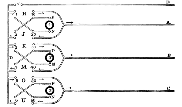
Figure 74 represents the transmitting station, which may be supposed to be London, and figure 75, the receiving station, which may be at Birmingham, with four wires extending from station to station, or three only, if the ground be substituted for the wire, D, D″. The wires, D, A, B and C, are supposed to be united with D″, A′, B′ and C′, respectively. Now, if we depress the keys, in the following order, we shall, for each key, have the following deflections of the two needles, belonging to each key.
No.1.
The keys, H, 7, moves the arm, A, S, to the right, A, T, to the left.
“ J, 7, “ A, S, “ left, A, T, “ right.
“ K, 7, “ B, S, “ right, B, T, “ left.
“ M, 7, “ B, S, “ left, B, T, “ right.
“ O, 7, “ C, S, “ right, C, T, “ left.
“ U, 7, “ C, S, “ left, C, T, “ right.
These are all the various deflections which it is possible to give the six needles. Those, however, which deflect to the right, not closing the circuit, produce no effect, and are of no account. We will, therefore, omit them, and simply give the table, thus:
No.2.
The keys, H, 7, move the arm A, T, to the left. No. 1.
“ J, 7, “ A, S, “ “ 2.
“ K, 7, “ B, T, “ “ 3.
“ M, 7, “ B, S, “ “ 4.
“ O, 7, “ C, T, “ “ 5.
“ U, 7, “ C, S, “ “ 6.
Fig. 75.
Birmingham.—Receiving Station.
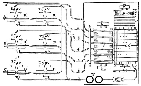
In the following table, the first column represents the keys, which when depressed, produce a deflection of the needles, (represented in the columns, second, third and fourth,) by means of their batteries, and thus closing the circuit of the wires, ̈1, ̈2, ̈3, ̈4, ̈5 and ̈6, by which the fluid, is made to pass through the prepared fabric, and mark upon its space, or spaces, numbered 1, 2, 3, 4, 5 and 6, in the fifth column. In the sixth column are the letters which the marks upon the fabric are intended to represent.
Keys. Needles. Needles. Needles. Spaces on Fabric. Letters.
H, 7, A, T, - - 1, A.
J, 7, A, S, - - 2, B.
K, 7, B, T, - - 3, C.
M, 7, B, S, - - 4, D.
O, 7, C, T, - - 5, E.
U, 7, C, S, - - 6, F.
H, K, 7, A, T, B, T, - 1, 3, G.
J, M, 7, A, S, B, S, - 2, 4, H.
K, O, 7, B, T, C, T, - 3, 5, I.
M, U, 7, B, S, C, S, - 4, 6, J.
H, O, 7, A, T, C, T, - 1, 5, K.
J, U, 7, A, S, C, S, - 2, 6, L.
H, M, A, T, B, S, - 1, 4, M.
J, K, A, S, B, T, - 2, 3, N.
K, U, B, T, C, S, - 3, 6, O.
M, O, B, S, C, T, - 4, 5, P.
H,U, A, T, C, S, - 1, 6, Q.
J, O, A, S, C, T, - 2, 5, R.
H, K, O, 7, A, T, B, T, C, T, 1, 3, 5, S.
J, M, U, 7, A, S, B, S, C, S, 2, 4, 6, T.
H, K, U, A, T, B, T, C, S, 1, 3, 6, U.
J, M, O, A, S, B, S, C, T, 2, 4, 5, V.
H, M, U, A, T, B, S, C, S, 1, 4, 6, W.
J, K, U, A, S, B, T, C, S, 2, 3, 6, X.
H, M, O, A, T, B, S, C, T, 1, 4, 5, Y.
J, K, O, A, S, B, T, C, T, 2, 3, 5, Z.
Telegraphic Letters.
1 · · · · · · · · ·
2 · · · · · · · · ·
3 · · · · · · · · ·
4 · · · · · · · · ·
5 · · · · · · · ·
6 · · · · · · · · · ·
A B C D E F G H I J K L M N O P Q R S T U V W X Y Z
The above represents the telegraphic characters marked upon the prepared fabric. The spaces are numbered from the top.
The first six of the telegraphic letters require each a signal wire, and the common wire, D, with one battery.
The next six require each two signal wires, with two batteries, whose joint currents pass in the same direction on the common wire, D.
The next six require each two signal wires only, with two batteries, joined together so as to form a compound battery. The negative pole of one, connected with the positive pole of the other.
The next two require each three signal wires, with three batteries, whose joint currents pass in the same direction along the common wire, D.
The next six require each, three signal wires only, with three batteries. One of the signal wires with its battery is used as a common wire for the other two. Hence the current of the two batteries of the two signal wires unite in one, and are connected with the battery of the common wire as a compound battery.