FLOW OF STEAM THROUGH PIPES AND ORIFICES
Reading edition
Various formulae for the flow of steam through pipes have been advanced, all having their basis upon Bernoulli’s theorem of the flow of water through circular pipes with the proper modifications made for the variation in constants between steam and water. The loss of energy due to friction in a pipe is given by Unwin (based upon Weisbach) as
E f = f 2 v ² W L ––––––––––––––––– g d ( 37 )
where E is the energy loss in foot pounds due to the friction of W units of weight of steam passing with a velocity of v feet per second through a pipe d feet in diameter and L feet long; g represents the acceleration due to gravity (32.2) and f the coefficient of friction.
Numerous values have been given for this coefficient of friction, f , which, from experiment, apparently varies with both the diameter of pipe and the velocity of the passing steam. There is no authentic data on the rate of this variation with velocity and, as in all experiments, the effect of change of velocity has seemed less than the unavoidable errors of observation, the coefficient is assumed to vary only with the size of the pipe.
Unwin established a relation for this coefficient for steam at a velocity of 100 feet per second,
f = K ( 1 + 3 ––––––– 10 d ) ( 38 )
where K is a constant experimentally determined, and d the internal diameter of the pipe in feet.
If h represents the loss of head in feet, then
E f = W h = f 2 v ² W L ––––––––––––––––– g d ( 39 )
and h = f 2 v ² L –––––––––––– g d ( 40 )
If D represents the density of the steam or weight per cubic foot, and p the loss of pressure due to friction in pounds per square inch, then
p = h D –––––– 144 ( 41 )
and from equations ( 38 ), ( 40 ) and ( 41 ),
p = D v ² L ––––––––––– 72 g d × K ( 1 + 3 ––––––– 10 d ) ( 42 )
To convert the velocity term and to reduce to units ordinarily used, let d 1 the diameter of pipe in inches = 12 d , and w = the flow in pounds per minute; then
w = 60 v × π –– 4 ( d 1 –––– 12 ) ² D
and v = 9.6 w ––––––––––– π d 1 ² D
[Pg 318]
Substituting this value and that of d in formula ( 42 )
p = 0.04839 K ( 1 + 3.6 ––––– d 1 ) w ² L –––––––– D d 1 5 ( 43 )
Some of the experimental determinations for the value of K are:
K = .005 for water (Unwin).
K = .005 for air (Arson).
K = .0028 for air (St. Gothard tunnel experiments).
K = .0026 for steam (Carpenter at Oriskany).
K = .0027 for steam (G. H. Babcock).
The value .0027 is apparently the most nearly correct, and substituting in formula ( 43 ) gives,
p = 0.000131 ( 1 + 3.6 ––––– d 1 ) w ² L –––––––– D d 1 5 ( 44 )
w = 87 ( p D d 1 5 –––––––––––––––––––––––––– ( 1 + 3.6 ––––– d 1 ) L ) ½ ( 45 )
Where w = the weight of steam passing in pounds per minute,
p = the difference in pressure between the two ends of the pipe in pounds per square inch,
D = density of steam or weight per cubic foot, [80]
d 1 = internal diameter of pipe in inches,
L = length of pipe in feet.
TABLE 66 FLOW OF STEAM THROUGH PIPES Initial Gauge Pressure Pounds per Square Inch Diameter [81] of Pipe in Inches, Length of Pipe = 240 Diameters ¾ 1 1½ 2 2½ 3 4 5 6 8 10 12 15 18 Weight of Steam per Minute, in Pounds, With One Pound Loss of Pressure 1 1.16 2.07 5.7 10.27 15.45 25.38 46.85 77.3 115.9 211.4 341.1 502.4 804 1177 10 1.44 2.57 7.1 12.72 19.15 31.45 58.05 95.8 143.6 262.0 422.7 622.5 996 1458 20 1.70 3.02 8.3 14.94 22.49 36.94 68.20 112.6 168.7 307.8 496.5 731.3 1170 1713 30 1.91 3.40 9.4 16.84 25.35 41.63 76.84 126.9 190.1 346.8 559.5 824.1 1318 1930 40 2.10 3.74 10.3 18.51 27.87 45.77 84.49 139.5 209.0 381.3 615.3 906.0 1450 2122 50 2.27 4.04 11.2 20.01 30.13 49.48 91.34 150.8 226.0 412.2 665.0 979.5 1567 2294 60 2.43 4.32 11.9 21.38 32.19 52.87 97.60 161.1 241.5 440.5 710.6 1046.7 1675 2451 70 2.57 4.58 12.6 22.65 34.10 56.00 103.37 170.7 255.8 466.5 752.7 1108.5 1774 2596 80 2.71 4.82 13.3 23.82 35.87 58.91 108.74 179.5 269.0 490.7 791.7 1166.1 1866 2731 90 2.83 5.04 13.9 24.92 37.52 61.62 113.74 187.8 281.4 513.3 828.1 1219.8 1951 2856 100 2.95 5.25 14.5 25.96 39.07 64.18 118.47 195.6 293.1 534.6 862.6 1270.1 2032 2975 120 3.16 5.63 15.5 27.85 41.93 68.87 127.12 209.9 314.5 573.7 925.6 1363.3 2181 3193 150 3.45 6.14 17.0 30.37 45.72 75.09 138.61 228.8 343.0 625.5 1009.2 1486.5 2378 3481
This formula is the most generally accepted for the flow of steam in pipes. Table 66 is calculated from this formula and gives the amount of steam passing per [Pg 319] minute that will flow through straight smooth pipes having a length of 240 diameters from various initial pressures with one pound difference between the initial and final pressures.
To apply this table for other lengths of pipe and pressure losses other than those assumed, let L = the length and d the diameter of the pipe, both in inches; l , the loss in pounds; Q, the weight under the conditions assumed in the table , and Q 1 , the weight for the changed conditions.
For any length of pipe, if the weight of steam passing is the same as given in the table , the loss will be,
l = L ––––––––– 240 d ( 46 )
If the pipe length is the same as assumed in the table but the loss is different, the quantity of steam passing per minute will be,
Q 1 = Q l ½ ( 47 )
For any assumed pipe length and loss of pressure, the weight will be,
Q 1 = Q ( 240 d l ––––––––––– L ) ½ ( 48 )
TABLE 67 FLOW OF STEAM THROUGH PIPES LENGTH OF PIPE 1000 FEET Discharge in Pounds per Minute corresponding to Drop in Pressure on Right for Pipe Diameters in Inches in Top Line Drop in Pressure in Pounds per Square Inch corresponding to Discharge on Left: Densities and corresponding Absolute Pressures per Square Inch in First Two Lines Diameter [82] —Discharge Density—Pressure—Drop 12 10 8 6 4 3 2½ 2 1½ 1 .208 .230 .284 .328 .401 .443 .506 .548 Inches Inches Inches Inches Inches Inches Inches Inches Inches Inch 90 100 125 150 180 200 230 250 2328 1443 799 371 123. 55.9 28.8 18.1 6.81 2.52 18.10 16.4 13.3 11.1 9.39 8.50 7.44 6.87 2165 1341 742 344 114.6 51.9 27.6 16.8 6.52 2.34 15.60 14.1 11.4 9.60 8.09 7.33 6.41 5.92 1996 1237 685 318 106.0 47.9 26.4 15.5 6.24 2.16 13.3 12.0 9.74 8.18 6.90 6.24 5.47 5.05 1830 1134 628 292 97.0 43.9 25.2 14.2 5.95 1.98 11.1 10.0 8.13 6.83 5.76 5.21 4.56 4.21 1663 1031 571 265 88.2 39.9 24.0 12.9 5.67 1.80 9.25 8.36 6.78 5.69 4.80 4.34 3.80 3.51 1580 979 542 252 83.8 37.9 22.8 12.3 5.29 1.71 8.33 7.53 6.10 5.13 4.32 3.91 3.42 3.16 1497 928 514 239 79.4 35.9 21.6 11.6 5.00 1.62 7.48 6.76 5.48 4.60 3.88 3.51 3.07 2.84 1414 876 485 226 75.0 33.9 20.4 10.9 4.72 1.53 6.67 6.03 4.88 4.10 3.46 3.13 2.74 2.53 1331 825 457 212 70.6 31.9 19.2 10.3 4.43 1.44 5.91 5.35 4.33 3.64 3.07 2.78 2.43 2.24 1248 873 428 199 66.2 23.9 18.0 9.68 4.15 1.35 5.19 4.69 3.80 3.19 2.69 2.44 2.13 1.97 1164 722 400 186 61.7 27.9 16.8 9.03 3.86 1.26 4.52 4.09 3.31 2.78 2.34 2.12 1.86 1.72 1081 670 371 172 57.3 25.9 15.6 8.38 3.68 1.17 3.90 3.53 2.86 2.40 2.02 1.83 1.60 1.48 998 619 343 159 52.9 23.9 14.4 7.74 3.40 1.08 3.32 3.00 2.43 2.04 1.72 1.56 1.36 1.26 915 567 314 146 48.5 21.9 13.2 7.10 3.11 0.99 2.79 2.52 2.04 1.72 1.45 1.31 1.15 1.06 832 516 286 132 44.1 20.0 12.0 6.45 2.83 0.90 2.31 2.09 1.69 1.42 1.20 1.08 .949 .877 748 464 257 119 39.7 18.0 10.8 5.81 2.55 0.81 1.87 1.69 1.37 1.15 .97 .878 .769 .710 665 412 228 106 35.3 16.0 9.6 5.16 2.26 0.72 1.47 1.33 1.08 .905 .762 .690 .604 .558 582 361 200 92.8 30.9 14.0 8.4 4.52 1.98 0.63 1.13 1.02 .828 .695 .586 .531 .456 .429
To get the pressure drop for lengths other than 1000 feet, multiply by lengths in feet ÷ 1000.
[Pg 320]
Example: Find the weight of steam at 100 pounds initial gauge pressure, which will pass through a 6-inch pipe 720 feet long with a pressure drop of 4 pounds. Under the conditions assumed in the table , 293.1 pounds would flow per minute; hence, Q = 293.1, and
Q 1 = 293.1 ( 240 × 6 × 4 ––––––––––––––––––– 720 × 12 ) ½ = 239.9 pounds
Table 67 may be frequently found to be of service in problems involving the flow of steam. This table was calculated by Mr. E. C. Sickles for a pipe 1000 feet long from formula ( 45 ), except that from the use of a value of the constant K = .0026 instead of .0027, the constant in the formula becomes 87.45 instead of 87.
In using this table , the pressures and densities to be considered, as given at the top of the right-hand portion, are the mean of the initial and final pressures and densities. Its use is as follows: Assume an allowable drop of pressure through a given length of pipe. From the value as found in the right-hand column under the column of mean pressure, as determined by the initial and final pressures, pass to the left-hand portion of the table along the same line until the quantity is found corresponding to the flow required. The size of the pipe at the head of this column is that which will carry the required amount of steam with the assumed pressure drop.
The table may be used conversely to determine the pressure drop through a pipe of a given diameter delivering a specified amount of steam by passing from the known figure in the left to the column on the right headed by the pressure which is the mean of the initial and final pressures corresponding to the drop found and the actual initial pressure present.
TABLE 68 FLOW OF STEAM INTO THE ATMOSPHERE Absolute Initial Pressure per Square Inch Pounds Velocity of Outflow at Constant Density Feet per Second Actual Velocity of Outflow Expanded Feet per Second Discharge per Square Inch of Orifice per Minute Pounds Horse Power per Square Inch of Orifice if Horse Power = 30 Pounds per Hour 25.37 863 1401 22.81 45.6 30. 867 1408 26.84 53.7 40. 874 1419 35.18 70.4 50. 880 1429 44.06 88.1 60. 885 1437 52.59 105.2 70. 889 1444 61.07 122.1 75. 891 1447 65.30 130.6 90. 895 1454 77.94 155.9 100. 898 1459 86.34 172.7 115. 902 1466 98.76 197.5 135. 906 1472 115.61 231.2 155. 910 1478 132.21 264.4 165. 912 1481 140.46 280.9 215. 919 1493 181.58 363.2
For a given flow of steam and diameter of pipe, the drop in pressure is proportional to the length and if discharge quantities for other lengths of pipe than 1000 feet are required, they may be found by proportion.
Elbows, globe valves and a square-ended entrance to pipes all offer resistance to the passage of steam. It is customary to measure the resistance offered by such construction in terms of the diameter of the pipe. Many formulae have been advanced for computing the length of pipe in diameters equivalent to such fittings or valves which offer resistance. These formulae, however vary widely and for ordinary purposes it will be sufficiently accurate to allow for resistance at the entrance of a pipe a length equal to 60 times the [Pg 321] diameter; for a right angle elbow, a length equal to 40 diameters, and for a globe valve a length equal to 60 diameters.
The flow of steam of a higher toward a lower pressure increases as the difference in pressure increases to a point where the external pressure becomes 58 per cent of the absolute initial pressure. Below this point the flow is neither increased nor decreased by a reduction of the external pressure, even to the extent of a perfect vacuum. The lowest pressure for which this statement holds when steam is discharged into the atmosphere is 25.37 pounds. For any pressure below this figure, the atmospheric pressure, 14.7 pounds, is greater than 58 per cent of the initial pressure. Table 68 , by D. K. Clark, gives the velocity of outflow at constant density, the actual velocity of outflow expanded (the atmospheric pressure being taken as 14.7 pounds absolute, and the ratio of expansion in the nozzle being 1.624), and the corresponding discharge per square inch of orifice per minute.
Napier deduced an approximate formula for the outflow of steam into the atmosphere which checks closely with the figures just given. This formula is:
W = p a –––––– 70 ( 49 )
Where W = the pounds of steam flowing per second,
p = the absolute pressure in pounds per square inch,
and a = the area of the orifice in square inches.
In some experiments made by Professor C. H. Peabody, in the flow of steam through pipes from ¼ inch to 1½ inches long and ¼ inch in diameter, with rounded entrances, the greatest difference from Napier’s formula was 3.2 per cent excess of the experimental over the calculated results.
For steam flowing through an orifice from a higher to a lower pressure where the lower pressure is greater than 58 per cent of the higher, the flow per minute may be calculated from the formula:
W = 1.9 A K √ ( (P - d ) d ) ( 50 )
Where W = the weight of steam discharged in pounds per minute,
A = area of orifice in square inches,
P = the absolute initial pressure in pounds per square inch,
d = the difference in pressure between the two sides in pounds per square inch,
K = [Pg 322] a constant = .93 for a short pipe, and .63 for a hole in a thin plate or a safety valve.
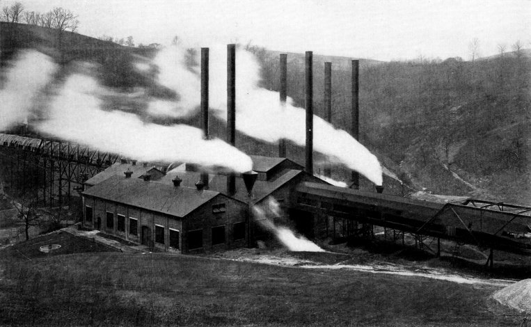
Vesta Coal Co., California, Pa., Operating at this Plant 3160 Horse Power of Babcock & Wilcox Boilers
FOOTNOTES
[Pg 323]